
A Brief Description of High Temperature Solid Oxide Fuel Cell’s Operation, Materials, Design, Fabrication Technologies and Performance

 ,
, 
Abstract
:1. Introduction
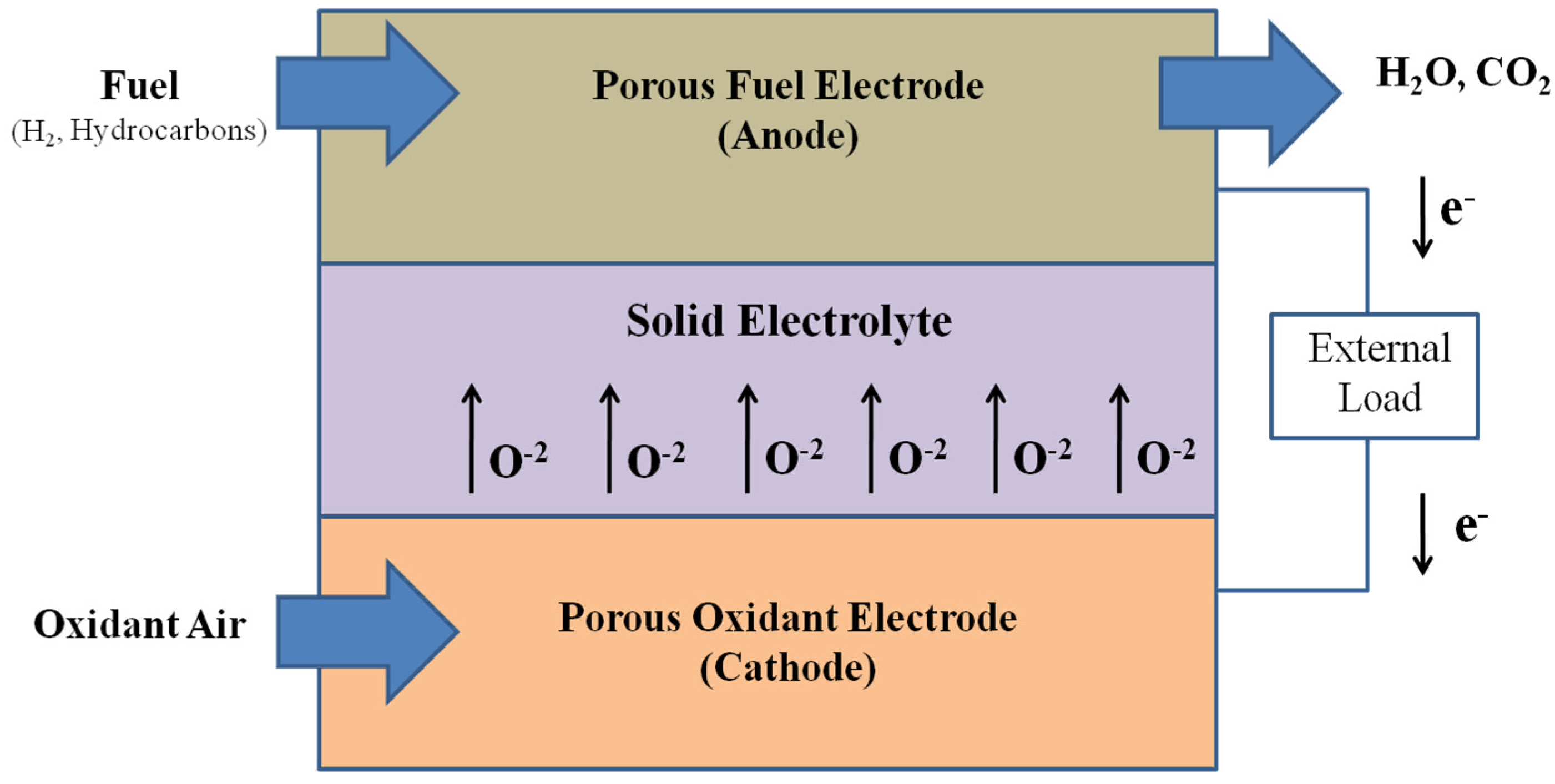
2. Basic Operation of Solid Oxide Fuel Cell
3. Materials
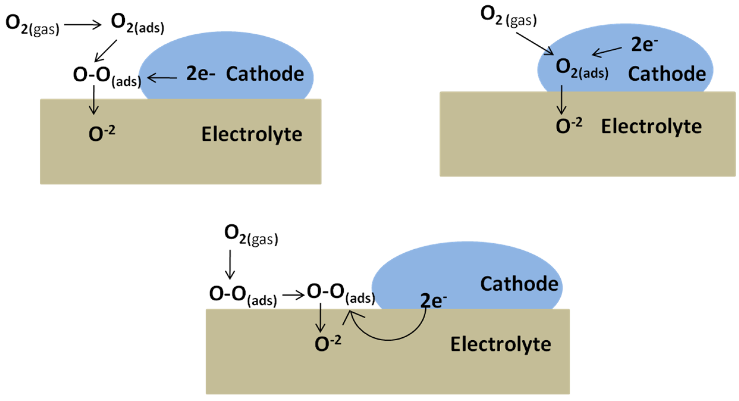
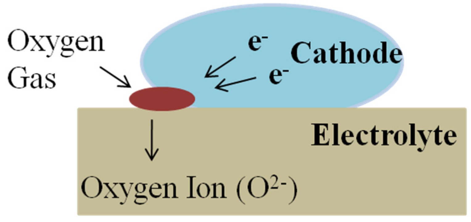
3.1. Cathode
3.2. Electrolyte
3.3. Anode
3.4. Interconnect
3.5. Sealing Materials
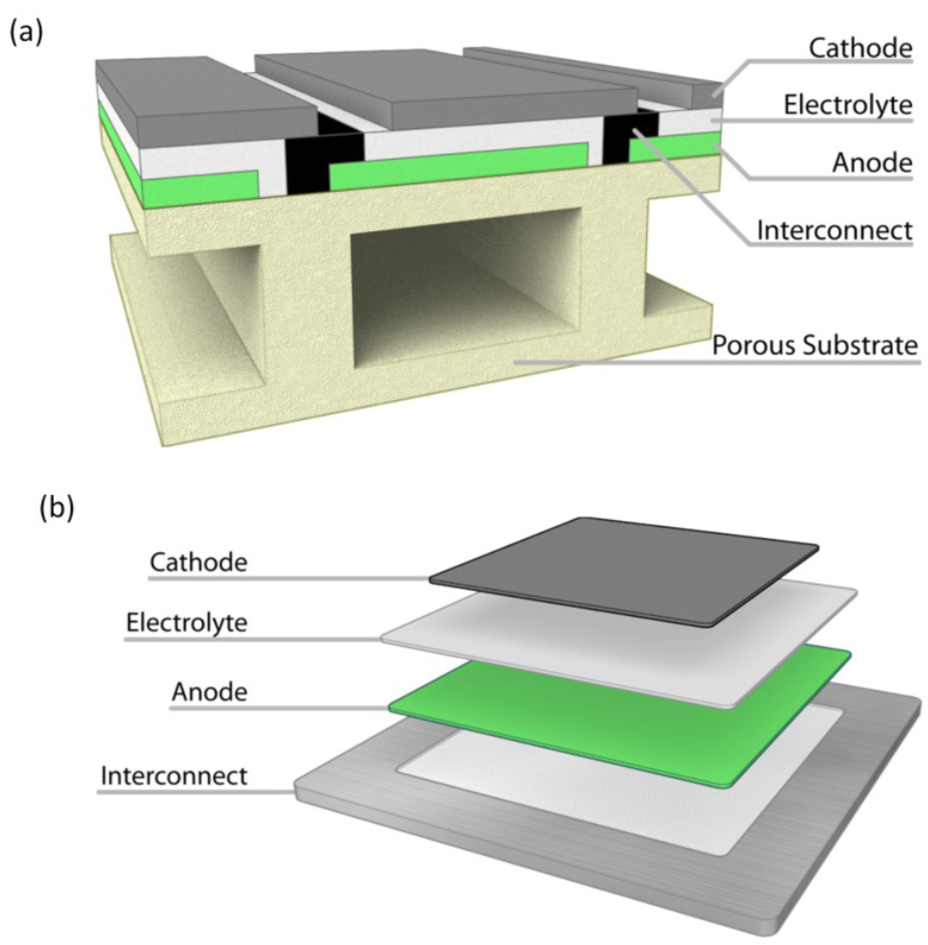
4. Fuel Cell Designs
Cell Design
5. Stack Designs
6. Fabrication Technologies
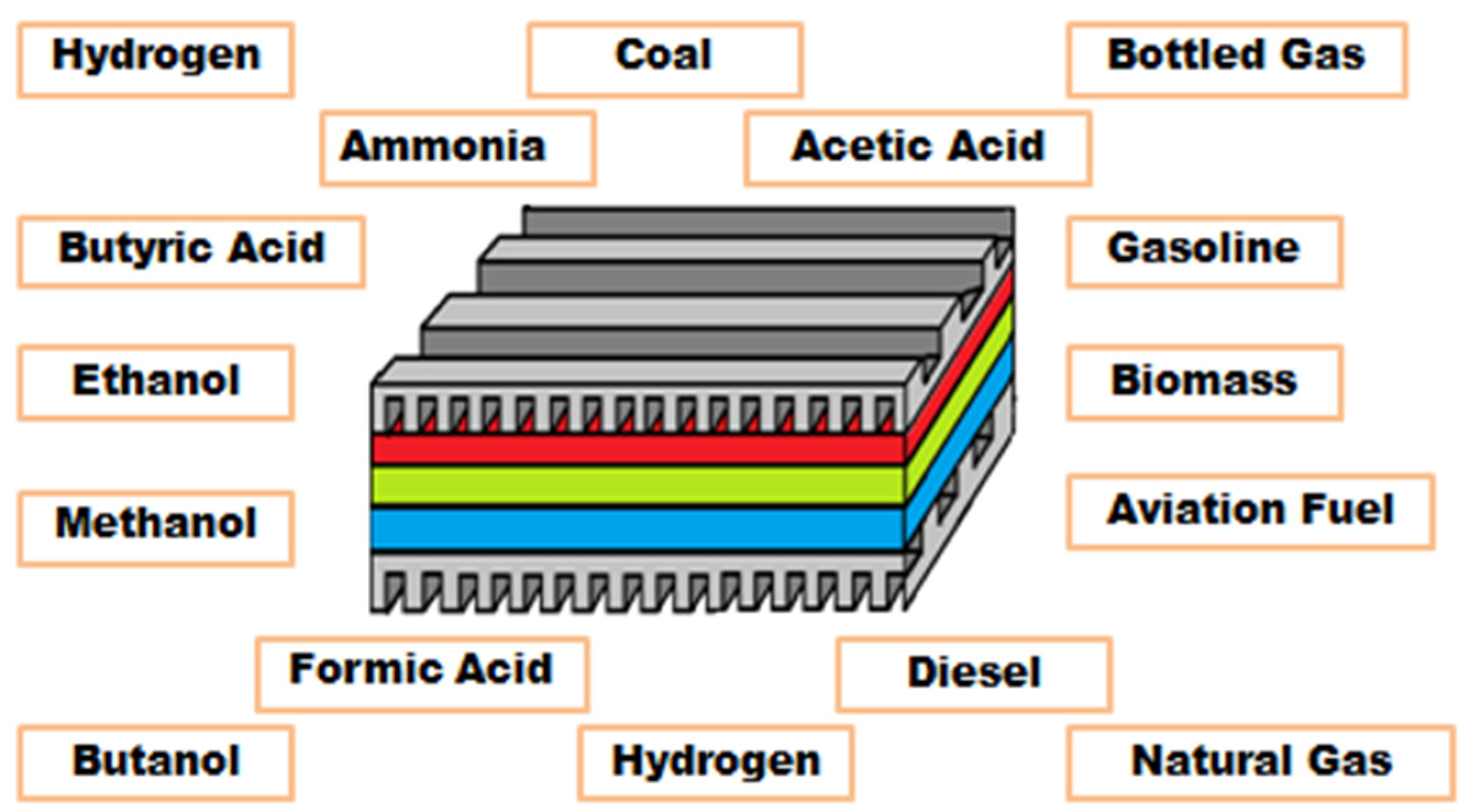
7. SOFC Fuels
8. Performance
9. Challenges on Developing Fuel Cell
10. Summary
Author Contributions
Conflicts of Interest
References
- Stockford, C.; Brandon, N.; Irvine, J.; Mays, T.; Metcalfe, I.; Book, D.; Ekins, P.; Kucernak, A.; Molkov, V.; Steinberger-Wilckens, R.; et al. H2FC SUPERGEN: An overview of the hydrogen and fuel cell research across the UK. Int. J. Hydrogen Energy 2015, 40, 5534–5543. [Google Scholar] [CrossRef]
- Jiang, S.P. Nanoscale and nano-structured electrodes of solid oxide fuel cells by infiltration: Advances and challenges. Int. J. Hydrogen Energy 2012, 37, 449–470. [Google Scholar] [CrossRef]
- World Energy Outlook. Available online: http://www.worldenergyoutlook.org/media/weowebsite/2008-1994/weo2005.pdf (accessed on 20 October 2015).
- Okkay, H.; Bayramoglu, M.; Öksüzömer, M.F. Ce0.8Sm0.2O1.9 synthesis for solid oxide fuel cell electrolyte by ultrasound assisted co-precipitation method. Ultrason. Sonochem. 2013, 20, 978–983. [Google Scholar] [CrossRef] [PubMed]
- Li, C.; Hu, S.; Tay, K.; Fu, Y. Electrochemical characterization of gradient Sm0.5Sr0.5CoO3−δ cathodes on Ce0.8Sm0.2O1.9 electrolytes for solid oxide fuel cells. Ceram. Int. 2012, 38, 1557–1562. [Google Scholar] [CrossRef]
- Giddey, S.; Badwal, S.P.S.; Kulkarni, A.; Munnings, C. A comprehensive review of direct carbon fuel cell technology. Prog. Energy Combust. Sci. 2012, 38, 360–399. [Google Scholar] [CrossRef]
- Zheng, Y.; Zhou, M.; Ge, L.; Li, S.; Chen, H.; Guo, L. Effect of Fe2O3 on Sm-doped ceria system solid electrolyte for IT-SOFCs. J. Alloy. Compd. 2011, 509, 546–550. [Google Scholar] [CrossRef]
- Badwal, S.P.S.; Giddey, S.; Munnings, C.; Kulkarni, A. Review of progress in high temperature solid oxide fuel cells. J. Aust. Ceram. Soc. 2014, 50, 23–37. [Google Scholar]
- Zhang, X.; Chan, S.H.; Li, G.; Ho, H.K.; Li, J.; Feng, Z. A review of integration strategies for solid oxide fuel cells. J. Power Sources 2010, 195, 685–702. [Google Scholar] [CrossRef]
- Sun, C.; Hui, R.; Roller, J. Cathode materials for solid oxide fuel cells: A review. J. Solid State Electrochem. 2010, 14, 1125–1144. [Google Scholar] [CrossRef]
- Quaschning, V. Renewable Energy and Climate Change; CH-13; John Wiley Sons & Ltd.: Hoboken, NJ, USA, 2010. [Google Scholar]
- Fergus, J.; Hui, R.; Li, X.; Wilkinson, D.P.; Zhang, J.J. Solid Oxide Fuel Cells: Materials Properties and Performance; CRC Press: London, UK, 2009. [Google Scholar]
- Ding, D.; Liu, B.; Gong, M.; Liu, X.; Xia, C. Electrical properties of samaria-doped ceria electrolytes from highly active powders. Electrochim. Acta 2010, 55, 4529–4535. [Google Scholar] [CrossRef]
- Guo, Y.; Shi, H.; Ran, R.; Shao, Z. Performance of SrSc0.2Co0.8O3−δ + Sm0.5Sr0.5CoO3−δ mixed-conducting composite electrodes for oxygen reduction at intermediate temperatures. Int. J. Hydrogen Energy 2009, 34, 9496–9504. [Google Scholar] [CrossRef]
- Fu, Y.P.; Wen, S.B.; Lu, C.H. Preparation and characterization of samaria-doped ceria electrolyte materials for solid oxide fuel cells. J. Am. Ceram. Soc. 2008, 91, 127–131. [Google Scholar] [CrossRef]
- Zhu, B.; Liu, X.; Zhu, Z.; Ljungberg, R. Solid oxide fuel cell (SOFC) using industrial grade mixed rare-earth oxide electrolytes. Int. J. Hydrogen Energy 2008, 33, 3385–3392. [Google Scholar] [CrossRef]
- Gu, H.; Chen, H.; Gao, L.; Zheng, Y.; Zhu, X.; Guo, L. Effect of Co doping on the properties of Sr0.8Ce0.2MnO3−δ cathode for intermediate-temperature solid oxide fuel cells. Int. J. Hydrogen Energy 2008, 33, 4681–4688. [Google Scholar] [CrossRef]
- Webe, A.; Ivers-Tiffee, E. Materials and concepts for solid oxide fuel cells (SOFCs) in stationary and mobile applications. J. Power Sources 2004, 127, 273–283. [Google Scholar] [CrossRef]
- Kordesch, K.V.; Simader, G.R. Fuel Cells and Their Applications; Wiley-VCH Verlag GmbH & Co. KGaA: Weinheim, Germany, 1996. [Google Scholar]
- Edwards, P.P.; Kuznetsov, V.L.; David, W.I.F.; Brandon, N.P. Hydrogen and fuel cells: Towards a sustainable energy future. Energy Policy 2008, 36, 4356–4362. [Google Scholar] [CrossRef]
- Nancy, L.G.; Dimitrios, C.P.; Joseph, M.S. Hydrogen and fuel cell technology: Progress, challenges, and future directions. Energy Procedia 2012, 28, 2–11. [Google Scholar]
- Ball, M.; Wietschel, M. The future of hydrogen—Opportunities and challenges. Int. J. Hydrogen Energy 2009, 34, 615–627. [Google Scholar] [CrossRef]
- Adams, T.A., II; Nease, J.; Tucker, D.; Barton, P.I. Energy conversion with solid oxide fuel cell systems: A review of concepts and outlooks for the short- and long-term. Ind. Eng. Chem. Res. 2013, 52, 3089–3111. [Google Scholar] [CrossRef]
- Bhattacharyya, D.; Rengaswamy, R. A review of solid oxide fuel cell (SOFC) dynamic models. Ind. Eng. Chem. Res. 2009, 48, 6068–6086. [Google Scholar] [CrossRef]
- Kilner, J.; Burriel, M. Materials for intermediate-temperature solid-oxide fuel cells. Mater. Res. 2014, 44, 365–393. [Google Scholar] [CrossRef]
- Stambouli, A.B.; Traversa, E. Solid oxide fuel cells (SOFCs): A review of an environmentally clean and efficient source of energy. Renew. Sustain. Energy Rev. 2002, 6, 433–455. [Google Scholar] [CrossRef]
- Singhal, S.C. Solid oxide fuel cells for power generation. WIREs Energy Environ. 2014, 3, 179–194. [Google Scholar] [CrossRef]
- Hajimolana, S.A.; Hussain, M.A.; Ashri Wan Daud, W.M.; Soroush, M.; Shamiri, A. Mathematical modeling of solid oxide fuel cells: A review. Renew. Sustain. Energy Rev. 2011, 15, 1893–1917. [Google Scholar] [CrossRef]
- Coddet, P.; Liao, H.L.; Coddet, C. A review on high power SOFC electrolyte layer manufacturing using thermal spray and physical vapour deposition technologies. Adv. Manuf. 2014, 2, 212–221. [Google Scholar] [CrossRef]
- Badwal, S.P.S. Stability of solid oxide fuel cell components. Solid State Ionics 2001, 143, 39–46. [Google Scholar] [CrossRef]
- Lee, J.H.; Lee, H.W. High Performance Anode Supported Solid Oxide Fuel Cell. U.S. Patent No. 20070015045 A1, 18 January 2007. [Google Scholar]
- Acres, G. Recent advances in fuel cell technology and its applications. J. Power Sources 2001, 100, 60–66. [Google Scholar] [CrossRef]
- Singhal, S.C. Advances in solid oxide fuel cell technology. Solid State Ionics 2000, 135, 305–313. [Google Scholar] [CrossRef]
- Skinner, S.J.; Laguna-Bercero, M.A.; Duncan, W.B.; Walton, R.; O’Hare, D. Advanced inorganic materials for solid oxide fuel cells. In Energy Materials; Wiley-VCH Verlag GmbH & Co. KGaA: Weinheim, Germany, 2011; pp. 33–94. [Google Scholar]
- Jacobson, A.J. Materials for solid oxide fuel cells. Chem. Mater. 2010, 22, 660–674. [Google Scholar] [CrossRef]
- Orera, A.; Slater, P.R. New chemical systems for solid oxide fuel cell. Chem. Mater. 2010, 22, 675–690. [Google Scholar] [CrossRef]
- Ding, D.; Li, X.; Lai, S.Y.; Gerdes, K.; Liu, M. Enhancing SOFC cathode performance by surface modification through infiltration. Energy Environ. Sci. 2014, 7, 552–575. [Google Scholar] [CrossRef]
- Tao, S.W.; Wu, Q.Y.; Peng, D.K.; Meng, G.Y. Electrode materials for intermediate temperature proton-conducting fuel cells. J. Appl. Electrochem. 2000, 30, 153–157. [Google Scholar] [CrossRef]
- Ding, C.; Hashida, T. High performance anode-supported solid oxide fuel cell based on thin-film electrolyte and nanostructured cathode. Energy Environ. Sci. 2010, 3, 1729–1731. [Google Scholar] [CrossRef]
- Chroneos, A.; Parfitt, D.; Kilner, J.A.; Grimes, R.W. Anisotropic oxygen diffusion in tetragonal La2NiO4+δ: Molecular dynamics calculations. J. Mater. Chem. 2010, 20, 266–270. [Google Scholar] [CrossRef]
- Hauch, A.; Ebbesen, S.D.; Jensen, S.H.; Mogensen, M. Highly efficient high temperature electrolysis. J. Mater. Chem. 2008, 18, 2331–2340. [Google Scholar] [CrossRef]
- Belardi, R.M.; Deseure, J.; Brant, M.C.; Matencio, T.; Domingues, R.Z. Electrical study of cathodic activation and relaxation of La0,80Sr0,20MnO3. Ionics 2009, 15, 227–232. [Google Scholar] [CrossRef]
- Laguna-Bercero, M.A. Recent advances in high temperature electrolysis using solid oxide fuel cells: A review. J. Power Sources 2012, 203, 4–16. [Google Scholar] [CrossRef]
- Jiang, S.P. Development of lanthanum strontium manganite perovskite cathode materials of solid oxide fuel cells: A review. J. Mater. Sci. 2008, 43, 6799–6833. [Google Scholar] [CrossRef]
- Brant, M.C.; Matencio, T.; Dessemond, L.; Domingues, R.Z. Electrical and microstructural aging of porous Lanthanum Strontium Manganite/Yttria-doped cubic Zirconia Electrodes. Chem. Mater. 2001, 13, 3954–3961. [Google Scholar] [CrossRef]
- Brant, M.C.; Matencio, T.; Dessemond, L.; Domingues, R.Z. Electrical degradation of porous and dense LSM/YSZ interface. Solid State Ionics 2006, 177, 915–921. [Google Scholar] [CrossRef]
- Dutta, A.; Mukhopadhyay, J.; Basu, R.N. Combustion synthesis and characterization of LSCF-based materials as cathode of intermediate temperature solid oxide fuel cells. J. Eur. Ceram. Soc. 2009, 29, 2003–2011. [Google Scholar] [CrossRef]
- Marina, O.A.; Pederson, L.R.; Williams, M.C.; Coffey, G.W.; Meinhardt, K.D.; Nguyen, C.D.; Thomsen, E.C. Electrode performance in reversible solid oxide fuel cells. J. Elctrochem. Soc. 2007, 154, 452–459. [Google Scholar] [CrossRef]
- Uhlenbruck, S.; Moskalewicz, T.; Jordan, N.; Penkalla, H.J.; Buchkremer, H.P. Element inter diffusion at electrolyte-cathode interfaces in ceramic high-temperature fuel cells. Solid State Ionics 2009, 180, 418–423. [Google Scholar] [CrossRef]
- Holtappels, P.; Vogt, U.; Graule, V.T. Ceramic materials for advanced solid oxide fuel cells. Adv. Eng. Mater. 2005, 7, 292–302. [Google Scholar] [CrossRef]
- Bebelis, S.; Kotsionopoulos, N.; Mai, A.; Tietz, F. Electrochemical characterisation of perovskite-based SOFC cathodes. J. Appl. Electrochem. 2007, 37, 15–20. [Google Scholar] [CrossRef]
- Adijanto, L.; Küngas, R.; Bidrawn, F.; Gorte, R.J.; Vohs, J.M. Stability and performance of infiltrated La0.8Sr0.2CoxFe1−xO3 electrodes with and without Sm0.2Ce0.8O1.9 interlayers. J. Power Sources 2011, 196, 5797–5802. [Google Scholar] [CrossRef]
- Vohs, J.M.; Gorte, R.J. High-performance SOFC cathodes prepared by infiltration. Adv. Mater. 2009, 21, 943–956. [Google Scholar] [CrossRef]
- Huang, Y.; Anh, K.; Vohs, J.M.; Gorte, R.J. Characterisation of Sr-doped LaCoO3-YSZ composites prepared by impregnation methods. J. Electrochem. Soc. 2004, 151, 1592–1597. [Google Scholar] [CrossRef]
- Piao, J.; Sun, K.; Zhang, N.; Chen, X.; Xu, S.; Zhou, D. Preparation and characterisation of Pr1−xSrxFeO3 cathode materials for intermediate temperature solid oxide fuel cells. J. Power Sources 2007, 172, 633–640. [Google Scholar] [CrossRef]
- Zhao, H.; Shen, W.; Zhu, Z.; Li, X.; Wang, Z. Preparation and properties of BaxSr1−xCoyFe1−yO3−δ cathode material for intermediate temperature solid oxide fuel cells. J. Power Sources 2008, 182, 503–509. [Google Scholar] [CrossRef]
- Richter, J.; Holtappels, P.; Graule, T.; Nakamura, T.; Gauckler, L.J. Materials design for perovskite SOFC cathodes. Monatshefte Chem. 2009, 140, 985–999. [Google Scholar] [CrossRef]
- Skinner, S.J.; Munnings, C.N. Electrical properties of iron-substituted La6.4Sr1.6Cu8O20±δ. Mater. Lett. 2002, 57, 594–597. [Google Scholar] [CrossRef]
- Kharton, V.V.; Marques, F.M.B.; Atkinson, A. Transport properties of solid oxide electrolyte ceramics: A brief review. Solid State Ionics 2004, 174, 135–149. [Google Scholar] [CrossRef]
- Chroneos, A.; Yildiz, B.; Tarancón, A.; Parfitt, D.; Kilner, J.A. Oxygen diffusion in solid oxide fuel cell cathode and electrolyte materials: Mechanistic insights from atomistic simulations. Energy Environ. Sci. 2011, 4, 2774–2789. [Google Scholar] [CrossRef]
- Badwal, S.P.S.; Ciacchi, F.T. Oxygen-ion conducting electrolyte materials for solid oxide fuel cells. Ionics 2000, 6, 1–21. [Google Scholar] [CrossRef]
- Rushton, M.J.D.; Chroneos, A.; Skinner, S.J.; Kilner, J.A.; Grimes, R.W. Effect of strain on the oxygen diffusion in yttria and gadolinia co-doped ceria. Solid State Ionics 2013, 230, 37–42. [Google Scholar] [CrossRef]
- Wachsman, E.D.; Lee, K.T. Lowering the temperature of solid oxide fuel cells. Science 2011, 334, 935–939. [Google Scholar] [CrossRef] [PubMed]
- O’Brien, J.E.; Stoots, C.M.; Herring, J.S.; Hartvigsen, J. Hydrogen production performance of 10-cell planar solid-oxide electrolysis stack. J. Fuel Cell Sci. Technol. 2006, 3, 213–219. [Google Scholar] [CrossRef]
- Laguna-Bercero, M.A.; Skinner, S.J.; Kilner, J.A. Performance of solid oxide electrolysis cells based on scandia stablised zirconia. J. Power Sources 2009, 192, 126–131. [Google Scholar] [CrossRef]
- Ishihara, T.; Jirathiwathanakul, N.; Zhong, H. Intermediate temperature solid oxide electrolysis cell using LaGaO3 based perovskite electrolyte. Energy Environ. Sci. 2010, 3, 665–672. [Google Scholar] [CrossRef]
- Ishihara, T.; Kannou, T. Intermediate temperature steam electrolysis using LaGaO3 based electrolyte. Solid State Ionics 2011, 192, 642–644. [Google Scholar] [CrossRef]
- Islam, S.; Hill, J.M. Chapter 4—Anode materials development. In Solid Oxide Fuel Cells: From Materials to System Modeling: The Royal Society of Chemistry; RSC Publishing: London, UK, 2013. [Google Scholar]
- Fergus, J.W. Oxide anode materials for solid oxide fuel cells. Solid State Ionics 2006, 177, 1529–1541. [Google Scholar] [CrossRef]
- Zhu, W.Z.; Deevi, S.C. A review on the status of anode materials for solid oxide fuel cells. Mater. Sci. Eng. 2003, 362, 228–239. [Google Scholar] [CrossRef]
- Martins, R.F.; Brant, M.C.; Domingues, R.Z.; Paniago, R.M.; Sapag, K.; Matencio, T. Synthesis and characterization of NiO-YSZ for SOFCs. Mater. Res. Bull. 2009, 44, 451–456. [Google Scholar] [CrossRef]
- Sun, C.; Stimming, U. Recent anode advances in solid oxide fuel cells. J. Power Sources 2007, 171, 247–260. [Google Scholar] [CrossRef]
- Lee, J.H.; Moon, H.; Lee, H.W.; Kim, J.; Kim, J.D.; Yoon, K.H. Quantitative analysis of microstructure and its related electrical property of SOFC anode. Solid State Ionics 2002, 148, 15–26. [Google Scholar] [CrossRef]
- Jiang, S.P.; Callus, P.J.; Badwal, S.P.S. Fabrication and performance of Ni/3 mol % Y2O3–ZrO2 cermet anodes for solid oxide fuel cells. Solid State Ionics 2000, 132, 1–14. [Google Scholar] [CrossRef]
- Liu, Y.L.; Primdahl, S.; Mogensen, M. Effects of impurities on microstructure in Ni/YSZ–YSZ half-cells for SOFC. Solid State Ionics 2003, 161, 1–10. [Google Scholar] [CrossRef]
- Tietz, F.; Buchkremer, H.P.; Stover, D. Components manufacturing for solid oxide fuel cells. Solid State Ionics 2002, 152, 373–381. [Google Scholar] [CrossRef]
- McIntosh, S.; Gorte, R.J. Direct hydrocarbon solid oxide fuel cells. Chem. Rev. 2004, 104, 4845–4865. [Google Scholar] [CrossRef] [PubMed]
- Kulkarni, A.; Ciacchi, F.T.; Giddey, S.; Munnings, C.; Badwal, S.P.S.; Kimpton, J.A.; Fini, D. Mixed ionic electronic conducting perovskite anode for direct carbon fuel cells. Int. J. Hydrogen Energy 2012, 37, 19092–19102. [Google Scholar] [CrossRef]
- Goodenough, J.B.; Huang, Y.H. Alternative anode materials for solid oxide fuel cells. J. Power Sources 2007, 173, 1–10. [Google Scholar] [CrossRef]
- Vulliet, J.; Morel, B.; Laurencin, J.; Gauthier, G.; Bianchi, L.; Giraud, S.; Henry, H.Y.; Lefebvre-Joud, F. First results on a (La,Sr)CrO3 anode fed with methane. Electrochem. Soc. Proc. 2003, 2003, 803–811. [Google Scholar]
- Tao, S.; Irvine, J.T.S. A Redox-stable efficient anode for solid-oxide fuel cells. Nat. Mater. 2003, 2, 320–323. [Google Scholar] [CrossRef] [PubMed]
- Vernoux, P.; Guillodo, M.; Fouletier, J.; Hammou, A. Alternative anode material for gradual methane reforming in solid oxide fuel cells. Solid State Ionics 2000, 135, 425–431. [Google Scholar] [CrossRef]
- Huang, Y.; Dass, R.I.; Xing, Z.; Goodenough, J.B. Double perovskites as anode materials for solid-oxide fuel cells. Science 2006, 312, 254–257. [Google Scholar] [CrossRef] [PubMed]
- Yang, C.; Yang, Z.; Jin, C.; Xiao, G.; Chen, F.; Han, M. Sulfur-tolerant redox-reversible anode material for direct hydrocarbon solid oxide fuel cells. Adv. Mater. 2012, 24, 1439–1443. [Google Scholar] [CrossRef] [PubMed]
- Atkinson, A.; Barnett, S.; Gorte, R.J.; Irvine, J.T.S.; McEvoy, A.J.; Mogensen, M.; Singhal, S.C.; Vohs, J. Review of anode materials development in solid oxide fuel cells. Nat. Mater. 2004, 3, 17–27. [Google Scholar] [CrossRef] [PubMed]
- Lia, X.; Zhao, H.; Xu, N.; Zhou, X.; Zhang, C.; Chen, N. Electrical conduction behavior of La, Co co-doped SrTiO3 perovskite as anode material for solid oxide fuel cells. Int. J. Hydrogen Energy 2009, 34, 6407–6414. [Google Scholar] [CrossRef]
- Badwal, S.P.S.; Deller, R.; Foger, K.; Ramprakash, Y.; Zhang, J.P. Interaction between chromia forming alloy interconnects and air electrode of solid oxide fuel cells. Solid State Ionics 1997, 99, 297–310. [Google Scholar] [CrossRef]
- Fontana, S.; Amendola, R.; Chevalier, S.; Piccardo, P.; Caboche, G.; Viviani, M.; Molins, R.; Sennour, M. Metallic interconnects for SOFC: Characterization of corrosion resistance and conductivity evaluation at operating temperature of differently coated alloys. J. Power Sources 2007, 171, 652–662. [Google Scholar] [CrossRef]
- Fergus, J.W. Lanthanum chromite-based materials for solid oxide fuel cell interconnects. Solid State Ionics 2004, 171, 1–15. [Google Scholar] [CrossRef]
- Yoon, K.J.; Cramer, C.N.; Stevenson, J.W.; Marina, A. Advanced ceramic interconnect materials for solid oxide fuel cells: Electrical and thermal properties of calcium- and nickel-doped yttrium chromites. J. Power Sources 2010, 195, 7587–7593. [Google Scholar] [CrossRef]
- Shaigan, N.; Qu, W.; Ivey, D.G.; Chen, W. A review of recent progress in coatings, surface modifications and alloy developments for solid oxide fuel cell ferritic stainless steel interconnects. J. Power Sources 2010, 195, 1529–1542. [Google Scholar] [CrossRef]
- Yang, Z. Recent Advances in metallic interconnects for solid oxide fuel cells. Int. Mater. Rev. 2008, 53, 39–54. [Google Scholar] [CrossRef]
- Wu, J.; Liu, X. Recent development of SOFC metallic interconnect. J. Mater. Sci. Technol. 2010, 26, 293–305. [Google Scholar] [CrossRef]
- Gaillard, F.; Joly, J.; Boreave, A.; Vernoux, P.; Deloume, J. Intermittent temperature-programmed desorption study of perovskites used for catalytic purposes. Appl. Surf. Sci. 2007, 253, 5876–5881. [Google Scholar] [CrossRef]
- Zhu, J.; Zhang, Y.; Basu, A.; Lu, Z.; Paranthaman, M.; Lee, D.; Payzant, E. LaCrO3-based coatings on ferritic stainless steel for solid oxide fuel cell interconnect applications. Surf. Coat. Technol. 2004, 65, 177–178. [Google Scholar] [CrossRef]
- Larring, Y.; Norby, T. Spinel and perovskite functional layers between plan see metallic interconnect (Cr-5 wt % Fe-1 wt % Y2O3) and ceramic (La0.85Sr0.15)0.91 MnO3 cathode materials for solid oxide fuel cells. J. Electrochem. Soc. 2000, 147, 3251–3256. [Google Scholar] [CrossRef]
- Chen, X.; Hou, P.; Jacobson, C.; Visco, S.J.; de Jonghe, L.C. Protective coating on stainless steel interconnect for SOFCs: Oxidation kinetics and electrical properties. Solid State Ionics 2005, 176, 425–433. [Google Scholar] [CrossRef]
- Yang, Z.; Xia, G.; Simner, S.; Stevenson, J. Thermal growth and performance of manganese cobaltite spinel protection layers on ferritic stainless steel SOFC interconnects. J. Electrochem. Soc. 2005, 152, 1896–1901. [Google Scholar] [CrossRef]
- Yang, Z.; Xia, G.; Li, X.; Stevenson, J. (Mn,Co)3O4 spinel coatings on ferritic stainless steels for SOFC interconnect applications. Int. J. Hydrogen Energy 2007, 32, 3648–3654. [Google Scholar] [CrossRef]
- Weil, K.S. The state-of-the-art in sealing technology for solid oxide fuel cells. J. Mater. 2006, 58, 37–44. [Google Scholar] [CrossRef]
- Rautanen, M.; Pulkkinen, V.; Tallgren, J.; Himanen, O.; Kiviaho, J. Effects of the first heat up procedure on mechanical properties of solid oxide fuel cell sealing materials. J. Power Sources 2015, 284, 511–516. [Google Scholar] [CrossRef]
- Stolten, D. Fuel Cell Science and Engineering: Materials, Processes, Systems and Technology; Wiley: Hoboken, NJ, USA, 2012. [Google Scholar]
- Singhal, S.C.; Kendal, K. High-Temperature Solid Oxide Fuel Cells: Fundamentals, Design and Applications; Elsevier: Philadelphia, PA, USA, 2003. [Google Scholar]
- Timurkutluk, B.; Timurkutluk, C.; Mat, M.D.; Kaplan, Y. Development of high-performance anode supported solid oxide fuel cell. Int. J. Energy Res. 2012, 36, 1383–1387. [Google Scholar] [CrossRef]
- Badwal, S.P.S.; Foger, K. Solid oxide electrolyte fuel cell review. Ceram. Int. 1996, 22, 257–265. [Google Scholar] [CrossRef]
- Lee, S.; Bevilacqua, M.; Fornasiero, P.; Vohs, J.M.; Gorte, R.J. Solid oxide fuel cell cathodes prepared by infiltration of LaNi0.6Fe0.4O3 and La0.91Sr0.09Ni0.6Fe0.4O3 in porous yttria-stabilized zirconia. J. Power Sources 2009, 193, 747–753. [Google Scholar] [CrossRef]
- Huang, K.; Singhal, S.C. Cathode-supported tubular solid oxide fuel cell technology: A critical review. J. Power Sources 2013, 237, 84–97. [Google Scholar] [CrossRef]
- Marozau, I.P.; Kharton, V.V.; Viskup, A.P.; Frade, J.R.; Samakhval, V.V. Electronic conductivity, oxygen permeability and thermal expansion of Sr0.7Ce0.3Mn1−xAlxO3−δ. J. Eur. Ceram. Soc. 2006, 26, 1371–1378. [Google Scholar] [CrossRef]
- Roehrens, D.; Han, F.; Haydn, M.; Schafbauer, W.; Sebold, D.; Menzler, N.H.; Buchkremer, H.M. Advances beyond traditional SOFC cell designs. Int. J. Hydrogen Energy 2015, 40, 11538–11542. [Google Scholar] [CrossRef]
- Agnew, G.D.; Collins, R.D.; Jorger, M.; Pyke, S.H.; Travis, R.P. The components of a rolls-royce 1 MW SOFC system. ECS Trans. 2007, 7, 105–111. [Google Scholar]
- Taroco, H.A.; Santos, J.A.F.; Domingues, R.Z.; Matencio, T. Ceramic Materials for Solid Oxide Fuel Cells, Advances in Ceramics—Synthesis and Characterization, Processing and Specific Applications; Costas, S., Ed.; INTECH Open Access Publisher: Rijeka, Croatia, 2011. [Google Scholar]
- Badwal, S.P.S.; Giddey, S.; Munnings, C. Hydrogen production via solid electrolytic routes. WIREs Energy Environ. 2013, 2, 473–487. [Google Scholar] [CrossRef]
- Lu, Z.; Zhou, X.D.; Fisher, D.; Templeton, J.; Stevenson, J.; Wu, N.; Ignatiev, A. Enhanced performance of an anode-supported YSZ thin electrolyte fuel cell with a laser-deposited Sm0.2Ce0.8O1.9 interlayer. Electrochem. Commun. 2010, 12, 179–182. [Google Scholar] [CrossRef]
- EG & G Technical Services. Fuel Cell Handbook, 5th ed.; Parsons, Inc.: Morgan, WV, USA, 2000. [Google Scholar]
- Perednis, D.; Gauckler, L.J. Solid oxide fuel cells with electrolytes prepared via spray pyrolysis. Solid State Ionics 2004, 166, 229–239. [Google Scholar] [CrossRef]
- Santillán, M.J.; Caneiro, A.; Quaranta, N.; Boccaccini, A.R. Electrophoretic deposition of La0.6Sr0.4Co0.8Fe0.2O3−δ cathodes on Ce0.9Gd0.1O1.95 substrates for intermediate temperature solid oxide fuel cell (IT-SOFC). J. Eur. Ceram. Soc. 2009, 29, 1125–1132. [Google Scholar] [CrossRef]
- Matsuda, M.; Hosomia, T.; Murata, K.; Fukui, T.; Miyake, M. Fabrication of bilayered YSZ/SDC electrolyte film by electrophoretic deposition for reduced-temperature operating anode-supported SOFC. J. Power Sources 2007, 165, 102–107. [Google Scholar] [CrossRef]
- Ding, J.; Liu, J. An anode-supported solid oxide fuel cell with spray-coated yttria-stabilized zirconia (YSZ) electrolyte film. Solid State Ionics 2008, 179, 1246–1249. [Google Scholar] [CrossRef]
- Murata, K.; Fukui, T.; Abe, H.; Naito, M.; Nogi, K. Morphology control of La(Sr)Fe(Co)O3−a cathodes for IT-SOFCs. J. Power Sources 2005, 145, 257–261. [Google Scholar] [CrossRef]
- Fan, B.; Liu, X. A-deficit LSCF for intermediate temperature solid oxide fuel cells. Solid State Ionics 2009, 180, 973–977. [Google Scholar] [CrossRef]
- Chen, J.; Liang, F.; Yan, D.; Pu, J.; Chi, B.; Jiang, S.P.; Jian, L. Performance of large-scale anode-supported solid oxide fuel cells with impregnated La0.6Sr0.4Co0.2Fe0.8O3−δ + Y2O3 stabilized ZrO2 composite cathodes. J. Power Sources 2010, 195, 5201–5205. [Google Scholar] [CrossRef]
- Liu, J.; Barnett, S.A. Thin Yttrium Stabilized zircônia electrolyte solid oxide fuel cells by centrifuge casting. J. Am. Ceram. Soc. 2002, 85, 3096–3098. [Google Scholar] [CrossRef]
- Tietz, F.; Haanappel, V.A.C.; Maim, A.; Mertens, J.; Stöver, D. Performance of LSCF cathodes in cell tests. J. Power Sources 2006, 156, 20–22. [Google Scholar] [CrossRef]
- Savaniu, C.D.; Irvine, J.T.S. La-doped SrTiO3 as anode material for IT-SOFC. Solid State Ionics 2011, 192, 491–493. [Google Scholar] [CrossRef]
- Yoo, K.B.; Choi, G.M. Performance of La-doped strontium titanate (LST) anode on LaGaO3-based SOFC. Solid State Ionics 2009, 180, 867–871. [Google Scholar] [CrossRef]
- Liu, Y.; Hashimoto, S.; Nishino, H.; Takei, K.; Mori, M. Fabrication and characterization of a co-fired La0.6Sr0.4Co0.2Fe0.8O3−δ cathode-supported Ce0.9Gd0.1O1.95 thin-film for IT-SOFCs. J. Power Sources 2007, 164, 56–64. [Google Scholar] [CrossRef]
- Hibino, T.; Hashimoto, A.; Yano, M.; Suzuki, M.; Sano, M. Ru-catalyzed anode materials for direct hydrocarbon SOFCs. Electrochim. Acta 2003, 48, 2531–2537. [Google Scholar] [CrossRef]
- Sin, A.; Kopnin, E.; Dubitsky, Y.; Zaopo, A.; Aricò, A.S.; Gullo, L.R.; La Rosa, D.; Antonucci, V. Stabilisation of composite LSFCO–GDC based anodes for methane oxidation in solid oxide fuel cells. J. Power Sources 2005, 145, 68–73. [Google Scholar] [CrossRef]
- Ruiz-Morales, J.C.; Canales-Vázquez, J.; Peña-Martínez, J.; López, D.M.; Núñez, P. On the simultaneous use of La0.75Sr0.25Cr0.5Mn0.5O3−δ as both anode and cathode material with improved microstructure in solid oxide fuel cells. Electrochem. Acta 2006, 52, 278–284. [Google Scholar] [CrossRef]
- Behling, N.H. Fuel Cells: Current Technology Challenges and Future Research Needs; Elsevier: Philadelphia, PA, USA, 2013. [Google Scholar]
- Steele, B.C.H.; Heinzel, A. Materials for fuel-cell technologies. Nature 2001, 414, 345–352. [Google Scholar] [CrossRef] [PubMed]
- Wachsman, E.D.; Marlowe, C.A.; Lee, K.T. Role of solid oxide fuel cells in a balanced energy strategy. Energy Environ. Sci. 2012, 5, 5498–5509. [Google Scholar] [CrossRef]
- Suzuki, T.; Hasan, Z.; Funahashi, Y.; Yamaguchi, T.; Fujishiro, Y.; Awano, M. Impact of anode microstructure on solid oxide fuel cells. Science 2009, 325, 852–855. [Google Scholar] [CrossRef] [PubMed]
- Herring, J.S.; O’Brien, J.E.; Stoots, C.M.; Hawkes, G.L.; Hartvigsen, J.J.; Shahnam, M. Progress in high-temperature electrolysis for hydrogen production using planar SOFC technology. Int. J. Hydrogen Energy 2007, 32, 440–450. [Google Scholar] [CrossRef]


| Fuel Cell | Operating Temperature (°C) | Power (kW) | Efficiency (%) | Application |
|---|---|---|---|---|
| PEM (Polymer Electrolyte Membrane) | 60–110 | 0.01–250 | 40%–55% | Portable, Mobile, Low power generation. |
| AFC (Alkaline Fuel Cell) | 70–130 | 0.1–50 | 50%–70% | Mobile, space, military. |
| PAFC (Phosphoric Acid Fuel Cell) | 175–210 | 50–1000 | 40%–45% | Medium to large scale power generation and CHP (Combined Heat and Power). |
| MCFC (Molten Carbonate Fuel Cell) | 550–650 | 200–100,000 | 50%–60% | Large scale power generation. |
| SOFC (Solid Oxide Fuel Cell) | 500–1000 | 0.5–2000 | 40%–72% | Vehicle auxiliary power units, medium to large scale power generation and CHP, off-grid power and micro CHP. |
| DMFC (Direct Methanol Fuel Cell) | 70–130 | 0.001–100 | 40% | Mobile, portable. |
| Cathode | σe (S·cm−1) | σi (S·cm−1) | T (°C) |
|---|---|---|---|
| LSM | <200 | <4 × 10⁻⁸ | 800 |
| LSC | 1600 | 0.4 | 800 |
| LSF | >50 | 5 × 10⁻³ | 800 |
| LSCF | 230 | 0.2 | 900 |
| PSF | 300, 78 | - | 550, 800 |
| BSCF | 45, 20 | - | 500, 800 |
| LSCu | 500 | - | 800 |
| Anode | σe (S·cm−1) | Rp (Ω-cm2) | Temperature (°C) |
|---|---|---|---|
| Y0.3Ce0.7O2−δ | 10 | 0.1 | 900 |
| La0.4Sr0.6TiO3 | ~360 | 0.7 | 800 |
| La0.35Sr0.65TiO3-Ce0.7La0.3O2 (7:3 mol ratio) | 40 | 0.2–0.4 | 800 |
| La0.25Sr0.75Cr0.5Mn0.5O3 | 3 | 0.1–0.3 | 800 |
| Sr0.88Y0.08TiO3 | 64 | 1–10 | 800 |
| Pr0.4Sr0.6Co0.2Fe0.7Nb0.1O3−δ | - | 0.16 | 900 |
| Y0.2Zr0.62Ti0.18O1.9 | 0.15 | 1–10 | 800 |
| La0.6Sr0.4Fe0.9Mn0.1O3 + 2 wt % Pd | - | 0.8 in CH4 | 800 |
| YSZ-40 wt % CeO2 + 1 wt % Pd | - | 0.26 | 900 |
| Deposition Technique | Concise Description | Common Applications | Features | References |
|---|---|---|---|---|
| Screen printing | The prepared suspension is placed on the screen and is forced by pressure for its passage. | Electrolyte, anode and cathode | Scale-up is easily feasible. Formation of cracks take place in some ceria based electrolytes and has improper densification. | [12,103,113] |
| Tape casting | Deposition of ceramic film is done temporary support consisting of mobile sheet. Doctor blade device is used to have desired thickness. | Electrolyte and anode | Scale-up is easily feasible, multilayer cells production, Electrolytes with various thicknesses can be produced. No suitable for large cell areas. | [12,103,114] |
| Atmospheric Plasma spray (APS) | Plasma jet (~10,000 K) is used to melt particles which are then sprayed over the substrate with quick solidification. | Electrolyte, anode, cathode and inter connector | Rapid deposition, Films having varying microstructure and compositions can be produced, SOFC layers can be deposited without sintering on metallic substrates, scale-up is easily feasible. | [12,103] |
| Spray Pyrolyse | A suspension comprised of powder is sprayed on hot substrate followed by sintering in order to deposit a film. | Electrolyte | Thin and impermeable electrolytes, gradient layer can be produced by changing the solution | [12,103,115] |
| Colloidal sprayed position (CSD) | A colloidal solution is pumped to liquid dispersing apparatus, like an ultrasonic nozzle on hot substrate. | Electrolyte and cathode | Low cathode ASR(area specific resistance), increasing in power density. | [12] |
| Chemical vapored position (CVD) | Deposition takes place by gas phase reaction between metal halide precursors and a hot substrate. | Cathode and Electrolyte | Electrolyte thin film Low deposition, high temperatures needed, high apparatus costs, corrosive products. | [12,116] |
| Electrochemical vapored position (EVD) | Metal chloride vapors and water vapor or oxygen are placed on either side of the substrate in a chamber. Due to reaction between the metal chloride and water vapor, closure of pores takes palce and then film growth takes place due to formation of an electrochemical potential gradient | Tubular cells electrolytes and interconnect | Dense film can be deposited on porous substrate; can be used for tubular substrate, homogeneous films having good mechanical properties can be obtained, Low sintering. temperature, High SOFC’s cost, high temperature needed for rapid deposition | [12,103] |
| Spin coating | Film can be produced by spinning a sol gel precursor on porous or dense substrate. The thickness of the film can be controlled by stir rate | Electrolyte | Dense and thin electrolyte can be obtained | [12,103,114] |
| Dip coating or Slurry coating | The substrate is dipped in an alcoholic or aqueous or suspension which is then dried at room temperature. After that it is preheated this is then followed by sintering. The procedure is repeated again and again | Electrolyte, anode and cathode | It is low cost method but time consuming | [12,103,116,117] |
| Tape calendaring | It is analogous to tape casting, but spacing between rollers is used to control the thickness. The deposited suspension is a thermoplastic material. | Anode and electrolyte | Electrolyte with varying thickness is possible, multilayer cells can be produced. | [12,103,114] |
| Sputtering | Noble gas ions usually argon ions are used to bombard the target material. After that, atoms or ions of the targeted material are released and deposited on the substrate. | Electrolyte, anode and cathode | Thin electrolyte films are attainable; Morphology and composition can be controlled; Low temperature for deposition. Ceria films can be cracked; high cost; Techniques like radio-frequency (RF)sputtering and direct current (DC)sputtering are time consuming | [12,103] |
| Electrophoretic deposition (EPD) | An electric field is applied forcing charged particles suspended in a liquid to move toward an electrode with opposite charge. | Electrolyte and cathode | Easy operation; homogeneous films, effortless deposition on complex forms substrates; controlled film thickness, scale-up is easily feasible; cheaper option to deposit electrolyte on tubular cathode. | [12,103,116,117] |
| Pulsed-laser deposition (PLD) or laser ablation) | Laser ablation of material is done in vacuum which is then deposited on substrate at temperature of about 700 °C | Electrolyte and cathode | Miniaturized SOFC can be produced, have potential for automation, nano structures can be formed | [12] |
| Sol Gel | The salts of required cations are dissolved to form solution. The colloid is then dried to obtain a powder that is deposited by conventional methods or it is partially dried to yield viscous slurry that is deposited by a wet method. | Electrolyte | High sintering temperature is not needed | [12] |
| Painting | The suspension is deposited by a paintbrush on substrate. | Electrolyte, anode and cathode | Easy method, scale up is hard, not reproducible. | [12] |
| Anode | Cathode | Electrolyte | Fuel | Max. Power Density (mW·cm−2) | Temperature (°C) | Reference |
|---|---|---|---|---|---|---|
| NiO-YSZ (support cell) | La0.6Sr0.4Co0.2Fe0.8O3−δ (30 μm) | ZrO2/Y2O3 (4 μm) + SDC (1 μm) | H2 (3 wt. % H2O) | 600 | 700 | [117] |
| NiO-YSZ (0.5 mm) | La0.7Sr0.3MnO3/YSZ | ZrO2/Y2O3 (14.9 μm) | H2 (3 wt. % H2O) | 990 | 800 | [118] |
| NiO-YSZ (support cell) | La0.6Sr0.4Co0.2Fe0.8O3−δ | ZrO2/Y2O3 (0.2 mm) | H2 (3 wt. % H2O) | 500 | 700 | [119] |
| NiO-YSZ 0.8 mm | La0.54Sr0.44Co0.2Fe0.8O3−δ (6 μm) | ZrO2/Y2O3 (8 μm) | H2 | 855 | 700 | [120] |
| NiO-YSZ (support cell) | La0.6Sr0.4Co0.2Fe0.8O3−δ /Y2O3/YSZ2 | YSZ dense + YSZ porous (9μm) | H2 | 473 | 750 | [121] |
| NiO-YSZ (0.5 mm) | La0.6Sr0.4Co0.2Fe0.8O3−δ/Ce0.9Gd0.1O1.95 | ZrO2/Y2O325 μm | H2 (3 wt. % H2O) | 930 | 800 | [122] |
| NiO-YSZ (1.5 mm) | La0.58Sr0.4Co0.2Fe0.8O3−δ (45 μm) | ZrO2/Y2O3Ce0.8Gd0.2O2−δ Interlayer | H2 (3 wt. % H2O) | 1230 | 800 | [123] |
| La0.2Sr0.7TiO3 | La0.6Sr0.4CoO3 | ZrO2/Y2O3 (50–75 μm) | H2 (3 wt. % H2O) | 500 | 750 | [124] |
| La0.2Sr0.8TiO3 (~15 μm) | La0.6Sc0.4Co0.2Fe0.8O3 (~15 μm) | La0.9Sr0.1Ga0.8M g0.2O3 (~600 μm support cell) | H2 (3 wt. % H2O) | 300 | 800 | [125] |
| NiO/GDC: NiO-Ce0.9Gd0.1O1.95 | La0.6Sr0.4Co0.2Fe0.8O3−δ/Ce0.9Gd0.1O1.95 (2mm support cell) | Ce0.9Gd0.1O1.95 (thickness: <20μm) | H2 (3 wt. % H2O) | 35 (550 °C) and 60 (600 °C) | 550 and 600 | [126] |
| NiO/Ce0.9Gd0.1O1.95/RuO2 (1.0mm) | Sm0.5Sr0.5CoO3 | Ce0.9Gd0.1O1.95 (25–40 μm) | Methane/Ethane/propaNe | 750 (methane), 716(ethane), 648(propane) | 600 | [127] |
| La0.6Sr0.4Fe0.8Co0.2O3/Ce0.8Gd0.2 O1.9 | La0.6Sr0.4Fe0.8Co0.2O3 (5 μm) | Ce0.8Gd0.2O1.9 (300 μm support cell) | Methane | 170 | 800 | [128] |
| La0.75Sr0.25Cr0.5Mn0.5O3−δ | La0.75Sr0.25Cr0.5Mn0.5O3−δ | ZrO2/Y2O3 (1.6 mm) | Hydrogen/methane | 300 (CH4) and 500 (H2) | 950 | [129] |
© 2016 by the authors; licensee MDPI, Basel, Switzerland. This article is an open access article distributed under the terms and conditions of the Creative Commons by Attribution (CC-BY) license (http://creativecommons.org/licenses/by/4.0/).
Share and Cite
Irshad, M.; Siraj, K.; Raza, R.; Ali, A.; Tiwari, P.; Zhu, B.; Rafique, A.; Ali, A.; Kaleem Ullah, M.; Usman, A. A Brief Description of High Temperature Solid Oxide Fuel Cell’s Operation, Materials, Design, Fabrication Technologies and Performance. Appl. Sci. 2016, 6, 75. https://doi.org/10.3390/app6030075
Irshad M, Siraj K, Raza R, Ali A, Tiwari P, Zhu B, Rafique A, Ali A, Kaleem Ullah M, Usman A. A Brief Description of High Temperature Solid Oxide Fuel Cell’s Operation, Materials, Design, Fabrication Technologies and Performance. Applied Sciences. 2016; 6(3):75. https://doi.org/10.3390/app6030075
Chicago/Turabian StyleIrshad, Muneeb, Khurram Siraj, Rizwan Raza, Anwar Ali, Pankaj Tiwari, Bin Zhu, Asia Rafique, Amjad Ali, Muhammad Kaleem Ullah, and Arslan Usman. 2016. "A Brief Description of High Temperature Solid Oxide Fuel Cell’s Operation, Materials, Design, Fabrication Technologies and Performance" Applied Sciences 6, no. 3: 75. https://doi.org/10.3390/app6030075
APA StyleIrshad, M., Siraj, K., Raza, R., Ali, A., Tiwari, P., Zhu, B., Rafique, A., Ali, A., Kaleem Ullah, M., & Usman, A. (2016). A Brief Description of High Temperature Solid Oxide Fuel Cell’s Operation, Materials, Design, Fabrication Technologies and Performance. Applied Sciences, 6(3), 75. https://doi.org/10.3390/app6030075