1. Introduction
In recent years, growing concerns regarding environmental pollution have recently increased the demand for green vehicles. Green vehicles include electric vehicles, natural gas vehicles, fuel cell vehicles (FCV), and vehicles running on fuels such as a bio diesel or an ethanol blend. Fuel cell vehicles are driven by electric power made through electrochemical reactions between hydrogen and oxygen that generate water. These vehicles do not emit any contaminants such as CO
2, HC and NOx since the operation principles of fuel cells do not include any combustion reaction. These vehicles show very high energy conversion efficiency because they do not use any driving part that makes reciprocating motions, such as pistons in engines. However, to extend their range and secure their competitiveness against other fuels, the storage capacity of hydrogen gas needs to be increased by compressing it up to an ultra-high pressure of 700 bar [
1,
2].
When storing and using fuel at ultra-high pressure, securing the safety of the cylinder and cylinder valves is very important. For the safety of the cylinder, a high-strength aluminum liner used as an internal vessel, was produced by extrusion and auto frettage processes and then laminated with carbon fiber on the outer wall [
3]. The cylinder valve is the main component of the cylinder in the fuel control system of the FCV. It is composed of a manual manipulation device for opening and closing the flow path, a solenoid actuator, a temperature sensitized pressure relief device, and an overflow blocking device to secure safety against leakage and fire.
Solenoid actuators are energy conversion devices that first convert electric input signals into electromagnetic energy through a coil and output mechanical kinetic energy to open and close the flow path through a magnetic pole formed by a core and plunger [
4]. Solenoid actuators have been widely used for their good performance of simple structure, fast response, energy conservation, economic feasibility, and favorable stability. As an emerging process in the automobile industry, electronic fuel injection systems of internal combustion engine are using solenoid actuators for reduction of fuel consumption and hazardous exhaust emissions [
5,
6]. There are growing demands for high frequency response, reduction of actuation forces, and strong anti-pollution capabilities of electro hydraulic control system [
7,
8].
In the case of solenoid actuators, for the cylinder valve of the FCV has to work in an environment of ultra-high pressure and have reliability of motion for the fuel supply. Designing solenoid actuators for cylinder valve applications has been the focus of research recently, and it is one of the key technologies of FCV [
9]. Solenoid actuator design requires the necessary maximum attractive force considering safety factors, magnetic flux density analysis, the shape of the solenoid actuator, and the calculation of the number of windings while considering temperature rises [
10]. In the present study, a solenoid actuator was designed while considering mobility under ultra-high pressure conditions and temperature increase using heat transfer analysis and electromagnetic field analysis. Performance evaluation tests were also conducted to validate the actuator.
2. Structure of the Double Plunger Type Solenoid Actuator
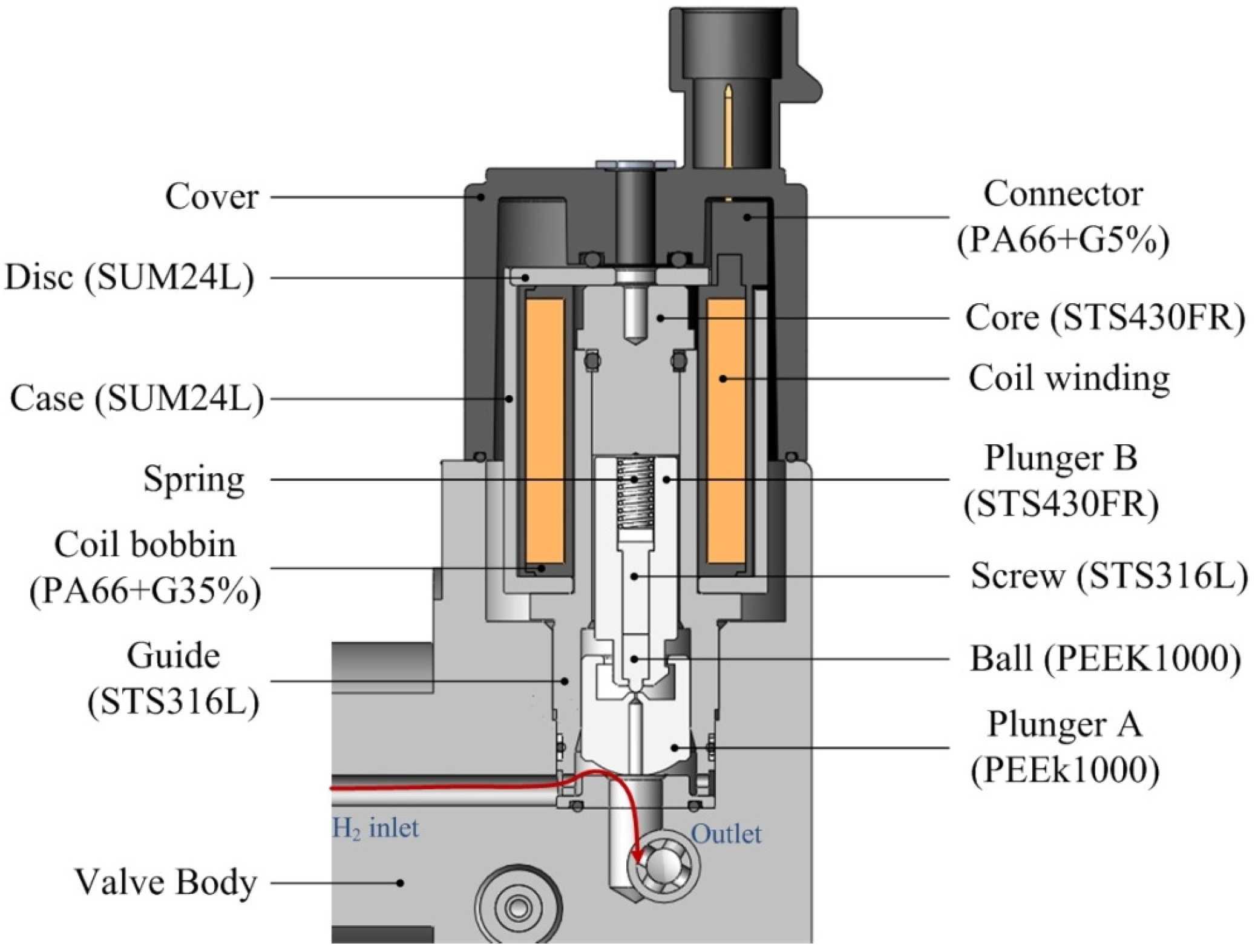
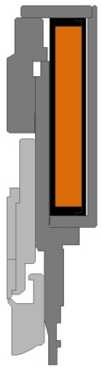
The single plunger type solenoid actuators are commonly used to open and close the flow path at low pressure. According to EU 406/2010 Annex IV, which is the first standard for hydrogen fuel cell cars presented in Europe, the maximum permissible pressure of a cylinder valve should be 875 bar, which is 1.25 times the rated pressure. In the case of ultra-high pressure of 875 bar, however, it can hardly control the flow path because the force needed to pull up the single plunger is higher than the electromagnetic force exerted by the actuator. So the double plunger type solenoid actuator which controls the flow path in two consecutive stages, even with a little bigger force than usual, is suggested shown in
Figure 1. The solenoid actuator structure consists of a coil for the formation of electromagnetic fields; a disk and a case that constitute a magnetic circuit; a core that is magnetized by the electromagnetic field generated by the coil to draw the plunger; plungers A and B, which open and close the flow path with mechanical movement; guides for the movements of the plungers; springs that restore the plungers; and O-rings to maintain of air-tightness under ultra-high pressure conditions.
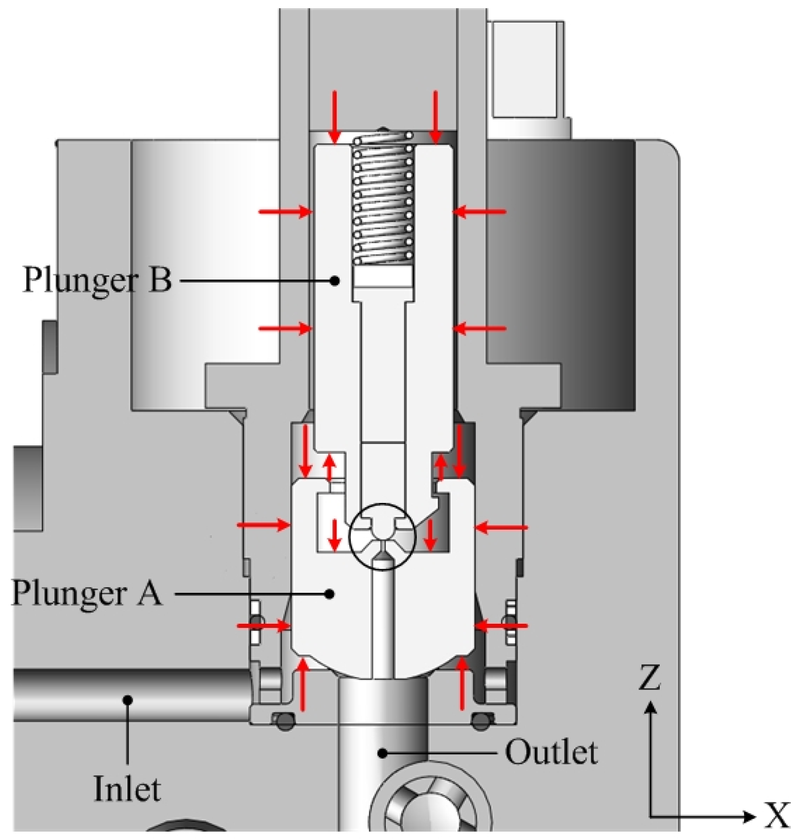
When a voltage is applied to a solenoid actuator, the core is magnetized and draws plunger B. The hydrogen in the cylinder escapes through a fine hole in plunger A. Due to the escaping hydrogen, a state of pressure equilibrium is achieved, in which the pressure in the solenoid actuator and the pressure in the flow path connecting to the fuel cell stack become the same. Plunger A is attached to plunger B and moves so that the flow path connecting to the fuel cell stack is completely opened. The attractive force of the solenoid actuator required to open the flow path should be larger than the force imposed on plunger B in the initial closed state, in which voltage is not applied to the solenoid actuator, as shown in
Figure 2. The horizontal component (X-direction) of the force applied to plunger B is offset because the shape of the plunger is symmetric across the central axis, and the vertical component (Z-direction) maintains as much of the area of the actuator in contact with plungers A and B as possible.
3. Design of Double Plunger Type Solenoid Actuator
3.1. Calculation of Required Attractive Force
The attractive force needed to open the plunger that closes the flow path should be calculated before a voltage is applied to a solenoid actuator. The force applied by the pressure of the hydrogen in the vessel to the plunger is
Ff, and the preliminary load on the spring is
Fs. The allowance rate to secure the reliability of actuator motions is
c. The attractive force
FR of the actuator that is necessary to open the flow path can be expressed as follows:
where the preload
Fs of the spring can be expressed as:
where the free length of the spring is
lf, the set length is
ls, and the spring constant is
K.
3.2. Calculation of Magnetomotive Force [11]
The magnetomotive force is the product of the number of windings
N of the coil and the current
I flowing through the coil:
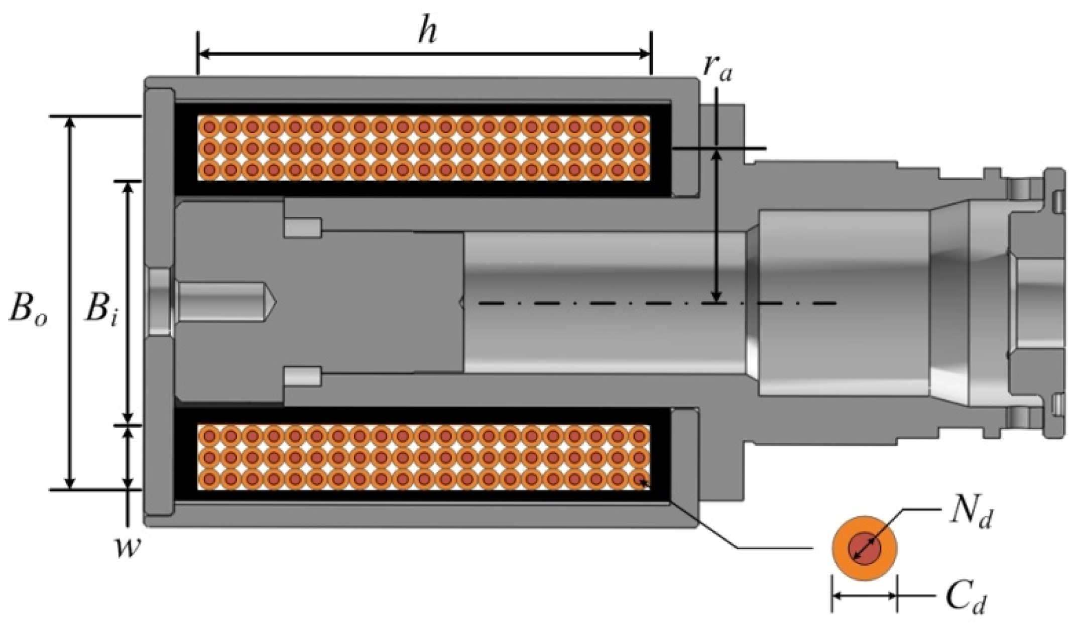
Figure 3 shows a simplified diagram of the solenoid coil bobbin and the coil wound around it. The inner diameter of the coil bobbin is
Bi, the diameter is
Bo, the height is
h, and the diameter of the enamel wire is
Cd. The number of axial laminations of the coil bobbin
nc and the number of radial laminations of the coil bobbin
mc are obtained using Equations (4) and (5), respectively. The number of coil windings
N is the product of the numbers of radial and axial laminations.
The current flowing through the coil can be expressed by Equation (7) using the specific resistance ρ, the average length of one winding lca, the number of windings N, and the root mean square (RMS) voltage VRMS according to the duty ratio of the pulse width modulation (PWM) power source.
3.3. Calculation of Temperature Increase
In general, when a current is applied to the coil, the temperature gradually increases and saturates at a constant level. Temperature increases lead to increases in coil resistance and decreases in the attractive force of the solenoid. It is important to compare the required attractive force of the solenoid with a reduction in the attractive force due to the temperature increase. The resistance value
Rs of the coil at the saturation temperature can be expressed as Equation (8) using the coil resistance
R20 at 20 °C and the saturation temperature
[
12].
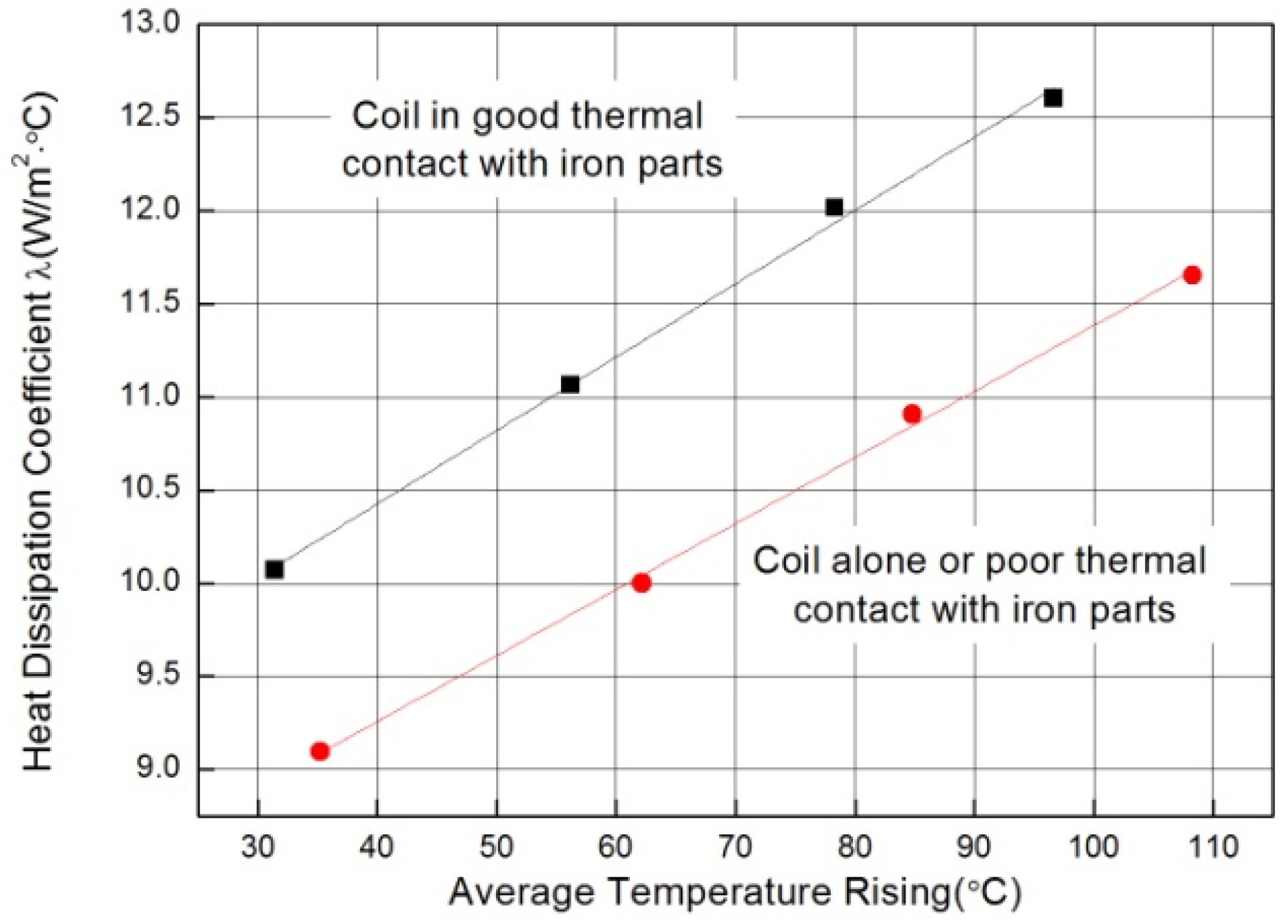
Figure 4 shows a graph of the experiment results of heat dissipation coefficients and average temperature increases according to the types of contact of the solenoid coil by Roters [
13]. Using these results, changes in the heat dissipation coefficient according to the temperature rises were obtained using Equation (9). Equation (10) provides the temperature rises in the solenoid coil using the applied voltage
VRMS, the duty ratio
Drs of the applied voltage, resistance
Rs at the saturation temperature, heat dissipation coefficient λ on the coil surface, and the surface area
Awire of the enameled wire.
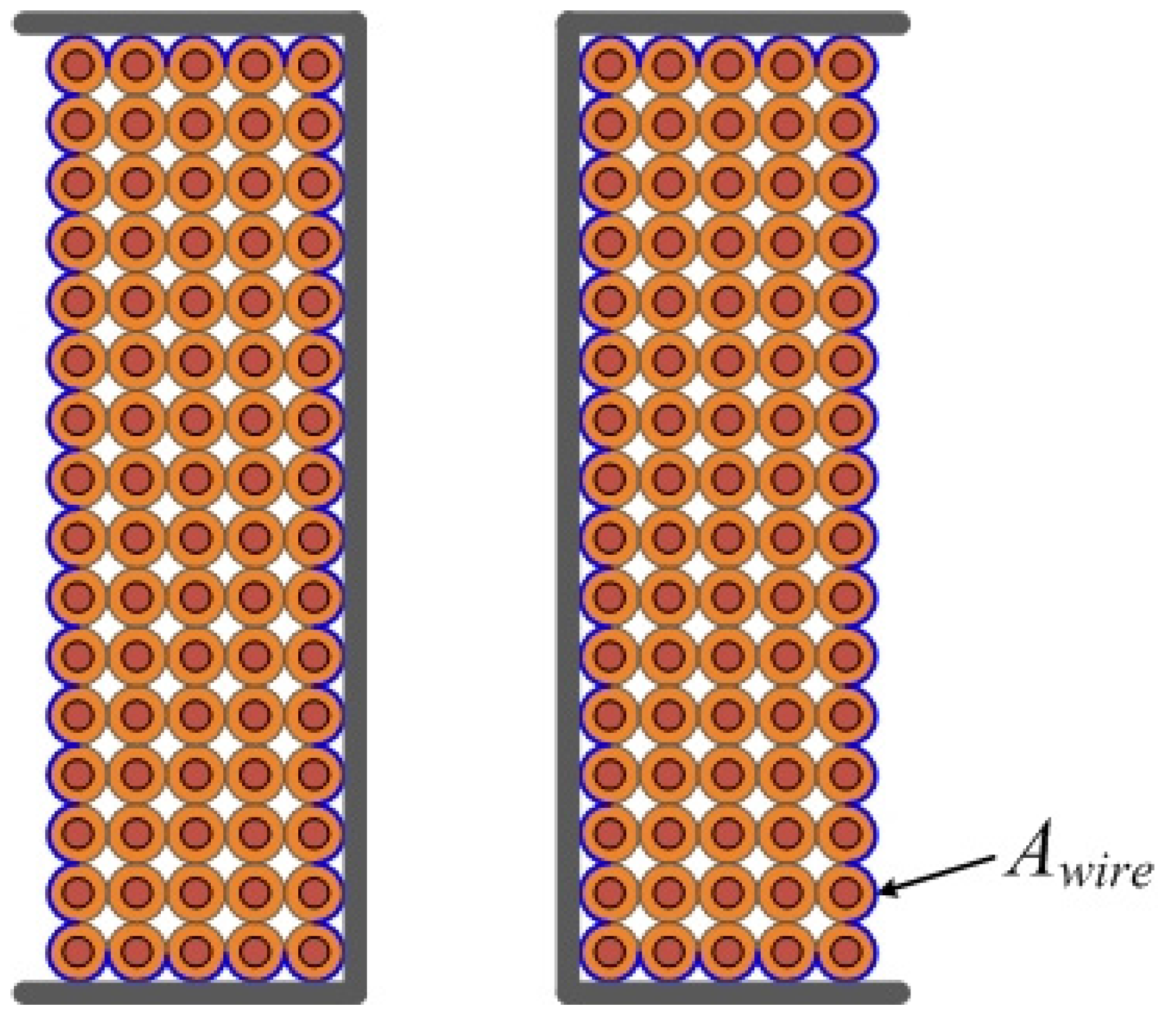
Figure 5 shows the heat dissipation area of the solenoid coil used in Equation (10), which can be expressed by Equation (11). Equation (12) shows the results of substituting Equations (8) and (9) into Equation (10) to calculate the solenoid’s temperature increase.
3.4. Calculation of Attractive Force by the Probable Flux Paths Method [14,15]
Since the ferromagnetic substance used in the solenoid actuator has much higher permeability than the surrounding space, the generated magnetic flux does not escape and instead mostly passes through the ferromagnetic substance. Therefore, the magnetic flux forms a magnetic circuit. The magnetic flux Φ generated in the solenoid can be expressed by Equation (13) using the magnetomotive force U and total magnetic resistance Rm.
The total magnetic resistance can be obtained by calculating the magnetic resistance of each component of the solenoid using the length (
li) of the magnetic path, the area (
Si) passed by the magnetic flux, and the permeability (μ) of the component material. Each of the individual magnetic resistances are then connected in series or in parallel. This method is called the probable flux paths method.
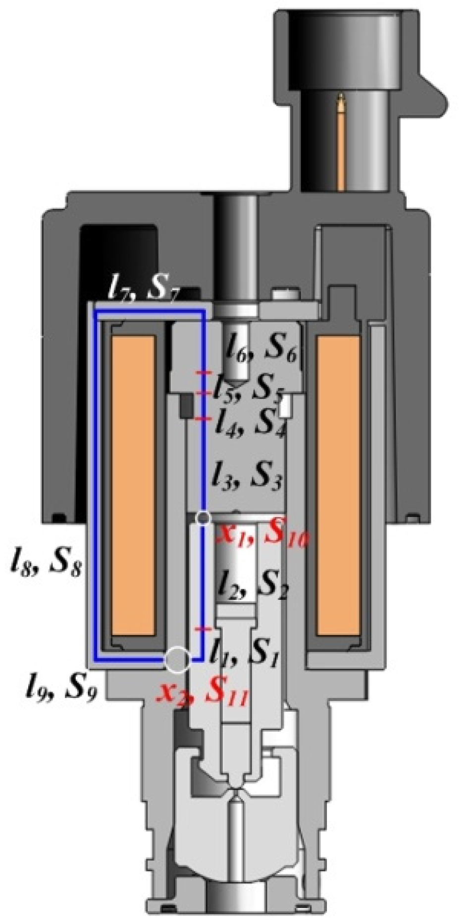
Figure 6 shows the split magnetic path used to obtain the total magnetic resistance of the solenoid. The total resistance can be obtained using Equation (14) for the individual split magnetic resistances connected in series.
The attractive force FA of the solenoid can be expressed by Equations (15) and (16) using magnetic flux density B of the magnetic pole, air permeability μ0, and cross-sectional area S10 of the magnetic pole.
3.5. Optimal Design of Solenoid Actuator
The attractive force at the saturation temperature is very important because fuel cell electric vehicles may be started again immediately after the motor has been turned off when the vehicle has stopped. Since the solenoid actuator is not sufficiently cooled in such cases, the attractive force necessary for the flow path opening must be obtainable at temperatures close to the saturation temperature.
Table 1 shows the variables and their values necessary to design solenoid actuators that can provide the attractive force required for opening the flow path at the saturation temperature. The force
Ff imposed on plunger B by the vessel pressure is 6.19 N based on the maximum permissible pressure, and the spring preload
Fs becomes 6.51 N based on Equation (2). When the allowance rate for securing reliability is set to 20%, the attractive force of the actuator necessary to open the flow path is 15.2 N according to Equation (1). The solenoid actuator coil was made using polyamide-imide enameled round copper wire (AIW), which has excellent chemical resistance and heat resistance. The diameter and the resistance per unit length of the enameled wire were selected by referring to the manufacturer’s specifications.
The slope and intercept of the heat dissipation coefficient were obtained based on the conditions in which the coil would be in good contact with the metal component. The solenoid actuator uses PWM signals to reduce power consumption, and the temperature rises after applying power with a duty ratio of 100% to the solenoid for 2 s for the initial flow path opening. Therefore, a smaller force than that for the flow path opening is required to maintain an open flow path, and the duty ratio of the force applied to the actuator is changed to 40%. The design variables were calculated using the presented design equations.
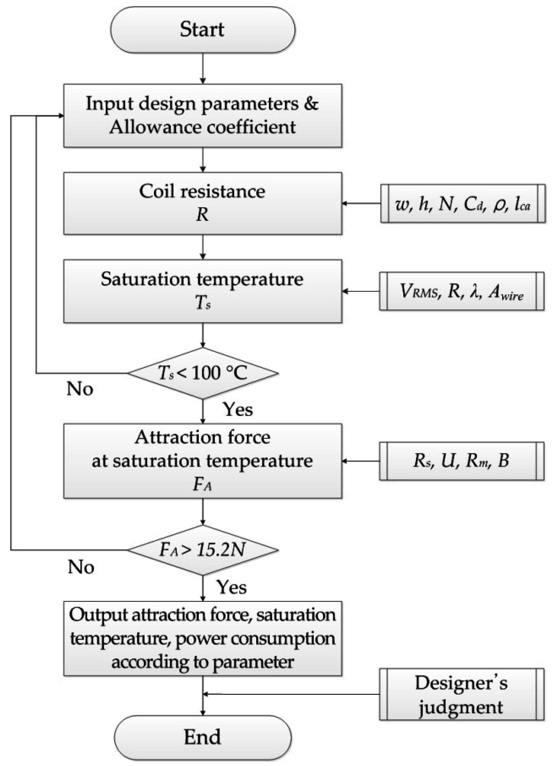
The purpose of optimal design for the solenoid actuator is to determine design parameters like coil bobbin shape and enameled wire diameter, which produce the minimize power consumption under given attraction force and saturation temperature. Once the coil resistance is determined for power consumption, number of turns in a coil and average length of one winding can be obtained by (4) through (7). The temperature rise, change resistance of a coil, magnetomotive force, magnetic flux density, and attraction force at saturation temperature are obtained by (8) through (16) sequentially, as shown in
Figure 7.
Table 2 shows the resulting values that minimize power consumption while satisfying the saturation temperature and attractive force criteria at that temperature.
4. Analysis of Solenoid Actuator
4.1. Thermal Analysis
For more accurate prediction of the saturation temperature of the solenoid actuator, steady-state heat transfer analysis was conducted using ANSYS WORKBENCH (V15, ANSYS Inc., Canonsburg, PA, USA). Internal heat generation conditions were applied to the actuator coil, and 5.53 W of power was applied at the saturation temperature. Convection conditions were applied to the plane where the actuator comes in contact with air and convection occurs due to temperature differences. The convection heat transfer coefficient was assumed to be 5 W/m
2∙°C. Heat conduction was assumed between actuator components due to contact [
16,
17].
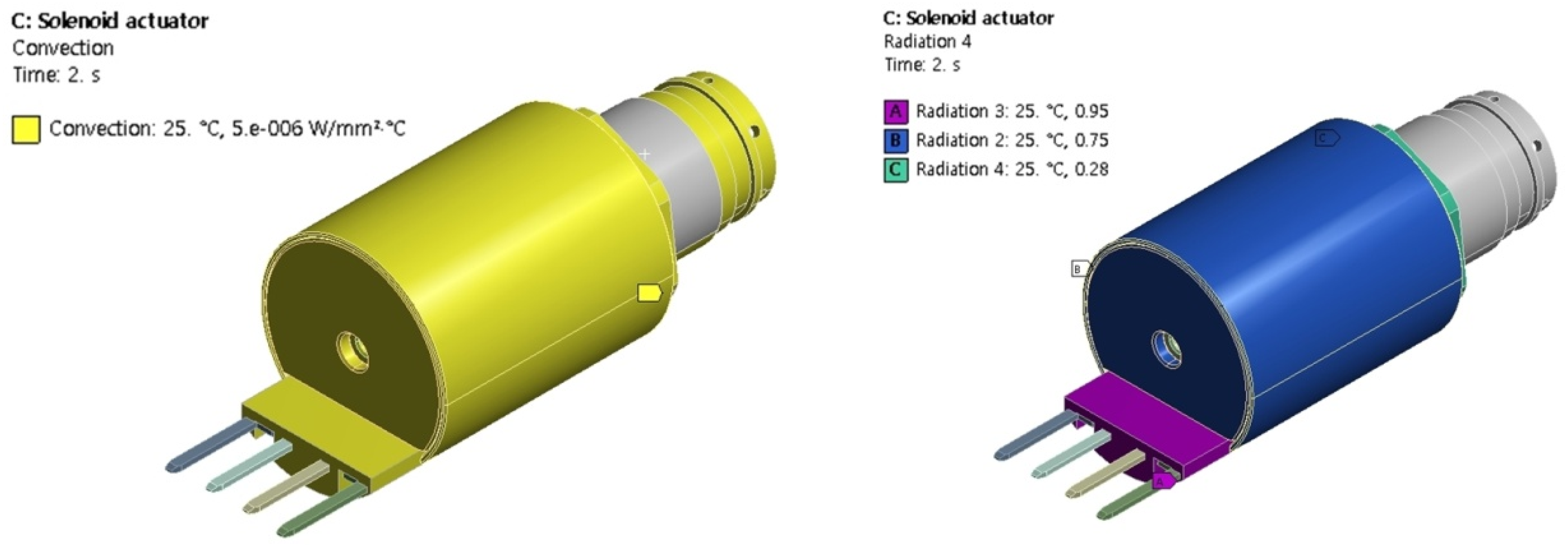
Radiation conditions were applied to the plane where convective heat transfers from the outermost surface to the atmosphere, and the air temperature was designated as 25 °C.
Figure 8 shows the convection and radiation conditions applied to the actuator.
Table 3 shows the density, specific heat capacity, and thermal conductivity coefficient of the solenoid actuator component material used in the heat transfer analysis, as well as the emissivity used in the radiation conditions. The heat transfer analysis was conducted using tetrahedron elements, and 558,984 nodes and 362,091 elements were generated.
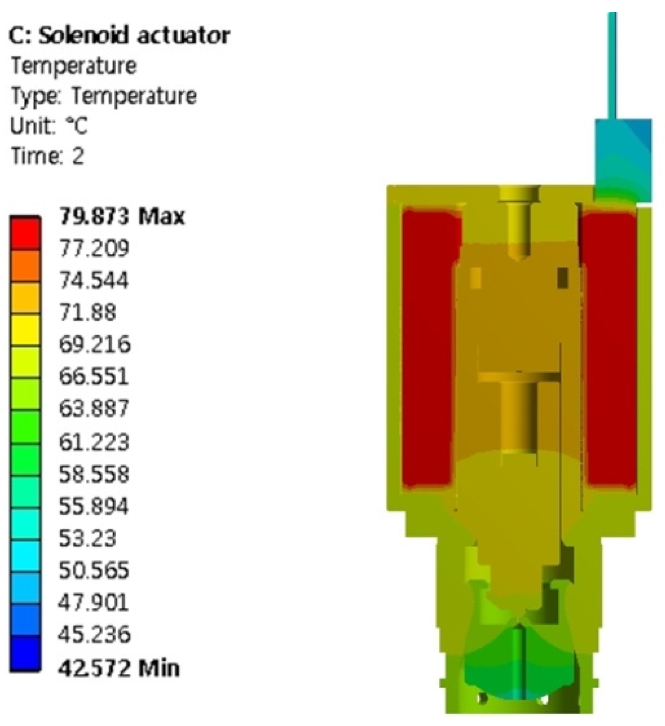
Figure 9 shows the results of the actuator heat transfer analysis. The steady-state coil temperature is 79.9 °C, which is approximately 18 °C lower than the temperature of 97.0 °C obtained using Equation (12). This difference is attributable to the fact that the heat transfer characteristics based on the shape and material of the actuator cannot be accurately reflected when obtaining the saturation temperature of the coil through Equation (12).
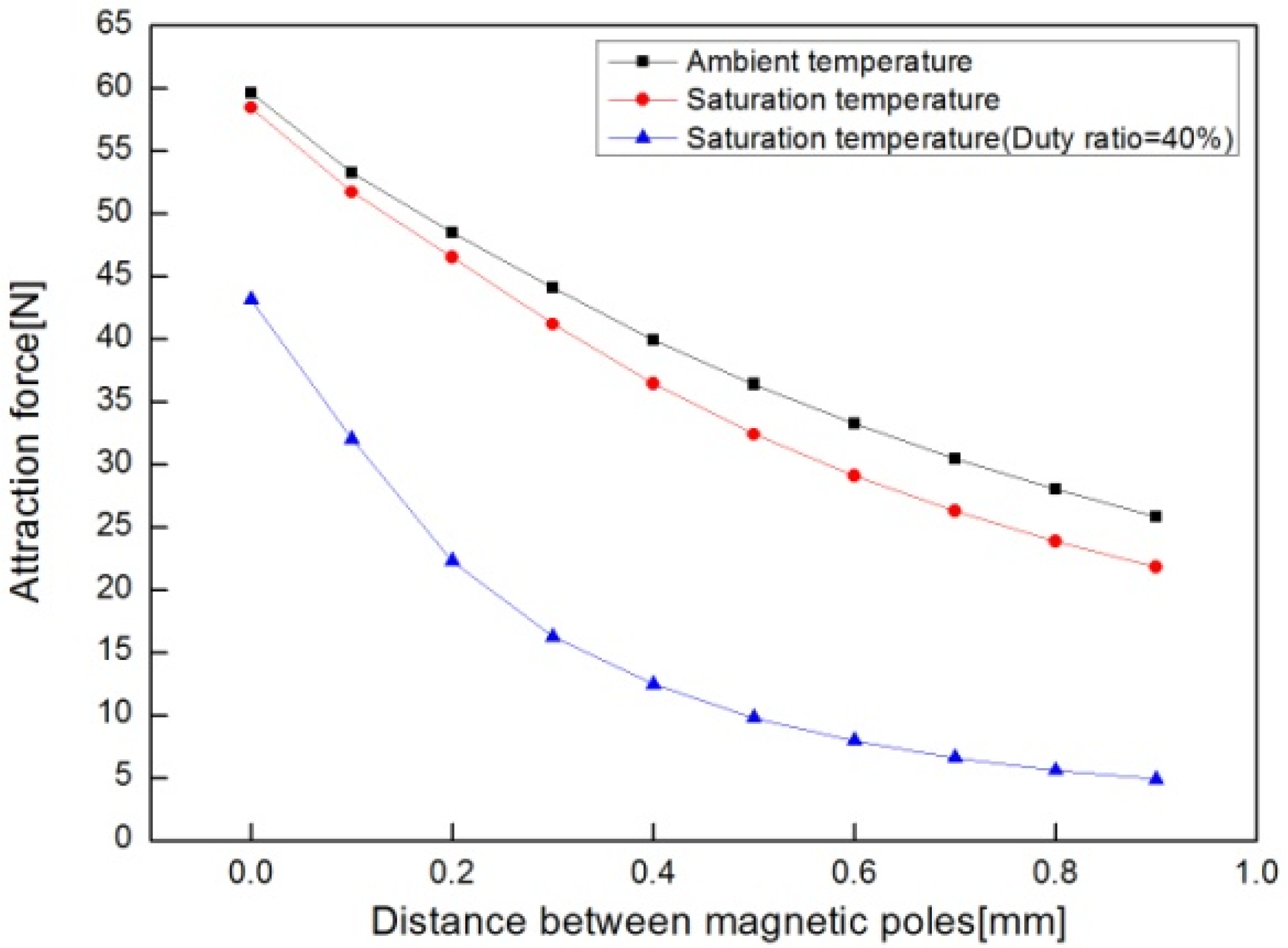
4.2. Analysis of Attractive Force
To check whether the designed actuator provides the attractive force required for opening the flow path at the saturation temperature, changes were made in the attractive force based on the distance between magnetic poles. The attractive force analysis conditions were a power duty ratio of 100% for flow path opening at ambient temperature and the saturation temperature, as well as an experimental frequency of 25 kHz and duty ratio of 40% for maintenance of the opened flow path. Electromagnetic fields were analyzed using the commercial software ANSYS Maxwell (V15, ANSYS Inc., Canonsburg, PA, USA). The simplified 2D model of the actuator for the analysis is shown in
Figure 10 [
18].
The magnetomotive force of the coil must be calculated for the analysis. The magnetomotive force of the coil was obtained using Equations (3)–(8) at ambient temperature and the saturation temperature of the coil obtained through the heat transfer analysis. The resulting magnetomotive forces at ambient temperature and the saturation temperature were 1677.02 and 1383.74 AT, respectively. For the analysis at 40% duty ratio, the inductance of the coil was calculated as 1.849 mH using Equation (17) [
19].
Table 4 shows the magnetic properties of the actuator components used in the analysis. The self-weight of the plunger and the elastic force of the spring were not considered, tetrahedron elements were used and 52,296 were generated.
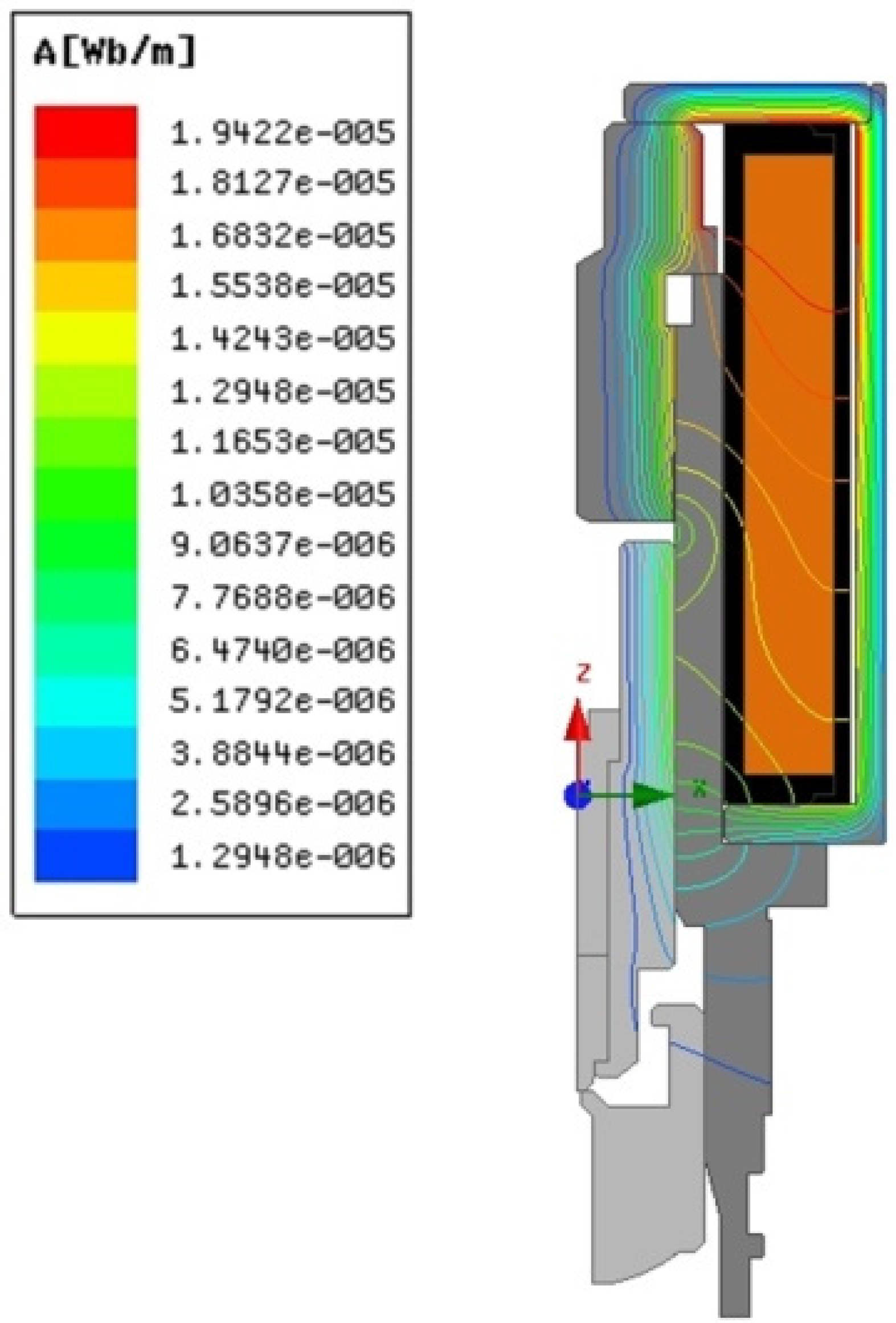
Figure 11 and
Figure 12 show the results for different distances between the magnetic poles and the distribution of magnetic flux lines. The attractive forces when the distance was 0.9 mm at ambient temperature and the saturation temperature were 25.84 and 21.81 N, respectively, which satisfy the requirement of 15.2 N for flow path opening. To maintain the opened flow path at the saturation temperature, the attractive force of the actuator should be 17.28 N due to the increased elastic force of the spring. When the core and plunger were in contact with a PWM frequency of 25 kHz and 40% duty ratio, the attractive force was 43.15 N, which satisfies the requirement.
5. Performance Test
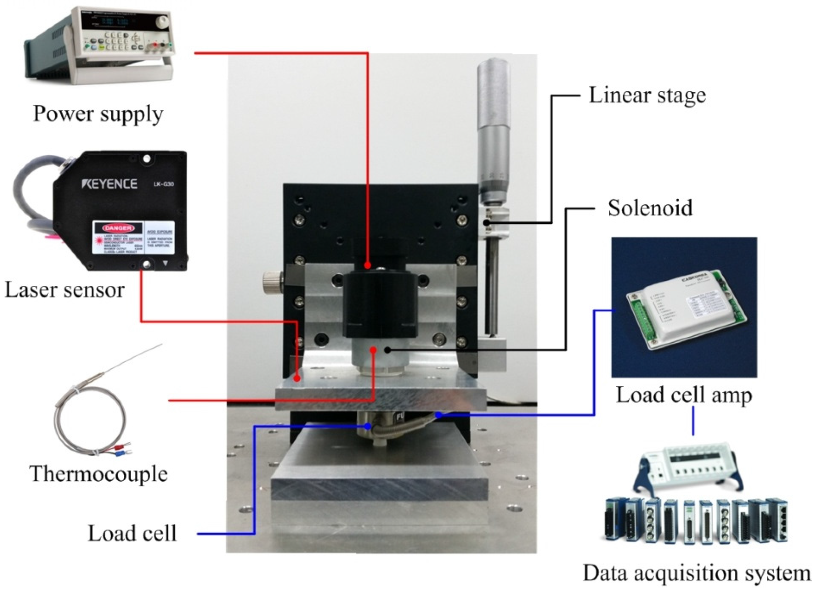
Figure 13 shows a picture of an actuator prototype and an instrument for measuring the attractive force. The instrument consists of a solenoid actuator (YOUNGDO Ind. Co., Ltd., Busan, Korea), load cell (FUTEK, Irvine, CA, USA), laser displacement sensor (Keyence, Osaka, Japan), thermocouple (OMEGA Engineering Inc., Seoul, Korea), linear stage (SCIENCETOWN, Incheon, Korea), power supply (Tektronix Inc., Beaverton, OR, USA) and data acquisition system (National Instruments, Austin, TX, USA). Before the test, the solenoid was fixed to the linear stage, which can move vertically to adjust the distances between magnetic poles [
20].
To measure the attractive force of the plunger generated by the magnetization of the core, the load cell was placed on the same central axis as the fixed solenoid, and plunger A was fastened to the load cell to measure the attractive force. Then, the linear stage was moved at intervals of 0.1 mm from the point where plunger B and the corer are in complete contact with each other. The actual shift displacement was checked using the laser displacement sensor. When the distance between magnetic poles was completely adjusted, voltage was applied to the actuator using the power supply, and the attractive force was measured from the load cell using the data collection system. To compare the results of the experiment and electromagnetic field analysis, the spring was removed to measure only the attractive force. Sufficient time was given between measurements to maintain the temperatures of the two coils at the same level, and the measured temperatures were checked using the thermocouple to ensure reliability of the data.
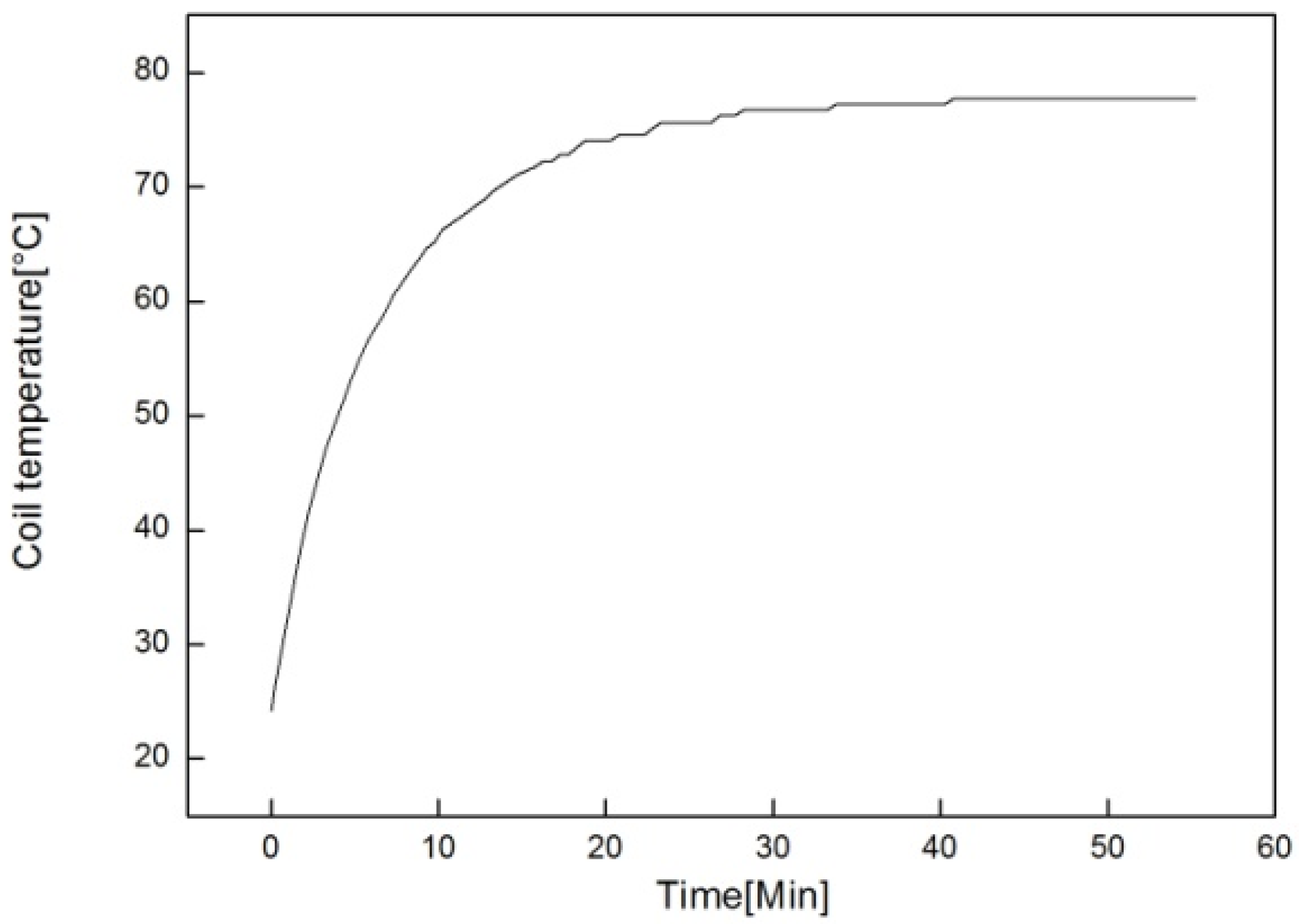
Figure 14 shows the measurements of coil temperatures at intervals of 30 s with 40% duty ratio applied. The coil temperature was saturated at approximately 77.7 °C, which was different by approximately 2.2 °C from the results of heat transfer analysis. The power consumption in the analysis was calculated for 97.0 °C (the theoretical saturation temperature), which is smaller than the power consumption obtained in experiments. The measured saturation temperature of the coil was 82.8 °C. The reason for the differences is that the assumed convection heat transfer coefficient and emissivity values are different from the actual values.
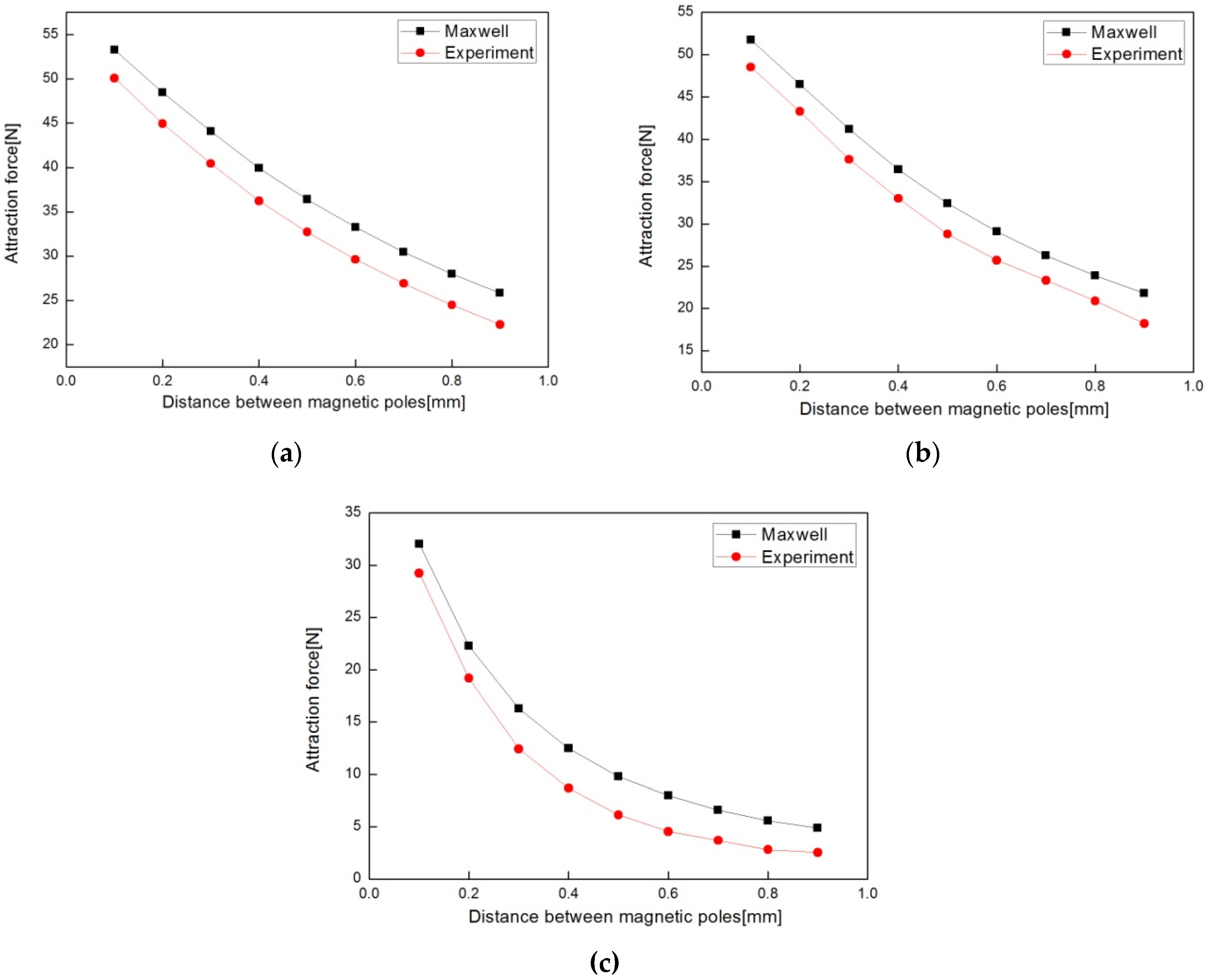
Table 5 and
Figure 15 show the measured results of attractive forces and the analysis results with respect to temperature. The force cannot be measured when the distance between magnetic poles is 0 mm, because the plunger and the core are in complete contact with each other, so this point was excluded. At 100% duty ratio and ambient temperature, the minimum, maximum, and average errors between the measured and analytical results were 3.21, 3.71, and 3.56 N respectively. At the saturation temperature, they were 2.96, 3.60, and 3.33 N, while at 40% duty ratio at the saturation temperature, they were 2.33, 3.85, and 3.17 N. These errors occurred because the 2D model was only the left part of the solenoid, so the magnetic flux leakage in the connector area could not be reflected. In addition, the self-weight of the plunger was reflected in the measured values but not the analysis.
6. Conclusions
A solenoid actuator was designed for hydrogen storage cylinder valves used in FCV, and its performance was evaluated. For the design of the solenoid actuator with reliability of the motions under ultra-high pressure, we must consider many factor such as coil resistance, temperature rise, magnetic flux density, magnetomotive force, attraction force at saturation temperature, etc. The optimal design of an actuator based on electromagnetic and heat transfer theories so that it satisfies the required attraction force at the saturation temperature was designed analytically. Heat transfer analysis was conducted to check the validity of the calculated saturation temperature, and electromagnetic field analysis was done to evaluate the attractive force at this temperature. To validate the results of the analyses, a prototype was fabricated, and the attractive force was measured.
The confirmed results are as follows:
- (1)
The structure of double plunger type solenoid actuator is introduced to obtain worked in environment of cylinder valve for FCV such as ultra-high pressure.
- (2)
In this study we derived the temperature rise formula of solenoid actuator based on heat dissipation coefficient and heat dissipation area on a coil. Formula have significant effects on the prediction for temperature increase of coil and attraction force of solenoid actuator at saturation temperature.
- (3)
The finite element analysis was used to simulate the attraction force of the solenoid actuator. The results of the comparison indicated that coil temperature and duty ratio of input voltage were crucial to the solenoid actuator attraction force. Therefore, coil temperature is one of the most important design parameters of solenoid actuators for cylinder valves.
- (4)
The optimal design and finite element analysis procedure for minimizing power consumption of PWM control solenoid actuators was proposed. The results of the finite element analysis and thermal and electromagnetic experiments indicate good matches.
Acknowledgments
This work was supported by the Human Resource Training Program for Regional Innovation and Creativity through the Ministry of Education and National Research Foundation of Korea (2013H1B8A2032233).
Author Contributions
H.R.L. designed and performed the experiments and analysis, and wrote the paper; J.H.A. and H.Y.K. built up the research project and consulted with the research process.
Conflicts of Interest
The authors declare no conflict of interest.
References
- Calvin, H.L.; Peterson, G.P. Experimental and numerical study on the cold start performance of a single PEM fuel cell. Adv. Mech. Eng. 2010, 2. [Google Scholar] [CrossRef]
- Roberto, A.F.; Fernando, B.C.; Inaki, V.M. A new approach to battery powered electric vehicles: A hydrogen fuel-cell-based range extender system. Int. J. Hydrogen Energy 2016, 41, 4808–4819. [Google Scholar]
- Han, M.G.; Chang, S.H. Evaluation of structural integrity of Type-III hydrogen pressure vessel under low-velocity car-to-car collision using finite element analysis. Compos. Struct. 2016, 148, 198–206. [Google Scholar] [CrossRef]
- Angadi, S.V.; Jackson, R.L.; Choe, S.Y.; Flowers, G.T.; Suhling, J.C.; Chang, Y.K.; Ham, J.K.; Bae, J.I. Reliability and life study of hydraulic solenoid valve. Part 2: Experimental study. Eng. Fail. Anal. 2009, 16, 944–963. [Google Scholar] [CrossRef]
- Fabbrini, A.; Garulli, A.; Mercorelli, P. A trajectory generation algorithm for optimal consumption in electromagnetic actuators. IEEE Trans. Control Syst. Technol. 2012, 20, 1025–1032. [Google Scholar] [CrossRef]
- Mercorelli, P. An adaptive and optimized switching observer for sensorless control of an electromagnetic valve actuator in camless internal combustion engines. Asian J. Control 2014, 16, 946–951. [Google Scholar] [CrossRef]
- Amirante, R.; Distaso, E.; Tamburrano, P. Sliding spool design for reducing the actuation forces in direct operated proportional directional valves: Experimental validation. Energy Convers. Manag. 2016, 119, 399–410. [Google Scholar] [CrossRef]
- Simic, M.; Herakovic, N. Reduction of the flow forces in a small hydraulic seat valve as alternative approach to improve the valve characteristics. Energy Convers. Manag. 2015, 89, 708–718. [Google Scholar] [CrossRef]
- Yu, L.; Cai, S.; Na, W. Modeling cylinder valve in hydrogen fuel cell car. In Proceedings of the 2011 Fourth International Conference on Intelligent Computation Technology and Automation, Shenzhen, China, 28–29 March 2011; pp. 845–847.
- Wang, Q.; Yang, F.; Chen, J.; Guan, H. Experimental analysis of new high-speed powerful digital solenoid valves. Energy Convers. Manag. 2011, 52, 2309–2313. [Google Scholar] [CrossRef]
- Baek, J.S.; Lee, E.W.; Lee, J.G. A design method of solenoid actuator using empirical design coefficient and optimization technique. In Proceedings of the 2007 IEEE International Electric Machines & Drives Conference, Antalya, Turkey, 2007; pp. 279–284.
- Hsu, T.S.; Poornima, K.A. Temperature prediction of the voice coil of a moving coil loudspeaker by computer simulation. Acoust. Sci. Technol. 2000, 21, 57–62. [Google Scholar] [CrossRef]
- Baek, J.S.; Lee, E.W.; Kim, H.E. Empirical design of an on and off type solenoid actuator for valve operation. KIEE Int. Trans. Electr. Mach. Energy Convers. Syst. 2004, 4, 39–46. [Google Scholar]
- Lee, J.H.; Ahn, I.S.; Park, J.O. Design and Implementation of Tactile Feedback Device using Electromagnetic Type. In Proceedings of the 1999 IEEE/RSJ International Conference on Intelligent Robots and Systems, Kyonggju, Korea, 17–21 October1999; pp. 1549–1554.
- Taghizadeh, M.; Ghaffari, A.; Najafi, F. Modeling and identification of a solenoid valve for PWM control applications. Compres Rendus Mec. 2009, 337, 131–140. [Google Scholar] [CrossRef]
- Cai, B.; Liu, Y.; Ren, C.; Abulimiti, A.; Tian, X.; Zhang, Y. Probabilistic thermal and electromagnetic analyses of subsea solenoid valves for subsea blowout preventers. J. Mech. Eng. 2012, 11, 665–672. [Google Scholar] [CrossRef]
- Angadi, S.V.; Jackson, R.L.; Choe, S.Y.; Flowers, G.T.; Suhling, J.C.; Chang, Y.K.; Ham, J.K. Reliability and life study of hydraulic solenoid valve. Part 1: A multi-physics finite element model. Eng. Fail. Anal. 2009, 16, 874–887. [Google Scholar] [CrossRef]
- Cheng, Q.; Zhang, Z.; Xie, N. Power losses and dynamic response analysis of ultra-high speed solenoid injector within different driven strategies. Appl. Therm. Eng. 2015, 91, 611–621. [Google Scholar] [CrossRef]
- Wheeler, H.A. Simple inductance formulas for radio coils. Proc. Inst. Radio Eng. 1928, 16, 1398–1400. [Google Scholar] [CrossRef]
- Chaides, O.; Garza, H.A. Design and characterization of a linear micropositioner based on solenoid and compliant mechanism. Mechatronics 2011, 21, 1252–1258. [Google Scholar] [CrossRef]
© 2016 by the authors; licensee MDPI, Basel, Switzerland. This article is an open access article distributed under the terms and conditions of the Creative Commons Attribution (CC-BY) license (http://creativecommons.org/licenses/by/4.0/).


