
Design of the Secondary Optical Elements for Concentrated Photovoltaic Units with Fresnel Lenses

Abstract
:1. Introduction
2. Preliminary Design of SOEs

| Size of Fresnel Lens | 40 mm × 40 mm |
|---|---|
| Thickness of Fresnel lens | 2 mm |
| Material | Silicone-on-Glass (BK7) |
| Light source | divergence angle of 0.265 degrees |
| Radian flux | 1.36 W |
| Wavelength | 550 nm |
| Index of Refraction of BK7 | 1.518 |
| Index of Refraction of Urethane | 1.510 |
| Size of solar cell | 1.25 mm × 1.25 mm |
| Geometrical concentration ratio | 1024 |
| Focal length | 130.1 mm |
| Prism pitch of Fresnel lens | 0.2 mm |
2.1. KOD-Type SOE


2.2. KFTS-Type SOE


2.3. SP-Type SOE


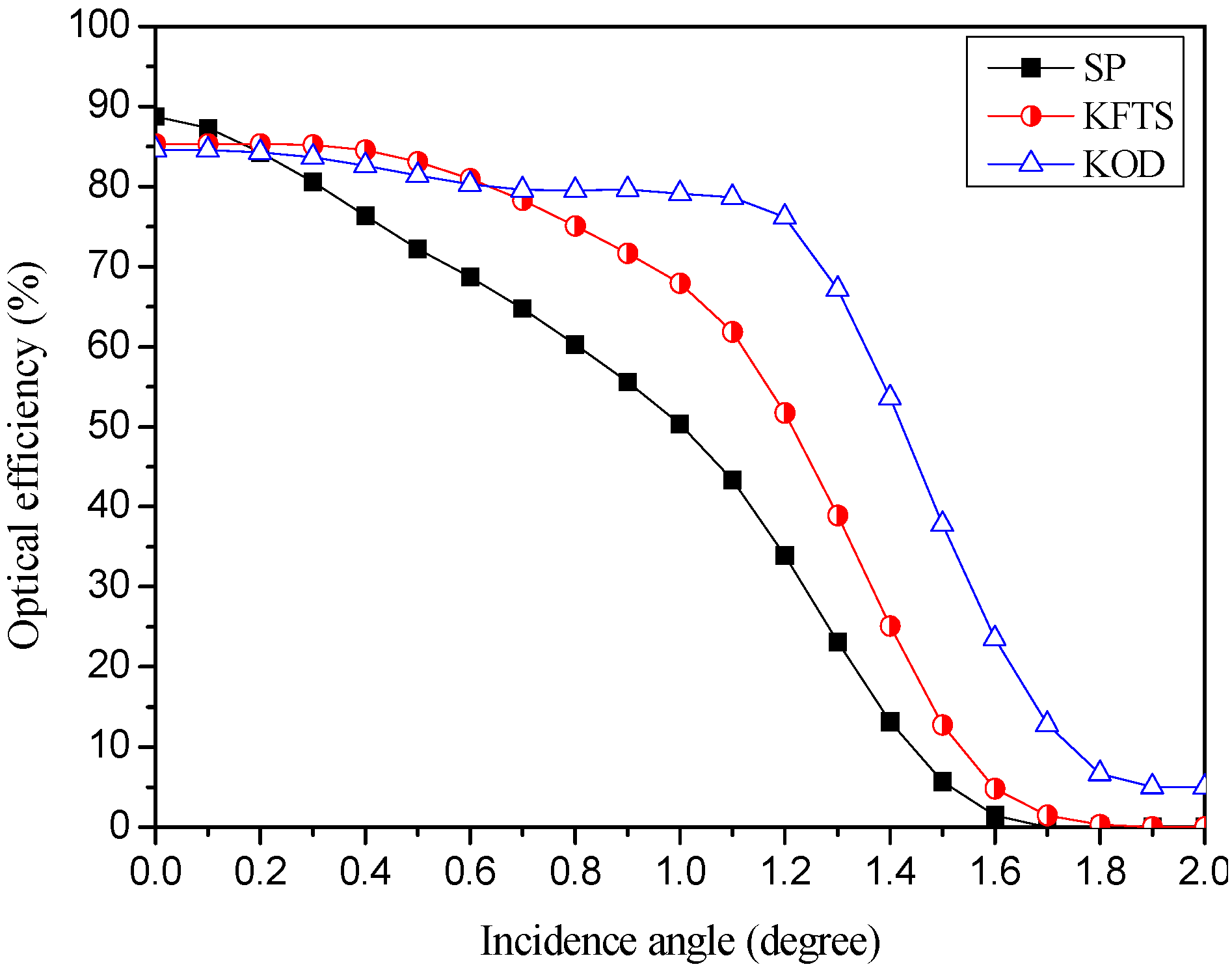
2.4. Comparison of Three Types of SOE
| SOE | No SOE | KOD | KFTS | SP |
|---|---|---|---|---|
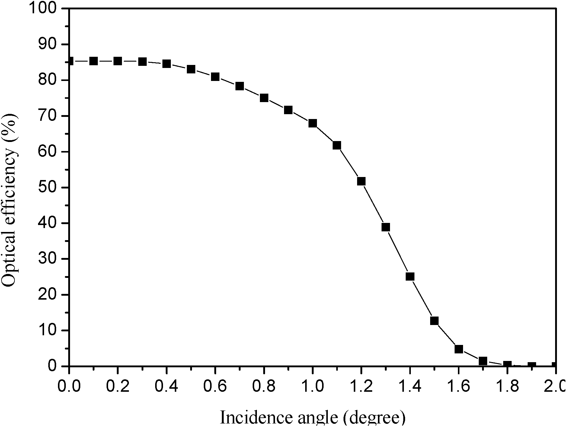
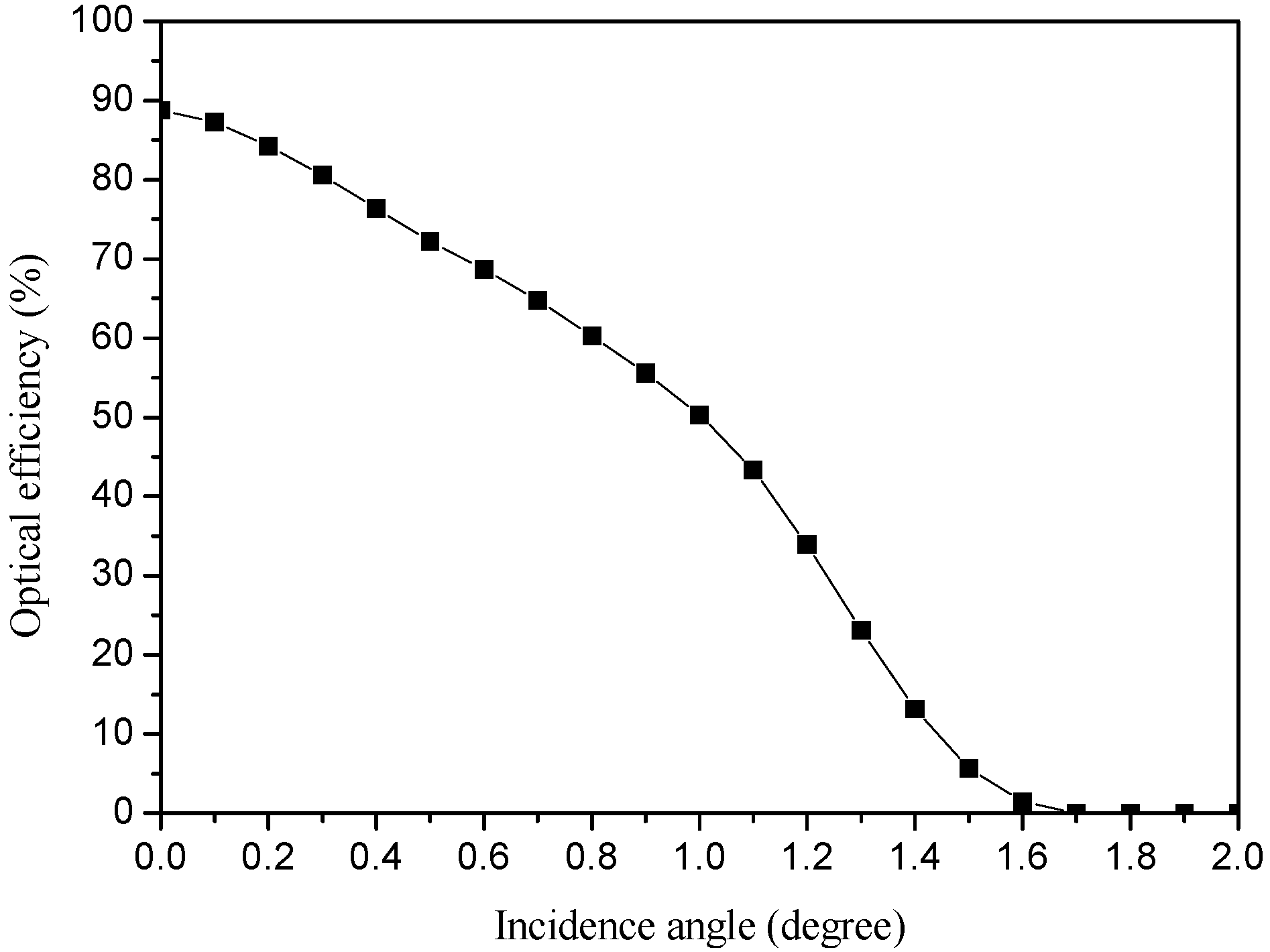
| Acceptance angle (degree) | 0.1 | 1.2 | 0.7 | 0.3 |
| Optical efficiency under normal incidence (%) | 85 | 84.6 | 85.3 | 88.7 |
| Optical efficiency at the acceptance angle (%) | 75.8 | 76.2 | 78.3 | 80.5 |
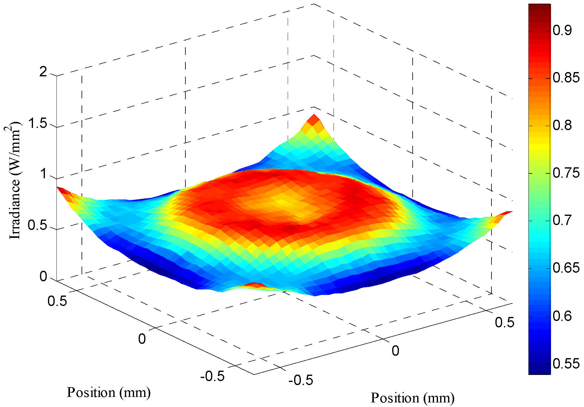
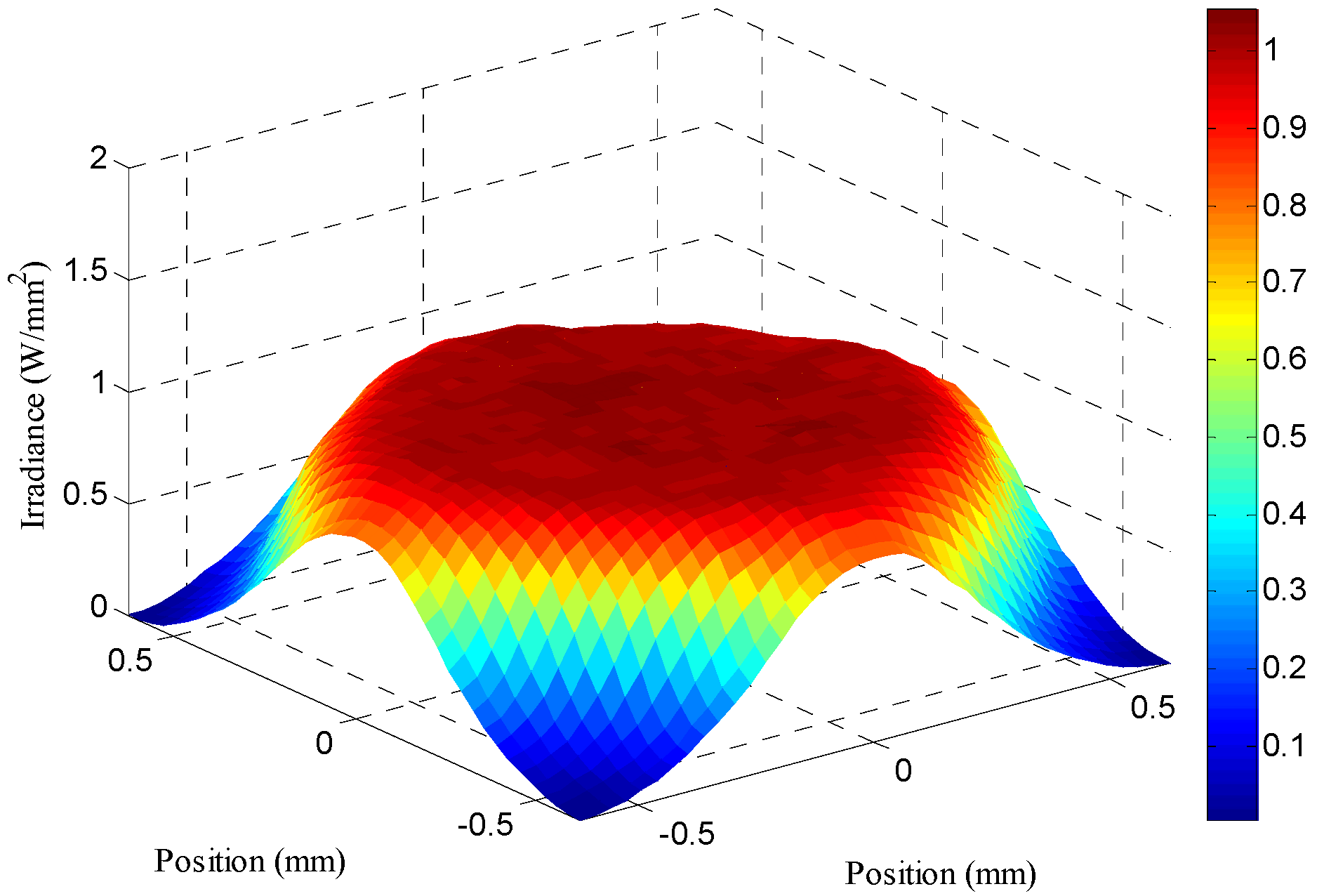
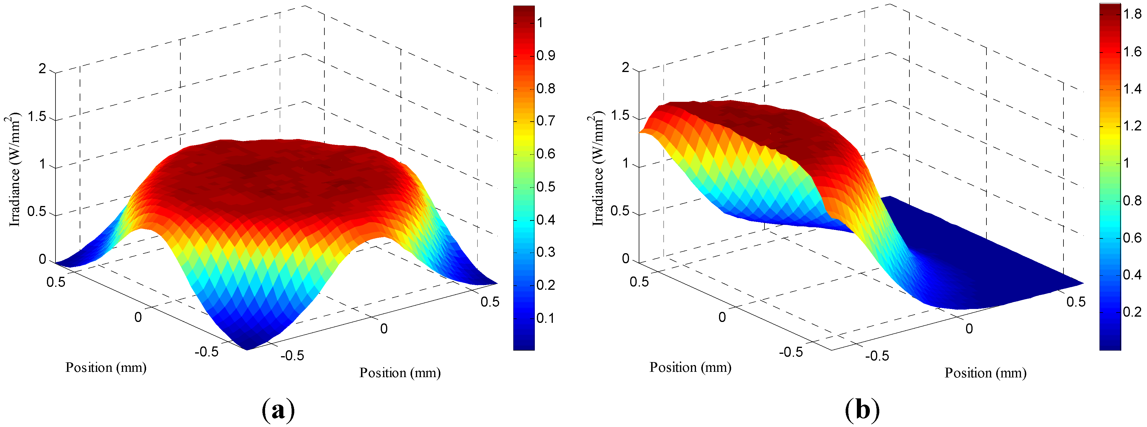
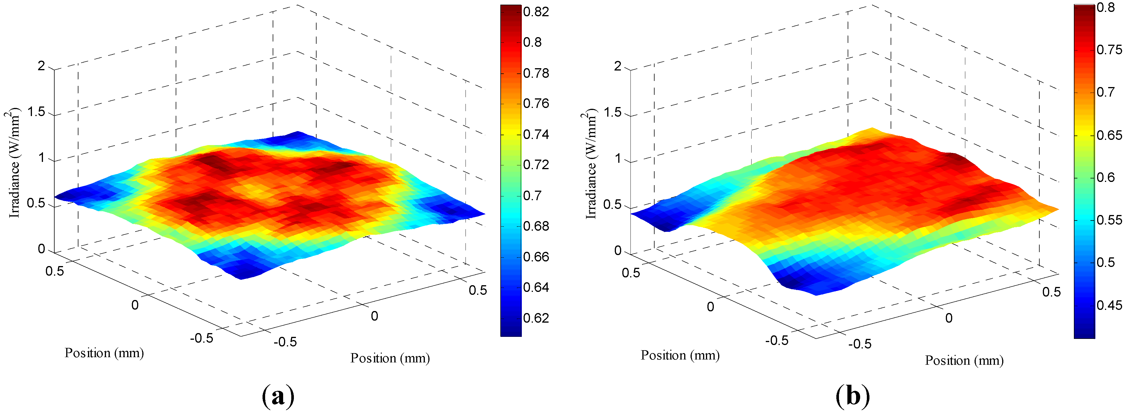
| Peak value of irradiance on the receiver under normal incidence (W/mm2) | 1.0557 | 0.9291 | 0.7916 | 1.0555 |
3. Optimum Design of SOE
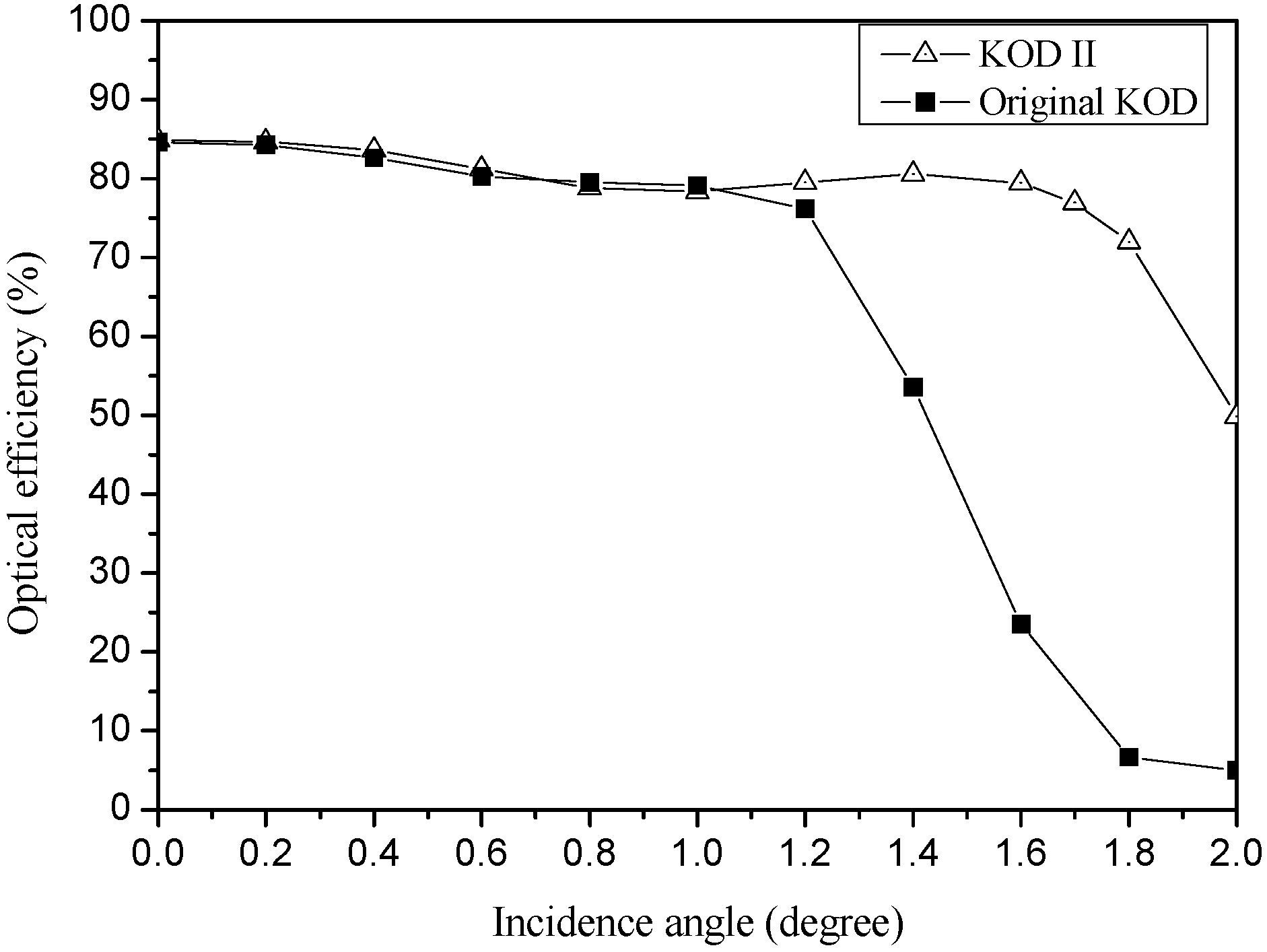
3.1. KOD II-Type SOE
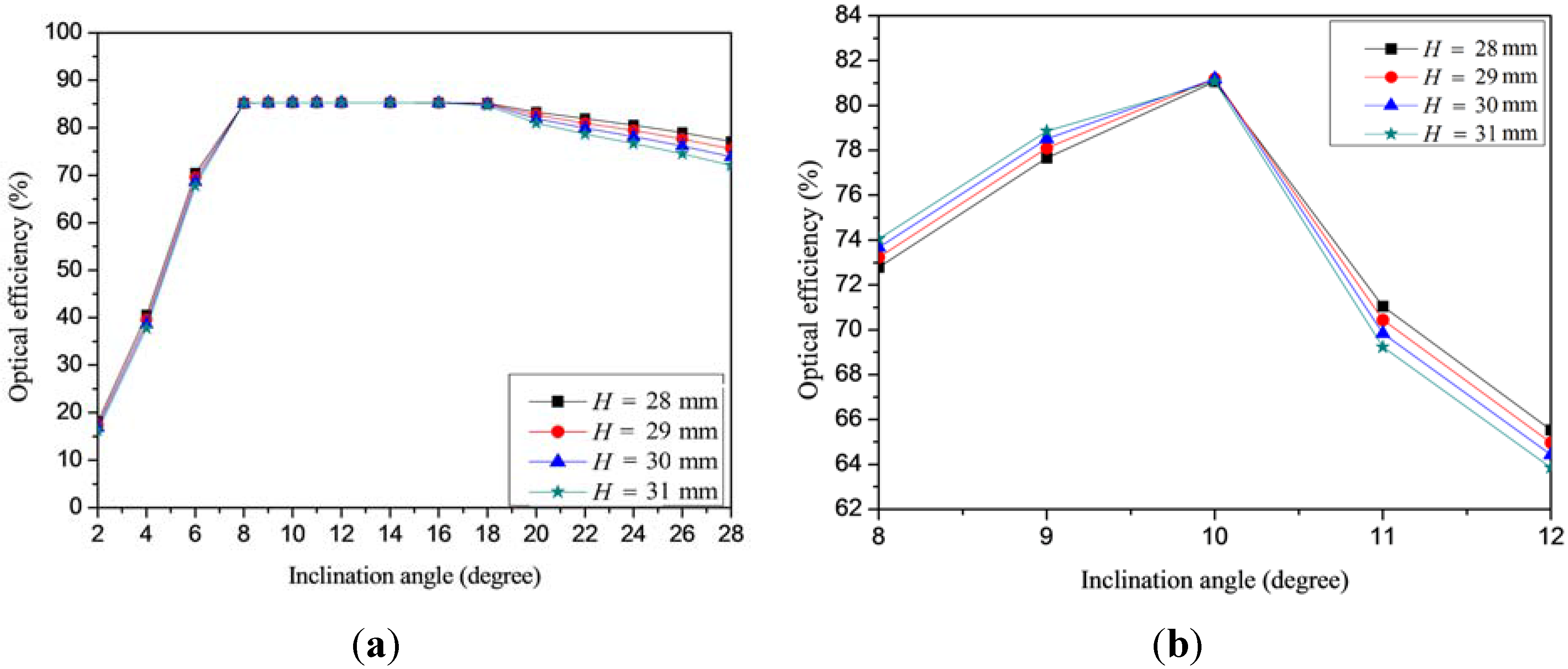
- (1)
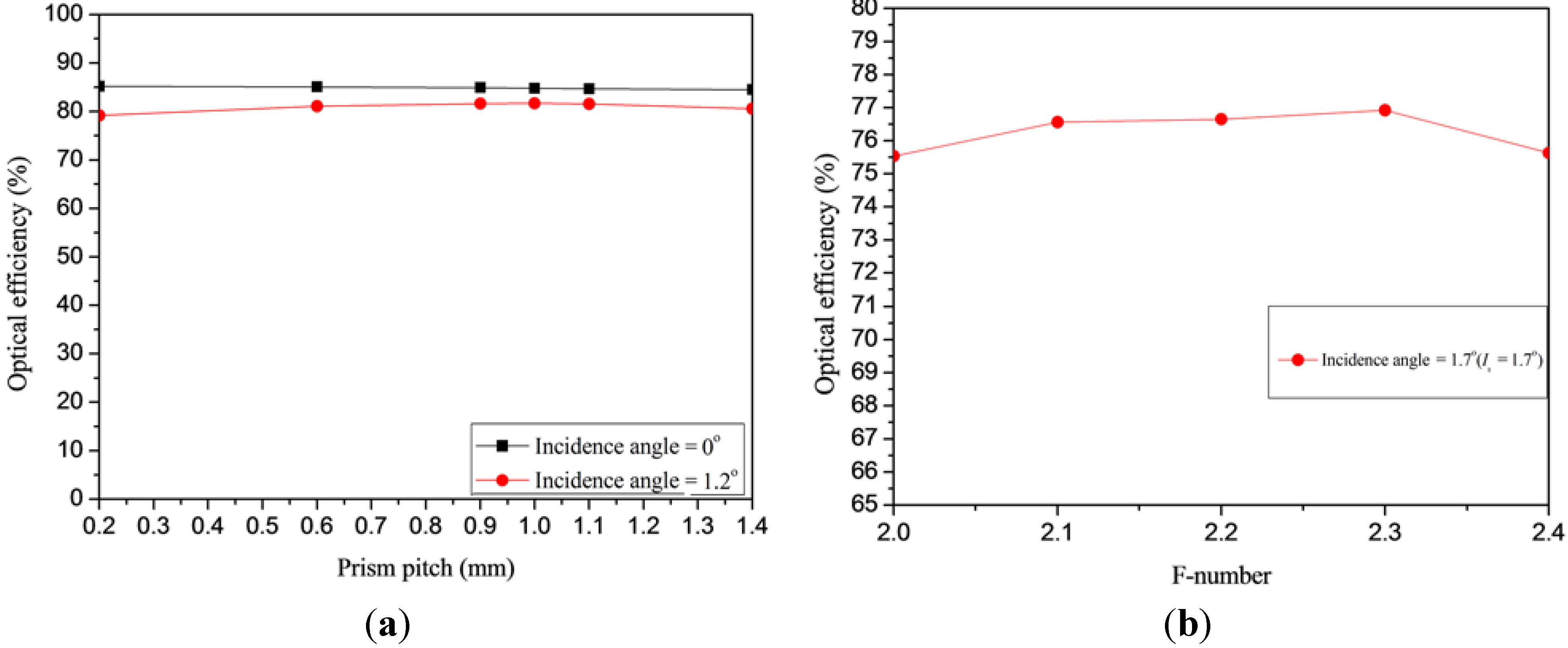
- The original prism pitch of the Fresnel lens with the KOD-type SOE was 0.2 mm. The resulting optical efficiencies under various prism pitch, ranging from 0.2 mm to 1.4 mm, were calculated and compared, as shown in Figure 12a. Figure 12a shows that when the prism pitch was 1.0 mm, the optical efficiencies under normal incidence and at an incidence deviation of 1.2° were both the highest. Hence, the prism pitch was selected as 1 mm.
- (2)
- As Figure 12b shows, the effects of the F-number (ranging from F/2.0 to F/2.4) of the Fresnel lens and the designed incidence angle Ii of the KOD-type SOE were calculated and compared. The elliptical curve of the top section of the KOD-type SOE was re-calculated according to different values of the designed incidence angle Ii. Theoretically, the designed incidence angle of the KOD-type SOE Ii is very similar to the calculated acceptance angle. It was found that the best optical efficiency at an incidence angle of 1.7° with an F-number of 2.3. Notably, the F/2.3 was the original value of the F-number, which means the focal length of the POE was unchanged.
- (3)
- The optimum design of KOD is designated as KOD II in this study.

| SOE | KOD | KOD II |
|---|---|---|
| Acceptance angle (degree) | 1.2 | 1.7 |
| Optical efficiency under normal incidence (%) | 84.6 | 85 |
| Optical efficiency at the acceptance angle (%) | 76.2 | 76.9 |


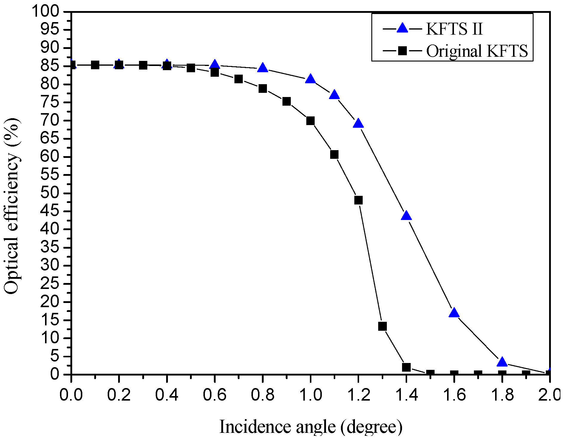
3.2. KFTS II-Type SOE

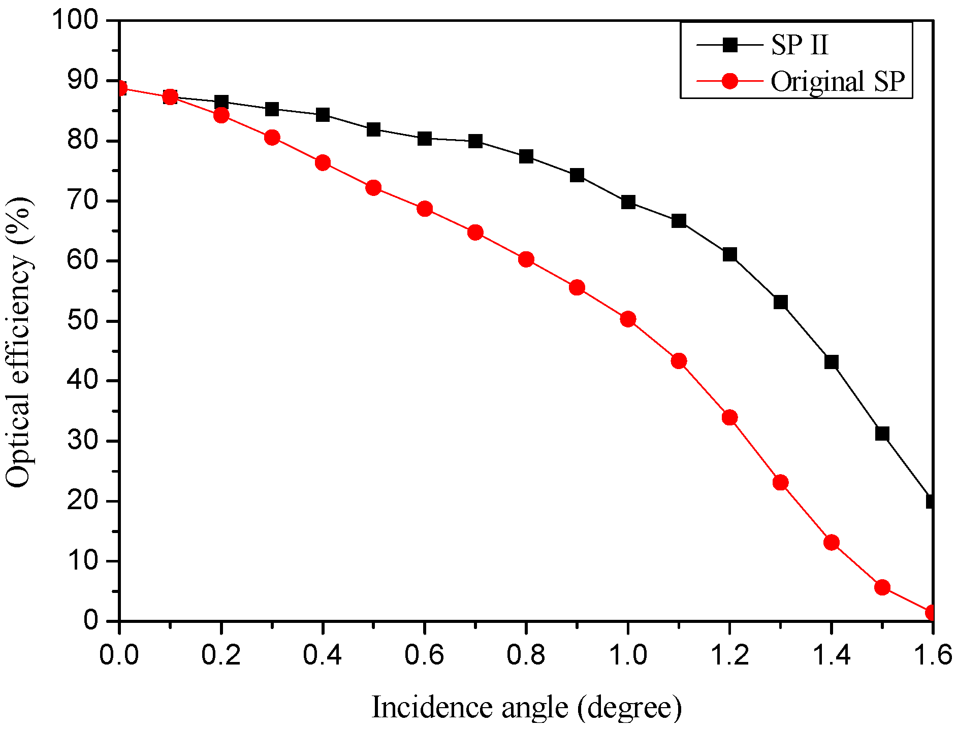
3.3. SP II-Type SOE


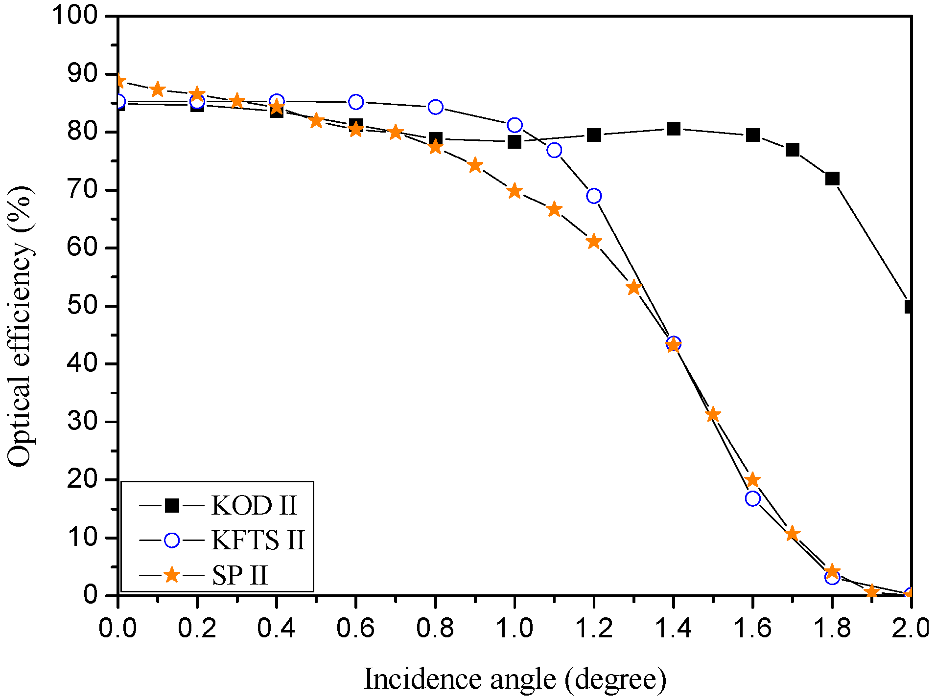
3.4. Comparison of Three Optimum SOEs

| SOE | KOD II | KFTS II | SP II |
|---|---|---|---|
| Acceptance angle (degree) | 1.7 | 1.1 | 0.7 |
| Optical efficiency under normal incidence (%) | 85.0 | 85.0 | 88.7 |
| Optical efficiency at the acceptance angle (%) | 76.9 | 76.9 | 79.9 |
| Peak value of irradiance on the receiver under normal incidence (W/mm2) | 1.1374 | 0.8249 | 1.0555 |
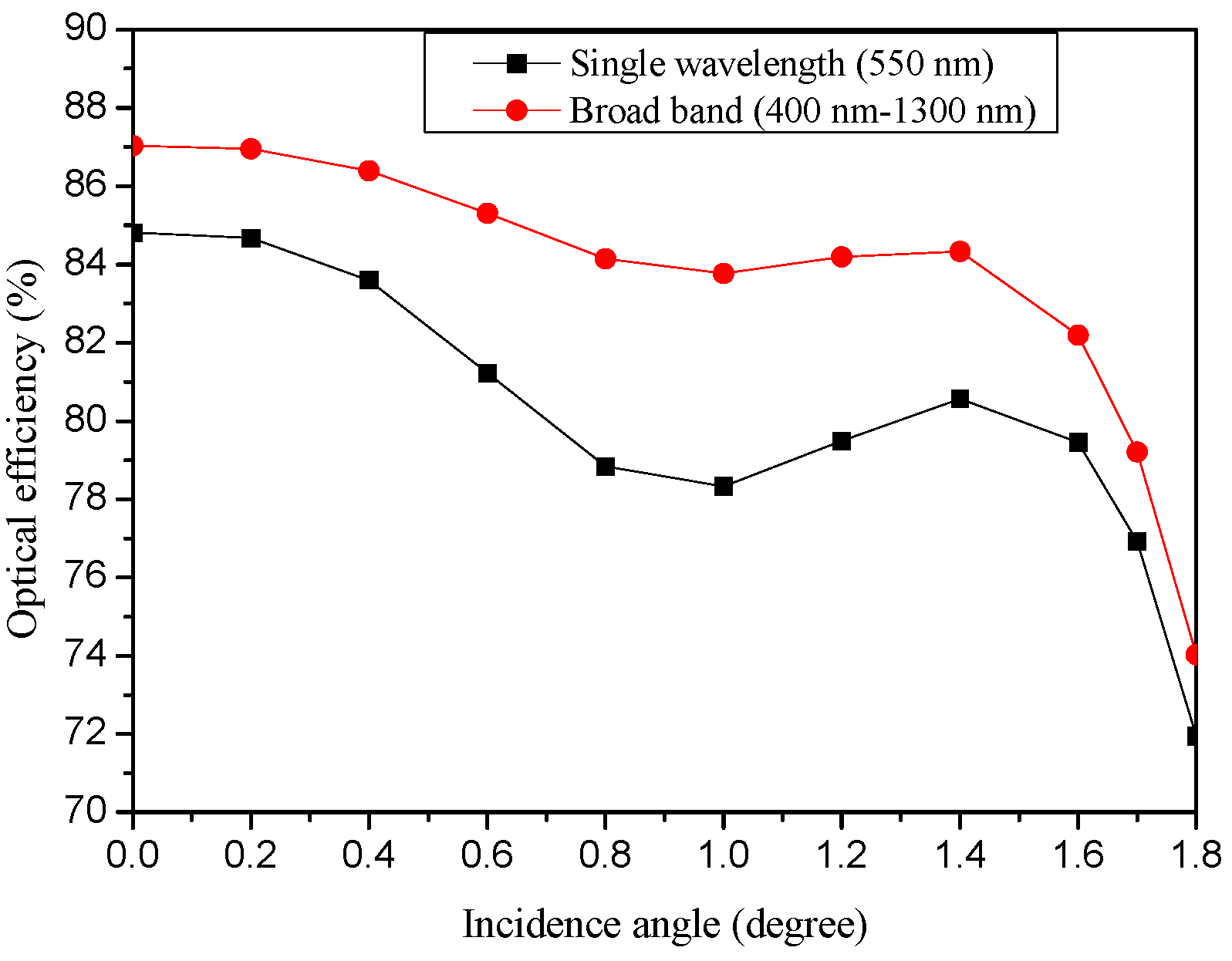
3.5. Broadband Solar Spectrum Simulation with KOD II—SOE
| Wavelength (nm) | Radiant Flux on POE (W) | Percentage (%) |
|---|---|---|
| 400–500 | 0.19 | 15.46 |
| 501–600 | 0.21 | 17.79 |
| 601–700 | 0.2 | 16.74 |
| 701–800 | 0.17 | 13.95 |
| 801–900 | 0.14 | 11.65 |
| 901–1000 | 0.08 | 7.04 |
| 1001–1100 | 0.1 | 8.1 |
| 1101–1200 | 0.05 | 4 |
| 1201–1300 | 0.07 | 5.47 |
| Sum | 1.2 | 100 |

| Optical Performance | Broadband (400 nm–1300 nm) | Single Wavelength (550 nm) |
|---|---|---|
| Acceptance angle (degree) | 1.7 | 1.7 |
| Optical efficiency under normal incidence (%) | 87 | 85 |
| Optical efficiency at the acceptance angle (%) | 79.2 | 76.9 |
| Peak value of irradiance on the receiver under normal incidence (W/mm2) | 0.9236 | 1.1374 |

4. Conclusions
Acknowledgments
Author Contributions
Conflicts of Interest
References
- Luque, A.; Andreev, V. Concentrator Photovoltaic, 1st ed.; Springer Verlag: Berlin, Germany, 2007. [Google Scholar]
- Winston, R.; Minano, J.C.; Benitez, P.G.; Shatz, N.; Bortz, J.C. Nonimaging Optics, 1st ed.; Elsevier-Academic Press: New York, NY, USA, 2005. [Google Scholar]
- Baños, R.; Manzano-Agugliaro, F.; Montoya, F.G.; Gil, C.; Alcayde, A.; Gómez, J. Optimization methods applied to renewable and sustainable energy: A review. Renew. Sustain. Energy Rev. 2011, 15, 1753–1766. [Google Scholar] [CrossRef]
- Rumyantsev, V.D. Solar concentrator modules with silicone-on-glass Fresnel lens panels and multijunction cells. Optics Express 2010, 18, A17–A24. [Google Scholar] [CrossRef] [PubMed]
- Duerr, F.; Meuret, Y.; Thienpont, H. Miniaturization of Fresnel lenses for solar concentration: A quantitative investigation. Appl. Optics 2010, 49, 2339–2346. [Google Scholar] [CrossRef] [PubMed]
- Ryu, K.; Rhee, J.-G.; Park, K.-M.; Kim, J. Concept and design of modular Fresnel lenses for concentration solar PV system. Sol. Energy 2006, 80, 1580–1587. [Google Scholar] [CrossRef]
- Huang, J.-H.; Fei, W.-C.; Hsu, W.-C.; Tsai, J.-C. Solar concentrator constructed with a circular prism array. Appl. Optics 2010, 49, 4472–4478. [Google Scholar] [CrossRef] [PubMed]
- Andreev, V.M.; Grilikhes, V.A.; Soluyanov, A.A.; Vlasova, E.V.; Shvarts, M.Z. Optimization of the secondary optics for photovoltaic units with Fresnel lenses. In Proceedings of the 23th European Photovoltaic Solar Energy Conference, Valencia, Spain, 1–5 September 2008; pp. 126–131.
- Victoria, M.; Doḿinguez, C.; Ant́on, I.; Sala, G. Comparative analysis of different secondary optical elements for aspheric primary lenses. Optics Express 2009, 17, 6487–6492. [Google Scholar] [CrossRef] [PubMed]
- Fu, L.; Leutz, R.; Annen, H.P. Secondary optics for Fresnel lens solar concentrators. In Nonimaging Optics: Efficient Design for Illumination and Solar Concentration VII. Proceedings of SPIE 7785, San Diego, CA, USA, 1 August 2010; pp. 778509.1–778509.6.
- Zhuang, Z.; Yu, F. Optimization design of hybrid Fresnel-based concentrator for generating uniformity irradiance with the broad solar spectrum. Optics Laser Technol. 2014, 60, 27–33. [Google Scholar] [CrossRef]
- Buljan, M.; Miñano, J.C.; Benítez, P.; Mohedano, R.; Chaves, J. Improving performances of Fresnel CPV systems: Fresnel-RXI Köhler concentrator. Optics Express 2014, 22, A205–A210. [Google Scholar] [CrossRef] [PubMed]
- Lv, H.; Sheng, F.; Dai, J.; Liu, W.; Cheng, C.; Zhang, J. Temperature-dependent model of concentrator photovoltaic modules combining optical elements and III-V multi-junction solar cells. Sol. Energy 2015, 112, 351–360. [Google Scholar] [CrossRef]
- Shvarts, M.Z.; Andreev, V.M.; Gorohov, V.S.; Grilikhes, V.A.; Petrenko, A.E.; Soluyanov, A.A.; Timoshina, N.H. Flat-plate Fresnel lenses with improved concentrating capabilities: Designing, manufacturing and test. In Proceedings of the 33th Photovoltaic Specialists Conference, San Diego, CA, USA, 11–16 May 2008; pp. 1–6.
- Chaves, J. Introduction to Nonimaging Optics, 1st ed.; CRC Press: Boca Raton, FL, USA, 2008. [Google Scholar]
© 2015 by the authors; licensee MDPI, Basel, Switzerland. This article is an open access article distributed under the terms and conditions of the Creative Commons Attribution license (http://creativecommons.org/licenses/by/4.0/).
Share and Cite
Chen, Y.-C.; Chiang, H.-W. Design of the Secondary Optical Elements for Concentrated Photovoltaic Units with Fresnel Lenses. Appl. Sci. 2015, 5, 770-786. https://doi.org/10.3390/app5040770
Chen Y-C, Chiang H-W. Design of the Secondary Optical Elements for Concentrated Photovoltaic Units with Fresnel Lenses. Applied Sciences. 2015; 5(4):770-786. https://doi.org/10.3390/app5040770
Chicago/Turabian StyleChen, Yi-Cheng, and Hung-Wei Chiang. 2015. "Design of the Secondary Optical Elements for Concentrated Photovoltaic Units with Fresnel Lenses" Applied Sciences 5, no. 4: 770-786. https://doi.org/10.3390/app5040770
APA StyleChen, Y.-C., & Chiang, H.-W. (2015). Design of the Secondary Optical Elements for Concentrated Photovoltaic Units with Fresnel Lenses. Applied Sciences, 5(4), 770-786. https://doi.org/10.3390/app5040770