
Polypropylene/Graphene and Polypropylene/Carbon Fiber Conductive Composites: Mechanical, Crystallization and Electromagnetic Properties

 ,
, 

Abstract
:1. Introduction
2. Experimental Section
2.1. Materials

2.2. Methods
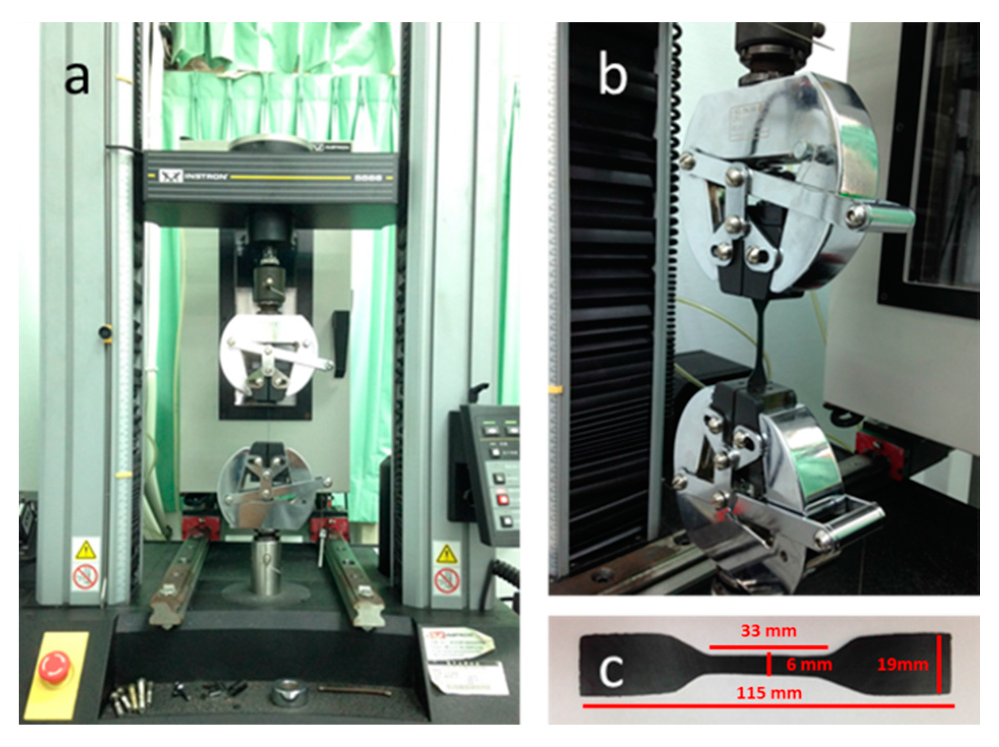
2.3. Tests
3. Results and Discussion
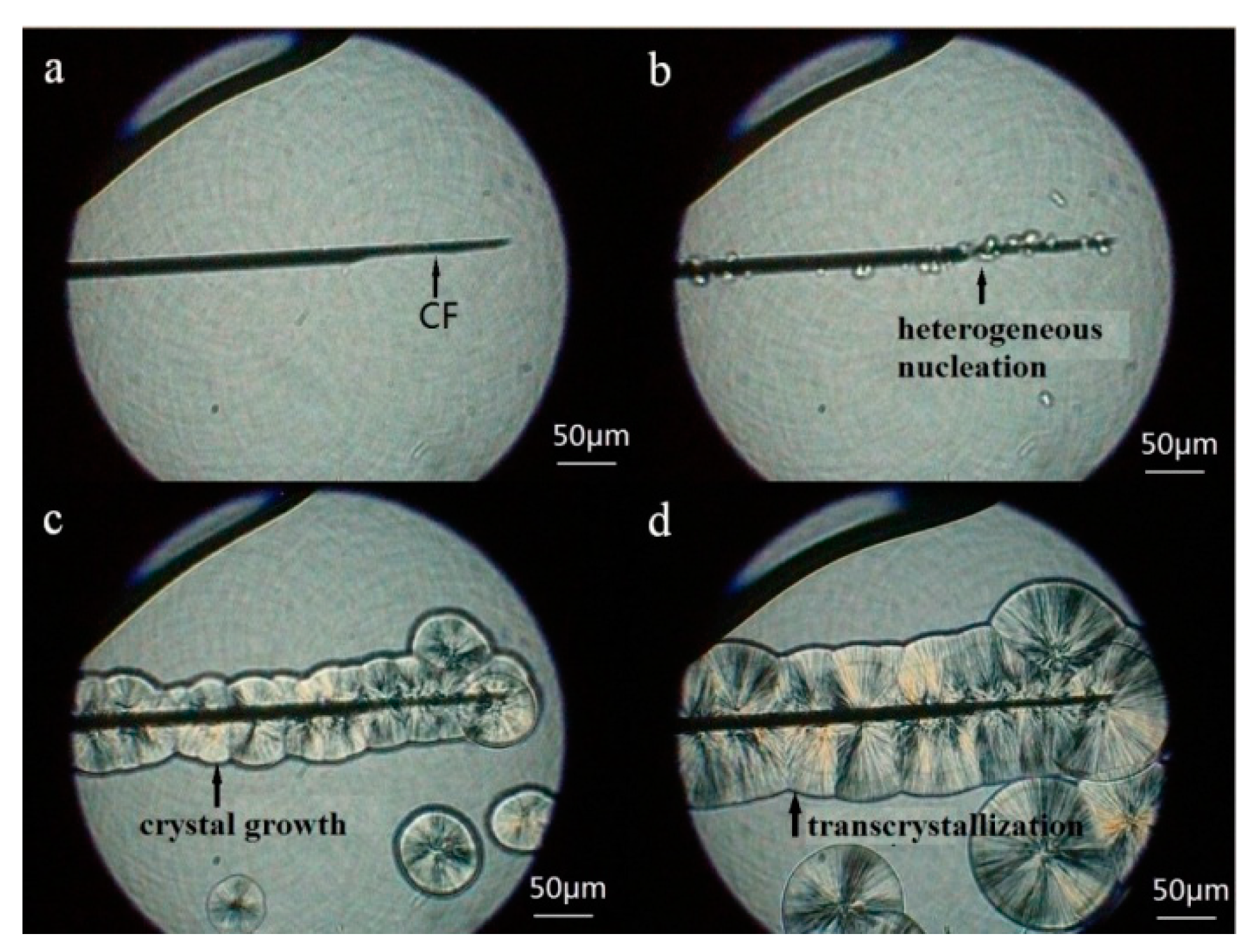
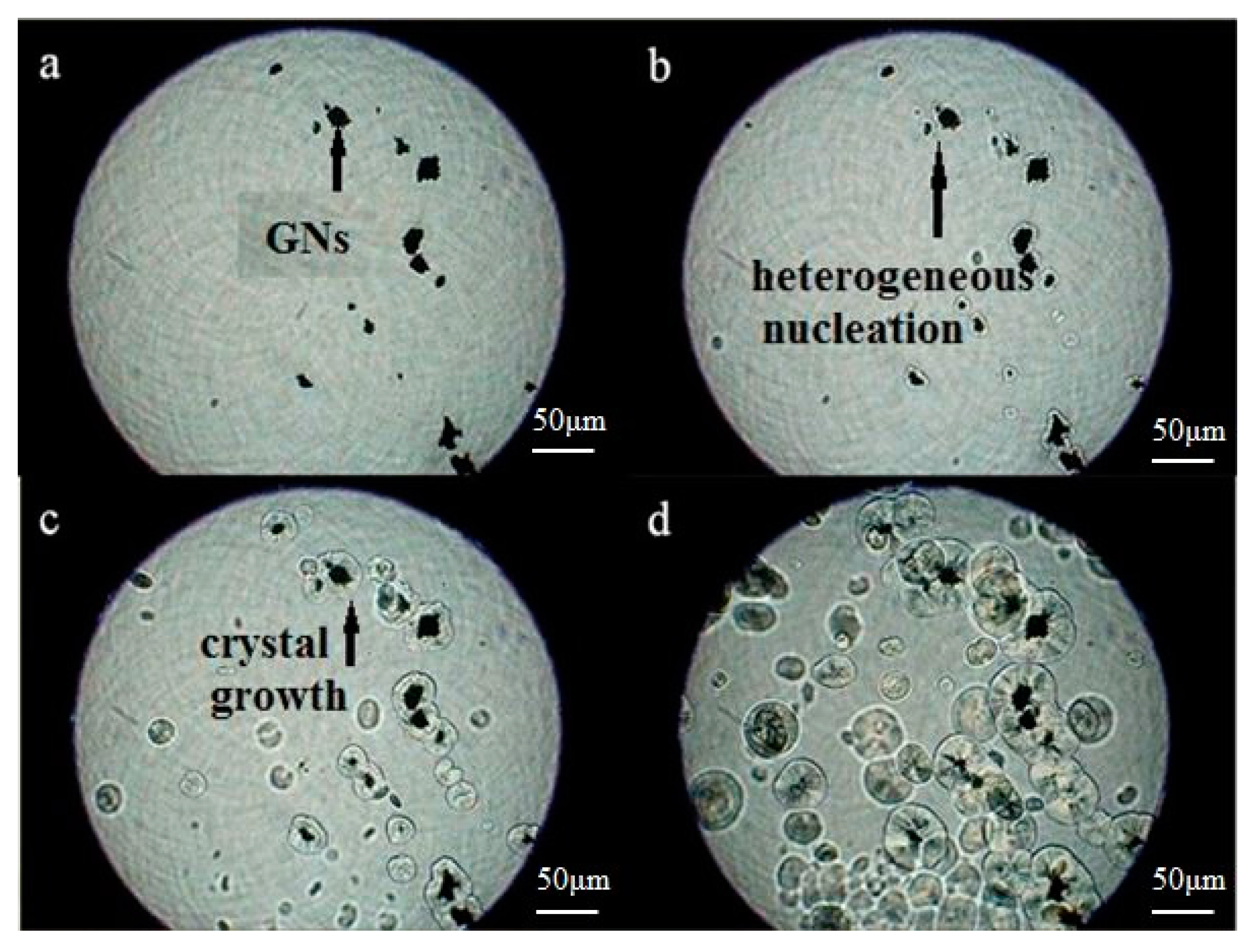
3.1. Performance of Crystallization

| wt% | Tc (°C) | Tonset (°C) | Tonset–Tc (°C) | t1/2 (min) | Xc (%) |
|---|---|---|---|---|---|
| 0 | 111.46 | 116.21 | 4.75 | 0.444 | 40.3 |
| 1 | 124.91 | 129.70 | 4.79 | 0.479 | 38.6 |
| 3 | 127.54 | 132.43 | 4.89 | 0.477 | 38.6 |
| 5 | 129.39 | 135.22 | 5.83 | 0.567 | 45.1 |
| 10 | 132.75 | 138.19 | 5.44 | 0.543 | 44.5 |
| 15 | 133.36 | 139.46 | 6.10 | 0.604 | 45.7 |
| 20 | 135.01 | 140.67 | 5.66 | 0.574 | 45.4 |
| wt% | Tc (°C) | Tonset (°C) | Tonset–Tc (°C) | t1/2 (min) | Xc (%) |
|---|---|---|---|---|---|
| 0 | 111.46 | 116.21 | 4.75 | 0.444 | 40.3 |
| 1 | 118.92 | 122.73 | 3.81 | 0.373 | 38.9 |
| 3 | 119.42 | 123.27 | 3.85 | 0.368 | 39.6 |
| 5 | 120.23 | 123.93 | 3.70 | 0.358 | 39.9 |
| 10 | 120.61 | 124.56 | 3.95 | 0.403 | 40.4 |
| 15 | 120.90 | 125.23 | 4.33 | 0.443 | 41.8 |
| 20 | 122.28 | 126.25 | 3.97 | 0.387 | 41.1 |

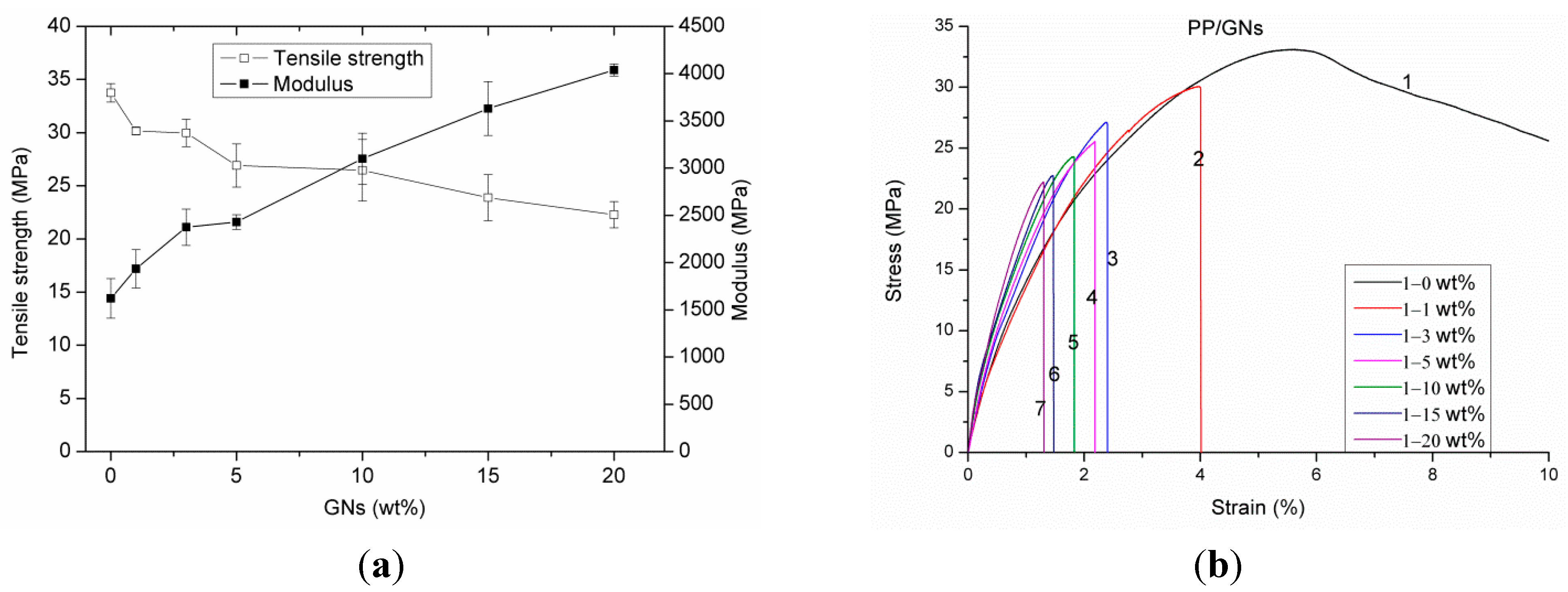
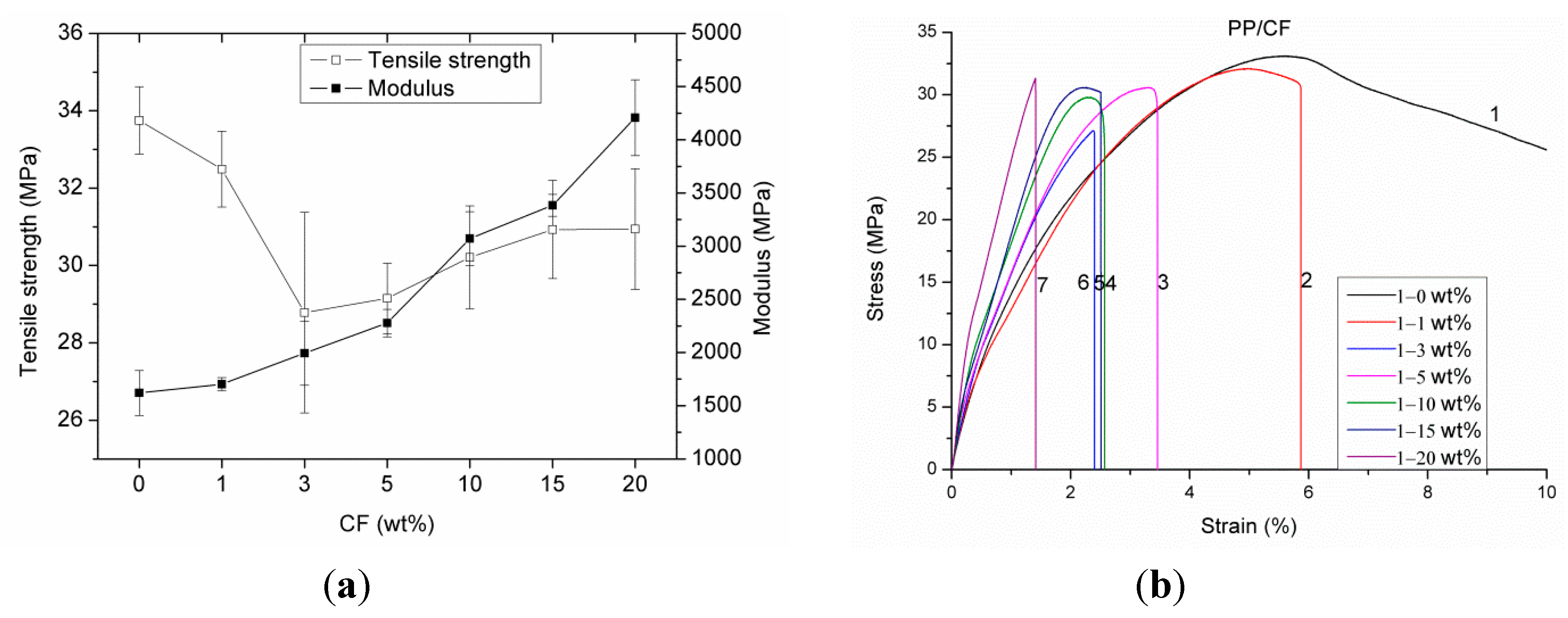
3.2. Performance of Tensile Properties
| Filler (wt%) | GNs | CF | ||||||
|---|---|---|---|---|---|---|---|---|
| Tensile strength (MPa) | Tensile Modulus (MPa) | Elongation (%) | Conductivity (S/m) | Tensile strength (MPa) | Tensile Modulus (MPa) | Elongation (%) | Conductivity (S/m) | |
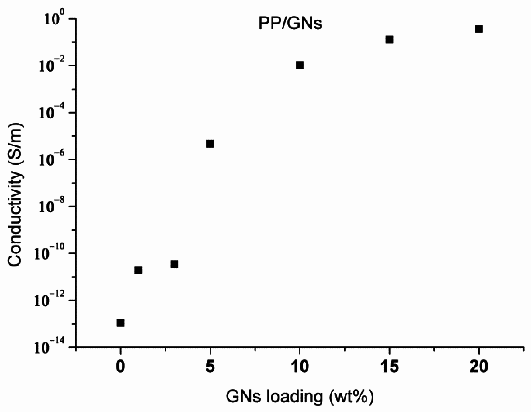
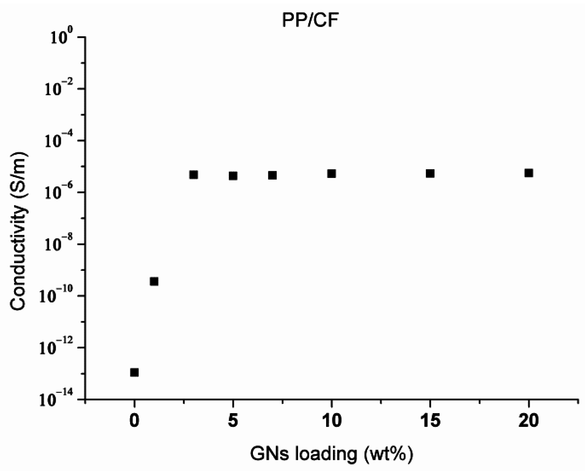
| 0 | 33.75 ± 0.87 | 1621 ± 211 | >100 | 1.2 × 10⁻¹³ ± 1.1 × 10⁻¹³ | 33.75 ± 0.87 | 1621 ± 211 | >100 | 1.2 × 10⁻¹³ ± 1.1 × 10⁻¹³ |
| 1 | 30.16 ± 0.34 | 1934 ± 203 | 3.66 ± 0.75 | 9.2 × 10⁻¹⁰ ± 2.4 × 10⁻¹⁰ | 32.49 ± 0.98 | 1703 ± 60 | 5.75 ± 0.5 | 3.4 × 10⁻⁶ ± 1.2 × 10⁻⁶ |
| 3 | 29.98 ± 1.29 | 2374 ± 192 | 3.07 ± 0.33 | 6.8 × 10⁻¹⁰ ± 1.3 × 10⁻¹⁰ | 28.78 ± 2.59 | 1993 ± 301 | 2.64 ± 0.36 | 3.8 × 10⁻⁶ ± 1.4 × 10⁻⁶ |
| 5 | 26.92 ± 2.03 | 2429 ± 78 | 2.63 ± 0.39 | 2.3 × 10⁻⁵ ± 1.2 × 10⁻⁵ | 29.15 ± 0.91 | 2278 ± 129 | 3.54 ± 0.26 | 3.8 × 10⁻⁶ ± 1.3 × 10⁻⁶ |
| 10 | 26.46 ± 2.89 | 3099 ± 270 | 1.86 ± 0.15 | 1.1 × 10⁻² ± 0.003 | 30.22 ± 1.33 | 3072 ± 252 | 2.59 ± 0.16 | 3.1 × 10⁻⁶ ± 1.1 × 10⁻⁶ |
| 15 | 23.88 ± 2.17 | 3630 ± 280 | 1.54 ± 0.16 | 0.12 ± 0.01 | 30.94 ± 1.27 | 3384 ± 102 | 2.57 ± 013 | 3.2 × 10⁻⁶ ± 1.2 × 10⁻⁶ |
| 20 | 22.28 ± 1.23 | 4037 ± 64 | 1.21 ± 0.21 | 0.36 ± 0.12 | 30.95 ± 1.56 | 4207 ± 357 | 1.62 ± 0.23 | 3.2 × 10⁻⁶ ± 1.3 × 10⁻⁶ |
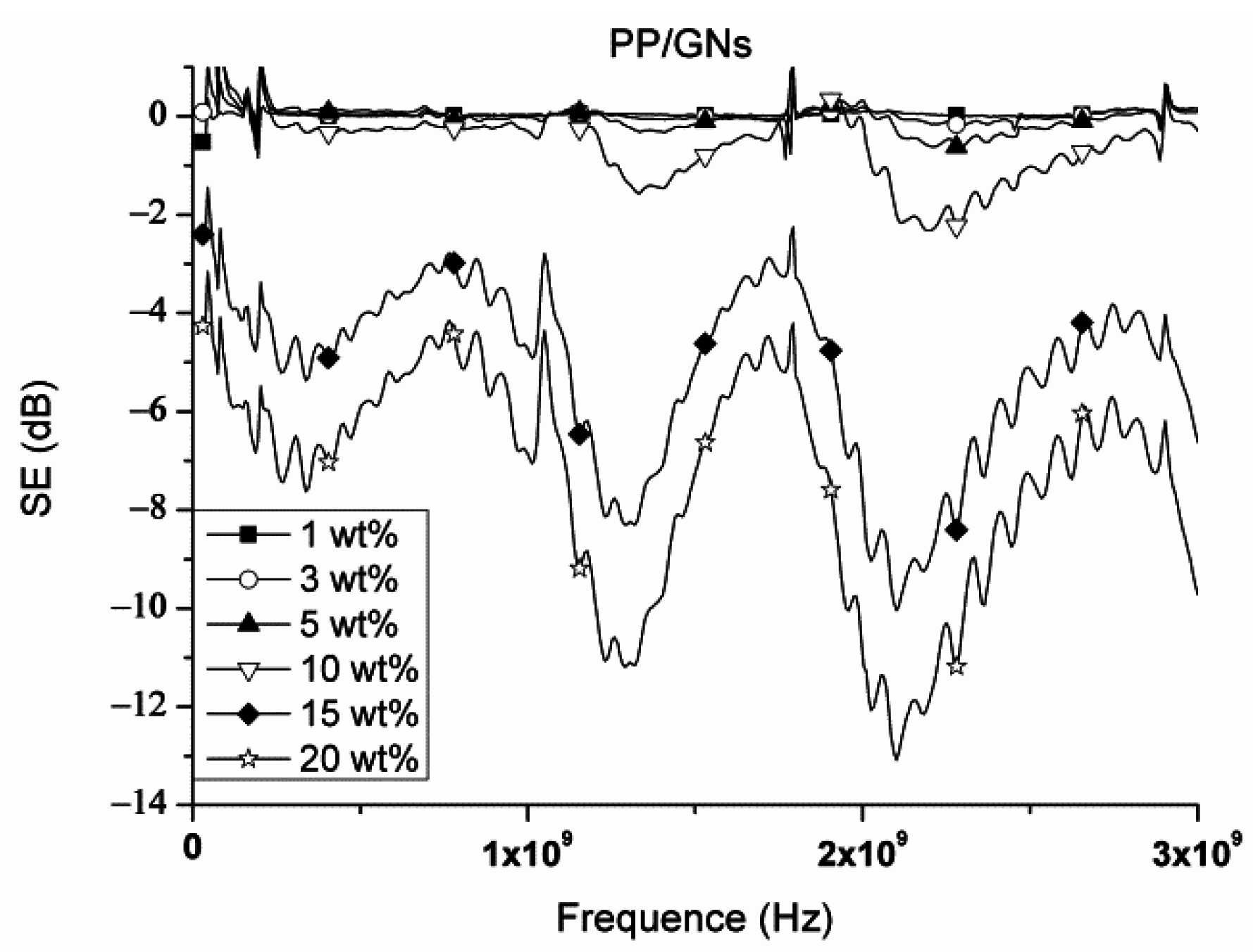
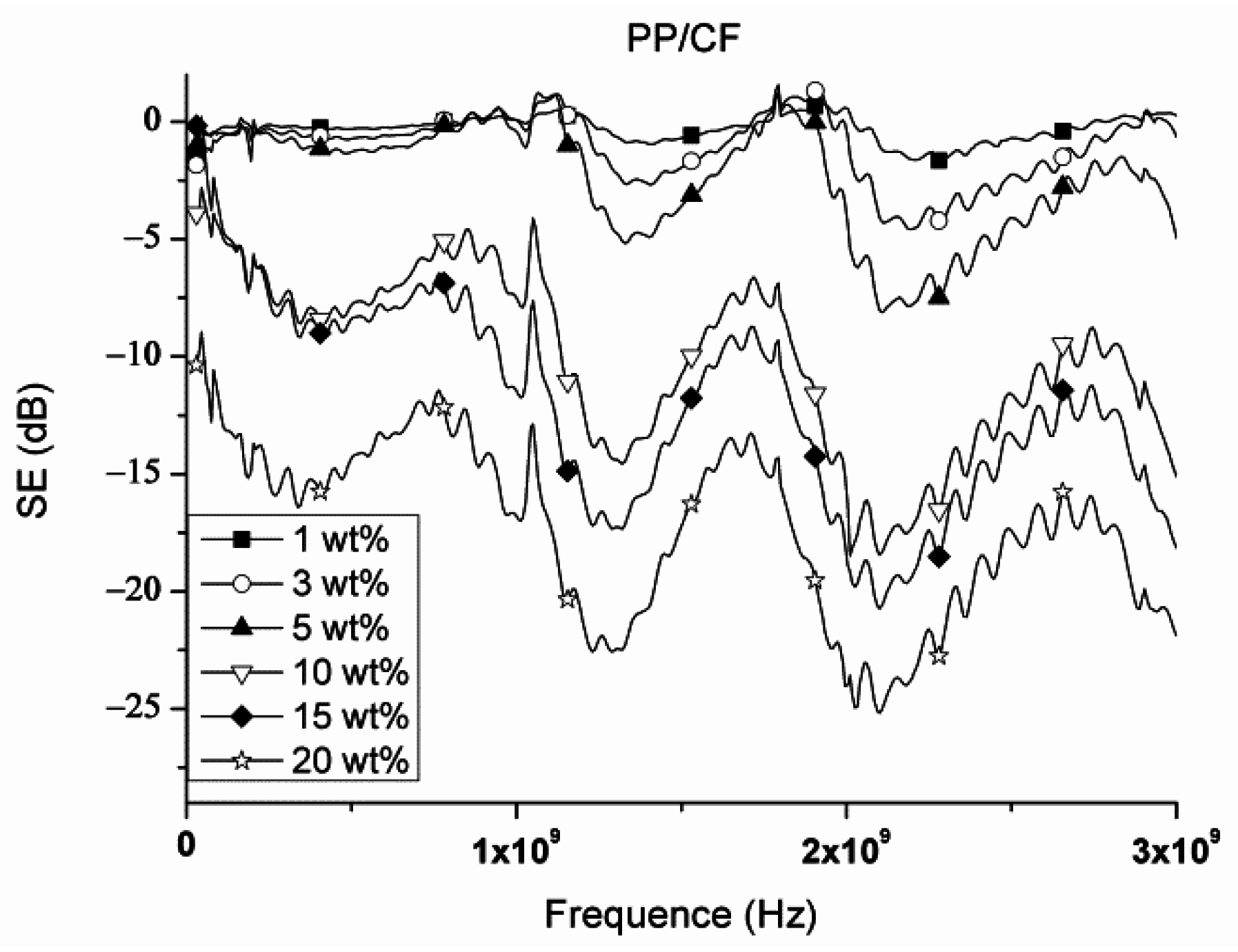
3.3. Performance of Electrical Conductivity and EMI SE
4. Conclusions
Acknowledgments
Author Contributions
Conflicts of Interest
References
- Shen, L.; Wang, F.Q.; Yang, H.; Meng, Q.R. The combined effects of carbon black and carbon fiber on the electrical properties of composites based on polyethylene or polyethylene/polypropylene blend. Polym. Test. 2011, 30, 442–448. [Google Scholar] [CrossRef]
- Huang, J.; Mao, C.; Zhu, Y.; Jiang, W.; Yang, X. Control of carbon nanotubes at the interface of a co-continuous immiscible polymer blend to fabricate conductive composites with ultralow percolation thresholds. Carbon 2014, 73, 267–274. [Google Scholar] [CrossRef]
- Shrivastava, N.K.; Khatua, B.B. Development of electrical conductivity with minimum possible percolation threshold in multi-wall carbon nanotube/polystyrene composites. Carbon 2011, 49, 4571–4579. [Google Scholar] [CrossRef]
- Chen, Y.-J.; Dung, N.D.; Li, Y.-A.; Yip, M.-C.; Hsu, W.-K.; Tai, N.-H. Investigation of the electric conductivity and the electromagnetic interference shielding efficiency of SWCNTs/GNS/PAni nanocomposites. Diamond Relat. Mater. 2011, 20, 1183–1187. [Google Scholar] [CrossRef]
- Zhao, S.; Zhao, H.; Li, G.; Dai, K.; Zheng, G.; Liu, C.; Shen, C. Synergistic effect of carbon fibers on the conductive properties of a segregated carbon black/polypropylene composite. Mater. Lett. 2014, 129, 72–75. [Google Scholar] [CrossRef]
- Calberg, C.; Blacher, S.; Gubbels, F.; Brouers, F.; Deltour, R.; Jerome, R. Electrical and dielectric properties of carbon black filled co-continuous two-phase polymer blends. J. Phys. D 1999, 32, 1517–1525. [Google Scholar] [CrossRef]
- Wen, M.; Sun, X.; Su, L.; Shen, J.; Li, J.; Guo, S. The electrical conductivity of carbon nanotube/carbon black/polypropylene composites prepared through multistage stretching extrusion. Polymer 2012, 53, 1602–1610. [Google Scholar] [CrossRef]
- Drubetski, M.; Siegmann, A.; Narkis, M. Electrical properties of hybrid carbon black/carbon fiber polypropylene composites. J. Mater. Sci. 2006, 42, 1–8. [Google Scholar] [CrossRef]
- Straat, M.; Boldizar, A.; Rigdahl, M.; Hagstrom, B. Improvement of melt spinning properties and conductivity of immiscible polypropylene/polystyrene blends containing carbon black by addition of styrene-ethylene-butene-styrene block copolymer. Polym. Eng. Sci. 2011, 51, 1165–1169. [Google Scholar] [CrossRef]
- Pramanik, P.K.; Khastgir, D.; Saharu, T.N. Conductive nitrile rubber composite containing carbon fillers: Studies on mechanical properties and electrical conductive. Composites 1992, 23, 183–191. [Google Scholar] [CrossRef]
- Thongruang, W.; Spontak, R.J.; Balik, C.M. Correlated electrical conductivity and mechanical property analysis of high-density polyethylene filled with graphite and carbon fiber. Polymer 2002, 43, 2279–2286. [Google Scholar] [CrossRef]
- Xu, H.-P.; Dang, Z.-M. Electrical property and microstructure analysis of poly(vinylidene fluoride)-based composites with different conducting fillers. Chem. Phys. Lett. 2007, 438, 196–202. [Google Scholar] [CrossRef]
- Kalaitzidou, K.; Fukushima, H.; Drzal, L.T. A new compounding method for exfoliated graphite–polypropylene nanocomposites with enhanced flexural properties and lower percolation threshold. Compos. Sci. Technol. 2007, 67, 2045–2051. [Google Scholar] [CrossRef]
- Sengupta, R.; Bhattacharya, M.; Bandyopadhyay, S.; Bhowmick, A.K. A review on the mechanical and electrical properties of graphite and modified graphite reinforced polymer composites. Prog. Polym. Sci. 2011, 36, 638–670. [Google Scholar] [CrossRef]
- McLachlan, D.S.; Chiteme, C.; Park, C.; Wise, K.E.; Lowther, S.E.; Lillehei, P.T.; Siochi, E.J.; Harrison, J.S. AC and DC percolative conductivity of single wall carbon nanotube polymer composites. J. Polym. Sci., Part B: Polym. Phys. 2005, 43, 3273–3287. [Google Scholar] [CrossRef]
- Miyazaki, K.; Okazaki, N.; Nakatani, H. Improvement of electrical conductivity with phase-separation in polyolefin/multiwall carbon nanotube/polyethylene oxide composites. J. Appl. Polym. Sci. 2013, 128, 3751–3757. [Google Scholar] [CrossRef]
- Stankovich, S.; Dikin, D.A.; Dommett, G.H.; Kohlhaas, K.M.; Zimney, E.J.; Stach, E.A.; Piner, R.D.; Nguyen, S.T.; Ruoff, R.S. Graphene-based composite materials. Nature 2006, 442, 282–286. [Google Scholar] [CrossRef] [PubMed]
- Potts, J.R.; Dreyer, D.R.; Bielawski, C.W.; Ruoff, R.S. Graphene-based polymer nanocomposites. Polymer 2011, 52, 5–25. [Google Scholar] [CrossRef]
- Geim, A.K.; Novoselov, K.S. The rise of graphene. Nat. Mater. 2007, 6, 183–191. [Google Scholar] [CrossRef] [PubMed]
- Hsiao, S.-T.; Ma, C.-C.M.; Tien, H.-W.; Liao, W.-H.; Wang, Y.-S.; Li, S.-M.; Huang, Y.-C. Using a non-covalent modification to prepare a high electromagnetic interference shielding performance graphene nanosheet/water-borne polyurethane composite. Carbon 2013, 60, 57–66. [Google Scholar] [CrossRef]
- Zhang, H.-B.; Zheng, W.-G.; Yan, Q.; Yang, Y.; Wang, J.-W.; Lu, Z.-H.; Ji, G.-Y.; Yu, Z.-Z. Electrically conductive polyethylene terephthalate/graphene nanocomposites prepared by melt compounding. Polymer 2010, 51, 1191–1196. [Google Scholar] [CrossRef]
- Lin, Y.; Chen, H.; Chan, C.M.; Wu, J. Nucleating effect of calcium stearate coated CaCO3 nanoparticles on polypropylene. J. Colloid Interface Sci. 2011, 354, 570–576. [Google Scholar] [CrossRef] [PubMed]
- Sui, G.; Fuqua, M.A.; Ulven, C.A.; Zhong, W.H. A plant fiber reinforced polymer composite prepared by a twin-screw extruder. Bioresour. Technol. 2009, 100, 1246–1251. [Google Scholar] [CrossRef] [PubMed]
- Gao, Y.; Wang, Y.; Shi, J.; Bai, H.; Song, B. Functionalized multi-walled carbon nanotubes improve nonisothermal crystallization of poly(ethylene terephthalate). Polym. Test. 2008, 27, 179–188. [Google Scholar] [CrossRef]
- Xu, Y.; Shang, S.; Huang, J. Crystallization behavior of poly(trimethylene terephthalate)-poly(ethylene glycol) segmented copolyesters/multi-walled carbon nanotube nanocomposites. Polym. Test. 2010, 29, 1007–1013. [Google Scholar] [CrossRef]
- Ke, K.; Wang, Y.; Yang, W.; Xie, B.-H.; Yang, M.-B. Crystallization and reinforcement of poly (vinylidene fluoride) nanocomposites: Role of high molecular weight resin and carbon nanotubes. Polym. Test. 2012, 31, 117–126. [Google Scholar] [CrossRef]
- Xu, D.; Wang, Z. Role of multi-wall carbon nanotube network in composites to crystallization of isotactic polypropylene matrix. Polymer 2008, 49, 330–338. [Google Scholar] [CrossRef]
- Razavi-Nouri, M.; Ghorbanzadeh-Ahangari, M.; Fereidoon, A.; Jahanshahi, M. Effect of carbon nanotubes content on crystallization kinetics and morphology of polypropylene. Polym. Test. 2009, 28, 46–52. [Google Scholar] [CrossRef]
- Zhao, S.; Chen, F.; Huang, Y.; Dong, J.-Y.; Han, C.C. Crystallization behaviors in the isotactic polypropylene/graphene composites. Polymer 2014, 55, 4125–4135. [Google Scholar] [CrossRef]
- Korayem, A.H.; Barati, M.R.; Simon, G.P.; Zhao, X.L.; Duan, W.H. Reinforcing brittle and ductile epoxy matrices using carbon nanotubes masterbatch. Composites Part A 2014, 61, 126–133. [Google Scholar] [CrossRef]
- Prashantha, K.; Soulestin, J.; Lacrampe, M.F.; Krawczak, P.; Dupin, G.; Claes, M. Masterbatch-based multi-walled carbon nanotube filled polypropylene nanocomposites: Assessment of rheological and mechanical properties. Compos. Sci. Technol. 2009, 69, 1756–1763. [Google Scholar] [CrossRef]
- Al-Saleh, M.H.; Sundararaj, U. Electromagnetic interference shielding mechanisms of CNT/polymer composites. Carbon 2009, 47, 1738–1746. [Google Scholar] [CrossRef]
- Arjmand, M.; Apperley, T.; Okoniewski, M.; Sundararaj, U. Comparative study of electromagnetic interference shielding properties of injection molded versus compression molded multi-walled carbon nanotube/polystyrene composites. Carbon 2012, 50, 5126–5134. [Google Scholar] [CrossRef]
- Arjmand, M.; Mahmoodi, M.; Gelves, G.A.; Park, S.; Sundararaj, U. Electrical and electromagnetic interference shielding properties of flow-induced oriented carbon nanotubes in polycarbonate. Carbon 2011, 49, 3430–3440. [Google Scholar] [CrossRef]
- Cao, J.-P.; Zhao, J.; Zhao, X.; You, F.; Yu, H.; Hu, G.-H.; Dang, Z.-M. High thermal conductivity and high electrical resistivity of poly(vinylidene fluoride)/polystyrene blends by controlling the localization of hybrid fillers. Compos. Sci. Technol. 2013, 89, 142–148. [Google Scholar] [CrossRef]
- D’Aloia, A.G.; Marra, F.; Tamburrano, A.; de Bellis, G.; Sarto, M.S. Electromagnetic absorbing properties of graphene–polymer composite shields. Carbon 2014, 73, 175–184. [Google Scholar] [CrossRef]
- Mahmoodi, M.; Arjmand, M.; Sundararaj, U.; Park, S. The electrical conductivity and electromagnetic interference shielding of injection molded multi-walled carbon nanotube/polystyrene composites. Carbon 2012, 50, 1455–1464. [Google Scholar] [CrossRef]
- Thomassin, J.-M.; Jerome, C.; Pardoen, T.; Bailly, C.; Huynen, I.; Detrembleur, C. Polymer/carbon based composites as electromagnetic interference (EMI) shielding materials. Mater. Sci. Eng. R 2013, 74, 211–232. [Google Scholar] [CrossRef]
- Bian, J.; Lin, H.L.; He, F.X.; Wei, X.W.; Chang, I.T.; Sancaktar, E. Fabrication of microwave exfoliated graphite oxide reinforced thermoplastic polyurethane nanocomposites: Effects of filler on morphology, mechanical, thermal and conductive properties. Composites Part A 2013, 47, 72–82. [Google Scholar] [CrossRef]
- Deetuam, C.; Samthong, C.; Thongyai, S.; Praserthdam, P.; Somwangthanaroj, A. Synthesis of well dispersed graphene in conjugated poly(3,4-ethylenedioxythiophene):polystyrene sulfonate via click chemistry. Compos. Sci. Technol. 2014, 93, 1–8. [Google Scholar] [CrossRef]
- Garzon, C.; Palza, H. Electrical behavior of polypropylene composites melt mixed with carbon-based particles: Effect of the kind of particle and annealing process. Compos. Sci. Technol. 2014, 99, 117–123. [Google Scholar] [CrossRef]
- Noel, A.; Faucheu, J.; Rieu, M.; Viricelle, J.-P.; Bourgeat-Lami, E. Tunable architecture for flexible and highly conductive graphene–polymer composites. Compos. Sci. Technol. 2014, 95, 82–88. [Google Scholar] [CrossRef]
- Zhao, S.; Chen, F.; Zhao, C.; Huang, Y.; Dong, J.-Y.; Han, C.C. Interpenetrating network formation in isotactic polypropylene/graphene composites. Polymer 2013, 54, 3680–3690. [Google Scholar] [CrossRef]
© 2015 by the authors; licensee MDPI, Basel, Switzerland. This article is an open access article distributed under the terms and conditions of the Creative Commons Attribution license (http://creativecommons.org/licenses/by/4.0/).
Share and Cite
Huang, C.-L.; Lou, C.-W.; Liu, C.-F.; Huang, C.-H.; Song, X.-M.; Lin, J.-H. Polypropylene/Graphene and Polypropylene/Carbon Fiber Conductive Composites: Mechanical, Crystallization and Electromagnetic Properties. Appl. Sci. 2015, 5, 1196-1210. https://doi.org/10.3390/app5041196
Huang C-L, Lou C-W, Liu C-F, Huang C-H, Song X-M, Lin J-H. Polypropylene/Graphene and Polypropylene/Carbon Fiber Conductive Composites: Mechanical, Crystallization and Electromagnetic Properties. Applied Sciences. 2015; 5(4):1196-1210. https://doi.org/10.3390/app5041196
Chicago/Turabian StyleHuang, Chien-Lin, Ching-Wen Lou, Chi-Fan Liu, Chen-Hung Huang, Xiao-Min Song, and Jia-Horng Lin. 2015. "Polypropylene/Graphene and Polypropylene/Carbon Fiber Conductive Composites: Mechanical, Crystallization and Electromagnetic Properties" Applied Sciences 5, no. 4: 1196-1210. https://doi.org/10.3390/app5041196
APA StyleHuang, C.-L., Lou, C.-W., Liu, C.-F., Huang, C.-H., Song, X.-M., & Lin, J.-H. (2015). Polypropylene/Graphene and Polypropylene/Carbon Fiber Conductive Composites: Mechanical, Crystallization and Electromagnetic Properties. Applied Sciences, 5(4), 1196-1210. https://doi.org/10.3390/app5041196