Article

Performance Evaluation of sCO2–Hydrocarbon Mixtures in SBC-PTES Systems: A Parametric Thermo-Economic Study


by
Paul Tafur-Escanta
1,2,*,
Luis Garzón-Pérez
3,
Lizbeth Barrera-Cifuentes
4,
Luis Coco-Enriquez
5 and
Robert Valencia-Chapi
2,3,*
1
Facultad de Ingeniería en Ciencias Agropecuarias y Ambientales, Universidad Técnica del Norte, Ibarra 100150, Ecuador
2
Generación y Almacenamiento Energético para el Norte (GYAE4N) Research Group at REDU, Urcuquí 100115, Ecuador
3
Facultad de Ingeniería en Ciencias Aplicadas, Universidad Técnica del Norte, Ibarra 100150, Ecuador
4
Facultad de Ciencias de Medio Ambiente, Universidad Tecnológica Indoamérica, Quito 170103, Ecuador
5
ETSI Industriales, Universidad Politécnica de Madrid, 28006 Madrid, Spain
*
Authors to whom correspondence should be addressed.
Appl. Sci. 2026, 16(9), 4068; https://doi.org/10.3390/app16094068
Submission received: 5 March 2026 / Revised: 20 March 2026 / Accepted: 23 March 2026 / Published: 22 April 2026
(This article belongs to the Special Issue New Challenges in Thermodynamics)

Abstract

The development of efficient and economically viable energy storage technologies is key to the integration of renewable energies. This study evaluates the thermo-economic performance of hydrocarbons as working fluids in PTES systems based on a simple Brayton cycle (SBC). Different hydrocarbon mixtures are analyzed to determine their impact on efficiency and costs, identifying optimal operating conditions and combinations that improve system performance and viability. The objective is to identify the optimal candidate and operating conditions for enhanced cost-effectiveness. A multivariable optimization was performed using a validated thermodynamic model, integrated with an economic evaluation framework. Key decision variables included pressure ratios, turbine inlet temperatures, and heat exchanger performance parameters, while several sCO2–hydrocarbon mixtures were evaluated as working fluids. Energy and exergy analyses were coupled with component-level cost correlations to determine round-trip efficiency, specific investment cost, and levelized cost of storage. The findings indicate that the CO2/C2H6 (60/40) mixture provides the best overall performance, achieving a round-trip efficiency of 54.38% and a levelized cost of storage of 137.1 $/MWh, outperforming pure CO2. Fluid selection exerts a substantial influence on both thermodynamic and economic indicators, with performance exhibiting a pronounced dependency on critical temperature, molecular complexity, and operating pressure levels. Sensitivity analyses indicate that improvements in heat exchanger effectiveness and turbomachinery efficiency yield substantial reductions in total system cost. The findings indicate that the appropriate alignment of hydrocarbon properties with system design parameters can significantly enhance the feasibility of PTES, offering a technically viable and economically competitive pathway for large-scale energy storage applications.

1. Introduction

Recently, the deployment of electricity storage technologies has insufficiently kept pace with the rapid growth in renewable energy generation [1,2]. The primary constraints on the large-scale implementation of electrical energy storage projects are associated with land requirements, high capital costs and the relatively short operational lifetime of storage equipment [3,4]. Considering these challenges, recent studies have investigated alternative integration pathways employing Pumped Thermal Energy Storage (PTES) systems, highlighting their potential as a complementary solution to conventional battery-based storage technologies, particularly for electricity generated from renewable sources [5,6,7]. Thermal energy storage systems employ heat pump cycles to convert electrical energy into thermal energy, store it in a reservoir, and reconvert it into electricity when required, enabling efficient, flexible, and environmentally benign grid support [8,9,10].
The Brayton cycle has been analyzed and applied in extensive studies due to its operational simplicity, compact layout, with thermal efficiency values typically ranging from 30% to 50% depending on the working fluid and operating conditions [11,12,13]. The literature has proposed multiple configurations of the Brayton cycle [5,8,14], and some of these enhance cycle efficiency through the incorporation of recompression processes and multi-stage regeneration [15]. Other studies have investigated Brayton cycle arrangements featuring both recuperation and recompression, particularly in the context of pumped thermal energy storage (PTES) applications [7,16]. A considerable number of investigations have been conducted which analyze multiple design and operational parameters of energy storage cycles with the objective of optimizing thermodynamic performance, particularly round-trip efficiency. These investigations have also incorporated techno-economic criteria, with emphasis on the levelized cost of storage (LCOS) [3,17,18]. Zhao et al. [12] performed multi-objective optimization of Brayton PTES systems and reported optimal LCOS values ranging from 130 to 230 $/MWh with corresponding round-trip efficiencies of 55–62%, while Shalaby et al. [11] demonstrated that CO2-based mixtures can enhance cycle performance by up to 8% compared to pure CO2 at optimal pressure ratios of 2.5–3.5. Furthermore, experimental evidence has demonstrated that recompression variants can achieve efficiencies of approximately 69.38% by increasing charge and discharge temperature levels. This has been shown to outperform basic non-recuperated configurations by up to 33%, with Tafur-Escanta et al. [18] reporting that optimal recompression fractions between 0.07 and 0.25 and compressor inlet pressures of 76–77 bar are critical for achieving this enhanced performance.
Recent studies demonstrate that recompression Brayton cycles using supercritical CO2 (s-CO2) offer a competitive solution for long-duration thermal energy storage, with applications reported in nuclear, concentrated solar power systems, photovoltaics and wind power [19,20,21]. Research on s-CO2-based gas mixtures, such as CO2/Xe and CO2/Kr, aims to optimize the efficiency-cost trade-off and system energy density. For instance, CO2/Kr (75/25) achieves a 61.2% round-trip efficiency, outperforming pure s-CO2, while CO2/Xe (20/80) attains the lowest reported LCOS at 133.60 USD/MWh [8]. These results are consistent with the comprehensive study by Yu et al. (2020) [22], which thermodynamically analyzed seven CO2-based mixtures CO2/Xe, CO2/Kr, CO2/Ar, CO2/N2, and CO2/He under a fixed compressor inlet temperature. These findings are consistent with the study by Yu et al. [22], which demonstrated that the performance of Brayton cycles strongly depends on the critical properties and composition of the working fluid. Hydrocarbons such as methane, ethane, and propane exhibit favourable thermophysical properties, including appropriate critical temperatures, high specific heat capacity, and tunable density, which can enhance thermal matching and reduce irreversibilities within the cycle [21,23]. Moreover, these fluids present environmental advantages, such as negligible ozone depletion potential and relatively low global warming potential compared to synthetic refrigerants [23,24]. Existing studies have mainly addressed thermophysical characterization or alternative applications, leaving a significant gap in their systematic integration into PTES systems. Accordingly, the present study conducts a parametric thermo-economic assessment of sCO2–hydrocarbon mixtures such as ethane, methane and propane, in simple Brayton cycle PTES systems to evaluate their potential for improving efficiency and reducing storage costs.
Among thermo-mechanical concepts, Pumped Thermal Energy Storage (PTES) systems based on Brayton cycles have emerged as a promising solution for large-scale energy storage due to their geographical flexibility and projected round-trip efficiencies in the range of 50–75% [25,26]. Two main configurations have been extensively investigated [27]. Brayton PTES systems typically operate with inert gases such as argon or nitrogen and can be integrated with packed-bed or liquid-tank thermal storage, achieving theoretical efficiencies up to 67% at temperatures between 600 and 1000 °C [28,29]. In contrast, transcritical CO2 PTES systems configurations have demonstrated round-trip efficiencies of up to 65% in large-scale systems, while advanced multi-tank layouts improve thermal matching with the variable specific heat of CO2 and reduce irreversibilities [16,30]. In this context, the sCO2–hydrocarbon mixtures represent an alternative in Brayton-based PTES systems configurations to tailor thermophysical properties, reduce irreversibilities, and enhance thermo-economic performance.
A parametric assessment of pumped thermal energy storage (PTES) systems based on Brayton cycles requires the systematic evaluation of thermodynamic and design parameters [7]. In the context of simple Brayton cycle layouts, the fundamental variables to be considered are the compression/expansion ratio, the maximum and minimum cycle temperatures, the selected working fluid, and, most crucially, the isentropic and polytropic efficiencies of compressors and expanders. These considerations are particularly relevant considering the high back work ratio inherent to these systems [5]. In recompression Brayton cycle (RBC) configurations, the analysis is extended to include the recompressed mass flow fractions during charge and discharge ( γ c h g , γ d i s ), which effectively reduce net compression work and enhance thermal matching with the storage subsystem. In this context, supercritical CO2 is commonly adopted as the working fluid due to its favourable thermophysical properties [3,16]. Recent multi-objective optimization studies of supercritical CO2 RBC-PTES systems highlight a clear trade-off between round-trip efficiency ( η R T ) and levelized cost of storage (LCOS). Minimum LCOS values of 148.72 USD/MWh are obtained at η R T 57.1 % , whereas efficiency-oriented designs achieve η R T up to 61.5% at an LCOS of 158.40 USD/MWh, under optimal compressor inlet pressures of 76–77 bar, turbine inlet temperatures of 953–993 K, and charge fractions ranging from 0.07 to 0.25 [18]. The resulting increase in effective energy density is primarily associated with reduced thermodynamic irreversibility and improved integration with sensible thermal energy storage.
This study presents a thermo-economic evaluation of a pumped thermal energy storage (PTES) system based on a simple Brayton cycle (SBC), employing supercritical CO2 (s-CO2)–hydrocarbon mixtures (ethane, methane, and propane) as working fluids. The main contributions of this work are three-fold: (i) the assessment of s-CO2–hydrocarbon mixtures as alternative working fluids for SBC-PTES systems; (ii) a comprehensive thermo-economic analysis based on key performance indicators, including round-trip efficiency and levelized cost of storage (LCOS); and (iii) a sensitivity analysis to quantify the influence of critical design parameters, such as pinch point temperature and heat exchanger effectiveness, on system performance.
The remainder of this paper is organized as follows. Section 2 describes the materials and methods, including system configuration, working fluid selection, operating conditions, and the optimization framework. Section 3 presents and discusses the results, while Section 4 summarizes the main conclusions and outlines directions for future work.

2. Materials and Methods

2.1. System Description

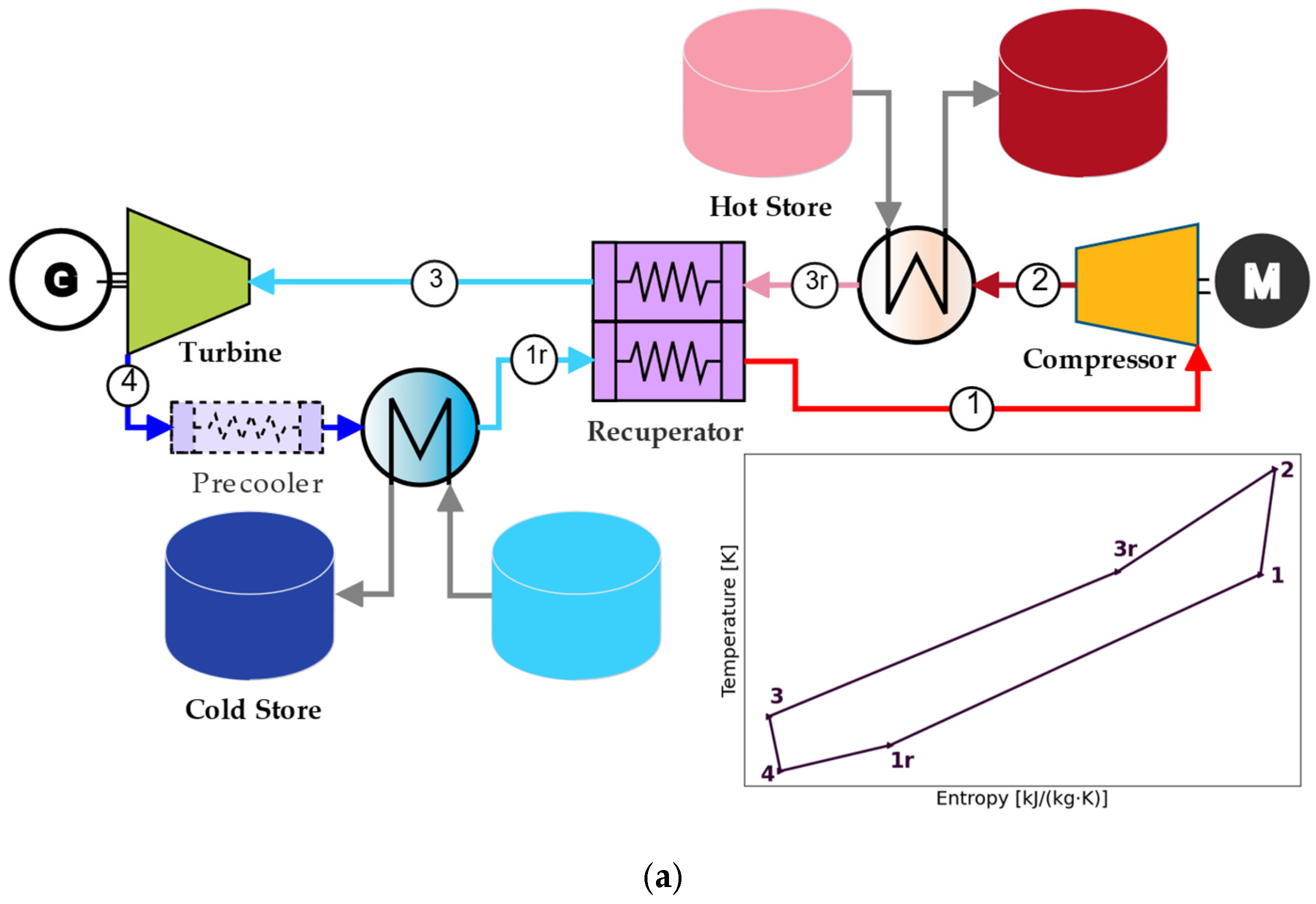
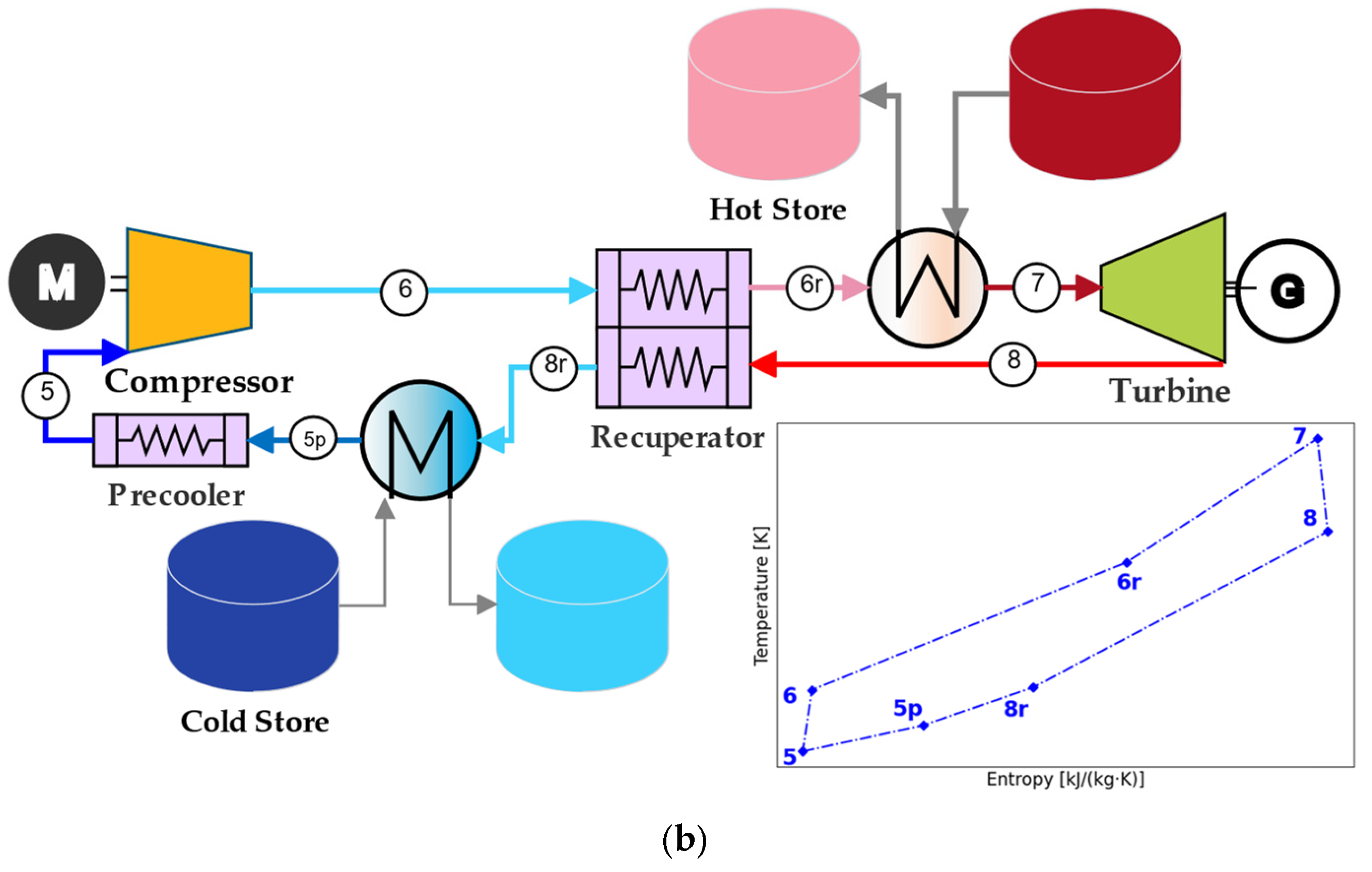
The present work analyses a pumped thermal energy storage configuration operating on a simple Brayton cycle, as illustrated in Figure 1. During the charging mode (see Figure 1a), the system functions through an enhanced Brayton arrangement that improves overall efficiency by recovering and reusing thermal energy from available waste-heat sources. A fundamental element of the cycle under discussion is the recuperator, whose function is to recover heat internally by means of the transfer of energy from the turbine exhaust (hot stream) to the compressed working fluid leaving the compressor (cold stream). The thermodynamic interactions associated with this internal heat exchange are further detailed in states 6 → 6r and 8 → 8r of the discharging configuration shown in Figure 1b. It is imperative to elucidate that the precooler functions exclusively during the discharging stage; consequently, it is depicted with dashed lines in the charging diagram. In the process of discharging, the working fluid must be able to reject heat before entering the main compressor. This requirement is achieved through a water-based crossflow heat exchange process within the precooler. This thermal management strategy is pivotal in ensuring the stability and efficiency of the cycle operation. In essence, the performance of the Brayton-based PTES system is governed by a reduced number of key operating variables, primarily the compressor inlet temperature and the pressure ratio. These require coordinated optimization to maximize energy recovery efficiency.
The system reaches a maximum operating temperature of 760 °C in the hot storage tank, a condition met under the operating regime considered in this study, characterized by a turbine inlet temperature of 700 °C during the discharge stage. To ensure compliance with this thermal condition, a molten salt mixture composed of ZnCl2/NaCl/KCl is used as the heat transfer fluid, with mass proportions of 44.3%, 13.8%, and 41.9%, respectively. This selection guarantees adequate thermal stability and efficient performance within the system’s operating temperature range. The operating interval (approximately 10–11 h of charging and discharging) is consistent with the use of sensible thermal storage using molten salts, which allows operation on extended hourly scales due to its high heat capacity and thermal stability at high temperatures, thus justifying the sizing adopted for the PTES system. The main design parameters of the thermal storage system (TES) are presented in Table 1.

2.2. Input Assumptions

The main modelling assumptions are summarized in Table 2. This table presents a compendium of the principal inputs and the constraints employed in the thermodynamic simulations of the SBC-PTES system.
The discharge stage was defined as a net electrical power output of 25 MW. During the charging and discharging stage, the temperatures of the compressor inlet and the turbine inlet were found to be optimal. The compressor outlet pressure was set at a maximum of 30 MPa. The efficiencies of the components were assumed to be constant at 0.80 for the compressors and 0.85 for the turbines, a value consistent with the literature [14,31,32,33,34,35].
It was hypothesized that pressure drops would amount to 1% of the inlet pressure across recuperators and precoolers [36,37]. A sensitivity analysis was conducted for the purpose of evaluating the influence of the pinch point on the performance of the SBC-PTES system.
Table 2. Input assumptions.
ParameterValueUnits
Net power discharge W ˙ n e t d i s 25MW
Compressor inlet pressure (charging and discharging stage) P 1   &   P 5 OptimizedMPa
Compressor outlet pressure (charging and discharging stage) P 2   &   P 6 30MPa
Compressor inlet temperature (charging and discharging stage) T 1   &   T 5 OptimizedK
Turbine inlet temperature (charging and discharging stage) T 3   &   T 7 OptimizedK
Compressor efficiency [14,32,33,34,35] η c 0.80-
Turbine efficiency [14,32,33,35] η t 0.85-
Compression ratio (charging and discharging stage) r p c h g   &   r p d i s Optimized-
Pressure drops for recuperator [36,37] Δ P / P R 1%
Pressure drops for precooler [36,37] Δ P / P P C 1%
Pinch point Δ T m i n 2–25K
The system was conceptualized with a design objective of a discharge power output of 25 MW, accompanied by a charging duration of 11 h. The duration of the discharge process was not predetermined but instead exhibited variation based on the accumulated energy storage capacity inherent to each design configuration. The model is operational in steady-state conditions; however, it does not consider thermal or standby losses incurred by storage tanks.
In order to achieve the objective of this work, it was hypothesized that the maximum turbine inlet temperature recorded was 973.15 K during the discharging stage. To ensure that the required operating temperature of the turbine inlet is satisfied, it has been determined that the ZnCl2/NaCl/KCl molten salt (a mixture of 44.3% ZnCl2, 13.8% NaCl, and 41.9% KCl) should be used as the heat transfer fluid in the thermal energy storage system. The maximum operating temperature of this salt is greater than 1073.15 K [38,39].

2.3. Working Fluid

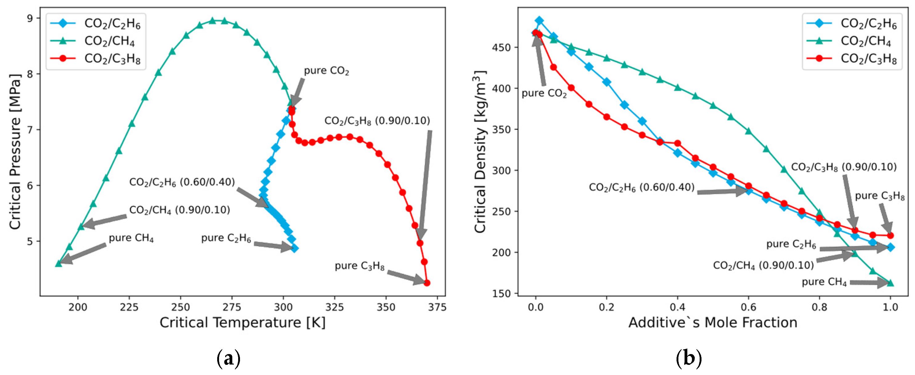
In this work, the simple Brayton cycle employs supercritical CO2 and sCO2–hydrocarbon mixtures as the working fluid. As demonstrated in Figure 2, the variation in the substance’s thermophysical properties is exhibited, particularly about the critical temperature, critical pressure, and critical density, which are contingent on the additive’s mole fraction. These thermophysical properties were obtained from the REFPROP thermodynamic database [39], ensuring the accuracy and consistency of the data used in the analysis. Figure 2a demonstrates the critical pressure in relation to critical temperature for the binary mixtures CO2/CH4, CO2/C2H6, and CO2/C3H8 across the complete composition range. The three curves converge at a single point corresponding to pure CO2; from this common state, the mole fraction of each hydrocarbon increases along its respective curve until reaching the critical point of the pure hydrocarbon at the end of each trajectory. As the hydrocarbon fraction increases, the CO2/CH4 mixture initially exhibits a significant rise in critical pressure, reaching a maximum at intermediate compositions, followed by a decline toward the lower critical pressure characteristic of pure methane. The CO2/C2H6 system displays a smoother, moderately non-linear trend, with a slight pressure increase near the CO2-rich region and a subsequent decrease as the composition approaches pure ethane. Conversely, the CO2/C3H8 mixture exhibits a comparatively extensive pressure plateau at intermediate temperatures prior to a marked reduction in critical pressure as the system approaches the critical conditions of pure propane. The figure provides a comprehensive representation of the non-linear evolution of the critical locus as the hydrocarbon mole fraction increases from the CO2-rich limit to the pure hydrocarbon limit for each binary mixture. For the compositions that are highlighted, the CO2/C2H6 (60/40) ratio is found in the intermediate region, with a moderate critical temperature (270–280 K) and pressure (5.5–6 MPa), indicating balanced component effects. The CO2/CH4 (90/10) mixture, which is closer to the CO2-rich region, shows relatively low critical temperatures (210–220 K) but elevated pressures (5.5 MPa). This reflects strong pressure sensitivity to the methane addition. In contrast, CO2/C3H8 (90/10) exhibits higher critical temperatures (300–310 K) and pressures (7–7.5 MPa), indicative of the influence of propane. It is evident from the points that the critical point of the mixture is subject to variation depending on the composition and hydrocarbon type.
As illustrated in Figure 2b, the critical density of binary mixtures of CO2 with CH4, C2H6, and C3H8 is shown as a function of the hydrocarbon mole fraction. In all cases, the critical density decreases monotonically as the concentration of the hydrocarbon increases from 0 (pure CO2, ≈460–470 kg·m−3) to 1 (pure hydrocarbon). However, the magnitude and curvature of this reduction are dependent upon the specific additive. The CO2/CH4 mixture demonstrates the most significant overall decrease, particularly at high methane fractions (x > 0.6), reaching the lowest critical density values among the mixtures. The CO2/C2H6 mixture displays an intermediate and relatively smooth decline across the entire composition range, while the CO2/C3H8 mixture shows a sharper initial drop at low propane fractions followed by a more moderate decrease at higher compositions. These trends underscore the profound compositional dependence of the critical density and the consequential influence of the molecular nature of the hydrocarbon on the mixture’s critical behaviour. For the selected compositions, the CO2/C2H6 (60/40) mixture exhibits an intermediate critical density of approximately 270–280 kg/m3, consistent with its smooth and gradual decline across composition. The CO2/CH4 (90/10) mixture, which remains in the proximity of the CO2-rich region, exhibits a comparatively elevated critical density (440–450 kg/m3), suggesting a marginal impact of methane at low fractions. Conversely, the CO2/C3H8 (90/10) mixture exhibited a more pronounced reduction, with critical density values ranging from approximately 380 to 400 kg/m3. This observation is indicative of the more substantial influence of propane, even at low concentrations. The representative points highlight the differing sensitivities of each mixture to composition changes.

2.4. Thermodynamic Analysis

The concept of “exergetic efficiency of the cycle” is delineated as the ratio of the coefficient of performance (COP) of the heat pump to the equivalent Carnot COP of the cycle for the charge stage [8,40]. The formulation presented in Equation (1) is defined by the following parameters.
η e x c h g = C O P H P c h g C O P E q C a r n o t c h g  
In the present context, the term C O P E q C a r n o t c h g is employed to signify the equivalent Carnot COP of the cycle for the charge stage [8,21,40,41]. This quantity is calculated using Equation (2).
C O P E q C a r n o t c h g = 1 1 T a b s c h g T r e j c h g  
In the framework of the charging stage, the temperature at which heat is absorbed and the temperature at which heat is rejected can be represented by the following parameters: T a b s c h g , while T r e j c h g respectively. To utilize the previously mentioned formula, it is necessary to determine T a b s c h g and T r e j c h g using Equations (3) and (4).
T a b s c h g = 4 1 r T · d s s 1 r s 4  
T r e j c h g = 2 3 r T · d s s 3 r s 2
The exergy destruction rate of the components of the cycle under examination is represented by the following Equations (5)–(9).
E ˙ D h o t   t a n k c h g = m ˙ m s c h g · e m s   i n c h g e m s   o u t c h g + m ˙ m i x c h g · e 2 e 3 r
E ˙ D c o l d   t a n k c h g = m ˙ w c h g · e w   i n c h g e w   o u t c h g + m ˙ m i x c h g · e 4 e 1 r
E ˙ D t u r c h g = m ˙ m i x c h g · e 3 e 4 W ˙ t u r c h g
E ˙ D c o m c h g = m ˙ m i x c h g · e 1 e 2 W ˙ c o m c h g
E ˙ D r e c c h g = m ˙ m i x c h g · e 1 r e 1 + e 3 r e 3
η e x d i s = η t h d i s η E q C a r n o t d i s  
In accordance with the findings outlined in the extant literature [40,42], the exergy efficiency of the cycle in the discharge stage is delineated by the following Equation (10). This equation stipulates the relationship between the thermal efficiency and the equivalent Carnot efficiency, thereby defining the exergy efficiency of the cycle in the discharge stage.
The value of η E q C a r n o t d i s denotes the equivalent Carnot efficiency of the cycle during its discharge stage [40,42]. The efficiency of the process can be measured using the following Equation (11).
η E q C a r n o t d i s = 1 T r e j d i s T a b s d i s  
As illustrated in Equations (12) and (13), the term T a b d d i s serves to indicate the specific temperature at which heat is absorbed, whereas T r e j d i s is employed to denote the temperature at which heat is rejected, and both of these temperatures are defined within the context of the discharge stage. The values of these temperatures are determined through the utilization of the following equations:
T a b s d i s = 6 r 7 T · d s s 7 s 6 r
T r e j d i s = 8 r 5 T · d s s 5 s 8 r

2.5. Costs Analysis

The estimation of costs was conducted utilizing power-law correlations that have been validated in preceding studies [8,43]. The calculation of the costs associated with the heat recuperators, turbine, compressors, gearbox and generator was performed by utilizing Equations (14) and (15).
C = a · S P b · f T  
In this context, “ a ” and “ b ” are known as the adjustment coefficients. “ S P ” is the abbreviation for “scaling parameter”. f T is the component of the scaling parameter that is determined by Equation (10). The “ C ” in this equation is the component cost.
f T = 1                                               i f   T m a x < T b p 1 + c · T m a x T b p + d · T m a x T b p 2             i f   T m a x T b p  
The temperature breakpoint, denoted by T b p , is conventionally established at 550 °C. The fit coefficients, a and b , are utilized to ascertain the maximum temperature rating of the component, T m a x .
As demonstrated in the reference [8,43], the fitting coefficients a ,   b ,   c and d are provided for the various components of the power cycle.
The financial outlay required for the acquisition of hot and cold storage tanks is determined by utilizing Equations (16) and (17), respectively [44].
C t a n k h o t = 510 · V m s  
C t a n k c o l d = 204 · V w  
where V m s and V w represents the volume of molten salt in the hot tank and the volume of water in the cold tank, respectively.
The levelized cost of electricity (LCOE) method was devised to enable the facilitation of a meaningful financial comparison between the financial costs associated with electricity generation using renewable sources and those associated with conventional technologies. It is evident that the framework under discussion gave rise to the concept of LCOS, which adapts the LCOE methodology for the evaluation of energy storage systems [8,45]. The calculation of LCOS may be facilitated by utilizing the following Equation (18), the validity of which has been substantiated in the extant scientific literature [46,47]:
L C O S = C A P E X E ˙ d i s · n N 1 1 + r n + O P E X E ˙ d i s + C e l e c η r t
The discount rate ( r ), the specific year of operation ( n ), and the lifetime of technology ( N ) are the key variables to consider [48,49]. The initial financial outlay required for the acquisition of the necessary equipment is referred to as the capital expenditure (CAPEX). In accordance with the financial limits delineated in the referenced material [48,49], the operating and maintenance costs (OPEX) have been determined to be equivalent to 2.2% of the capital expenditure. Equation (19) is utilized to determine the energy produced over the course of a year, which is denoted by E ˙ d i s .
E ˙ d i s = W ˙ n e t d i s · y d i s · H d i s · η g
where y d i s are the yearly discharge cycles, H d i s are the discharge hours of the plant and η g is the generator efficiency due to the energy production.
The round-trip efficiency denoted here as η r t , can be calculated from the total electrical power consumed and produced during the discharge and charge stages, respectively [8,48,50,51], as illustrated in Equation (20).
η r t = W ˙ n e t d i s · H d i s W ˙ n e t c h g · H c h g
In accordance with this investigation, the charging hours of the installation ( H c h g ) are assumed to be constant [48,52]. It is recommended that further research in this field should focus on the optimization of this parameter. Additionally, the impact of H c h g on the LCOS of the plants should be the subject of further investigation. To calculate the LCOS, there are coefficients and parameters that must be entered. Kindly direct your attention to Table 3 for further information.

2.6. Simulation Methodology

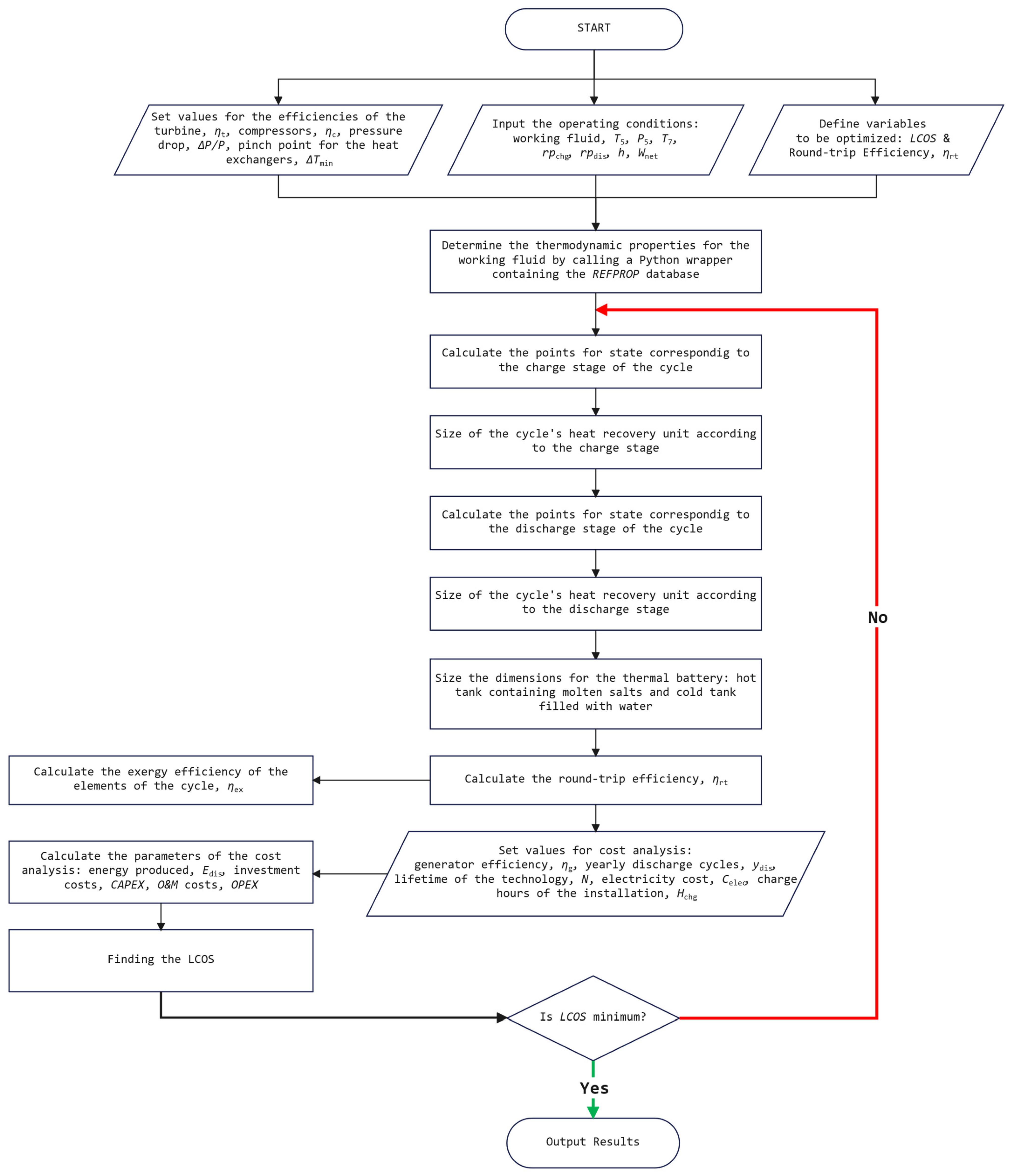
The purpose of this study is to optimize the main design variables of the simple Brayton cycle-based PTES system (SBC-PTES). This study will allow for a comprehensive exploration of the impact of these variables on the system’s thermodynamic behaviour and techno-economic indicators. In order to perform the required simulations, custom code was implemented in MATLAB R2022a. In addition, the thermophysical properties of the working fluid (pure CO2 and binary mixtures) were obtained using REFPROP v10 [39], accessed via a Python 3.9.12 wrapper. A comprehensive overview of the computational procedure is provided in the flowchart presented in Figure 3.

2.7. Benchmarking and Validation

Ensuring the accuracy of the models is of the utmost importance in guaranteeing the reliability of the simulation outcomes and subsequent analyses. The preliminary components of the systems under scrutiny in the present study bear a strong resemblance to those delineated in [8,55]. Accordingly, the models are validated using data from Wang et al. [56]. The results of the validation process are presented in Table 4. This demonstrates a satisfactory alignment between the simulation outcomes and existing data from the literature sources. This finding lends further credence to the reliability of the models developed in this study.

3. Results and Discussion

This section presents an analysis of the results obtained for the SBC-PTES system operating with pure CO2 and with different supercritical binary mixtures of CO2 and hydrocarbons. The study includes an evaluation of the thermodynamic performance during the charge states, the exergy efficiency, the distribution of irreversibilities per component, and the thermo-economics behaviour in terms of LCOS and round-trip efficiency, as well as a sensitivity analysis to variations in the pinch point temperature. Environmental considerations related to the use of CO2 and hydrocarbon mixtures as working fluids are also considered.

3.1. Thermodynamic Performance of the SBC-PTES System with CO2-Hydrocarbon Mixtures

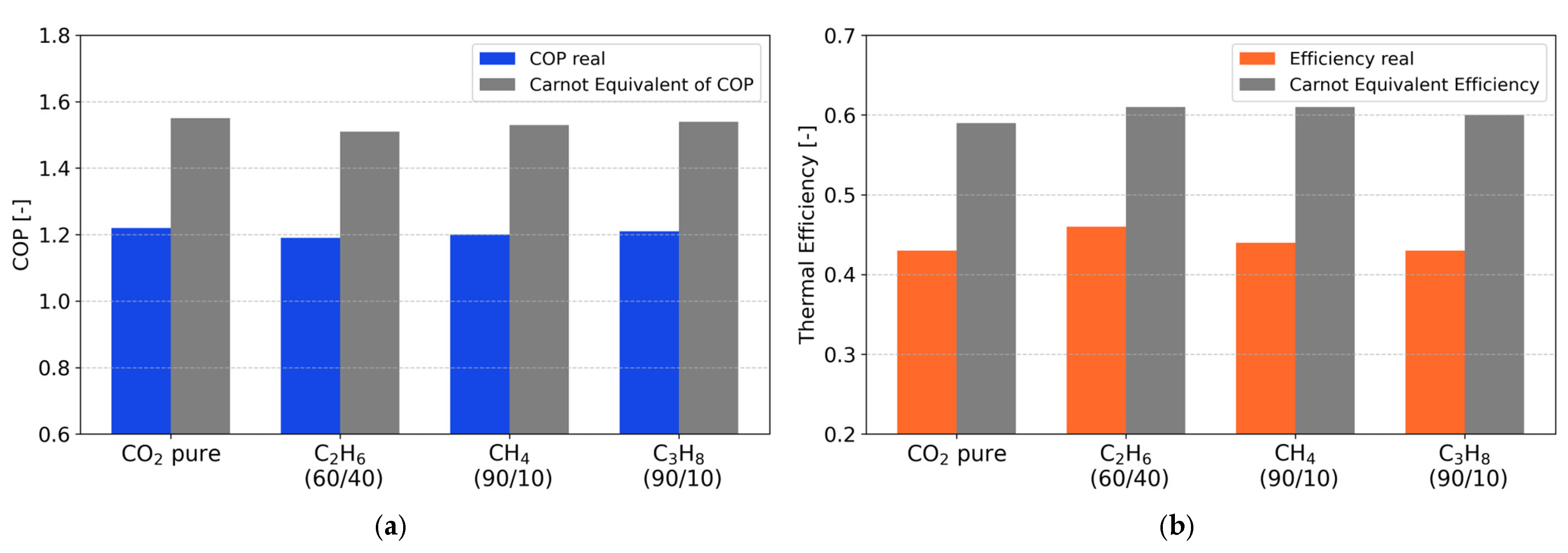
Figure 4 shows the comparison of the performance parameters of the SBC-PTES system during the charge (coefficient of performance, COP) and discharge (thermal efficiency) phases, using as working fluids both pure carbon dioxide and binary mixtures of CO2 with hydrocarbons (C2H6, CH4 and C3H8) in different proportions in a supercritical state. Figure 4a shows that the system exhibits a real COP of between 1.19 and 1.22, depending on the working fluid. The CO2/C3H8 (90/10) mixture showed the best performance, with a COP of approximately 1.21, followed by the CO2/CH4 (90/10) mixture. Pure CO2 also maintains competitive performance, with a COP of 1.22. On the other hand, the mixture with ethane (CO2/C2H6, 60/40) presented the lowest real COP value (1.19), attributable to the higher fluid density and the thermophysical behaviour during the compression process.
In all cases, the actual COP values are approximately 20–22% lower than the equivalent Carnot COP, suggesting that internal system losses in isentropic compression processes remain a significant limiting factor, although hydrocarbon mixtures allow the system to approach the ideal limit.
Figure 4b shows the actual thermal efficiency achieved by the system during discharge mode. The CO2/C2H6 mixture reported the highest actual thermal efficiency value (0.46), surpassing pure CO2 (0.43), while the mixtures with methane and propane (90/10) showed similar values (0.44 and 0.43), respectively. This behaviour is associated with the combined effect of the specific heat capacity of the fluid and the effective pressure ratio reached during expansion. The equivalent Carnot efficiency for all working fluids ranged from 0.59 to 0.61, implying that the system operates within a range of 70 to 75% of the theoretical maximum possible.
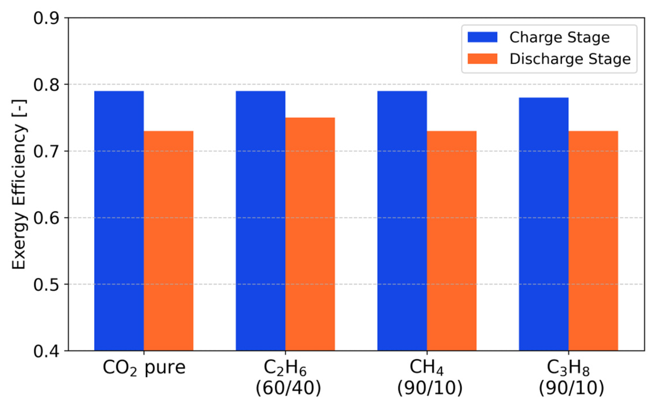
Figure 5 presents a comparison of the exergy efficiency during the charging and discharging stages of the SBC-PTES system for the four working fluids. In all cases, the exergy efficiency is higher during the charging stage due to the lower number of irreversibilities associated with this phase of the process. Among the mixtures studied, the system that works with C2H6 as the working fluid maintains the highest exergetic efficiency in discharge state (0.75), surpassing even pure CO2 (0.73), which suggests a greater adaptability of ethane to controlled expansion conditions in the electricity generation stage. The results shown in Figure 1 and Figure 2 indicate that, while pure CO2 remains competitive as a working fluid in terms of overall efficiency, hydrocarbon mixtures, especially those with ethane, offer a viable alternative that deserves attention in scenarios where the objective is to optimize both the storage and energy conversion systems of the SBC-PTES.
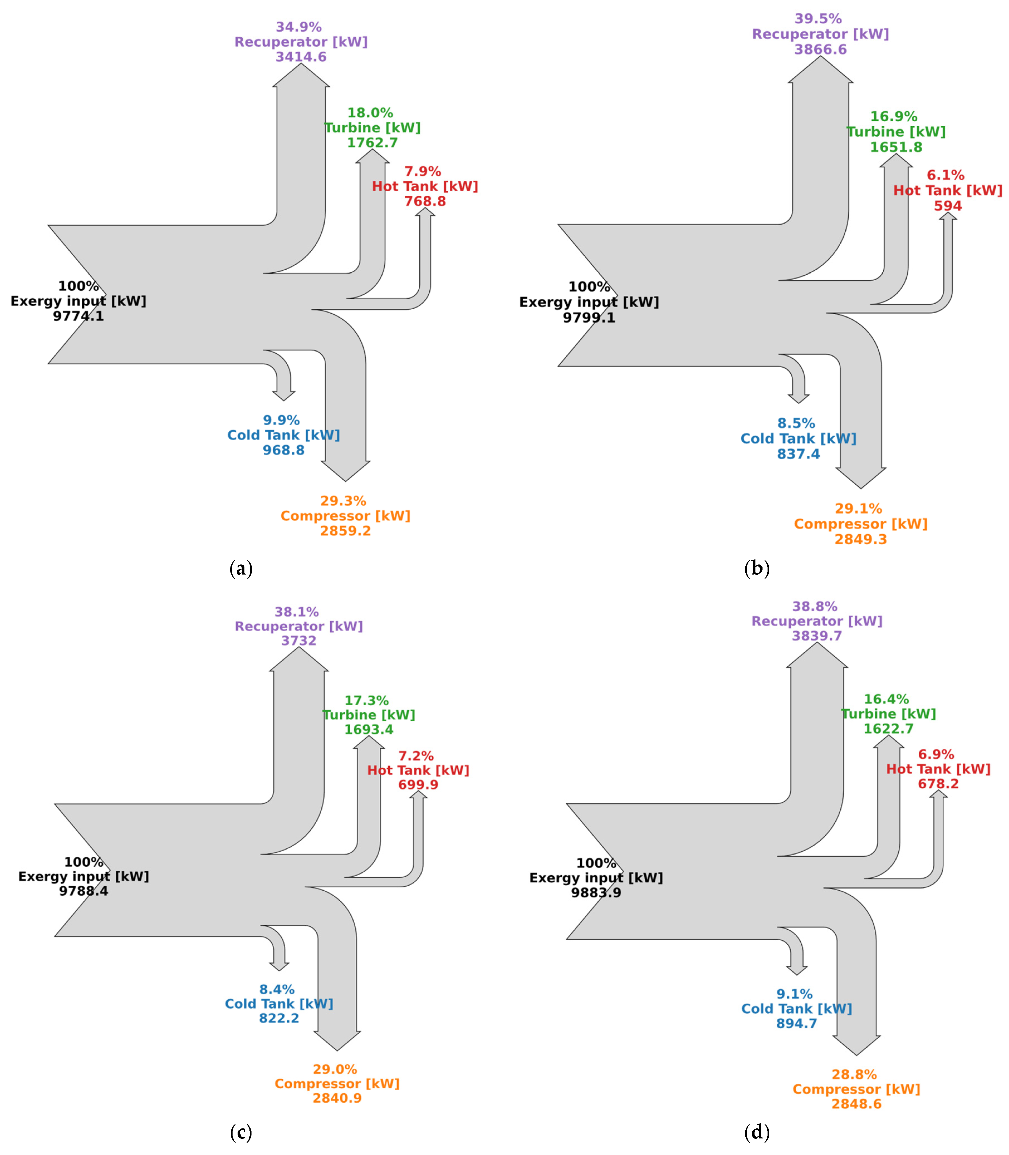
Figure 6 presents a breakdown of each exergy destruction component for the SBC-PTES system during the charging stage. In all cases, the heat recuperator was the component with the greatest exergy destruction, accounting for between 34.9% and 39.5% of the total exergy. This trend is consistent with the irreversible nature of heat transfer processes with a finite temperature difference. The second largest contributor was the compressor, with values between 28.8% and 29.3%, reflecting the losses associated with non-ideal adiabatic compression and its impact on the overall cycle efficiency.
Among the mixtures evaluated, the system using CO2/C2H6 showed the greatest exergy destruction in the recuperator (39.5%) and the least in the turbine (6.1%), suggesting greater thermodynamic compatibility between this fluid and the cycle architecture. Conversely, the CO2/CH4 mixture showed a level of exergetic destruction (17.3%) and a higher exergetic destruction in the hot tank (7.2%), possibly attributed to the less favourable thermal properties of methane.
These results clearly identify critical points of irreversibility within the system, prioritizing the optimization of the recuperator and compressor design and operation to improve overall performance. Furthermore, they reinforce the importance of selecting the working fluid, as it directly influences the exergy destruction pattern of each component.
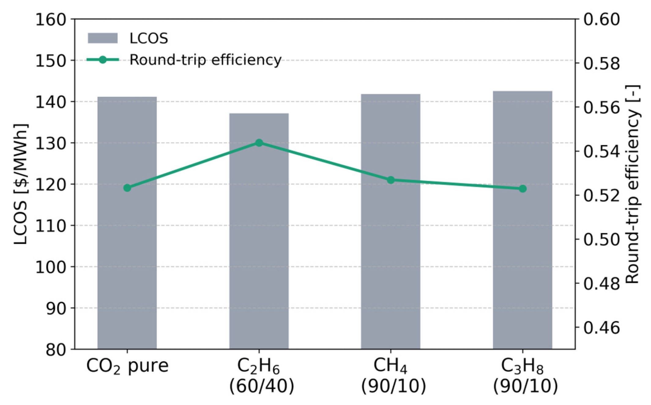
Figure 7 shows the comparison between the Levelized Storage Cost (LCOS) and the round-trip efficiency (RTE) for the different working mixtures evaluated in the SBC-PTES system. The analysis reveals a clear sensitivity of both indicators to the type of fluid, highlighting the significant thermo-economic trade-offs when selecting hydrocarbon mixtures. Pure CO2 base fluid has an LCOS of approximately 141.1 $/MWh, with a round-trip efficiency of 52.33%. However, by incorporating ethane in a mole fraction (60/40), the system achieves the highest round-trip efficiency (54.38%), accompanied by a significant reduction in LCOS to 137.1 $/MWh, representing a performance improvement of around 2% and a cost improvement of 3% compared to pure CO2. This behaviour suggests that the CO2/C2H6 mixture allows for more efficient use of sensible heat and less irreversibility in the charging/discharging processes. Conversely, CO2/CH4 mixtures with a mole fraction of 90/10 show a slight increase in round-trip efficiency (52.69%), with an increase in the LCOS to 147.1 $/MWh. Meanwhile, the CO2/C3H8 mixture with a mole fraction of 90/10 shows a slight decrease in round-trip efficiency (52.29%), with an increase in the LCOS to approximately 142.5 $/MWh. These results indicate that, despite maintaining good thermodynamic properties, the inclusion of methane or propane does not offer substantial economic or operational benefits in the SBC-PTES system.
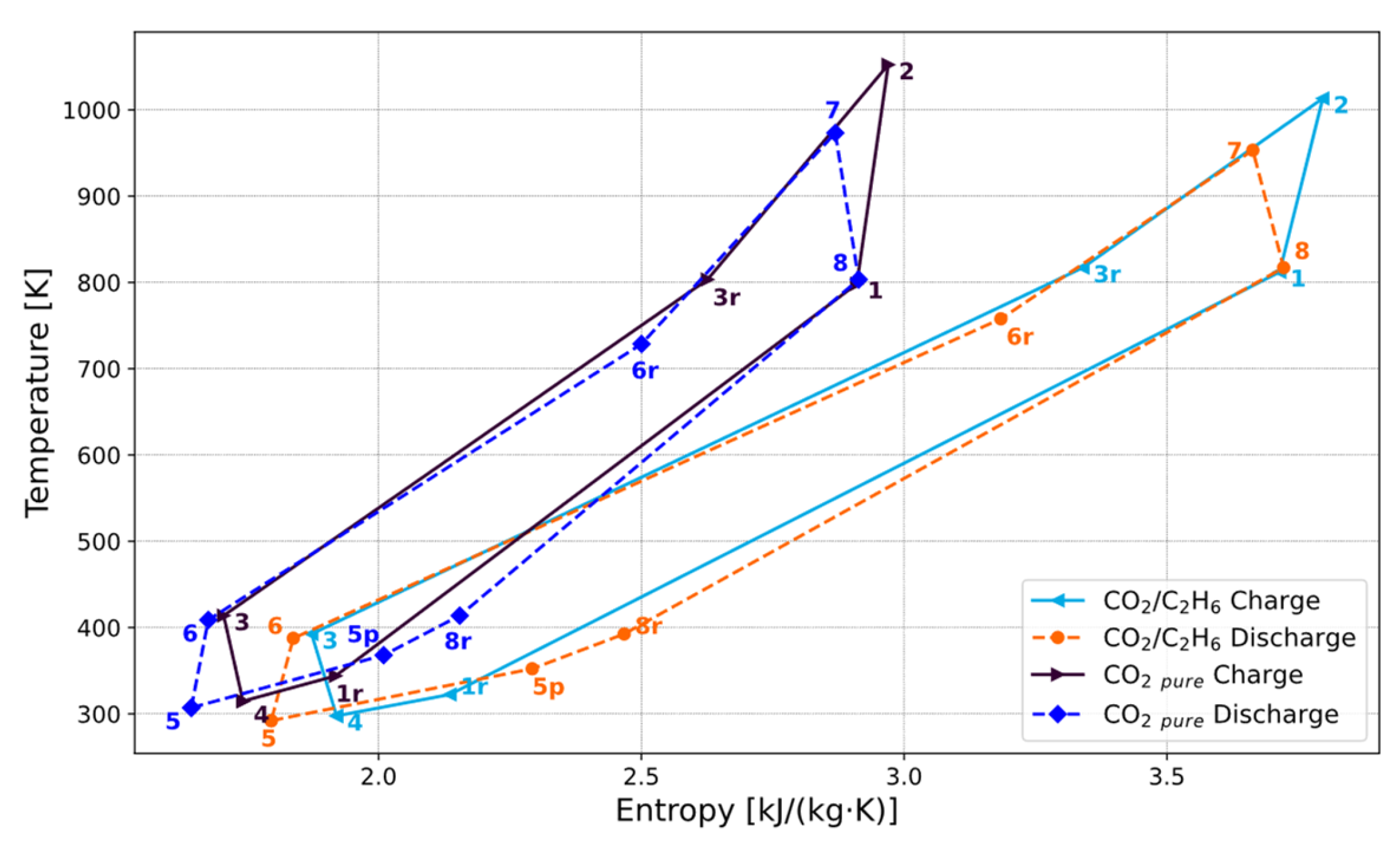
Figure 8 shows the T-s diagram of the charging and discharging stages for pure CO2 and the CO2/C2H6 mixture, where differences in the PTES system morphology can be observed, explaining the better performance of the mixture. In particular, the CO2/C2H6 mixture exhibits a more favourable slope in the compression and expansion processes, which reduces irreversibilities in the heat exchangers. Furthermore, improved thermal adaptation is observed in the heat exchangers, with smaller temperature differences during the exchange processes, which increases internal heat recovery within the system. As a result, the mixture reduces overall entropy generation and improves the utilization of stored energy, leading to greater round-trip efficiency of the system compared to pure CO2.
Compared to previous studies based on mixtures with noble gases (CO2/Kr, CO2/Xe) [8], the use of CO2/C2H6 mixtures shows a more favourable performance under equivalent conditions. For a power output of 50 MW and turbomachine efficiencies of 0.80/0.85, the mixture with Kr exhibits an LCOS of 125.8 $/MWh and an RTE of 0.535, while the mixture with C2H6 achieves an LCOS of 120.7 $/MWh and an RTE of 0.601, demonstrating a simultaneous improvement in both cost and system efficiency.
Furthermore, C2H6 offers a significant advantage over Kr due to its greater availability and lower cost, as it is a hydrocarbon widely accessible on an industrial scale. This aspect reinforces the technical and economic viability of CO2 and hydrocarbon mixtures as a competitive alternative in PTES systems.

3.2. Pinch Point Sensitivity Analysis

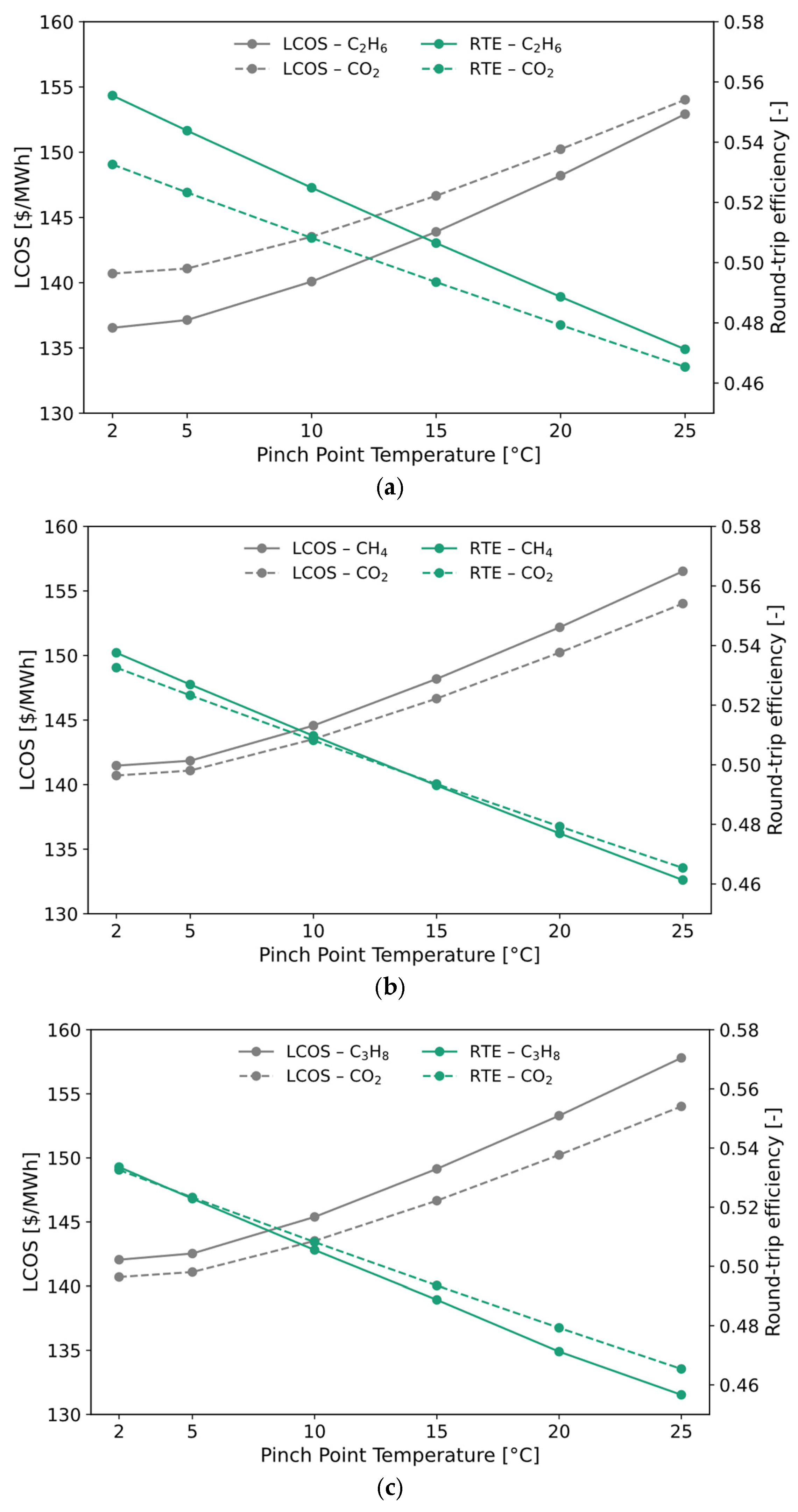
Figure 9 presents the sensitivity of the levelized storage cost and the round-trip efficiency of the SBC-PTES system as a function of the point temperature, comparing the performance of pure CO2 against the mixtures CO2/C2H6, CO2/CH4 and CO2/C3H8.
In all cases, an inverse relationship is observed between the pinch point temperature and the round-trip efficiency. As the pinch point temperature increases from 2 °C to 25 °C, the RTE of the CO2/C2H6 mixture decreases from 55.55 to 47.12 (∆RTE ≈ 8.4%), while the RTE of pure CO2 decreases from 53.26 to 46.54 (∆RTE ≈ 6.7%), see Figure 9a. This greater thermal sensitivity of the mixture indicates greater susceptibility to thermal irreversibilities when the temperature differential across the heat recuperators increases.
In contrast, the LCOS shows a relationship with the increase in the pinch point temperature. In the case of the CO2/C2H6 mixture, the LCOS increases from 136.5 to 152.9 $/MWh (∆LCOS ≈ 12%), while for pure CO2, the values increase from 140.7 to 154.0 $/MWh (∆LCOS ≈ 9.5%). This trend confirms that reducing the efficiency of heat recuperators decreases the overall efficiency of the system and increases the cost of energy storage.
Figure 9b shows a similar trend; however, when approaching temperatures between 2 °C and 10 °C, the mixture with CH4 exhibits a lower LCOS and higher RTE compared to pure CO2. Nevertheless, this advantage diminishes as the pinch point temperature increases, suggesting that the use of mixtures with hydrocarbons is more favourable in designs that prioritize high heat recovery using heat exchangers with narrow temperature margins.
As in the previous cases, a lower pinch point value significantly increases system efficiency and reduces the LCOS. However, the CO2/C3H8 mixture exhibits greater sensitivity to increases in the pinch point temperature compared to pure CO2, with a more pronounced loss of RTE, see Figure 9c. This suggests that, although this mixture can operate with high efficiency under optimal thermal design conditions, its performance is more severely affected under thermal constraints, compromising its economic competitiveness compared to the other fluids studied.

3.3. Environmental Considerations of CO2-Hydrocarbon Mixtures in SBC-PTES Systems

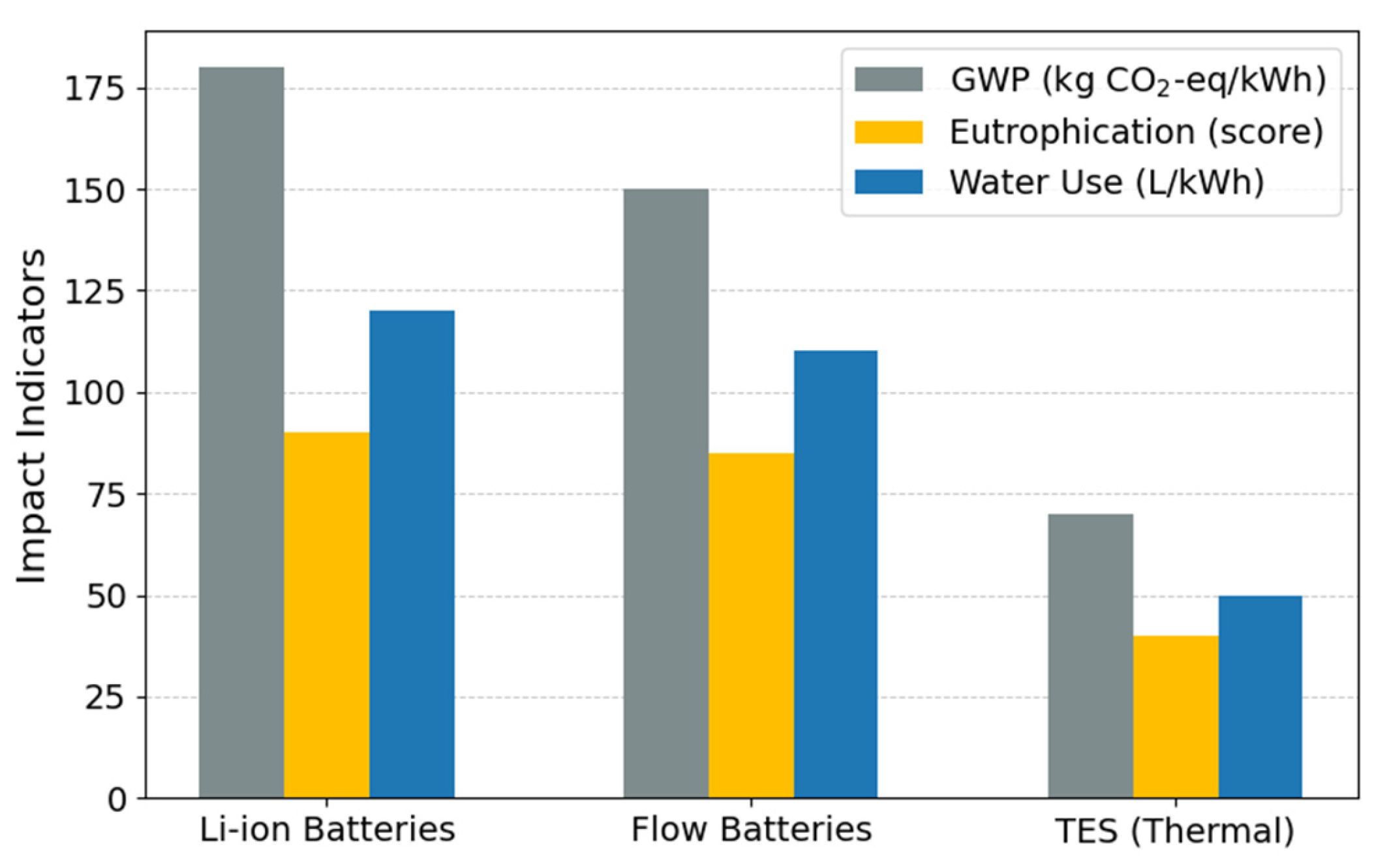
The utilization of hydrocarbons as additives in CO2 mixtures has been demonstrated to enhance thermodynamic and economic performance, while concurrently ensuring environmental acceptability. Compared to fluorinated refrigerants, these compounds have moderate global warming potential (GWP) values: Methane (CH4) ≈ 27.2, Ethane (C2H6) ≈ 12.4, and Propane (C3H8) ≈ 4.3 [55]. In closed SBC-PTES systems, direct emissions can be minimized through airtight designs and maintenance protocols, substantially reducing their climate impact compared to other high-GWP industrial refrigerants. Therefore, these blends can represent a viable alternative from a sustainability perspective, combining energy efficiency with a smaller direct climate footprint, in line with the principles of energy transition and climate change mitigation. Furthermore, SBC-PTES systems that use hydrocarbons as CO2 additives as working fluids offer a more environmentally sustainable alternative to electrochemical technologies, such as lithium-ion or redox flow batteries. By not requiring critical metals like lithium, cobalt, or nickel, they eliminate the ecological and social impacts associated with their extraction, thus reducing dependence on geopolitically sensitive resources.
Life cycle assessment (LCA) studies have identified that battery-based technologies, especially lithium-ion batteries, have significant environmental impacts associated with the extraction of critical metals and intensive manufacturing stages [57,58,59]. In contrast, thermal storage systems tend to have lower overall impacts in categories such as global warming potential, eutrophication, and water consumption, primarily because they avoid the use of critical materials and intensive manufacturing processes. These environmental indicators, including eutrophication potential, are based on LCA studies published in the literature [59,60], which employ standardized methodologies such as ReCiPe and CML for benchmarking energy storage technologies (see Figure 10). This comparison is interpreted as a qualitative and comparative evaluation between energy storage technologies, whose objective is to contextualize the environmental potential of PTES systems.

4. Conclusions

Comparative analysis of the SBC-PTES system using pure CO2 and binary mixtures with hydrocarbons (C2H6, CH4 and C3H8) as working fluids has revealed that the thermo-economic performance of the system is influenced by the fluid composition and the thermal operating conditions.
The combined analysis of COP and thermal efficiency suggests that blends with CH4 and C2H6 offer a favourable compromise between charging and discharging efficiency, allowing for a more balanced system performance. This is especially relevant for stationary applications with cyclic operating regimes. In general, while the CO2/C2H6 mixture exhibits higher round-trip efficiency at low pressure point temperatures, its performance degrades more rapidly under thermally irreversible conditions. This improvement occurs even with a slightly lower turbine inlet temperature (TIT) compared to pure CO2 and the other mixtures (see Table 3), suggesting that the higher specific heat and lower viscosity of the mixture allow for better energy recovery without compromising the performance of the SBC-PTES system. Therefore, proper selection of the thermal approach temperature is crucial for optimizing the balance between thermodynamic performance and economic viability, especially when using binary mixtures as the working fluid. From an economic perspective, the lowest LCOS was obtained for the CO2/C2H6 mixture, reaching 137.1 $/MWh, while configurations with CH4 and C3H8 have higher levelized costs of storage due to their lower overall thermal efficiency, see Table 5.
Taken together, these findings demonstrate the importance of thermal design and working fluid selection in SBC-PTES systems, suggesting that specific blends of CO2 with low viscosity, high specific heat hydrocarbons can offer a competitive balance between energy performance and economic viability, especially when operating with a low pinch point and optimizing heat recovery.
Regarding limitations, the analysis developed is based on a thermodynamic and techno-economic approach under idealized conditions. Therefore, transient dynamic phenomena and the experimental validation of the working fluid properties have not been considered. Furthermore, the behaviour of materials in contact with CO2 mixtures under supercritical conditions has not been evaluated, an aspect that can significantly influence the design, performance, and service life of turbomachines.
In this context, the following future lines of research are proposed: (i) the development and analysis of more complex dynamic cycles applied to PTES systems, (ii) the experimental validation of the thermophysical properties of CO2 mixtures as working fluids, and (iii) the study of the impact of using supercritical CO2 on the materials employed in turbomachine design. These lines of research will allow progress toward a more comprehensive and realistic evaluation of the performance of this technology.

Author Contributions

Conceptualization, P.T.-E. and R.V.-C.; methodology, P.T.-E. and R.V.-C.; software, R.V.-C.; validation, P.T.-E., R.V.-C. and L.G.-P.; formal analysis, P.T.-E. and R.V.-C.; investigation, P.T.-E., R.V.-C. and L.G.-P.; resources, P.T.-E., R.V.-C. and L.G.-P.; data curation, P.T.-E., R.V.-C., L.C.-E. and L.B.-C.; writing—original draft preparation, P.T.-E., R.V.-C. and L.G.-P.; writing—review and editing, P.T.-E., R.V.-C., L.G.-P. and L.B.-C.; visualization, P.T.-E., L.C.-E., L.G.-P. and L.B.-C.; supervision, P.T.-E. and L.C.-E.; project administration, P.T.-E. and R.V.-C. All authors have read and agreed to the published version of the manuscript.

Funding

This work was supported by InvestigaUTN-2025-1504 project, receiving funding from Universidad Técnica del Norte.

Institutional Review Board Statement

Not applicable.

Informed Consent Statement

Not applicable.

Data Availability Statement

The raw data supporting the conclusions of this article will be made available by the authors on request.

Acknowledgments

The authors would like to express their profound gratitude to the GIIA, FOCAPRO and GICFOR Research Groups at the Universidad Técnica del Norte for their indispensable contributions to this research.

Conflicts of Interest

The authors declare no conflicts of interest.

Abbreviations

The following abbreviations are used in this manuscript:
CAPEXCapital cost, M$
C I P Compressor inlet pressure, MPa
C I T Compressor inlet temperature, K
C O P Coefficient of performance
C O P E q C a r n o t Equivalent Carnot coefficient of performance
LCOSLevelized cost of storage, $/MWh
OPEXOperational and maintenance cost, M$
PTESPumped thermal energy storage
REFPROPReference fluid properties
RBCRecompression Brayton cycle
s-CO2Supercritical carbon dioxide
S P Scaling parameter
T I T Turbine inlet temperature, K
m s Molten salts
w Water
Greek symbols
γ Split ratio
η c Compressor efficiency
η E q C a r n o t Equivalent Carnot efficiency
η e x Exergetic efficiency
η g Generator efficiency
η r t Round-trip efficiency
η t Turbine efficiency
η t h Thermal efficiency
σ ˙ Entropic generation, W/K
Roman symbols
C Cost, USD
e Specific exergy, J/kg
E ˙ D Exergy destruction rate, kW
f T Temperature correction factor
H Hours of operation of the plant, h
h Specific enthalpy, J/kg
Mass flow rate, kg/s
N Lifetime of technology, years
n Specific year of operation
P Pressure, MPa
Q ˙ Heat, W
r Discount rate
r p Compression ratio
s Specific entropy, J/kg·K
T Temperature, K
V Volume, m3
y Yearly cycles

References

  1. Hao, Y.; Khan, I. Impact of Decarbonization Enablers, Energy Supply between Transition and Disruption, on Renewable Energy Development. Energy 2025, 324, 135863. [Google Scholar] [CrossRef] [Scilit]
  2. Rekioua, D. Energy Storage Systems for Photovoltaic and Wind Systems: A Review. Energies 2023, 16, 3893. [Google Scholar] [CrossRef] [Scilit]
  3. Yang, H.; Du, X. Thermo-Economic Analysis and Multi-Objective Optimization of Pumped Thermal Electricity Storage System with S-CO2 Recompression Brayton Cycle. J. Energy Storage 2025, 124, 116821. [Google Scholar] [CrossRef] [Scilit]
  4. Liu, Z.; Zhang, H.; Jin, X.; Zheng, S.; Li, R.; Guan, H.; Shao, J. Thermal Economy Analysis and Multi-Objective Optimization of a Small CO2 Transcritical Pumped Thermal Electricity Storage System. Energy Convers. Manag. 2023, 293, 117451. [Google Scholar] [CrossRef] [Scilit]
  5. Rabi, A.M.; Radulovic, J.; Buick, J.M. Pumped Thermal Energy Storage Technology (PTES): Review. Thermo 2023, 3, 396–411. [Google Scholar] [CrossRef] [Scilit]
  6. Frate, G.F.; Ferrari, L.; Sdringola, P.; Desideri, U.; Sciacovelli, A. Thermally Integrated Pumped Thermal Energy Storage for Multi-Energy Districts: Integrated Modelling, Assessment and Comparison with Batteries. J. Energy Storage 2023, 61, 106734. [Google Scholar] [CrossRef] [Scilit]
  7. Sun, R.; Zhao, Y.; Liu, M.; Yan, J. Thermodynamic Design and Optimization of Pumped Thermal Electricity Storage Systems Using Supercritical Carbon Dioxide as the Working Fluid. Energy Convers. Manag. 2022, 271, 116322. [Google Scholar] [CrossRef] [Scilit]
  8. Valencia-Chapi, R.; Tafur-Escanta, P.; Muñoz-Antón, J. Exergetic-Cost Analysis of Pumped Thermal Energy Storage (PTES) Systems Using s-CO2 Mixtures as a Working Fluid. J. Energy Storage 2025, 139, 118952. [Google Scholar] [CrossRef] [Scilit]
  9. Cheraghi, R.; Hossein Jahangir, M. Multi-Objective Optimization of a Hybrid Renewable Energy System Supplying a Residential Building Using NSGA-II and MOPSO Algorithms. Energy Convers. Manag. 2023, 294, 117515. [Google Scholar] [CrossRef] [Scilit]
  10. Steinmann, W.D.; Bauer, D.; Jockenhöfer, H.; Johnson, M. Pumped Thermal Energy Storage (PTES) as Smart Sector-Coupling Technology for Heat and Electricity. Energy 2019, 183, 185–190. [Google Scholar] [CrossRef] [Scilit]
  11. Shalaby, A.B.; Sheikh, N.A.; Ayub, A.; Ahmed, M.; Imran, M.; Shahzad, M.W. Evaluation and Optimization of Supercritical Cycles Using CO2 Based Mixtures as Working Fluids: A Thermodynamic Study. Int. Commun. Heat Mass Transf. 2024, 153, 107370. [Google Scholar] [CrossRef] [Scilit]
  12. Zhao, Y.; Song, J.; Liu, M.; Zhang, K.; Markides, C.N.; Yan, J. Multi-Objective Thermo-Economic Optimisation of Joule-Brayton Pumped Thermal Electricity Storage Systems: Role of Working Fluids and Sensible Heat Storage Materials. Appl. Therm. Eng. 2023, 223, 119972. [Google Scholar] [CrossRef] [Scilit]
  13. Wu, P.; Ma, Y.; Gao, C.; Liu, W.; Shan, J.; Huang, Y. A Review of Research and Development of Supercritical Carbon Dioxide Brayton Cycle Technology in Nuclear Engineering Applications. Nucl. Eng. Des. 2020, 368, 110767. [Google Scholar] [CrossRef] [Scilit]
  14. Wang, K.; Li, M.J.; Guo, J.Q.; Li, P.; Liu, Z.B. A Systematic Comparison of Different S-CO2 Brayton Cycle Layouts Based on Multi-Objective Optimization for Applications in Solar Power Tower Plants. Appl. Energy 2018, 212, 109–121. [Google Scholar] [CrossRef] [Scilit]
  15. Moisseytsev, A.; Sienicki, J.J. Investigation of Alternative Layouts for the Supercritical Carbon Dioxide Brayton Cycle for a Sodium-Cooled Fast Reactor. Nucl. Eng. Des. 2009, 239, 1362–1371. [Google Scholar] [CrossRef] [Scilit]
  16. Morandin, M.; Maréchal, F.; Mercangöz, M.; Buchter, F. Conceptual Design of a Thermo-Electrical Energy Storage System Based on Heat Integration of Thermodynamic Cycles e Part A: Methodology and Base Case. Energy 2012, 45, 375–385. [Google Scholar] [CrossRef] [Scilit]
  17. Valencia-Chapi, R.; Tafur-Escanta, P.; Garzon-Perez, L.; Rodríguez-Martín, J.; Muñoz-Anton, J. Multi-Objective Optimization of the RBC-PTES System Using s-CO2 Mixtures as the Working Fluid. Energy Convers. Manag. X 2026, 29, 101490. [Google Scholar] [CrossRef] [Scilit]
  18. Tafur-Escanta, P.; Cabrera-Ortega, F.; Valencia-Chapi, R.; Garzón-Pérez, L. Parametric Optimization of RBC-PTES System: Impact on Round-Trip Efficiency and LCOS. Energies 2025, 18, 6594. [Google Scholar] [CrossRef] [Scilit]
  19. Linares, J.I.; Montes, M.J.; Cantizano, A.; Sánchez, C. A Novel Supercritical CO2 Recompression Brayton Power Cycle for Power Tower Concentrating Solar Plants. Appl. Energy 2020, 263, 114644. [Google Scholar] [CrossRef] [Scilit]
  20. Coco-Enríquez, L. Nueva Generación de Centrales Termosolares Con Colectores Solares Lineales Acoplados a Ciclos Supercríticos de Potencia. Ph.D. Thesis, Universidad Politécnica de Madrid, Madrid, Spain, 2017. [Google Scholar] [CrossRef] [Scilit]
  21. Tafur-Escanta, P.; López-Paniagua, I.; Muñoz-Antón, J. Thermodynamics Analysis of the Supercritical CO2 Binary Mixtures for Brayton Power Cycles. Energy 2023, 270, 126838. [Google Scholar] [CrossRef] [Scilit]
  22. Yu, A.; Su, W.; Zhao, L.; Lin, X.; Zhou, N. New Knowledge on the Performance of Supercritical Brayton Cycle with CO2-Based Mixtures. Energies 2020, 13, 1741. [Google Scholar] [CrossRef] [Scilit]
  23. Yin, D.; Zhou, Y.; Guo, X. Annals of Nuclear Energy Study on Heat Transfer Characteristics of Supercritical CO2/Propane Mixtures in Vertical Tube. Ann. Nucl. Energy 2024, 196, 110223. [Google Scholar] [CrossRef] [Scilit]
  24. Hawthorne, S.B.; Miller, D.J.; Grabanski, C.B.; Jin, L. Experimental Determinations of Minimum Miscibility Pressures Using Hydrocarbon Gases and CO2 for Crude Oils from the Bakken and Cut Bank Oil Reservoirs. Energy Fuels 2020, 34, 6148–6157. [Google Scholar] [CrossRef] [Scilit]
  25. Steinmann, W. Thermo-Mechanical Concepts for Bulk Energy Storage. Renew. Sustain. Energy Rev. 2017, 75, 205–219. [Google Scholar] [CrossRef] [Scilit]
  26. Olympios, A.V.; Mctigue, J.D.; Farres-antunez, P.; Tafone, A. Progress and Prospects of Thermo-Mechanical Energy Storage—A Critical Review Progress in Energy Progress and Prospects of Thermo-Mechanical Energy Storage—A Critical Review. Prog. Energy 2021, 3, 022001. [Google Scholar] [CrossRef] [Scilit]
  27. Benato, A.; Stoppato, A. Pumped Thermal Electricity Storage: A Technology Overview. Therm. Sci. Eng. Prog. 2018, 6, 301–315. [Google Scholar] [CrossRef] [Scilit]
  28. Desrues, T.; Ruer, J.; Marty, P.; Fourmigué, J.F. A Thermal Energy Storage Process for Large Scale Electric Applications. Appl. Therm. Eng. 2010, 30, 425–432. [Google Scholar] [CrossRef] [Scilit]
  29. Howes, B.J. Concept and Development of a Pumped Heat Electricity Storage Device. In Proceedings of the IEEE; IEEE: New York, NY, USA, 2012. [Google Scholar]
  30. Mercangöz, M.; Hemrle, J.; Kaufmann, L.; Graggen, A.Z.; Ohler, C. Electrothermal Energy Storage with Transcritical CO2 Cycles. Energy 2012, 45, 407–415. [Google Scholar] [CrossRef] [Scilit]
  31. Ma, Y.N.; Hu, P.; Jia, C.Q.; Wu, Z.R.; Chen, Q. Thermo-Economic Analysis and Multi-Objective Optimization of Supercritical Brayton Cycles with CO2-Based Mixtures. Appl. Therm. Eng. 2023, 219, 119492. [Google Scholar] [CrossRef] [Scilit]
  32. Valencia-Chapi, R.; Coco-Enríquez, L.; Muñoz-Antón, J. Supercritical CO2 Mixtures for Advanced Brayton Power Cycles in Line-Focusing Solar Power Plants. Appl. Sci. 2020, 10, 55. [Google Scholar] [CrossRef] [Scilit]
  33. Song, J.; Wang, Y.; Wang, J.; Markides, C.N. Optimal Design of Supercritical CO2 (s-CO2) Cycle Systems for Internal Combustion Engine (ICE) Waste-Heat Recovery Considering Heat Source Fluctuations. In Proceedings of the European sCO2 Conference; DuEPublico—Duisburg-Essen Publications Online: Duisburg-Mitte, Germany, 2021; pp. 205–211. [Google Scholar] [CrossRef]
  34. Thada, S.; Pradeep, A.M.; Sridharan, A. Preliminary Aerodynamic Design of a Supercritical Carbon Dioxide Compressor Impeller for Waste Heat Recovery Applications. In Proceedings of the European sCO2 Conference; DuEPublico—Duisburg-Essen Publications Online: Duisburg-Mitte, Germany, 2021; pp. 154–163. [Google Scholar] [CrossRef]
  35. Siddiqui, M.E.; Taimoor, A.A.; Almitani, K.H. Energy and Exergy Analysis of the S-CO2 Brayton Cycle Coupled with Bottoming Cycles. Processes 2018, 6, 153. [Google Scholar] [CrossRef] [Scilit]
  36. Zhang, R.; Su, W.; Lin, X.; Zhou, N.; Zhao, L. Thermodynamic Analysis and Parametric Optimization of a Novel S–CO2 Power Cycle for the Waste Heat Recovery of Internal Combustion Engines. Energy 2020, 209, 118484. [Google Scholar] [CrossRef] [Scilit]
  37. Li, P.; Molina, E.; Wang, K.; Xu, X.; Dehghani, G.; Kohli, A.; Kassaee, M.H.; Jeter, S.M.; Teja, A.S. Thermal and Transport Properties of NaCl-KCl-ZnCl2 Eutectic Salts for New Generation High-Temperature Heat-Transfer Fluids. J. Sol. Energy Eng. Trans. ASME 2016, 138, 054501. [Google Scholar] [CrossRef] [Scilit]
  38. Turchi, C.S.; Vidal, J.; Bauer, M. Molten Salt Power Towers Operating at 600–650 °C: Salt Selection and Cost Benefits. Sol. Energy 2018, 164, 38–46. [Google Scholar] [CrossRef] [Scilit]
  39. Lemmon, E.W.; Huber, M.L.; McLinden, M.O. NIST Standard Reference Database 23: Reference Fluid Thermodynamic and Transport Properties-REFPROP, Version 10.0; National Institute of Standards and Technology: Gaithersburg, MD, USA, 2010.
  40. Çengel, Y.; Boles, M.; Kanoglu, M. Thermodynamics. An Engineering Approach, 10th ed.; McGraw-Hill Education: Columbus, OH, USA, 2023. [Google Scholar]
  41. Winterbone, D.E.; Turan, A. Advanced Thermodynamics for Engineers, 2nd ed.; Elsevier Ltd.: Amsterdam, The Netherlands, 2015. [Google Scholar]
  42. Sharma, O.P.; Kaushik, S.C.; Manjunath, K. Thermodynamic Analysis and Optimization of a Supercritical CO2 Regenerative Recompression Brayton Cycle Coupled with a Marine Gas Turbine for Shipboard Waste Heat Recovery. Therm. Sci. Eng. Prog. 2017, 3, 62–74. [Google Scholar] [CrossRef] [Scilit]
  43. Weiland, N.T.; Lance, B.W.; Pidaparti, S.R. SCO2 Power Cycle Component Cost Correlations from DOE Data Spanning Multiple Scales and Applications. In Proceedings of the ASME Turbo Expo; American Society of Mechanical Engineers (ASME): New York, NY, USA, 2019; Volume 9. [Google Scholar] [CrossRef] [Scilit]
  44. Delise, T.; Tizzoni, A.C.; Menale, C.; Telling, M.T.F.; Bubbico, R.; Crescenzi, T.; Corsaro, N.; Sau, S.; Licoccia, S. Technical and Economic Analysis of a CSP Plant Presenting a Low Freezing Ternary Mixture as Storage and Transfer Fluid. Appl. Energy 2020, 265, 114676. [Google Scholar] [CrossRef] [Scilit]
  45. Smallbone, A.; Jülch, V.; Wardle, R.; Roskilly, A.P. Levelised Cost of Storage for Pumped Heat Energy Storage in Comparison with Other Energy Storage Technologies. Energy Convers. Manag. 2017, 152, 221–228. [Google Scholar] [CrossRef] [Scilit]
  46. Schmidt, O.; Melchior, S.; Hawkes, A.; Staffell, I. Projecting the Future Levelized Cost of Electricity Storage Technologies. Joule 2019, 3, 81–100. [Google Scholar] [CrossRef] [Scilit]
  47. Bodner, J.; Koksharov, J.; Dammel, F.; Stephan, P. Analysis of Low-Temperature Pumped Thermal Energy Storage Systems Based on a Transcritical CO2 Charging Process. Energy Sci. Eng. 2023, 11, 3289–3306. [Google Scholar] [CrossRef] [Scilit]
  48. Tafur-Escanta, P.; Valencia-Chapi, R.; López-Guillem, M.; Olmo, F.-P.; Muñoz-Antón, J. Electrical Energy Storage Using a Supercritical CO2 Heat Pump. Energy Rep. 2022, 8, 502–507. [Google Scholar] [CrossRef] [Scilit]
  49. Zhang, Y.; Yin, S.; Yan, X.; Liu, Z. Performance of a CO2-Based Mixture Cycled Transcritical Pumped Thermal Energy Storage System. Renew. Energy 2025, 238, 121893. [Google Scholar] [CrossRef] [Scilit]
  50. Linares, J.I.; Martín-Colino, A.; Arenas, E.; Montes, M.J.; Cantizano, A.; Pérez-Domínguez, J.R. Carnot Battery Based on Brayton Supercritical CO2 Thermal Machines Using Concentrated Solar Thermal Energy as a Low-Temperature Source. Energies 2023, 16, 3871. [Google Scholar] [CrossRef] [Scilit]
  51. Barberis, S.; Maccarini, S.; Shamsi, S.S.M.; Traverso, A. Untapping Industrial Flexibility via Waste Heat-Driven Pumped Thermal Energy Storage Systems. Energies 2023, 16, 6249. [Google Scholar] [CrossRef] [Scilit]
  52. McTigue, J.D.; Farres-Antunez, P.; Neises, T.; White, A. Supercritical CO2 Heat Pumps and Power Cycles for Concentrating Solar Power. In Proceedings of the 26th SolarPACES Conference, Online, 29 September–2 October 2020. [Google Scholar]
  53. Jülch, V. Comparison of Electricity Storage Options Using Levelized Cost of Storage (LCOS) Method. Appl. Energy 2016, 183, 1594–1606. [Google Scholar] [CrossRef] [Scilit]
  54. Ökten, K.; Kurşun, B. Thermo-Economic Assessment of a Thermally Integrated Pumped Thermal Energy Storage (TI-PTES) System Combined with an Absorption Refrigeration Cycle Driven by Low-Grade Heat Source. J. Energy Storage 2022, 51, 104486. [Google Scholar] [CrossRef] [Scilit]
  55. United Nations. Climate Change 2021: The Physical Science Basis. In The Intergovernmental Panel on Climate Change; Cambridge University Press: Cambridge, UK, 2021. [Google Scholar]
  56. Wang, K.; Shi, X.; He, Q. Thermodynamic Analysis of Novel Carbon Dioxide Pumped-Thermal Energy Storage System. Appl. Therm. Eng. 2024, 255, 123969. [Google Scholar] [CrossRef] [Scilit]
  57. Saha, N.; Pavelkov, D.; Saha, N.; Motiei, M.; Jamatia, T.; Chaudhuri, M.; Ivanichenko, A.; Venher, M.; Hrb, L. Life Cycle Assessment of Lithium-Based Batteries: Review of Sustainability Dimensions. Renew. Sustain. Energy Rev. 2024, 206, 114860. [Google Scholar] [CrossRef] [Scilit]
  58. Stanchev, P.; Hinov, N. Comparative Techno-Economic and Life Cycle Assessment of Stationary Energy Storage Systems: Lithium-Ion, Lead-Acid, and Hydrogen. Batteries 2025, 11, 382. [Google Scholar] [CrossRef] [Scilit]
  59. Hayatina, I.; Auckaili, A.; Mohammed, F. Review on the Life Cycle Assessment of Thermal Energy Storage Used in Building Applications. Energies 2023, 16, 1170. [Google Scholar] [CrossRef] [Scilit]
  60. Tournaviti, M.; Michailidou, A.V.; Savva, C.; Vlachokostas, C. Bridging the Gap between Life Cycle Assessment and Lithium-Ion Batteries for Electrification of Vehicles: A Critical Review towards Unified Frameworks. Future Batter. 2025, 5, 100047. [Google Scholar] [CrossRef] [Scilit]
Figure 1. SBC as PTES system. (a) charging stage and (b) discharging stage [8]. Cold Tank Heat Exchanger: 4-1r (charge); 8r-5p (discharge); Hot Tank Heat Exchanger: 2-3r (charge), 6r-7 (discharge).
Applsci 16 04068 g001aApplsci 16 04068 g001b
Figure 2. Fluids properties. (a) Critical pressure vs. critical temperature. (b) Critical density vs. additive’s mole fraction.
Applsci 16 04068 g002
Figure 3. Code flowchart for the development of optimization.
Applsci 16 04068 g003
Figure 4. Comparison of thermodynamic performance indicators of the SBC-PTES system. (a) Coefficient of performance (COP) and (b) thermal efficiency.
Applsci 16 04068 g004
Figure 5. Exergy efficiency during the charge and discharge state.
Applsci 16 04068 g005
Figure 6. Exergy destruction during charge stage of the SBC-PTES system. (a) CO2 pure, (b) CO2/C2H6, (c) CO2/CH4 and (d) CO2/C3H8.
Applsci 16 04068 g006
Figure 7. Comparison of LCOS and RTE indicators of the SBC-PTES system.
Applsci 16 04068 g007
Figure 8. T-s diagram of the charging and discharging stages for pure CO2 and the CO2/C2H6 mixture.
Applsci 16 04068 g008
Figure 9. Sensitivity of the LCOS and RTE indicators of the SBC-PTES system for different pinch points. (a) C2H6, (b) CH4 and (c) C3H8.
Applsci 16 04068 g009
Figure 10. Environmental comparison of storage technologies: GWP, eutrophication and water use.
Applsci 16 04068 g010
Table 1. TES system design parameters.
ParameterValues Range
HTF typeZnCl2/NaCl/KCl Molten Salt
Salt maximum bulk operating temperature [°C]>1073.15 K
Salt melting or liquidus point [°C]423.15 K
Storage duration [h]11
Hot Tank temperature765.97 → 1012.71 K
Cold Tank Temperature341.34 → 378.92 K
Table 3. Coefficients and parameters for LCOS calculation [8].
ComponentParameterValueUnits
Discount rate [48,53] r 8%
Electricity price [48,54] C e l e 55$/MWh
Generator efficiency [47,48] η g 0.98-
Plant life [48,49] N 30years
Storage time [48,52] H c h g 11h
Yearly discharge cycles [48,49,53] y d i s 3501/year
Table 4. Results of model validation.
ParameterUnitReference [56] This WorkError [%]
C I P d i s MPa1.201.200.00
C I T d i s K5735730.00
r p c h g -7.257.250.00
r p d i s -7.257.250.00
η c %90900.00
η t %92920.00
η r t %62.8363.531.12
Table 5. Multiparameter optimization results of SBC-PTES system to minimize LCOS.
CO2
Pure
CO2/C2H6
(60/40)
CO2/CH4
(90/10)
CO2/C3H8
(90/10)
Units
CIP74598170bar
CIT307.1292.1302.1308.1K
TIT973.2953.2973.2963.2K
r p c h g 4.0545.0843.7034.285-
r p d i s 4.0545.0843.7034.285-
H c h g 11111111h
H d i s 10.110.2110.089.93h
LCOS141.1137.1141.8142.5$/MWh
η r t 52.3354.3852.6952.29%
Disclaimer/Publisher’s Note: The statements, opinions and data contained in all publications are solely those of the individual author(s) and contributor(s) and not of MDPI and/or the editor(s). MDPI and/or the editor(s) disclaim responsibility for any injury to people or property resulting from any ideas, methods, instructions or products referred to in the content.