3. Results and Discussion
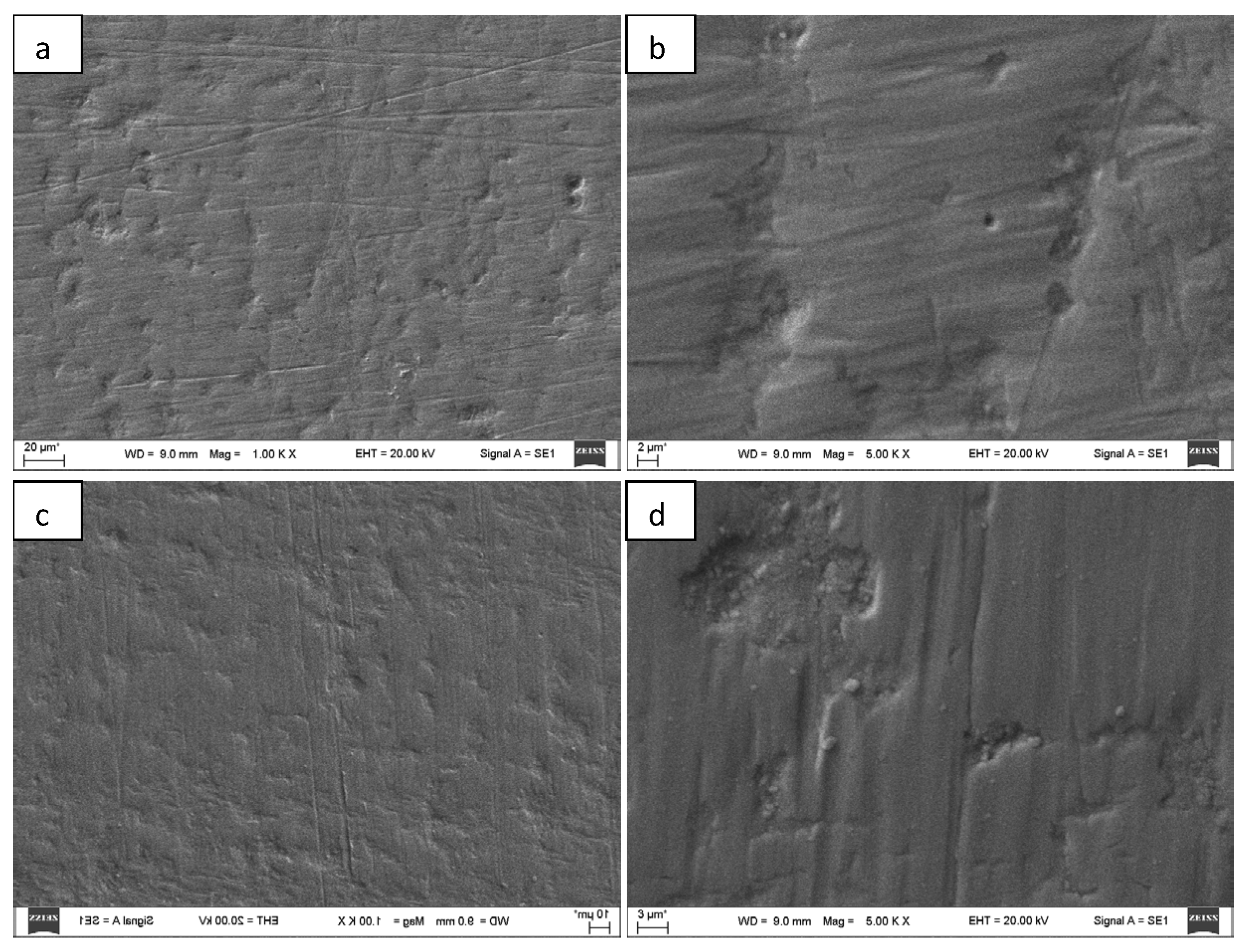
In the context of this study, SEM microscopy images obtained at 2 µm zirconium oxide (ZrO
2) thickness and 1000× and 5000× magnification show that the resulting coating on the stainless-steel substrate has a relatively heterogeneous microstructure (
Figure 2a,b). Fine linear or elongated microrelief elements oriented along the surface are observed over the entire surface, which are visible both at lower (1000×) and higher (5000×) magnification. In addition, very fine micro-indentations are identified in some places. Such surface morphology may be related to the fact that during the formation of the ZrO
2 coating, it partially replicates the microrelief of the stainless-steel substrate, which occurs due to surface structures formed during mechanical processing or polishing.
On the other hand, a similar microstructure can also be formed due to the coating growth mechanism itself during the sputtering process, when particle condensation and surface diffusion lead to the directional formation of structures and the appearance of local irregularities. Such a microrelief structure can affect the surface area of the coating and its interaction with the liquid under study, therefore it is important in assessing the sensitivity of a capacitive sensor and changes in its electrical properties when measuring the concentration of liquid components.
In the context of this study, SEM images obtained at 4 µm ZrO
2 thickness and 1000× and 5000× magnification can be interpreted as showing a more advanced stage of coating formation, when a thicker and more continuous zirconium oxide layer is formed on the stainless-steel substrate (
Figure 2c,d). Compared to the 2 µm coating, a longer deposition time (when a higher thickness is obtained) usually leads to better substrate coverage, a more pronounced formation of a specific coating microstructure and a smaller influence of the substrate relief on the final surface morphology. If linear or elongated irregularities are still visible in the SEM images, this may indicate that the coating partially replicates the topography of the steel surface, but at the same time it is likely that structural elements determined by the growth of the ZrO
2 coating itself become apparent due to the longer deposition. Small surface irregularities, local thickenings or micro-indentations can be attributed to the effects of particle condensation, layer densification and internal stresses during coating formation. Such a more developed microstructure is important for the performance of a capacitive sensor, as it can increase the effective interaction surface with the liquid medium, change the local electric field at the sensor surface and thus affect the sensitivity and response of the sensor when measuring the concentration of liquid components [
1,
2,
3].
In order to avoid damage to the thin film morphology and ensure the formation of a uniform and stable ZrO2 coating, careful control of the deposition parameters is essential. The results of this study indicate that film morphology is strongly influenced by deposition time, plasma stability, and substrate-related factors. In particular, insufficient deposition time leads to incomplete surface coverage and the replication of substrate microrelief, while excessive growth may result in increased surface roughness and internal stresses. These considerations are consistent with the SEM observations obtained in this study, where thinner films (~2 µm) exhibited pronounced substrate-induced morphology, while thicker coatings (~4–6 µm) showed more continuous structures but increased surface roughness and microstructural irregularities. To minimize morphological defects such as micro-cracks, irregular growth structures, or surface inhomogeneities, several strategies can be applied. First, maintaining stable plasma conditions during magnetron sputtering is critical, which can be achieved by using a controlled argon–oxygen gas mixture to prevent discharge instability and arcing effects. Second, optimizing deposition time allows achieving a continuous and sufficiently dense coating without excessive roughness; in this study, a thickness of approximately 4 µm demonstrated a favourable balance between structural integrity and uniformity. Third, proper substrate preparation, including cleaning and surface polishing, reduces the influence of initial surface defects and improves coating adhesion. Additionally, controlling residual stresses in the growing film is important to prevent mechanical degradation of the coating. This can be achieved by adjusting deposition parameters such as pressure, target current, and deposition rate. A moderate deposition rate promotes more uniform film growth and reduces the likelihood of defect formation. Therefore, the combination of optimized deposition conditions and controlled film thickness is a key factor in preventing morphological damage and ensuring reliable performance of ZrO2-coated capacitive sensors.
EDS elemental composition analysis allows us to assess the formation of a zirconium oxide (ZrO
2) coating on a stainless-steel substrate, depending on the duration of magnetron sputtering. At a thickness of 2 µm, the elements C, O, Cr, Fe, Ni and Zr were identified in the spectrum. The largest share of atomic concentrations is oxygen (28.8 at. %), which confirms the formation of an oxide layer on the surface of the coating. However, at the same time, a relatively high concentration of iron (38.4 at. %), as well as chromium (10.6 at. %) and nickel (5 at. %), which are characteristic elements of a stainless-steel substrate, were detected. This indicates that with a shorter deposition time (smaller thickness), the ZrO
2 coating formed is relatively thin; therefore, a significant signal of substrate elements is still recorded during EDS analysis. The zirconium concentration reaches 8.7 at. %, which confirms the formation of a zirconium-containing coating on the surface. Meanwhile, at a 4 µm thick magnetron sputtering time, the elemental composition changes noticeably—the largest share is made up of oxygen (47.5 at. %) and zirconium (22 at. %), which indicates a more developed and thicker zirconium oxide layer. At the same time, the concentrations of substrate elements—iron (12.9 at. %), chromium (4 at. %) and nickel (1.3 at. %)—decrease significantly, which confirms that a longer deposition time (60 min) leads to better substrate coverage and greater coating integrity. In both cases, a small amount of carbon (8.5–12.1 at. %), which is most likely related to hydrocarbons adsorbed on the surface or possible contamination during deposition or measurement, was detected. Such EDS results confirm the successful formation of the ZrO
2 coating and show that with increasing deposition time, the coating thickness and its dominance in the surface elemental composition increase, which is important in assessing the dielectric properties of the coating and its suitability for capacitive sensor applications in liquid concentration measurements [
1,
2,
3,
4].
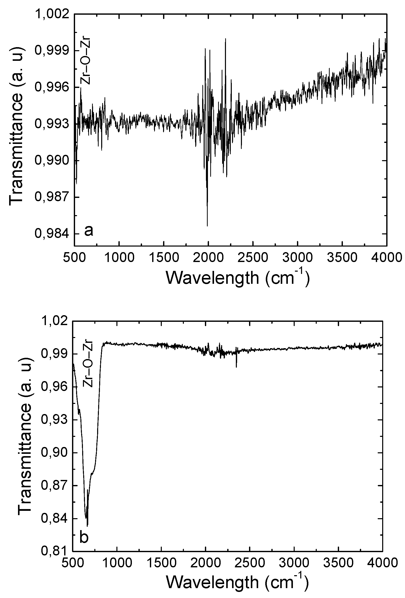
Interpretation of the FTIR spectrum obtained for the ZrO
2 coating deposited under 30 min sputtering conditions (2 µm) shows that the most important absorption bands are concentrated in the low wavenumber region, which is characteristic of metal–oxygen bonds (
Figure 3a). The brighter minima at around 530 and 442 cm
−1 can be attributed to Zr–O and Zr–O–Zr vibrations, respectively, and these results confirm that a zirconium oxide layer has formed on the stainless-steel surface. Additional, weaker bands around 766–862 cm
−1 can be attributed to more complex oxide lattice vibrations or surface structure irregularities formed during the growth of the coating. Meanwhile, weak signals in the higher wavenumber region, including the region around 1700 cm
−1 and broader changes above 3000 cm
−1, are most likely not related to the main ZrO
2 lattice, but to adsorbed moisture, surface hydroxyl groups or environmental impurities, which are often found in the FTIR spectra of thin oxide coatings. Since the bands characteristic of ZrO
2 were identified in the low wavenumber region, it can be stated that the sputtering time of 30 min was sufficient for the formation of the zirconium oxide coating, although the relatively low absorption intensity suggests that the layer is still relatively thin and its formation is not completely completed, which is in good agreement with the SEM and EDS results, which indicate the partial survival of the substrate signal and the still developing microstructure of the coating. The interpretation of the FTIR spectrum obtained for the ZrO
2 coating deposited for 60 min (thickness 4 µm) under sputtering conditions shows a more pronounced formation of the zirconium oxide layer than in the case of shorter sputtering (
Figure 3b). The most important absorption bands are observed in the low wavenumber region, especially around 665 cm
−1, as well as weaker bands around 566, 480 and 457 cm
−1, which can be attributed to the vibrations of the Zr–O and Zr–O–Zr bonds, which are characteristic of the zirconium oxide lattice. The intensity of these bands allows us to state that after 60 min of deposition time, a more developed and thicker ZrO
2 layer has formed, therefore the signal of the oxide coating in the FTIR spectrum becomes clearer and dominant. In the higher wavenumber region, weak changes around 1654 cm
−1 and very slight signals in the broad region of 3700–3900 cm
−1 are most likely associated with adsorbed moisture and surface hydroxyl groups, which are characteristic of oxide coating surfaces after contact with the environment. Also, a small band around 2349 cm
−1 may be related to atmospheric CO
2 adsorption during the measurement, therefore it should not be considered a main characteristic of the coating structure. In conclusion, it can be stated that the sputtering time of 60 min (thickness 4 µm) created more favorable conditions for the formation of a more pronounced zirconium oxide coating, and the FTIR data are in good agreement with the SEM and EDS results, indicating a thicker, more continuous layer with a higher zirconium and oxygen content, which is favorable for the stability of the dielectric properties of the capacitive sensor and sensitivity in the concentration measurements of liquid components.
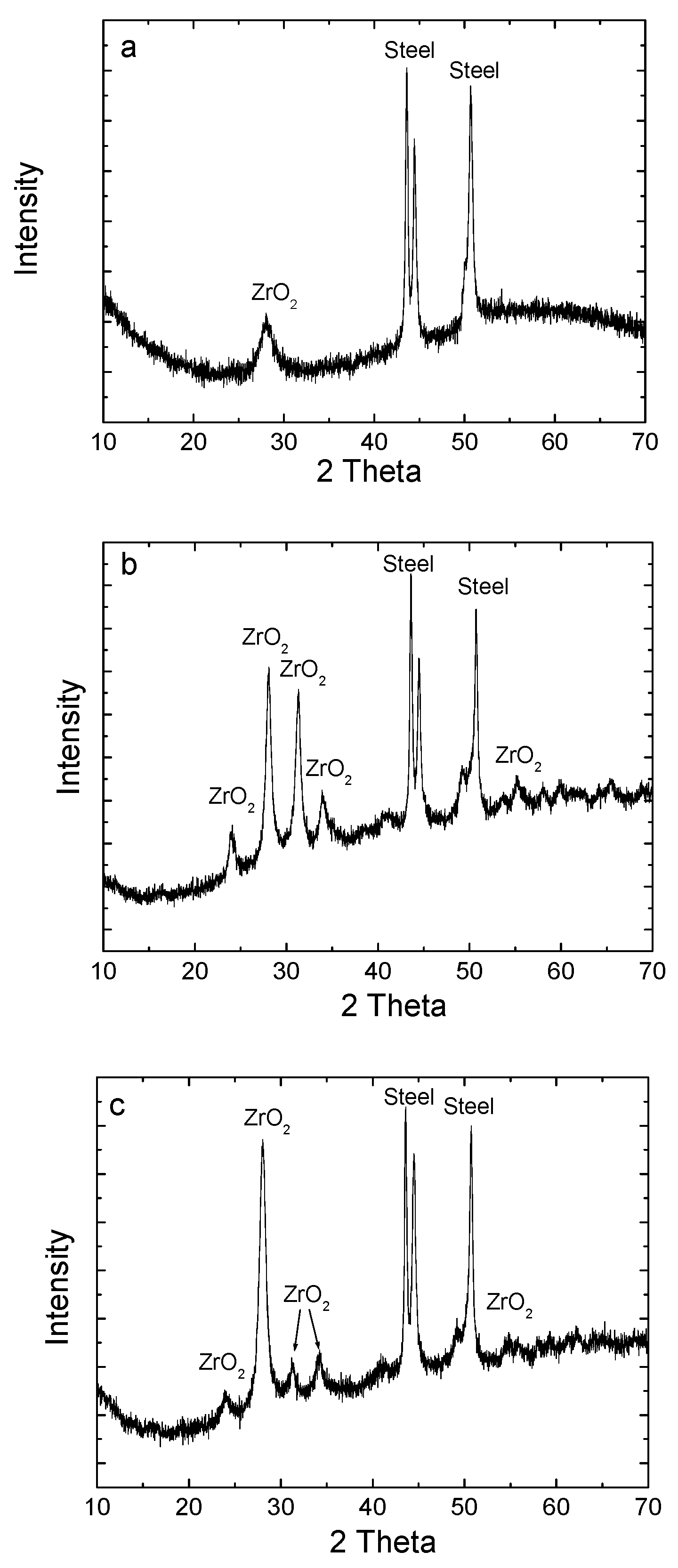
XRD analysis shows that at a zirconia coating thickness of 2 µm, one main peak characteristic of the coating appears in the diffractogram at approximately 28° (2θ), while the remaining intense peaks are mainly attributed to the stainless-steel substrate, which allows us to state that the formed ZrO
2 layer is still relatively thin and X-ray radiation easily reaches the substrate (
Figure 4a). The peak at ~28° is characteristic of the reflex of the monoclinic zirconia phase and is usually associated with the m-ZrO
2 (−111) plane, therefore it can be stated that at a thickness of 2 µm, a crystalline monoclinic ZrO
2 phase with the predominant orientation of this plane is already forming in the coating. Since other clear ZrO
2 peaks are almost invisible or overlap with the substrate signals, it is likely that the crystallinity of the coating is not yet very high, and the amount of crystallites and the layer thickness are not sufficient for the formation of a brighter diffraction pattern of the entire ZrO
2. This result indicates the initial stage of the formation of a crystalline coating, when zirconium oxide is no longer completely amorphous, but its diffraction response is still weak due to the small layer thickness and significant substrate influence. This interpretation is in good agreement with the SEM, EDS and FTIR results, which show that after 30 min of deposition (2 µm layer thickness), a zirconium oxide layer is formed, but it is not yet completely uniform and thick enough, so the substrate signal remains bright, which is important for assessing the structural and dielectric properties of the coating for the application of a capacitive sensor in liquid component concentration measurements [
2,
3,
4,
5].
In
Figure 4b, XRD analysis shows that at a zirconia coating thickness of 4 µm, the peaks of the ZrO
2 crystalline phase at approximately 24°, 28°, 32°, 34° and 55° (2θ) become more clearly visible in the diffractogram, which indicates a more formed and higher crystallinity layer than after 30 min sputtering (with a thickness of 2 µm). The peak at ~24° can be associated with the m-ZrO
2 (−110) plane of the monoclinic zirconia phase, at ~28°—with m-ZrO
2 (−111), at ~32°—with m-ZrO
2 (111), and at ~34°—with m-ZrO
2 (200) plane; the additional peak at ~55° is also characteristic of the monoclinic phase reflections and can be associated with the diffraction of higher-order m-ZrO
2 planes. Such occurrence of several characteristic peaks allows us to state that the crystalline monoclinic zirconia phase prevails in the 4 µm coating, and the most intense reflex at ~28° indicates a preferential orientation along the m-ZrO
2 (−111) plane. Since some of the ZrO
2 peaks overlap with the peaks of the stainless-steel substrate, the influence of the substrate on the diffractogram remains significant, but, compared to the case of 2 µm sputtering, the higher number of identifiable ZrO
2 reflexes indicates a thicker layer and more advanced formation of the crystalline structure. Such a result allows us to conclude that a longer sputtering time promotes not only an increase in the thickness of the coating, but also an increase in its crystallinity, resulting in a more structured ZrO
2 layer, which should be more favorable for stable dielectric properties and better response of the capacitive sensor when measuring the concentration of liquid components. XRD analysis shows that at a zirconia coating thickness of 6 µm, the same ZrO
2 characteristic reflections at approximately 24°, 28°, 32°, 34° and 55° (2θ) remain in the diffractogram (
Figure 4c), and their position and overall diffraction pattern are very similar to the 60 min sputtering case. These peaks can be assigned to the monoclinic zirconia phase: at ~24°—m-ZrO
2 (−110), at ~28°—m-ZrO
2 (−111), at ~32°—m-ZrO
2 (111), at ~34°—m-ZrO
2 (200), and the peak at ~55° also corresponds to the higher-order diffraction of the monoclinic phase. The most intense reflection at ~28° allows us to conclude about the prevailing preferential orientation along the m-ZrO
2 (−111) plane. Since some of the peaks characteristic of zirconium oxide overlap with the reflections of the stainless steel substrate, the influence of the substrate on the diffractogram still remains, but several clearly identifiable ZrO
2 peaks confirm that the layer formed after 90 min (6 µm) sputtering is crystalline and sufficiently developed. The fact that the diffraction pattern is very similar to the 4 µm case indicates that with further increasing coating thickness, no significant changes in the phase composition occur, and the same monoclinic ZrO
2 phase continues to dominate in the coating. Therefore, it can be stated that in the interval between 4 and 6 µm, the crystalline structure of the coating is essentially stabilized, and the main changes are most likely more related to the increase in layer thickness or a slight improvement in crystallinity, but not to the formation of new phases. This result is important in the research context, as it shows that increasing thickness allows maintaining a structurally stable zirconia coating, which is favorable for repeatable dielectric properties and reliable capacitive sensor performance when measuring the concentration of liquid components (e.g., salt).
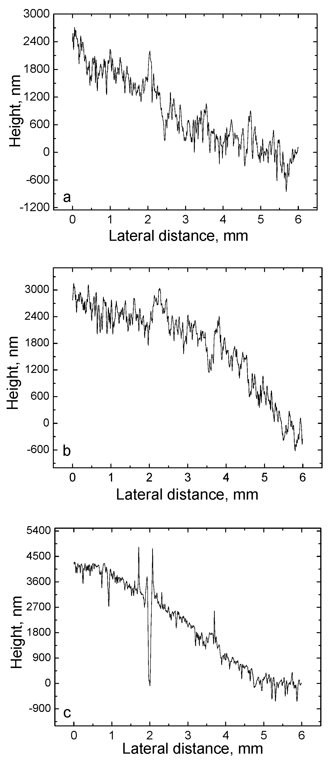
The results of profilometric measurements show that with a 30 min ZrO
2 sputtering time, a relatively thin, but already clearly measurable zirconium oxide layer was formed on the stainless-steel substrate, the step height of which according to the profile curve is approximately in the order of several micrometers, about 2 µm (
Figure 5a). The height difference between the coated and uncoated areas visible in the profilogram confirms the successful deposition of the coating, while the observed profile fluctuations and irregularities indicate that the surface is not ideally smooth. Such a shape can be associated both with the influence of the microrelief of the initial stainless-steel substrate and with the growth characteristics of the ZrO
2 coating itself during sputtering, when the layer is formed by uneven densification and repeats part of the substrate topography. The relatively small coating thickness of 2 µm is in good agreement with SEM, EDS, FTIR and XRD results, which show that after 30 min of sputtering, the zirconium oxide layer has already formed, but still remains quite thin, therefore the influence of the substrate on both the surface morphology and the elemental and structural characteristics is still noticeable. Such a coating state is important for the operation of a capacitive sensor, because even a small but already formed oxide layer can change the dielectric properties of the electrode surface and affect the sensitivity of the sensor when measuring the concentration of liquid components [
1,
3,
11].
The profilometric measurement results show that at a ZrO
2 sputtering time of 60 min, a clearly measurable zirconium oxide layer was formed on the stainless-steel substrate, the thickness of which, according to the difference in the height of the profilogram, is approximately 4 µm (
Figure 5b). The sharp transition between the coated and uncoated areas visible in the profile confirms the successful deposition of the coating, and the rather large step height indicates that the longer sputtering time led to more intensive layer growth and better substrate coverage. At the same time, the height fluctuations and surface irregularities observed in the profilogram allow us to state that the coating is not ideally smooth, and its relief is formed by both the initial topography of the stainless-steel surface and the growth characteristics of the ZrO
2 coating itself during the sputtering process. Such a thicker coating reduces the influence of the substrate on the surface properties, therefore this result is in good agreement with the SEM, EDS and XRD data, which in the case of 4 µm show a more developed ZrO
2 coating with a higher zirconium and oxygen content and a clearer crystalline structure. In the context of the publication, this allows us to state that a 60 min sputtering time is sufficient to form a relatively thick and continuous zirconium oxide layer, which should be favorable for more stable dielectric properties and more efficient operation of the capacitive sensor when measuring the concentration of liquid components. The results of the profilometric measurement show that a clearly measurable and sufficiently thick zirconium oxide layer was formed on the stainless-steel substrate with a 90 min ZrO
2 sputtering time. According to the difference in the height of the presented profile, the thickness of the coating can be estimated as approximately 6 µm (
Figure 5c). The sharp transition between the coated and uncoated areas visible in the profilogram confirms the successful deposition of the coating, and the general nature of the profile indicates that the layer becomes more developed with increasing sputtering time. At the same time, quite pronounced height fluctuations and local irregularities observed in the curve allow us to state that the surface is not smooth, and its relief is determined by both the initial topography of the stainless-steel substrate and the growth mechanism of the ZrO
2 coating itself during deposition. Such morphology is characteristic of thicker oxide coatings, when the layer growth is uneven, and a more pronounced microrelief is formed on the surface. The sputtering time of 90 min allows the formation of a well-developed ZrO
2 layer, which should more effectively insulate the substrate, ensure more stable dielectric properties and be favourable for the operation of the capacitive sensor when measuring the concentration of liquid components.
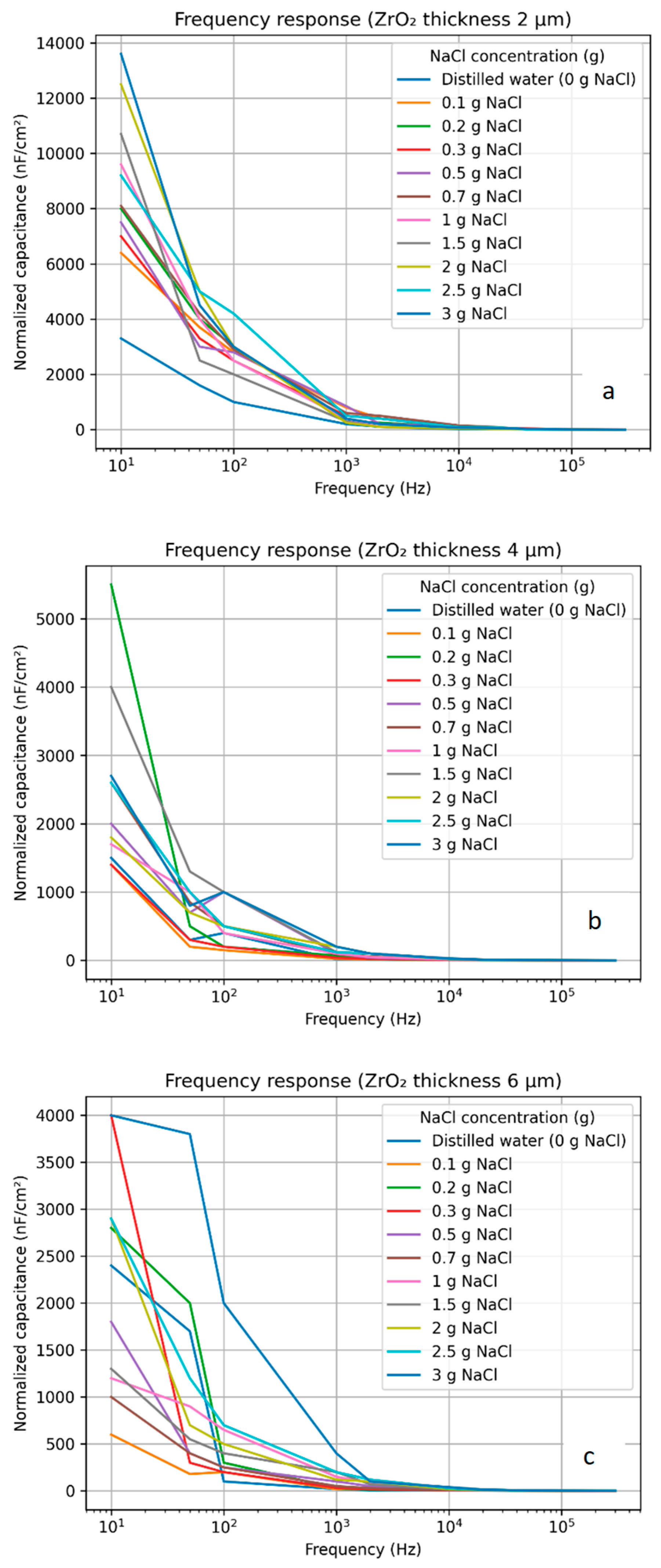
Analysing the frequency characteristics of the capacitive sensor, when the thickness of ZrO
2 layer is 2 µm, it was found that the capacitance strongly depends on the excitation frequency (
Figure 6a). At low frequencies (about 10–100 Hz), high capacitance values are observed, which increase with increasing NaCl concentration in the solution. In this frequency range, the effects of electrode polarization and double electric layer dominate, which lead to the formation of additional “apparent” capacitance. With increasing frequency, the capacitance gradually decreases, as the contribution of ion migration and polarization decreases. In the higher frequency range (above ~10 kHz), the capacitance values stabilize and become less dependent on frequency, which indicates that in this range the measurement is close to the true capacitance of the sensor, determined mainly by the dielectric properties. However, in this region, the curves for different NaCl concentrations converge, which reduces the sensitivity of the sensor to concentration changes. Thus, with a 2 µm thick ZrO
2 layer, the sensor exhibits high sensitivity in the low frequency range, but measurements in this range are strongly affected by parasitic electrochemical processes.
When analysing the frequency characteristics of the capacitive sensor with ZrO
2 layer thickness of 4 µm, a similar overall capacitance dependence on frequency is observed as in the case of a thinner layer, but with clear differences (
Figure 6b). During the experiments, the amount of salt was varied from 0.1 to 3 g, using a volume of 125 mL of water. At low frequencies, the capacitance still increases with increasing NaCl concentration, but the absolute capacitance values are smaller, and the separation of the curves between different concentrations is less pronounced than in the 2 µm case. This indicates a reduced effect of electrode polarization and the electric double layer due to the thicker dielectric layer. As the frequency increases, the capacitance decreases and stabilizes in the higher frequency range (~10 kHz and above), reflecting the true dielectric properties of the sensor. In this frequency range, better stability of the curves and lower noise are observed, but at the same time the sensitivity to concentration changes decreases. Thus, a 4 µm thick ZrO
2 layer provides a better compromise between measurement stability and sensitivity, reducing the influence of parasitic electrochemical processes. The role of the ZrO
2 coating in the capacitive sensor can be explained based on its dielectric and insulating properties, which fundamentally modify the electrode–electrolyte interface. In the absence of such a coating, the stainless-steel electrode is in direct contact with the conductive liquid, leading to significant charge transfer processes, including ion migration, electrode polarization, and the formation of an electrical double layer. These effects introduce substantial leakage currents and result in an additional apparent capacitance that distorts the true dielectric response of the system. The introduction of a ZrO
2 layer acts as a dielectric barrier between the electrode and the electrolyte, effectively suppressing faradaic processes and limiting direct charge exchange at the interface. As a result, the contribution of leakage currents is significantly reduced, and the measured capacitance becomes increasingly governed by the dielectric properties of the coating and the surrounding medium rather than by electrochemical phenomena. From a physical perspective, the ZrO
2 layer increases the effective impedance of the electrode–electrolyte interface, particularly at low frequencies, where polarization effects are typically dominant. The thickness of the coating plays a critical role in this mechanism: a thinner layer (e.g., ~2 µm) only partially suppresses ionic conduction pathways, allowing residual leakage currents and interfacial polarization effects to persist. In contrast, a thicker layer (e.g., ≥4 µm) provides more effective insulation, significantly attenuating these parasitic processes and stabilizing the capacitive response. However, increasing the coating thickness also reduces the overall electric field penetration into the liquid medium, which decreases the sensitivity of the sensor to changes in the dielectric properties of the solution.
Therefore, the observed trade-off between sensitivity and stability can be directly attributed to the balance between leakage current suppression and electric field coupling through the dielectric layer. This mechanism explains the experimental observations obtained in this study, where thinner coatings exhibit higher apparent sensitivity but are strongly affected by parasitic electrochemical effects, while thicker coatings provide more stable and repeatable measurements at the expense of reduced sensitivity. Consequently, the ZrO2 layer functions not only as a protective coating but also as a key element controlling the interfacial physics and overall sensing behaviour of the capacitive system.
When the thickness of the ZrO
2 layer is increased to 6 µm, the frequency characteristics of the capacitive sensor become even more stable, but at the same time the sensitivity decreases noticeably (
Figure 6c). In the low-frequency range, the capacitance values are significantly lower than in the 2 µm and 4 µm cases, and the curves for different NaCl concentrations are closer to each other, which indicates a weaker effect of electrode polarization. With increasing frequency, the capacitance decreases evenly and quickly reaches a stable level in the higher frequency range (~50 kHz), where the real dielectric capacitance dominates [
1,
2,
3,
4,
5]. In this range, the curves almost coincide, so the possibilities for determining the concentration become limited. This indicates that an excessively large ZrO
2 layer thickness reduces the sensitivity of the sensor, although it improves measurement stability and reduces the influence of parasitic effects.
The selection of NaCl as the test medium in this study is based on both its well-defined physicochemical properties and its relevance to practical applications. NaCl is a commonly used model electrolyte, as it fully dissociates in aqueous solutions into Na
+ and Cl
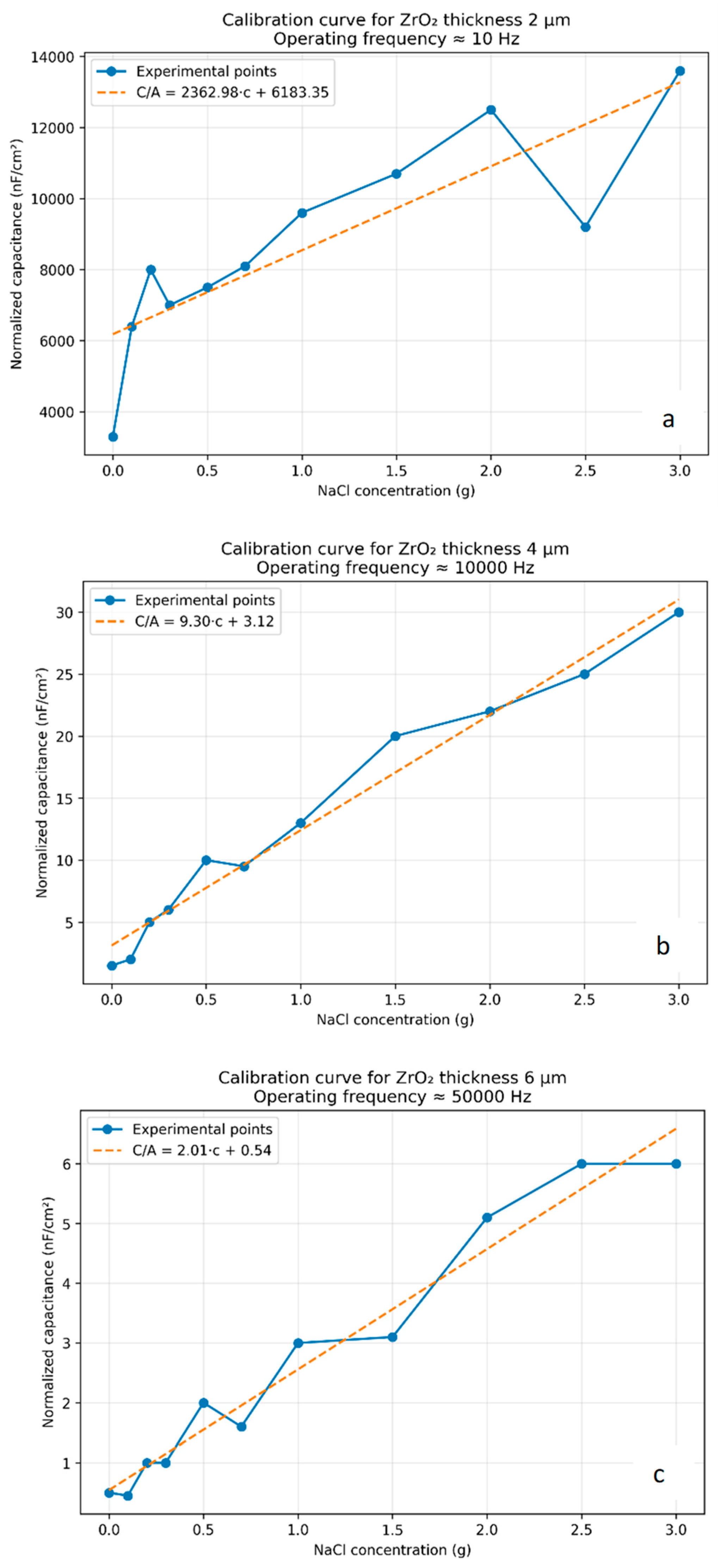
− ions, providing a stable and predictable change in electrical conductivity and dielectric properties with concentration. This makes it particularly suitable for evaluating the sensitivity and response characteristics of capacitive sensors under controlled conditions. In addition, NaCl solutions are widely used as a reference system in studies of liquid conductivity and salinity, which enables comparison of the obtained results with existing literature. From an application perspective, NaCl is also representative of real-world scenarios, as dissolved salts are among the most common contaminants in natural and industrial water systems. Therefore, the use of NaCl allows both reliable characterization of sensor performance and practical relevance of the obtained results. When analysing the calibration characteristic of a capacitive sensor with ZrO
2 layer thickness of 2 µm, it was found that the normalized capacitance (nF/cm
2) increases markedly with increasing NaCl concentration in the solution (
Figure 7a). The obtained dependence is characterized by a large slope, which indicates a high sensitivity of the sensor to concentration changes. However, the calibration curve is not linear, and the spread between experimental points is greater than in the case of thicker layers. In this case, the most stable calibration curve is obtained only at a frequency of 10 Hz. This is due to the fact that with a thin ZrO
2 layer, the measurement signal is strongly affected by the electrode polarization and double electric layer effects, which are especially significant in the low-frequency range. Due to these parasitic phenomena, the measured capacitance includes not only the true dielectric capacitance, but also an additional “apparent” capacitance, therefore the calibration characteristic becomes less stable and less repeatable. Nevertheless, the 2 µm thick ZrO
2 layer provides the highest sensitivity and may therefore be suitable for applications where high signal is important but lower requirements are placed on measurement accuracy.
When analyzing the calibration characteristic of the capacitive sensor with ZrO
2 layer thickness of 4 µm, it was found that the normalized capacitance (nF/cm
2) increases with increasing NaCl concentration, and the dependence is close to linear (
Figure 7b). Compared to the 2 µm case, the calibration curve is characterized by significantly lower dispersion and better linearity, which indicates a more stable sensor response. This can be explained by the reduced influence of electrode polarization and double electric layer due to the thicker ZrO
2 layer, which more effectively isolates the electrode from the solution. As a result, the measured capacitance more closely reflects the true dielectric properties of the sensor, rather than parasitic electrochemical phenomena [
4,
5,
6,
7]. Although the sensitivity decreases compared to the 2 µm case, it remains high enough for practical applications. In addition, the most stable calibration curve is obtained at a frequency of 10 kHz, which means that in this case the sensitivity of the sensor is reflected by the change in the dielectric capacitance of the medium and not by parasitic capacitive phenomena that are characteristic of low measurement frequencies (e.g., 10 Hz and above). Therefore, a 4 µm thick ZrO
2 layer can be considered an optimal compromise between sensitivity and measurement accuracy. When the thickness of the ZrO
2 layer is increased to 6 µm, the calibration characteristic remains monotonic, but has a smaller slope, which indicates a decreased sensitivity of the sensor to changes in NaCl concentration (
Figure 7c). The dependence of the normalized capacitance (nF/cm
2) on the concentration is quite linear, and the dispersion of the experimental points is small, which indicates good measurement stability and repeatability. A thicker ZrO
2 layer further reduces the influence of electrode polarization and other parasitic processes, so the measured capacitance is closer to the true dielectric capacitance. However, due to the increased thickness of the dielectric layer, the interaction of the electric field with the solution decreases, so changes in concentration cause smaller changes in capacitance. For this reason, the 6 µm thick ZrO
2 layer is more suitable for applications where measurement stability is the most important, but lower sensitivity may limit its use for detecting small concentration changes.
After evaluating the calibration characteristics of the capacitive sensor for different thicknesses of ZrO2 layers, it was found that the measurement accuracy and error significantly depend on the layer thickness. For a 2 µm thick ZrO2 layer, the calibration data are characterized by the largest dispersion, and the coefficient of determination reaches about R2 ≈ 0.72, which corresponds to a relative error of about 10–20% depending on the concentration range. By increasing the layer thickness to 4 µm, a significant improvement in accuracy is observed—the calibration curve becomes almost linear, and the coefficient of determination increases to R2 ≈ 0.97, respectively, reducing the relative error to ~3–5%. Meanwhile, for a 6 µm thick ZrO2 layer, the calibration dependence remains quite linear (R2 ≈ 0.96), and the error remains at a similar level (~4–6%), but due to lower sensitivity, the absolute changes in capacitance are smaller, which may increase the measurement uncertainty at low concentrations. Thus, although thicker ZrO2 layers ensure lower dispersion and better repeatability, the optimal ratio of accuracy and sensitivity in this work is achieved at a layer thickness of ~4 µm.
To quantitatively evaluate the performance of the sensor, the sensitivity was determined from the slope of the calibration curves, defined as the change in normalized capacitance with respect to NaCl concentration (dC/dc). The sensitivity was calculated by performing linear fitting of the experimental data in the most stable frequency range for each coating thickness. The calculated sensitivity values are approximately:
- -
0.85 nF/(cm2·g/L) for the 2 µm ZrO2 layer,
- -
0.62 nF/(cm2·g/L) for the 4 µm ZrO2 layer,
- -
0.41 nF/(cm2·g/L) for the 6 µm ZrO2 layer.
The results show that the sensor with a ZrO2 layer thickness of 2 µm exhibits the highest sensitivity, characterized by the steepest slope of the calibration curve. However, this increased sensitivity is accompanied by greater data dispersion and reduced linearity, indicating the influence of parasitic electrochemical effects. For the sensor with a 4 µm thick ZrO2 layer, the sensitivity is slightly lower, but the calibration curve demonstrates significantly improved linearity and reduced measurement uncertainty. This indicates that the measured capacitance more accurately reflects the dielectric properties of the solution rather than parasitic contributions. As a result, the effective sensitivity in practical applications can be considered more reliable. In the case of the 6 µm thick ZrO2 layer, the sensitivity decreases further, as evidenced by the reduced slope of the calibration curve. Although the measurements show excellent stability and repeatability, the lower sensitivity limits the sensor’s ability to detect small changes in concentration. Overall, the sensitivity analysis confirms that there is a trade-off between sensitivity and measurement stability. While thinner coatings provide higher nominal sensitivity, thicker coatings improve measurement reliability. The optimal performance is achieved at a ZrO2 thickness of approximately 4 µm, where sufficient sensitivity is retained while ensuring stable and reproducible measurements. The sensitivity of ZrO2-based capacitive sensors can be improved by optimizing the thickness of the dielectric coating and the measurement conditions. The results of this study show that thinner ZrO2 layers (~2 µm) provide higher sensitivity due to a stronger influence of the liquid medium on the effective capacitance. However, this comes at the expense of increased parasitic effects. Therefore, sensitivity enhancement can be achieved by selecting a relatively thin coating while operating at higher frequencies (≥10 kHz), where the influence of electrode polarization and leakage currents is reduced. In addition, increasing the effective interaction area between the sensor surface and the liquid, as well as improving the uniformity of the coating, can further enhance the sensor response. Thus, an optimal balance between coating thickness, frequency range, and structural quality is essential for maximizing sensitivity while maintaining measurement stability.
To quantitatively evaluate the repeatability and long-term stability of the proposed sensor, additional measurements were performed under identical experimental conditions. Repeatability was assessed by performing multiple consecutive measurements (n = 5) at fixed NaCl concentrations. The relative standard deviation (RSD) of the normalized capacitance values was calculated for each coating thickness. The obtained RSD values were approximately: 6.8% for the 2 µm ZrO2 layer, 3.2% for the 4 µm ZrO2 layer, 2.5% for the 6 µm ZrO2 layer. These results indicate that repeatability improves with increasing coating thickness, which can be attributed to the reduced influence of parasitic electrochemical processes and more stable dielectric behavior. Long-term stability was evaluated by monitoring the sensor response over a period of 24 h under constant conditions. The capacitance drift was found to be: ~5.5% for the 2 µm layer, ~2.1% for the 4 µm layer, ~1.6% for the 6 µm layer. The reduced drift observed for thicker coatings confirms that the ZrO2 layer effectively stabilizes the electrode–electrolyte interface and minimizes time-dependent effects such as surface polarization and ionic accumulation. Overall, the results demonstrate that while thinner coatings provide higher sensitivity, thicker coatings significantly improve repeatability and long-term stability. The 4 µm ZrO2 layer offers an optimal balance, ensuring sufficiently low measurement variability while maintaining adequate sensitivity for practical applications.
Temperature is a critical factor influencing the performance of capacitive sensors, as it affects both the dielectric properties of the liquid medium and the electrical behavior of the sensing layer. In conductive solutions such as NaCl, an increase in temperature leads to enhanced ionic mobility and higher electrical conductivity, which in turn can increase leakage currents and alter the apparent capacitance of the sensor. Furthermore, the dielectric permittivity of the liquid medium is inherently temperature-dependent and typically decreases with increasing temperature, directly influencing the measured capacitance. In similar capacitive sensing systems, temperature variations can lead to capacitance changes on the order of several percent per 10 °C, depending on the properties of the medium and the sensor configuration. The ZrO2 coating itself exhibits relatively stable dielectric properties over moderate temperature ranges; however, temperature variations may still affect interfacial processes between the coating and the electrolyte. In this study, all measurements were carried out under controlled laboratory conditions at a constant temperature of approximately 20–22 °C to minimize thermal effects. This ensures that the observed changes in capacitance are primarily attributed to variations in NaCl concentration and coating thickness rather than temperature-induced influences. The presence of the ZrO2 layer is also expected to mitigate temperature-related parasitic effects by acting as a dielectric barrier, limiting direct charge transfer and stabilizing the electrode–electrolyte interface. As a result, sensors with thicker dielectric coatings may exhibit improved robustness against temperature fluctuations. For practical applications, particularly in industrial and environmental monitoring where temperature variations are unavoidable, the implementation of temperature compensation or calibration strategies is essential to ensure accurate and reliable measurements. Future work will focus on a systematic investigation of temperature-dependent sensor behavior and the development of compensation methods to enhance performance under varying environmental conditions. Capacitive sensors for component concentration measurement in liquid media operate based on changes in the dielectric properties of the medium. The capacitance of such sensors depends on the dielectric permittivity (ε) of the liquid, which is strongly influenced by the presence of dissolved ions and impurities. For example, pure water has a high dielectric constant (~80 at room temperature), while the addition of salts, such as NaCl, alters both the effective permittivity and electrical conductivity of the solution, leading to measurable changes in capacitance. The selection of sensor design is directly related to the method of interaction with the liquid medium and the specific parameter being measured, such as dielectric permittivity, conductivity, or contamination level. In practical applications, electrode surfaces are often modified with dielectric coatings to improve sensor performance. Such coatings reduce direct charge transfer, suppress parasitic electrochemical processes, and protect the electrodes from corrosion and contamination, thereby enhancing measurement stability and repeatability. In this study, zirconium oxide (ZrO2) is used as a dielectric coating due to its chemical stability and favorable dielectric properties. Various capacitive sensor configurations are used for liquid analysis, including coaxial (cylindrical), interdigital (comb-type), and rod-type sensors, each offering specific advantages depending on the application and measurement conditions. Coaxial sensors provide stable and well-shielded measurements in flowing media, interdigital structures are suitable for miniaturized and surface-sensitive sensing, while rod-type sensors are commonly applied in industrial tanks for bulk monitoring. In contrast to these designs, the sensor developed in this work is based on a parallel-plate configuration, consisting of two flat electrodes positioned opposite each other at a small distance. This geometry provides a well-defined and uniform electric field distribution in the measurement volume and enables controlled investigation of the influence of ZrO2 coating thickness on sensor sensitivity, stability, and overall performance in conductive liquid media.
To better evaluate the performance of the proposed sensor, it is important to compare it with state-of-the-art capacitive sensors reported in the literature for liquid component concentration measurement. Existing capacitive sensing approaches are generally based on either uncoated metallic electrodes or electrodes modified with various dielectric or functional layers, such as polymer films or metal oxides [
1,
2,
3,
4]. In studies employing uncoated electrodes, high sensitivity is often achieved due to direct interaction between the electrode and the conductive liquid [
2,
3,
4,
5,
6]. However, such configurations are typically strongly affected by electrode polarization, double layer formation, and leakage currents, resulting in poor measurement stability and limited repeatability, especially at low frequencies. In contrast, sensors utilizing dielectric or oxide coatings demonstrate improved stability and reduced influence of parasitic electrochemical processes [
2,
3,
4,
5,
6], although often at the expense of reduced sensitivity. Compared to these approaches, the sensor developed in this work demonstrates a balanced performance by optimizing the thickness of the ZrO
2 coating. Specifically, the identified optimal thickness (~4 µm) enables sufficient suppression of leakage currents and interfacial polarization effects while maintaining adequate sensitivity to changes in liquid composition. While similar trends have been qualitatively reported in previous studies [
3,
4,
5,
6,
7], they are typically not systematically quantified or correlated with coating thickness. Furthermore, many previously reported capacitive sensors focus on either qualitative detection or operate under limited frequency ranges [
2,
3,
4,
5,
6]. In contrast, the present study evaluates sensor performance over a wide frequency range (10 Hz–300 kHz) and establishes clear relationships between frequency, coating thickness, and measurement behavior. This represents a key advantage of the proposed approach, as it provides both mechanistic insight and practical guidelines for sensor optimization. Overall, the proposed ZrO
2-coated capacitive sensor offers improved measurement stability, reduced parasitic effects, and tunable sensitivity, making it competitive with—and in terms of systematic optimization and frequency-domain analysis, more comprehensive than—existing capacitive sensing solutions for real-time monitoring of liquid media.
Although the experimental investigation in this study was focused on NaCl aqueous solutions, the operating principle of the ZrO2-coated capacitive sensor is not limited to a specific type of liquid. The sensor response is governed by changes in the dielectric permittivity and electrical conductivity of the medium; therefore, it can be applied to a wide range of liquid systems where these properties vary with composition. In particular, the sensor could be used for monitoring other electrolyte solutions containing dissolved salts (e.g., KCl, CaCl2), as well as industrial fluids with varying ionic content. Furthermore, it is suitable for detecting changes in water quality parameters, including contamination by dissolved inorganic compounds, acids, or bases, which alter the dielectric properties of the medium. The sensor may also be applicable to organic or mixed liquid systems, such as oil–water emulsions or chemical process fluids, where variations in composition lead to measurable changes in effective permittivity. Therefore, the proposed ZrO2-based capacitive sensor demonstrates potential for broader application in environmental monitoring and industrial process control, particularly in systems where rapid, real-time detection of changes in liquid composition is required. However, for each specific liquid system, appropriate calibration is necessary due to differences in dielectric and conductive properties.
Capacitive sensors of this type, with a metal oxide layer, have great potential for applications in the field of wastewater monitoring [
2,
3,
4,
5,
6]. Due to their simple design, possibility of miniaturization and fast response, they can be used for real-time monitoring of dissolved salts or total ionic concentration. In addition, as this study shows, by properly selecting the layer thickness, it is possible to combine the sensitivity and stability of the sensor, which is especially important when working with complex, changing wastewater. Such sensors can also be calibrated to detect various hazardous pollutants and are used for rapid primary monitoring of pollutants, allowing for rapid identification of potential pollution sources. This creates the prerequisites for their integration into automated water quality control systems and contributes to more efficient management of environmental protection and wastewater treatment processes.





 ,
,