


Abstract
The study presents an engineering solution for maintaining traffic flow during road and utility operations, such as trench excavation. The analysis of existing organizational and technical approaches, along with global experience in temporary bridge use, showed that most foreign analogs were developed for military purposes and are not fully suitable for urban conditions in Kazakhstan and CIS countries. As an alternative solution, the development of a mobile overpass adapted for operation in dense urban environments is proposed. The present study continues earlier research focused on optimizing the placement of mobile overpass supports while accounting for the nonlinear deformation behavior of the soil foundation. At the previous stage, a rational distance between the supports and the trench edge was substantiated, and horizontal soil deformations were reduced. In the current study, the primary focus is on the design of the undercarriage, which determines the mobility, stability, and operational feasibility of the structure. A morphological analysis and synthesis method is applied to select a rational configuration of the undercarriage. A 3D model and a 1:4 scale test bench were developed, followed by load tests of 50–200 kg. The maximum deflection of −1.19 mm at 200 kg demonstrated an almost linear deformation pattern. The constructed regression model () confirmed the accuracy and reliability of the design. The developed mobile overpass is versatile, cost-effective, and practical, improving the resilience of urban transport infrastructure, reducing traffic congestion during roadworks, and creating a foundation for serial production in Kazakhstan and CIS countries.
1. Introduction
In recent years, there has been a significant increase in the number of road vehicles in many countries, including Kazakhstan [1]. For example, in countries such as Germany [2], Japan, and the United States [3], vehicle density has risen substantially due to improved transport accessibility and rapid urbanization. This, in turn, has intensified the load on road transport infrastructure [4], increased traffic intensity, and led to chronic congestion [5]. Urban roadways are particularly vulnerable to serious traffic jams during road maintenance and repair operations [6]. Temporary reductions in the number of lanes [7] or complete closures of certain road sections [8] significantly decrease road capacity and are among the primary causes of traffic congestion. Such conditions not only increase travel delays for drivers but also result in economic losses, higher fuel consumption [9], and negative environmental impacts [10] due to elevated exhaust gas emissions [11].
Work zones are also characterized by higher accident rates, as irregular road markings, narrowed lanes [12], and unexpected driver maneuvers [13] frequently lead to traffic incidents. In dense urban areas, even short-term traffic restrictions [14] can severely disrupt traffic flows. The problem is particularly acute in the central districts of large cities, where the transport infrastructure operates near its maximum capacity and there is no spare bandwidth for redistribution of flows [15].
Various organizational and technical solutions are used to reduce traffic jams during road operations. The most effective ones include use of contra-flow traffic systems [16], temporary detour schemes [17], and the use of Intelligent Transportation Systems (ITSs) [18] for adaptive flow management and real-time optimization. Table 1 presents an analysis of these methods with their advantages and disadvantages.
Table 1.
Existing organizational and technical solutions reducing traffic jams during road operations.
The analysis shows that the existing methods are an adaptation measure rather than a radical elimination of the causes of traffic jams. They partially compensate for the negative impacts, but do not eliminate the traffic jam and road blockage problem itself. In this regard, the search for new promising solutions is relevant.
There is also another well-known way to keep traffic moving when repairing roads. These include temporary bridges [40] used over the areas under repair. Historically, the first such bridge was the Bailey Bridge (Figure 1a), created in the 1940s for military needs. It was assembled manually from modular metal elements, easily transported and quickly assembled [41]. Later, it was improved into the Medium Girder Bridge system (Figure 1b) (medium-span girder bridge) [42], used by the military and in the civilian sphere in more than 40 countries.
Figure 1.
Prefabricated bridge used for military and civil purposes. (a) Bailey Bridge. (b) Medium Girder Bridge.
Nowadays, modern companies such as Acrow (Parsippany, NJ, USA) and Mabey Bridge (Lydney, UK) also offer modular bridges for temporary crossings. For example, in the US, a 137 m long two-lane temporary Acrow (Parsippany, NJ, USA) bridge leased for the construction period was installed during the repair of the I-295 interchange [43]. This allowed for avoiding a complete traffic stop and saved time (Figure 2).
Figure 2.
Modular bridges for temporary crossings.
In Europe, the ASTRA Bridge (Federal Roads Office (ASTRA), Bern, Switzerland) developed in Switzerland became an innovative solution. This is a 257 m long portable bridge that carries traffic over the repair operations. The structure is mounted on motorized wheels and moves as the operations progress [44]. The system was successfully tested in 2022–2023 and generated interest in Germany and the UK (Figure 3).
Figure 3.
Portable ASTRA bridge (Federal Roads Office (ASTRA), Bern, Switzerland).
Similar technologies are also being developed in Asia. In Japan, an origami-based mobile folding bridge has been developed [45]; it can be deployed manually without heavy machinery, which significantly simplifies installation in constrained environments (Figure 4) [46].
Figure 4.
Origami-based mobile folding bridge.
In China, ultra-fast bridge replacement is practiced [47]. For example, in Beijing, a bridge was completely replaced in 43 h using launching technology [48]. Russia is developing its own engineering solutions for temporary bridges including modules created by the Research Institute of Transport and Road Management. These structures are assembled from welded beams of box-shapes or double T-section 6–12 m long, as well as prefabricated metal or reinforced concrete supports [49]. Installation is possible with the use of hydraulic jacks and light cranes, without the need for heavy machinery. Installation is possible using hydraulic jacks and cranes with low lifting capacity, without involving heavy machinery. Articulated joints and bolted assemblies allow the bridge to be assembled on site in 1–2 shifts by a small team. All the elements are transported on vehicles such as KAMAZ (KAMAZ PJSC, Naberezhnye Chelny, Russia), Volvo FMX (Volvo Group, Gothenburg, Sweden), Mercedes-Benz (Daimler Truck AG, Stuttgart, Germany) Arocs and other analogs. Such structures are characterized by low cost, high maintainability, and the possibility of use in remote areas. However, their load-bearing capacity is limited to 30–40 tons, there is no automation of the installation process, and the maximum speed on the bridge is 40–60 km/h. Military pontoon bridges, such as the PMP-3 (Russian military engineering system, Russia), designed for passage of heavy equipment, serve as an alternative. They consist of pontoons connected by coupling units and can carry up to 60 tons. A 300 m long bridge can be assembled in 4–6 h [50]. In emergency situations, such structures are re-equipped for civilian use, but require installation of additional elements, fencing, pavement, and lighting (Figure 5).
Figure 5.
Military pontoon bridge PMP-3 (Russian military engineering system, Russia).
Their advantages are high load-carrying capacity and speed of assembly, but they require specialized equipment and personnel, as well as certification for their use in civil infrastructure. Also in this sphere, there is our research on the development of a mobile overpass [51]. A mobile overpass is a single-span truss structure [52] with a reinforced metal frame, designed to organize a temporary passage of vehicles through dangerous road [53] sections or sections under repair [54] (Figure 6).
Figure 6.
Mobile overpass.
Standard rolled metal profiles are used in the design, which ensures its availability in production and ease of adaptation for different operating conditions [55]. One of the key features of this solution is the use of wheeled bogies, which perform a dual function [56]; they provide transportation of the structure and serve as intermediate supports when it is installed on site [57]. Due to its modular structure, the overpass is easily scalable, can be rapidly assembled, and does not require complex machinery, which is especially important in time- or resource-constrained environments. Ease of installation, versatility of the design, and cost-effectiveness make this option attractive for mass application, especially in the regions with limited opportunity for rapid reconstruction of road infrastructure.
The conducted analysis of engineering solutions applied in global practice during roadworks shows that the existing approaches can be systematized into three main groups: organizational and technical traffic management methods, temporary detour solutions, and engineering structures such as temporary bridges and mobile overpasses. The primary purpose of the first group is the redistribution of traffic flows without changing the physical structure of the road. However, these solutions do not eliminate the key limitation, namely the reduction in road capacity during repair works, but rather adapt the system to deteriorated operating conditions. The second group, temporary detours, makes it possible to completely exclude the repair zone from the main traffic flow. Despite their high effectiveness in terms of safety, their application is significantly limited in dense urban environments due to the lack of available space and the high costs associated with the construction of temporary infrastructure. The most promising direction is represented by the engineering solutions of the third group—temporary bridges and mobile overpasses. Their development can be conditionally divided into three stages: military prefabricated bridges (Bailey bridge (UK), Medium Girder Bridge (MGB) (UK)), universal modular bridge systems (Acrow (Acrow Bridge, Parsippany, NJ, USA), Mabey (Mabey Bridge, Lydney, UK), Janson (Janson Bridging, Hank, the Netherlands)), and modern mobile and movable structures (ASTRA Bridge (Federal Roads Office (ASTRA), Bern, Switzerland), MB4.0 (China)). A comparative analysis of the considered temporary bridges and the mobile overpass is presented in Table 2.
Table 2.
Comparative analysis of the considered options of temporary bridges and overpasses.
Based on Table 2, most temporary bridge solutions developed for military applications and highway infrastructure are characterized by high load-carrying capacity and modularity. However, their application in urban environments is associated with several significant limitations:
- The need for heavy machinery and long installation time;
- Low adaptability to confined urban intersection space;
- Orientation toward linear road sections rather than complex transport nodes;
- Lack of solutions ensuring high structural mobility within the urban road network.
Even the closest analog, the ASTRA Bridge ASTRA Bridge (Federal Roads Office (ASTRA), Bern, Switzerland), is primarily oriented toward highway applications and does not address the problem of rapid relocation and adaptability under conditions of dense urban development.
Among the considered solutions, the mobile overpass represents a relevant and practically significant engineering solution capable of effectively reducing traffic load in dense urban environments and under space constraints. Unlike most international analogs, the proposed design was developed from the outset with consideration of urban logistics. This determines its uniqueness and targeted applicability under conditions of high traffic density and constrained intersections.
However, the analysis of organizational, technical, and engineering approaches in the global context shows that existing developments are fragmented and focused on individual aspects—either traffic optimization, structural characteristics of bridge systems, or local engineering solutions. Therefore, there is a need for a comprehensive literature review aimed at generalizing existing research results, identifying the research gap, and determining insufficiently studied aspects. The results of the literature review are presented in Table 3.
Table 3.
Results of the literature review.
The results of the conducted analysis of scientific publications indicate the absence of a comprehensive, scientifically grounded engineering solution that ensures the continuity of traffic flow directly within roadwork zones through the integration of structural, technological, and operational requirements. Existing studies address this problem in a fragmented manner, focusing either on traffic flow optimization, reduction in construction time, or improvement of individual structural elements of bridge systems.
At the same time, studies devoted to mobile overpasses lack a systematic consideration of these structures as mobile transport engineering systems operating simultaneously in both transport and working modes. In particular, insufficient attention has been paid to the design of the undercarriage as a key functional element responsible for structural movement, maneuverability, precise positioning, stability under load, and load transfer to the supporting base.
Thus, the identified scientific and technical gap lies in the absence of scientifically substantiated undercarriage design solutions for mobile overpasses that ensure their efficient operation in dense urban environments while simultaneously meeting the requirements for load-carrying capacity, mobility, maneuverability, rapid deployment, and operational reliability.
The key role of the undercarriage is determined by the fact that it ensures the implementation of the main operational functions of the mobile overpass, including structural movement, precise positioning at the site, stability under load, and load transfer to the supporting base. At the same time, the analysis of existing design solutions shows that current undercarriage systems do not fully meet the requirements of urban operation. Their main disadvantages include high material consumption, limited driver visibility due to elevated wheel positioning, increased complexity of axle steering operations, low maintainability, and vulnerability to complex ground conditions.
The combination of these shortcomings indicates that existing undercarriage designs do not meet modern requirements for mobility, safety, and operational reliability, which necessitates their improvement based on scientifically grounded approaches.
Therefore, further development of mobile overpasses should be focused on improving the undercarriage as the functionally determining element of the system. This will ensure the required maneuverability in confined urban conditions, reduce deployment time, improve structural stability, and provide reliable operation under various loading and operating conditions. At the same time, the undercarriage design should account for:
- Maneuverability in confined urban intersections;
- Stability and reliability under loads up to 30 t;
- Ease of assembly and maintenance under limited time and resources;
- Compatibility with tractor trucks (KAMAZ (KAMAZ PJSC, Naberezhnye Chelny, Russia), URAL (Ural Automotive Plant, Miass, Russia) and analogs);
- Operability within a wide temperature range (from −40 to +40 °C).
Based on the above, the aim of the study is to develop the undercarriage design of a mobile overpass adapted to dense urban environments and intended to ensure rapid reduction in traffic load during roadworks, accidents, and other situations limiting the capacity of the road network. To achieve this aim, the following tasks were accomplished:
- A morphological table of undercarriage design parameters was developed;
- Requirements for the undercarriage of the mobile overpass were defined, taking into account maneuverability in confined intersections, load-carrying capacity and stability, compatibility with the tractor fleet, and operation under various climatic conditions;
- Synthesis of possible undercarriage configurations was performed and the optimal configuration was selected;
- A 3D model of the undercarriage and a scaled experimental test bench were developed to validate the design solutions;
- Experimental studies were conducted to evaluate the load and stability of the test bench;
- A regression equation describing the structural behavior under load was obtained and its convergence was assessed.
The scientific novelty of the study is as follows:
- For the first time, a systematic approach to undercarriage design based on morphological analysis and synthesis was proposed, enabling the transition from selecting individual design solutions to forming an optimal configuration based on a set of criteria (load-carrying capacity, maneuverability, weight, manufacturability, cost, and compatibility with transport vehicles);
- A new structural scheme of the undercarriage was developed, including a mechanical–pneumatic–electrical system that integrates transportation, installation, leveling, and fixation functions without the need for stationary foundations;
- A regression relationship describing structural behavior under load was obtained with high accuracy (R2 = 0.97), enabling prediction of overpass performance and application in engineering calculations.
The obtained results make a significant contribution to solving the problem of ensuring traffic flow during roadworks and are expressed as follows:
- A new class of engineering solutions is proposed, focused not on traffic adaptation but on the physical preservation of road capacity directly within the work zone;
- The identified scientific and technical gap related to the lack of integrated solutions combining mobility, structural reliability, and operational adaptability has been addressed;
- The possibility of rapid deployment of a mobile overpass in urban environments without extensive preparatory work and without the need for heavy machinery has been ensured;
- An engineering basis for the design of mobile overpasses applicable in countries with high traffic density has been established;
- Prerequisites for further development of regulatory frameworks and implementation of mobile overpasses in transport planning and urban infrastructure management have been formed.
Thus, in contrast to existing studies primarily focused on span structures or organizational measures, this work establishes a new approach in which the key object of research is the mobile undercarriage system of the overpass as the basis for its practical implementation in urban environments.
2. Materials and Methods
2.1. Morphological Analysis and Synthesis of the Overpass Undercarriage
According to the goals of the research, a morphological analysis was carried out for the mobile overpass undercarriage design. Morphological analysis is a theoretical method that allows one to systematically identify all possible variants of the design, technical solutions, or processes [54]. It is based on the extraction of classification features of an object and formation of all possible combinations of them in the form of a morphological table (also called the “black morphological box”) [55].
The algorithm for the morphological analysis includes:
- Determination of classification features of the design;
- Building of a morphology table;
- Analysis of the obtained combinations and selection of a rational variant [56].
The purpose of the morphological analysis was to study and systematize possible technical solutions for the design of the undercarriage of a mobile overpass used in urban environments to overcome trenches in utility networks.
To perform a morphological analysis of the mobile overpass undercarriage, key design parameters (classification features) were identified that affect its operability, mobility, compatibility with the urban environment, and technical characteristics. Fifteen such classification features were selected (Table 4).
Table 4.
Classification features of the undercarriage design.
The selected parameters have different origins and were defined considering both regulatory requirements and real operating conditions. First, regulatory constraints applicable in the Republic of Kazakhstan and other member states of the Eurasian Economic Union (EAEU) were taken into account, including permissible vehicle dimensions (not exceeding 2.55 m in width) [76], axle load limits, and traffic regulations [77]. The parameters of coupling devices were adopted in accordance with the requirements of GOST 2349 [78].
Operational parameters, including the temperature range (−40 to +40 °C), operating conditions (dust exposure, contamination, uneven road surfaces), and characteristics of tractor trucks (KAMAZ (KAMAZ PJSC, Naberezhnye Chelny, Russia), URAL (Ural Automotive Plant, Miass, Russia) and their analogs), were determined based on the analysis of operating conditions of transport platforms and trailer systems used in road construction and heavy structure transportation. This made it possible to account for real operating conditions of the mobile overpass and ensure the applicability of the proposed design in practical environments.
Ranges of operating speeds, load levels, and the selection of suspension types and tires were defined based on an analysis of structural and operational characteristics of serial trailer systems and transport modules. This ensured the comparability of the developed design with existing engineering solutions and increased the validity of the adopted parameters.
Some parameters, including permissible combinations of structural elements, as well as mass and cost constraints, were defined as engineering assumptions. These assumptions are based on generalized design experience and are aimed at ensuring mobility, manufacturability, and the practical feasibility of the structure.
Thus, all selected parameters have a justified origin, are consistent with regulatory requirements, and reflect real operating conditions of the designed system, which ensures the reliability and reproducibility of the obtained results.
All features and corresponding variants were summarized in a morphological table (Table 5).
Table 5.
All possible variants of the mobile overpass undercarriage.
Based on the compiled morphological table, the total number of all possible configurations of the overpass undercarriage (–) was established using the following formula:
We substitute the corresponding values:
In order to reduce the number of all possible configurations and to determine the optimal design of the overpass undercarriage, their synthesis was carried out. The synthesis allows for selecting one or more optimal configurations from all possible combinations of morphological table parameters, which corresponds to the goal of the research.
To perform the synthesis, the pros and cons of all the different variants were considered in terms of overpass undercarriage parameters (Table 6).
Table 6.
Pros and cons of all possible variants of the design parameters.
Based on the pros and cons of each variant, strict limitations were set to the selected configuration of the chassis, and only those variants that do not contradict the technical conditions, traffic regulations, dimensions, compatibility with KAMAZ (KAMAZ PJSC, Naberezhnye Chelny, Russia), Volvo FMX (Volvo Group, Gothenburg, Sweden), or Mercedes-Benz Arocs (Daimler Truck AG, Stuttgart, Germany), and requirements for operation in −40…+40 °C, as well as real speed and load modes, were retained (Table 7).
Table 7.
Limitations on selected chassis configuration.
The final number of feasible combinations after applying the constraints was calculated according to Equation (1) and amounted to
The evaluation was carried out by an expert group consisting of five specialists in transport engineering and structural design. The experts performed pairwise comparisons of the criteria according to their relative importance using a standard scale from 1 to 9 (where 1 indicates equal importance and 9 indicates strong dominance of one criterion over another). Based on these comparisons, a pairwise comparison matrix was constructed, from which the final weights of the criteria were calculated. In addition, the consistency of expert judgments was assessed. The obtained value of the consistency index () indicates that the expert opinions are consistent and can be considered reliable. The following factors were taken into account:
- Operating conditions (dense urban environment, confined space, ground clearance, temperature range from −40 to +40 °C);
- Requirements for reliability and safety during transportation and installation of the structure;
- Compatibility with the existing fleet of transport vehicles and ease of maintenance;
- Constraints related to weight and cost affecting the feasibility of serial production and implementation.
The resulting criteria weights are presented in Table 8.
Table 8.
Choice and weight criteria .
According to Table 8, the highest weight (0.3) was assigned to the reliability criterion, since structural failure during operation may lead to critical consequences, including accidents and disruption of traffic flow.
The criterion of compatibility with tractor trucks was assigned a weight of 0.2, as the ability to use the existing vehicle fleet is a prerequisite for the practical implementation of the mobile overpass.
The criteria of ground clearance and ease of maintenance were each assigned a weight of 0.15, as they determine the operational suitability of the structure under confined urban conditions, as well as the possibility of its use without specialized equipment and complex maintenance procedures.
The structural weight criterion was assigned a weight of 0.1, since, despite its influence on transportability and axle loads, it is considered an optimizable parameter that does not have a critical impact on system performance provided that regulatory constraints are satisfied.
A similar weight (0.1) was assigned to the cost criterion, as it affects economic efficiency and implementation feasibility; however, it is not a determining factor in the selection of the design solution compared to reliability and operational characteristics.
Thus, the adopted system of weighting coefficients reflects the priority of operational reliability and functional suitability of the structure over secondary parameters such as weight and cost.
Then, 5 most suitable configurations of the overpass undercarriage were chosen and assessed according to the above criteria (Table 9).
Table 9.
Optimal variants of configuration for the mobile overpass undercarriage.
The integral index was calculated for each configuration according to
where are the criteria weights (Table 8), and are the averaged scores for the criteria [57].
The methodology for calculating the integral index is as follows. Each configuration parameter (type of structure, frame, axles, load, clearance, speeds, tires, coupling device, suspension, etc.) was preliminarily evaluated according to six criteria: reliability, compatibility, maintenance, ground clearance, weight, and cost. The evaluation was performed using a five-point scale, where 1 corresponds to the lowest level of compliance with the criterion and 5 to the highest. Intermediate values reflect gradations of performance: low, medium, and high.
The expert evaluation was carried out by a group of five specialists with experience in transport engineering and structural design. Each expert independently assessed all parameters according to the selected criteria, after which the average score for each indicator was calculated.
To improve the objectivity of the results and reduce the influence of subjective factors, the following procedures were applied:
- Averaging of individual expert scores;
- Control of value dispersion (the standard deviation did not exceed );
- In the presence of significant deviations, verification and, if necessary, exclusion of extreme values.
It should be noted that differences in scores within the range of – fall within the acceptable limits of expert uncertainty and do not significantly affect the final ranking of alternatives. Nevertheless, these differences are taken into account in the calculation of the integral index, allowing for a more accurate comparison of configurations with similar characteristics.
The results of these calculations are presented in Table 10.
Table 10.
Averaged criteria scores .
Based on the obtained averaged criteria scores , the integral index of each configuration was calculated. An example of the calculation for configuration A is shown below:
By reliability:
By compatibility:
By maintenance:
By floatation ability:
By weight:
By cost:
The integral index for configuration A was calculated according to Equation (2):
Based on the above methodology, the integral index was calculated for other configurations. The calculation results are presented in Table 11.
Table 11.
Integral index of the configurations.
After comparative analysis by the criteria, the best combination turned out to be configuration A, which includes:
- Type of construction: low-frame 2-axle, ensures stability, acceptable load, and maneuverability;
- Primary function: transportation + stable fixation, a simple but safe solution;
- Chassis type: rigid welded frame with cross beams, reliability, and durability with moderate weight;
- Number of axles/wheels: 2 axles (4 wheels), balance between load-carrying capacity and maneuverability;
- Useful load: up to 10 t, suitable for passage of most vehicles and special equipment;
- Weight of the fully equipped chassis: about 3 t, strength with moderate weight;
- Fully loaded mass of the overpass: up to 13 t, permissible according to traffic regulations, compatible with standard tractor trucks;
- Dimensions: 10,900 × 2373 mm, fits into the shipping dimensions, sufficient support area;
- Road clearance: 380 mm, good ground clearance without loss of stability;
- Speed: up to 80 km/h on asphalt and 40 km/h on soil, safely and quickly;
- Tires: 10.00R20 OI-73B tire model (Russian specification)–reliable, unified for tractor trucks;
- Tire pressure: 5.75 kgf/cm2, optimum for load-carrying capacity and durability;
- Tow hitch: loop according to GOST 2349 H = 750 mm, full compatibility with traction trucks.;
- Suspension: semi-elliptic springs with shock absorption, simplicity, maintainability, vibration damping;
- Platform: movable carriages with rollers, precise positioning with minimum friction;
- Positioning drive: electromechanical cable, accuracy, reliability, operation at low temperature;
- Fixation of bridges: automatic, pneumatic cylinders with pins, fast, safe, no risk of human error;
- Pneumatic system power supply: from the tractor network, minimum additional equipment;
- Braking system: single-line pneumatic with diaphragm chambers 24, compatibility and reliability;
- Parking brake: separate circuit to the rear axle, hill holder;
- Emergency braking: auto-trigger in case of brake pipe failure, basic safety;
- Compatibility: KAMAZ, Volvo FMX or Mercedes-Benz Arocs and equivalents, ready for operation;
- Temperature range: −40…+40 °C, operation in most climatic zones of Kazakhstan and neighboring countries;
Thus, out of the possible combinations of parameters, the chosen configuration presents the optimal balance between functionality, reliability, mobility, and cost. This is neither the maximum in complexity nor the minimum in capability undercarriage configuration, but a rational middle option that covers all the key needs of mobile overpass operation.
2.2. Design Solution for the Suggested Overpass and Development of the Overpass Test Bench
According to the results of morphological analysis and synthesis, the design of a single-span overpass was developed, which is a prefabricated metal structure in the form of a spatial truss with a rigid frame (Figure 7).
Figure 7.
Construction of a single-span modular overpass in the operational position above the trench: 1—supporting structure (platform) of the mobile overpass; 2—movable suspension of the overpass; 3—side of the trench.
The design of the overpass (Figure 8a) is based on a stable triangular grid of longitudinal and diagonal links connected by vertical posts, which ensures high strength and uniform load distribution. The upper platform of the overpass is supported by two central wheeled trolleys with a biaxial undercarriage and pneumatic tires (Figure 8b), which serve as both a transport platform and an intermediate support in the working position.
Figure 8.
Three-dimensional model of the modular overpass with undercarriage: (a) overpass framework based on a triangular grid system; (b) wheeled trolley with biaxial undercarriage and pneumatic tires.
The halves of the span are joined in the middle zone by means of a hinge joint, which ensures continuity and uniformity of the roadway. Installation is carried out on compacted pads with possible use of damping layers to protect against vibration and shock loads. The undercarriage with controls and movement mechanisms is a set of structures that ensure transportation, stability, and maneuvering of the overpass (Figure 9).
Figure 9.
Structural diagram of the undercarriage of the overpass. (Explication of constructive elements: 1—drawbar of the overpass; 2—front suspension; 3—front suspension swivel; 4—front axle; 5—front driving wheel with tire; 6—front brake chamber; 7—pneumatic chamber for moving the finger of the front movable carriage; 8—upper platform; 9—compressed air receiver for finger movement of pneumatic systems; 10—compressed air receiver for pneumatic brakes; 11—rear suspension; 12—rear driving wheel with tire; 13—rear springs; 14—pneumatic chamber for finger movement of the rear movable carriage; 15—rear movable carriage; 16—rear axle; 17—rear brake chamber; 18—hose for pneumatic finger movement; 19—hose for pneumatic brakes; 20—brake valve for brake force distribution; 21—I-beam (connecting the front and rear); 22—front springs; 23—front movable carriage).
The design is based on the following:
- Wheel pairs with reinforced axles mounted on mobile carriages that move on longitudinal I-beams acting as guide rails;
- Shock absorption system—multi-leaf springs and hydraulic shock absorbers that reduce dynamic loads and ensure smooth running;
- Swivel mechanism of the front axle, which ensures maneuverability of the overpass during transportation;
- Cable actuating mechanism of transportation—the motor rotates a spool on which a cable is wound to move the carriage along the beam.
- Fixation in the desired position is ensured by a pneumatic lock, which is activated by the operator and locks the carriage with a locking pin.
- Pneumatic braking system—includes drum brakes, receiver and pneumatic valves connected to the tractor truck system by means of quick couplers.
- Electrical system—controls movement, lighting, and alarms (operates from 24 V with stabilization capability).
The adopted technical solution for the undercarriage allows for moving the structure on different types of road surfaces and positioning it accurately on the installation site without the need to build fixed foundations. This system ensures uniform distribution of loads from the span and vehicles traveling over the overpass, and reduces dynamic effects through damping. Given the high requirements for the strength, reliability, and adaptability of the structure, this engineering solution allows for the sustainable operation of the overpass throughout its temporary operation.
2.3. Development of an Experimental Overpass Test Stand
Based on the 3D modeling results, an overpass test bench was developed. The creation of the bench was the most important stage of the research, which allowed moving from theoretical design to practical realization of technical solutions. The development was carried out at a scale of 1:4 and included a full cycle of design, calculation, and production operations.
At the preparatory stage, the dimensions of the bench adapted to laboratory conditions were determined, and a list of necessary elements was made: metal profiles, fastening joints, moving and supporting assemblies. The main load-bearing parts were manufactured by laser cutting and bending, which ensured high geometric accuracy. The assemblies were joined by welding, bolted, or riveted connections, depending on the required rigidity and the need for subsequent disassembly.
Special attention was paid to the undercarriage of the overpass to ensure its mobility. It comprises:
- wheel pairs with reinforced axles mounted on mobile carriages;
- spring suspension that reduces dynamic loads during movement;
- fixation and locking mechanisms ensuring stability of the structure in the operating position.
To increase operational reliability, the undercarriage is coated with an anti-corrosion compound, and the main components are connected by welded and bolted elements, which increases rigidity and facilitates maintenance. The rear and front axles are mounted on movable carriages. The front axle is rotary, which ensures maneuverability of the overpass (Figure 10).
Figure 10.
Developed overpass undercarriage: (a) suspended position; (b) movement on wheeled undercarriage.
The front and rear chassis (Figure 11, pos. 1) are fixed on special structures: mobile carriages (Figure 11a,b, pos. 2). The carriages move left and right (horizontally) along the two longitudinal I-beam girders (Figure 11, pos. 4). Their movement is directed inward, closer to the center of the platform, which allows automatic adjustment of the axle position when the structure is in operation.
Figure 11.
Mobile carriage of the mobile overpass: 1—front and rear chassis; 2—mobile carriage; 3—connecting frame elements; 4—longitudinal I-beam girders.
A special mechanism is provided to facilitate the movement of the axles. Rollers are fastened on the surface of the beam, where the axles and carriages are installed (Figure 11, pos. 3)—four for each carriage. These rollers allow the structure to glide smoothly, while reducing friction and providing easy movement. Analysis of different options for mechanical solutions—rail, crawler and wheeled—showed the advantages of the latter: high maneuverability, ease of implementation, and versatility for use on different types of surfaces. The carriages move along the frame, along the longitudinal I-beams that act as guide rails (Figure 12).
Figure 12.
Front and rear suspensions moving along I-beam guides: (a) front suspension; (b) rear suspension.
Movement is performed by a mechanism involving an electric motor and a cable system. When power is supplied, the motor rotates the spool on which the cable is wound, moving the carriage (Figure 13). The axle position is changed by turning the special drum (Figure 13, pos. 1), to which force is applied via a cable (Figure 13, pos. 2). When the drum rotates, the rope tension changes, which causes the bridge to move (Figure 13, pos. 3) to the required position. An electric motor (Figure 13, pos. 4) actuates the movement, while ensuring accurate positioning.
Figure 13.
Mobile platform control mechanism: 1—drum; 2—cable; 3—movable carriage (bridge displacement); 4—electric motor.
The carriages are secured with a pneumatic lock: when the set position is reached, the operator activates the lock by pressing the button and the locking pin enters the hole on the overpass frame, securing the assembly.
Remarks to the Test Bench. The design of the original overpass includes pneumatic locks; however, when creating a model (scale 1:4), their application was impossible due to difficulties with the selection and installation of small-sized pneumatic chambers that would ensure correct operation of the mechanism in a reduced scale. In this regard, electronic clamps (electric pins) operating from a 12 V power supply were used for the test bench.
Electric pins perform the same function—insertion of the locking pin into the carriage bore—but they are controlled by an electrical signal. This preserved the functionality of the original system and ensured reliable fixation of the assemblies in laboratory conditions. The movable suspension in the stand is controlled by eight electronic clamps connected to the control panel and powered from a 12 V source.
Mobile carriages of the front and rear axles in shipment position are located at the extreme points of I-beam frame members and are rigidly fixed with electronic pins (Figure 14a,b, pos. 1).
Figure 14.
Mobile carriage fixation mechanism: (a) fixation mechanism with cylinder rods acting as steel fixators; (b) arrangement of carriages on the front axle; 1—electronic pins; 2—cylinder rods (steel fixators); 3—holes in the carriage body and I-beam flange.
The cylinder rods act as steel fixators (Figure 14a, pos. 2) and enter through holes made in the carriage body and the upper flange of the I-beam (Figure 14a, pos. 3). Two carriages are installed at each axle:
- On the rear axle—similarly, two carriages with four matching holes.
When compressed air is supplied from the tractor’s pneumatic system, the rod pin extends outward and, aligning with the holes, provides a rigid connection between the carriages and the frame, preventing longitudinal displacement of the axles. For travel, the carriages are released by switching the pneumatic valve (Figure 14a,b, pos. 1) to the “release” position: pressure is released and the rod and pin retract inside the cylinder, allowing the carriage to move freely along the girder to the next fixed position.
The choice of the pneumatic actuator in the original design is conditioned by the presence of a single tractor air system, which simplifies the design, reduces the weight of the assembly, and provides standardized maintenance. Additionally, the undercarriage is equipped with an air brake system including drum brakes, the receiver, and pneumatic valves. Pneumatic and electrical systems of the overpass are connected to the tractor systems by means of quick couplers.
The pneumatic braking system is powered by compressed air, which is supplied from the air intake valve of the towing vehicle through a special line hose. This air is accumulated in the air receivers (Figure 15a, pos. 1) and through the distributor valve (Figure 15a, pos. 2) is fed into the brake chambers (Figure 15a,b, pos. 3) of each wheel. When the driver presses the brake pedal, a valve automatically opens and compressed air flows through the hoses into the brake chambers, pressing the pistons against the jaws, which rest against the brake drum (Figure 15b, pos. 4). When the pedal is released, air is vented back into the atmosphere and the jaws release the brake drum, allowing the wheels to turn freely. In an emergency situation (for example, in case of a leaking line), an emergency valve is activated which completely blocks the air supply and sets the brake chambers in the “braking” position, safely keeping the trailer from moving. Therefore, the pneumatic system ensures smooth and safe deceleration of the overpass using simple and reliable compressed air control.
Figure 15.
Brake system of the mobile overpass: (a) pneumatic system components; (b) wheel braking mechanism; 1—air receivers; 2—distributor valve; 3—brake chambers; 4—brake drum.
The diaphragm brake chamber (Figure 15a,b, pos. 3), type 24, is designed to actuate the front and rear axle brakes.
Thus, the overpass undercarriage is an integrated mechanical–pneumatic–electrical system that ensures not only the movement of the structure, but also its reliable fixation, operational stability, and ease of operation. By combining cable and pneumatic actuators, as well as an autonomous electrical control system, the overpass is able to be moved quickly, positioned precisely, and brought into operation quickly without the need to connect to complex external infrastructure. The complex interaction of all components of the undercarriage guarantees high mobility, reliability, and safety when it is operated in urban areas, on construction sites or during road repair operations. This makes the mobile overpass a versatile engineering solution capable of adapting to different terrain conditions and traffic flow.
As a result, a mobile overpass test bench was developed, which recreates key structural elements and functional units at a scale of 1:4 (Figure 16).
Figure 16.
Overpass test bench.
This bench is the basis for a series of experimental studies aimed at studying the behavior of the overpass under various loads, including moving masses, vibrations, and static effects. Experimental research carried out on these benches allows for registering deflections, displacements, vibrational characteristics, and stability of the structure.
Experimental studies were carried out on a physical model of the mobile overpass at a geometric scale of 1:4 relative to the full-scale structure. To ensure the correct transfer of results to the real object, the principles of similarity theory and structural scaling were applied.
During modeling, the following similarity conditions were satisfied:
- Geometric similarity: All linear dimensions of the model were reduced by a factor of 4;
- Material similarity: The model was made of the same material (steel) as the full-scale structure, ensuring preservation of the elastic modulus E;
- Force similarity: Loads were scaled in accordance with similarity laws for bending structures.
Considering the geometric scale and identical material properties, load scaling was determined by the following relationship:
This relationship is explained by the fact that, in bending structures, the applied load is related to structural stiffness, which depends on the geometric characteristics of the cross-section, particularly the moment of inertia. When material properties remain unchanged, this leads to a quadratic relationship between load and the linear scale.
Thus, a load of applied to the model corresponds to
Similarly, the load range of 50– applied to the model corresponds to – at full scale.
Thus, the obtained values represent the initial operational loading conditions of the structure and allow assessment of its stiffness, deformability, and structural behavior under load. The linear load–deflection relationship confirms the correctness of the scaling approach and the applicability of the results to the full-scale structure.
2.4. Experimental Research Plan and Procedure
The main objective of the experimental studies on the developed test bench was to evaluate the performance of the overpass under the action of a moving load simulating the movement of a vehicle. This required determining the following:
- How loads are distributed on the upper platform of the overpass when a loading cart passes and what the deflection of the structure will be;
- Whether the structure of the overpass remains serviceable when the load is increased in steps up to 200 kg.
The preparation for the experiment involved several sequential steps that allowed for the creation of test conditions as close to realistic as possible. First, a loading cart in the form of a rigid rectangular frame on four wheels was made: the rear wheels were fixed and the front wheels were swivel, which provided maneuverability when moving. The cart was moved manually using a strong synthetic rope eight meters long, and bags of dry silica sand with stable bulk density were used as cargo. To ensure accuracy, the mass of each load unit (bag) was determined in advance using weighing scales. The use of bulk material made it possible to ensure a uniform distribution of load over the surface of the structure (Figure 17).
Figure 17.
Loading cart with bags: (a) loaded condition; (b) unloaded condition.
For the accuracy of the tests, the mass of each bag was pre-checked on both electronic platform scales and mechanical scales with dial indicators, which eliminated possible discrepancies. Next, the measuring equipment was installed. A PSK-MG4 (SKB Stroypribor, Chelyabinsk, Russia) deflection meter was used to measure the deformations and deflections of the suspension beam under load. Structurally, the deflection meter consists of an electronic unit, a clamp, a string with a tensioning weight, a clamping screw, and a remote control panel (Figure 18).
Figure 18.
PSK-MG4 deflection meter: 1—electronic unit; 2—clamp; 3—tensioning weight; 4—string; 5—clamping screw; 6—stand (user-supplied); 7—remote panel with a button.
Prior to testing, the instrument was fixed at the control point of the beam according to the developed installation scheme (Figure 19a). The readings were then checked at the zero position and, if necessary, calibrated (Figure 19b).
Figure 19.
(a) Deflection meter installation scheme. (b) Installed PSK-MG4 deflection meter for suspension beam deflection measurement.
The assessment of total measurement uncertainty was carried out based on the analysis of the main sources of error, including deflection measurement error and load application error. According to the technical specifications of the PSK-MG4 deflection gauge, the absolute measurement error within the range up to is . For measured deflection values of approximately 1–, this corresponds to a relative error of –.
The error in load application, associated with the use of pre-weighed bags filled with quartz sand, did not exceed –. Taking into account the combined influence of these factors, the total relative error was estimated as the sum of the individual components and amounted to approximately 5–.
The obtained value corresponds to an acceptable level for engineering experimental studies and does not have a significant effect on the reliability of the identified relationships.
At the same time, the mobile overpass structure itself was prepared: it was transferred from the shipping position to the operating position, installed over the trench, aligned longitudinally and transversely, and supported, and all assemblies were fixed. Guardrails, signal lights, and entry ramps were mounted on the upper platform, which ensured compliance with safety requirements and completeness of simulation of real operating conditions (Figure 20).
Figure 20.
Overpass test bench located over the trench.
Thus, the overpass, loading cart, and measuring instruments were brought into operating condition and prepared for experimental tests. The course of the experiment consisted of sequential loading of the mobile overpass structure using a specially prepared cart. Loads weighing 50, 100, 150, and 200 kg were alternately placed on the cart, after which it was manually moved along the bridge span using a synthetic rope. The movement was carried out smoothly, without jerks, in order to reproduce as accurately as possible the impact of a vehicle on the structure. To improve the reliability of the results and assess the repeatability of the experimental data, each load level was applied three times. Deflection measurements were performed for each repetition, followed by the determination of average values. Based on the test series, the mean deflection and standard deviation were calculated for each load level, characterizing the variability of the experimental data. The obtained results demonstrated a high degree of reproducibility: deviations between repeated measurements did not exceed acceptable limits, and the relative variation remained within the bounds of experimental error. Thus, the repeated tests confirm the reliability and reproducibility of the obtained data and allow their use for the analysis of the structural deformational behavior. While the cart was moving, the load was registered using the deflection meter. All measurement data were transferred to proprietary software provided with the PSK-MG4 device (SKB Stroypribor, Chelyabinsk, Russia) (Figure 21), where processing, plotting, and analysis of results were performed.
Figure 21.
The process of measuring and processing the results of deflection of the suspension beam of a mobile overpass using the PSK-MG4 deflection meter (SKB Stroypribor, Chelyabinsk, Russia).
Experimental research was carried out sequentially with an increase in the mass of the load, starting from 50 kg. This approach made it possible to determine the dependence of the structure’s deflection on the magnitude of the applied load and to evaluate its strength characteristics. Such a measurement method improved the precision and clarity of the obtained data while minimizing the influence of the human factor.
It should be noted that the conducted experimental study has several limitations associated with the applied methodology and modeling conditions.
First, the tests were performed on a physical model of the mobile overpass at a scale of 1:4. Despite the satisfaction of geometric and mechanical similarity, as well as the application of scaling theory, the transfer of results to the full-scale structure may involve additional factors not captured under laboratory conditions.
Second, the investigated load range (– in full-scale equivalent) corresponds to the initial operational level and does not cover the ultimate limit states of the structure. Therefore, the experimental results cannot be considered as confirmation of the load-carrying capacity under maximum design loads.
Third, the measurements were carried out under controlled laboratory conditions, which exclude the influence of external factors such as temperature-induced deformations, non-uniform support conditions, material wear, and real operating conditions in an urban environment.
Despite these limitations, the obtained results allow for a reliable assessment of the deformation behavior of the structure, confirm the validity of the adopted engineering solutions, and can serve as a basis for further analytical and experimental studies, including full-scale testing.
3. Results
3.1. Analysis of the Experimental Research Result
The results of experimental research performed for the overpass bench are presented in Table 12.
Table 12.
Experimental research results.
Based on the results of the experimental research, a graph was drawn up showing the changes in the deflection of the overpass depending on the mass of the applied load and the point of its location along the overpass (Figure 22).
Figure 22.
Change in the overpass deflection value depending on the load mass and points of its location along the overpass.
In the course of the experimental research, the dependence of the overpass deflection on the load magnitude was examined. The plotted curves for loads of 50, 100, 150, and 200 kg exhibit a parabolic shape, with maximum deflection values occurring at the midspan, while near the supports the deformations tend to zero. This trend is typical for beam-type structures subjected to bending, confirming the correctness of the experimental setup. As the load increased, a corresponding increase in the deflection magnitude was observed: for 50 kg the maximum deflection was approximately −0.36 mm; for 100 kg −0.65 mm; for 150 kg −0.95 mm; and for 200 kg −1.19 mm.
Thus, with a fourfold increase in the load, the maximum deformation increased by approximately 3.3 times, indicating a close to linear dependence between load and deflection within the studied range. Minor deviations from the strict proportionality can be explained by the elastic and plastic properties of the material and measurement features. At the same time, the shape of the curves remains symmetrical relative to the middle of the span, and the deflection values at symmetrical points coincide, which indicates uniform operation of the structure and the absence of distortions or asymmetries in the load distribution. The results obtained allow us to conclude that when exposed to loads of up to 200 kg, the overpass retains the elastic nature of deformations, and the increase in deflections occurs gradually, without sudden jumps, which confirms sufficient rigidity of the structure. The greatest deformations are concentrated in the central zone of the span, which should be taken into account when designing reinforcements and assessing the operational reliability of the structure.
Based on the results of the experimental research, a regression equation [79] was developed that describes the change in the overpass deflection depending on the mass of the applied load and the distance between points along the overpass x.
The deflection indicators were compared in the experiment and in the regression equation (Table 13).
Table 13.
Comparison of the deflection indicators in the experiment and regression equation.
Based on the compiled regression equation, a graph is presented showing a comparison of the actual (experimental) and estimated (according to the regression equation) deflection values (Figure 23).
Figure 23.
Comparison of actual (experimental) and estimated (according to the regression equation) deflection values.
According to the graph, there is a close convergence of the results from the experiment and the regression equation. In particular, the determination coefficient means that the regression equation explains almost 98% of the scatter of experimental data, which indicates the high accuracy of the selected equation. The correlation coefficient value indicates a strong linear relationship between the estimated and actual deflection values. Moreover, the average approximation error is less than 6.6%, which indicates that the equation very accurately reproduces the experimental results.
A mathematical analysis of the regression equation [80] was carried out. The partial derivatives were obtained according to Equation (11).
By weight m:
By distance x:
Then, a system of two equations with two unknown values (m and x) was compiled:
Solving this system gives
Thus, the critical point of the surface was found—the point where the function may have a minimum, maximum, or saddle point. The critical point at means that at these values the weight and distance give the condition where the structure deflection ceases to change—it neither increases nor decreases.
However, the weight value has no physical meaning, because the cart weight cannot be negative. Therefore, this extremum lies outside the acceptable physical domain. Within the actual ranges
the function increases monotonically by weight and has a maximum by distance.
Hessian Determinant
The Hessian determinant was calculated to determine the curvature of the function surface near the critical point [81]. The matrix of second derivatives has the form:
Since the determinant of the Hessian matrix is negative, , the regression equation surface is characterized by a saddle point in the variable space . This means that the function is not strictly convex or concave but has directions in which it increases and directions in which it decreases.
Next, the Hessian trace was identified. The Hessian trace is the sum of the diagonal elements of the Hessian matrix, that is, the sum of the second derivatives with respect to each variable. It reflects the total “convexity” or “concavity” of the function in all directions. If the trace is positive, then on average the function at this point is curved upward; if it is negative, it means that the function is curved downward.
As a result of the mathematical analysis, it was established that the determinant of the Hessian matrix satisfies the condition . Therefore, the surface of the regression function has a saddle point. This means that the function increases in one direction and decreases in another. However, the saddle point found corresponds to negative load and distance values and, therefore, lies outside the physically feasible region.
Within the limits of real parameter values, the function demonstrates the expected physical behavior:
- The deflection increases monotonically with increasing load;
- Along the distance, the maximum deflection is observed in the middle part of the span, which corresponds to the classical picture of beam bending on supports.
Based on the above, a graph was developed that represents a three-dimensional surface of the change in the deflection . The surface was constructed using the regression equation with the overlay of contour lines and experimental data. The abscissa axis shows the load weight L in the range of 50 to 200 kg, the ordinate axis shows the distance along the span D (– m), and the applicate axis shows the deflection of the structure in millimeters (Figure 24).
Figure 24.
Change in deflection indicators depending on the load weight (m) and distance between points (x).
Analysis of the surface shows that the deflection naturally increases with increasing load mass, and a characteristic dependence is observed along the span coordinate: the maximum values occur in the middle of the span, while near the supports the deflection decreases. This effect fully corresponds to the classical picture of the operation of a beam on supports under the effect of a load.
Contour lines drawn on the projection of the “floor” make it possible to clearly trace the change in deflection depending on both parameters and confirm the natural increase in deformations with increasing weight. Experimental points, shown by various markers for the loads of 50, 100, 150, and 200 kg, are located in close proximity to the surface of the regression model, which indicates a high degree of agreement between the theoretical calculations and experimental data. Minor discrepancies are explained by the experimental error and the characteristics of the actual loading of the structure.
The presented graph demonstrates the correctness of the built regression dependence and its adequacy in describing the physical behavior of the structure: the deflection increases monotonically with increasing load and has a maximum in the central part of the span. Overlaying experimental points on the surface allows for a visual confirmation of the reliability of the results and for using the model to predict the behavior of the overpass under operational loads.
Thus, the analysis carried out confirms the adequacy of the developed regression equation. It correctly reflects the physical laws of the structure: the deflection increases with increasing load and has a parabolic distribution along the span. The presence of an extremum outside the permissible region does not affect the actual operation of the structure. The constructed model is stable and can be used to predict the behavior of the overpass under operational loads.
During the processing of experimental data obtained from measuring overpass deflections at various points of the span, a transition was made from local values to integral indices. For this purpose, the areas of geometric figures (triangles and trapezoids) bounded by the deflection line and coordinate axes were calculated. This method makes it possible to quantify not only the deflection at a specific point but also the total impact of the load on the span. The calculation was carried out using the trapezoidal area formula, where the values of deflections at adjacent points were taken as the bases, and the distance between them as the height.
Based on experimental measurements of deflections at control points of the span, an integral assessment of the effect of the load [82] was performed. For each combination of the cart weight (50, 100, 150, and 200 kg) and its position along the span length (0.6–3.6 m), the areas under the deflection curve were calculated using the trapezoidal method. The resulting areas reflect the integral effect of the load on the structure and make it possible to move from local deformations to a quantitative assessment of the overall structural performance.
The load force was determined as
and for a uniformly distributed load
where m is the section length.
The work of the distributed load was calculated using the following expression:
and, for comparison, the work of a point load applied at the center of the span was calculated as
Additionally, the equivalent rigidity at the central point was determined as the following ratio:
The calculation results are presented in Table 14.
Table 14.
Index calculation results.
Based on the obtained calculation results, graphs of the dependence of the load mass on the area under the deflection curve, load work, deflection at the center of the span, and equivalent rigidity were developed (Figure 25).
Figure 25.
Graphs of the dependence of the load mass on the area under the deflection curve, load work, deflection at the center of the span, and equivalent rigidity.
According to the developed graphs, it follows that the total areas under the deflection curve increased from 0.0009 m2 with a mass of 50 kg to 0.0029 m2 with a mass of 200 kg. At the same time, the load work ranged from 0.07 to 0.96 J for the distributed diagram and from 0.09 to 1.17 J for the point diagram. The equivalent rigidity of the structure varied in the range of 1.3 to 1.65 MN/m, while demonstrating stability, and there was only a slight increase with increasing load, which can be explained by experimental errors and slight nonlinearity of the deformation.
Thus, the integral assessment confirmed the pattern: with increasing weight, deflections and load work increase almost linearly. The work values are in the range of up to 1.2 J, which reflects the characteristic expenditure of energy of the structure for elastic deformation. The use of the method of areas under the deflection line made it possible to move from individual point measurements to a comprehensive analysis, which can be used to assess the durability and calculate the service life of bridge and overpass structures under operating conditions.
4. Discussion of the Research Results
The obtained research results are aimed at solving a scientific problem related to ensuring the continuity of traffic flow under roadwork conditions in dense urban environments. Unlike existing solutions focused on traffic flow redistribution or reducing road closure duration, the proposed approach is based on the physical preservation of road capacity directly within the work zone. This fundamentally changes the nature of the problem and makes it possible to eliminate the identified scientific and technical gap, which consists in the absence of scientifically substantiated undercarriage design solutions for mobile overpasses that ensure their efficient operation in dense urban environments, including structural transportation, positioning within the work zone, stability under loading, and interaction with the supporting base.
In contrast to existing studies, where bridge structures are predominantly considered as stationary infrastructure elements, the present work treats the mobile overpass as an integrated transport engineering system, in which the undercarriage acts as the functionally determining element ensuring its practical feasibility in urban conditions.
The scientific contribution of the study lies not only in the development of a specific structural solution but also in the formation of a methodological approach to the design of mobile overpass undercarriages. In particular, the use of morphological analysis is proposed for the systematic synthesis of design solutions, taking into account a combination of operational, technical, and economic factors. This approach enables a transition from the selection of individual components to the formation of an optimal configuration based on a set of criteria. In addition, a method of experimental verification based on scaled modeling is substantiated, ensuring the transfer of results to full-scale structures.
The obtained regression relationship describing the structural behavior under load represents a tool for quantitative assessment of overpass deformability and can be used for predicting its performance and optimizing undercarriage parameters at the design stage.
Thus, the results of the study demonstrate the possibility of transitioning from the concept of traffic flow adaptation to the concept of physical preservation of road capacity directly within the work zone. The proposed approach establishes a new direction in the field of transport infrastructure based on the development of mobile overpasses with a functionally integrated undercarriage system.
It should be noted that the conducted study has several limitations associated with the applied methodology and modeling conditions. The tests were performed on a physical model of the mobile overpass at a scale of 1:4, which, despite satisfying the conditions of geometric and mechanical similarity, does not fully account for all factors affecting the behavior of the full-scale structure. In addition, the investigated load range (– in full-scale equivalent) corresponds to the initial operational level and does not cover the ultimate limit states of the structure. The measurements were carried out under laboratory conditions without considering the influence of external operational factors such as temperature-induced deformations, support conditions, and material wear.
Despite these limitations, the obtained results allow for a reliable assessment of the structural behavior and confirm the validity of the adopted engineering solutions. They provide a foundation for further development of this research area, primarily in improving the undercarriage design of the mobile overpass as a key system element.
Promising research directions include the study of structure–foundation interaction, as well as the development of numerical models that account for complex operational scenarios.
Additionally, an important direction is the development of a regulatory and technical framework governing the design, operation, and application of mobile overpasses in accordance with the requirements of urban transport infrastructure.
5. Conclusions
The study addresses a relevant scientific and engineering problem aimed at ensuring the continuity of traffic flow during roadworks in dense urban environments through the development and substantiation of the undercarriage design of a mobile overpass. The analysis of existing organizational, technical, and engineering solutions has shown that they do not ensure the preservation of road network capacity, but rather adapt traffic flows to deteriorated operating conditions. This made it possible to justify the need for a fundamentally new approach based on the physical preservation of traffic directly within the work zone.
Within the framework of the study, a systematic approach to the design of the mobile overpass undercarriage has been proposed, based on morphological analysis and synthesis. This made it possible to define a space of feasible design solutions and to select a rational configuration considering a set of criteria, including load-carrying capacity, maneuverability, weight, manufacturability, and compatibility with transport vehicles. A structural scheme of the undercarriage has been developed, including a mechanical–pneumatic–electrical system that integrates transportation, installation, leveling, and fixation functions without the need for stationary supporting foundations.
Experimental studies have shown that the developed structure possesses sufficient stiffness and stability: the maximum deflection reached 1.19 mm under a load of 200 kg, and the load–deflection relationship is close to linear. The obtained regression model with a high level of reliability () confirms the adequacy of the adopted engineering solutions and allows its use for predicting the structural behavior under load.
At the same time, the applied model and the conducted studies have several limitations that should be considered when interpreting the results. First, the experimental tests were performed on a scaled model (1:4), which requires caution when extrapolating the results to a full-scale structure, especially considering possible nonlinear scaling effects. Second, the experimental results cannot be considered as confirmation of the load-carrying capacity of the overpass under maximum design loads. Third, the computational model includes simplifying assumptions related to uniform load distribution and idealized boundary conditions, which may differ from real operating conditions. In addition, the influence of operational factors such as material wear, temperature-induced deformations, and environmental effects was not considered within the scope of this study. The obtained results confirm that the developed mobile overpass represents an effective engineering solution that ensures the preservation of road network capacity within work zones, reduces traffic congestion, and improves traffic safety. The practical significance of the study lies in the possibility of implementing the proposed design in urban infrastructure, as well as in forming an engineering basis for further design and deployment of similar systems.
Future research directions are associated with further development and refinement of the obtained results. First, full-scale testing under real operating conditions is required to validate the model and verify its scalability. An important direction is the consideration of dynamic loads and the development of more advanced models accounting for the interaction between the structure and traffic flow. Another promising direction is the study of automation of positioning and control processes of the mobile overpass, as well as its integration into Intelligent Transportation Systems. In addition, the development of a regulatory and technical framework governing the application of mobile overpasses in urban environments is required, along with an assessment of their effectiveness at the level of the urban transport system.
Thus, the conducted study forms a scientifically grounded basis for the development and implementation of next-generation mobile overpasses aimed at improving the resilience and efficiency of urban transport infrastructure.
Author Contributions
Conceptualization, A.K. (Adil Kadyrov); Methodology, A.K. (Adil Kadyrov) and A.K. (Aliya Kukesheva); Software, A.Z.; Validation, A.K. (Aliya Kukesheva), A.G. and K.S.; Formal Analysis, A.K. (Aliya Kukesheva); Investigation, K.S., A.Z. and Z.Z.; Resources, A.Z.; Data Curation, K.S.; Writing—Original Draft Preparation, A.K. (Aliya Kukesheva); Writing—Review and Editing, A.K. (Adil Kadyrov) and A.G.; Visualization, A.K. (Aliya Kukesheva), A.Z. and N.Z.; Supervision, A.G.; Project Administration, A.K. (Adil Kadyrov); Funding Acquisition, A.G. All authors have read and agreed to the published version of the manuscript.
Funding
This research has been/was/is funded by the Science Committee of the Ministry of Science and Higher Education of the Republic of Kazakhstan (Grant No. AP23487832).
Institutional Review Board Statement
Not applicable.
Informed Consent Statement
Not applicable.
Data Availability Statement
The original contributions presented in this study are included in the article. Further inquiries can be directed to the corresponding authors.
Conflicts of Interest
The authors declare no conflicts of interest.
Abbreviations
| ASTRA | Automated Safe Traffic Relief Arrangement Bridge (Switzerland) |
| CIS | Commonwealth of Independent States |
| DIN | Deutsches Institut für Normung (German Institute for Standardization) |
| HDGS | Hot-Dip Galvanized Steel |
| ITS | Intelligent Transportation Systems |
| KAMAZ | Kama Automobile Plant (Russia) |
| MGB | Medium Girder Bridge (UK, military) |
| MLC | Military Load Classification |
| PMP-3 | Pontoon Bridge PMP-3 (Russia) |
| RDB | Rapidly Deployable Bridge (USA/Germany) |
| RF | Russian Federation |
| UK | United Kingdom |
| USA | United States of America |
| Volvo FMX | Volvo FMX Truck (Sweden) |
References
- Sabraliev, N.; Abzhapbarova, A.; Nugymanova, G.; Taran, I.; Zhanbirov, Z. Modern aspects of modeling of transport routes in Kazakhstan. News Natl. Acad. Sci. Repub. Kazakhstan Ser. Geol. Tech. Sci. 2019, 2, 62–68. [Google Scholar] [CrossRef] [Scilit]
- Bräuninger, M.; Teuber, M.-O. The development of the passenger car population in Germany [Die Entwicklung des Pkw-Bestands in Deutschland]. Wirtschaftsdienst 2023, 103, 280–282. [Google Scholar] [CrossRef] [Scilit]
- Gao, Y.; Zhu, J. Characteristics, impacts and trends of urban transportation. Encyclopedia 2022, 2, 1168–1182. [Google Scholar] [CrossRef] [Scilit]
- Lu, J.; Li, B.; Li, H.; Al-Barakani, A. Expansion of city scale, traffic modes, traffic congestion, and air pollution. Cities 2021, 108, 102974. [Google Scholar] [CrossRef] [Scilit]
- Kumar, M.; Kumar, K.; Das, P. Study on road traffic congestion: A review. In Recent Trends in Communication and Electronics; Routledge: Oxfordshire, UK, 2021; pp. 230–240. [Google Scholar]
- Mahasirikul, N.; Aksorn, P.; Kusonkhum, W. Driving speed and hazardous location in construction work zone: Case of highway 2 Hin Latnon–Sa At. Geomate J. 2021, 20, 143–151. [Google Scholar] [CrossRef] [Scilit]
- Bagloee, S.A.; Sarvi, M.; Ceder, A. Transit priority lanes in congested road networks. Public Transp. 2017, 9, 571–599. [Google Scholar] [CrossRef] [Scilit]
- Yue, W.; Li, C.; Mao, G. Urban traffic bottleneck identification based on congestion propagation. In Proceedings of the 2018 IEEE International Conference on Communications (ICC); IEEE: New York, NY, USA, 2018; pp. 1–6. [Google Scholar] [CrossRef] [Scilit]
- Boggio-Marzet, A.; Monzon, A.; Rodriguez-Alloza, A.M.; Wang, Y. Combined influence of traffic conditions, driving behavior, and type of road on fuel consumption: Real driving data from Madrid area. Int. J. Sustain. Transp. 2022, 16, 301–313. [Google Scholar] [CrossRef] [Scilit]
- Al-Arkawazi, S.A.F. Measuring the influences and impacts of signalized intersection delay reduction on fuel consumption, operation cost and exhaust emissions. Civ. Eng. J. 2018, 4, 552–571. [Google Scholar] [CrossRef] [Scilit]
- Marve, S.R.; Bhorkar, M.; Baitule, P. A survey on environmental impacts due to traffic congestion in peak hours. Int. J. Sci. Technol. Eng. 2016, 2, 151–154. [Google Scholar]
- Yousif, S.; Nassrullah, Z.; Norgate, S.H. Narrow lanes and their effect on drivers’ behaviour at motorway roadworks. Transp. Res. Part F Traffic Psychol. Behav. 2017, 47, 86–100. [Google Scholar] [CrossRef] [Scilit]
- Tselentis, D.I.; Papadimitriou, E. Driver profile and driving pattern recognition for road safety assessment: Main challenges and future directions. IEEE Open J. Intell. Transp. Syst. 2023, 4, 83–100. [Google Scholar] [CrossRef] [Scilit]
- Stueger, P.N.; Fehn, F.; Bogenberger, K. Minimizing the effects of urban mobility-on-demand pick-up and drop-off stops: A microscopic simulation approach. Transp. Res. Rec. 2023, 2677, 814–828. [Google Scholar] [CrossRef] [Scilit]
- Jilani, U.; Asif, M.; Zia, M.Y.I.; Rashid, M.; Shams, S.; Otero, P. A systematic review on urban road traffic congestion. Wirel. Pers. Commun. 2025, 140, 81–109. [Google Scholar] [CrossRef] [Scilit]
- Huang, Z.; Loo, B.P. Urban traffic congestion in twelve large metropolitan cities: A thematic analysis of local news contents, 2009–2018. Int. J. Sustain. Transp. 2023, 17, 592–614. [Google Scholar] [CrossRef] [Scilit]
- Fu, Q.; Tian, Y.; Sun, J. Modeling and simulation of dynamic lane reversal using a cell transmission model. J. Intell. Transp. Syst. 2022, 26, 717–729. [Google Scholar] [CrossRef] [Scilit]
- Kitano, A.; Yoshihiro, T. Controlling detour vehicle volume for stable congestion mitigation in route guidance systems. Sens. Mater. 2024, 36, 4483–4499. [Google Scholar] [CrossRef] [Scilit]
- Stojanovic, N.; Grujic, I.; Boskovic, B. Application of intelligent transport systems in road traffic: A review. In Proceedings of the International Conference “New Technologies, Development and Applications”; Springer Nature: Cham, Switzerland, 2023; pp. 646–651. [Google Scholar] [CrossRef] [Scilit]
- Pérez-Méndez, D.; Gershenson, C.; Lárraga, M.E.; Mateos, J.L. Modeling adaptive reversible lanes: A cellular automata approach. PLoS ONE 2021, 16, e0244326. [Google Scholar] [CrossRef] [Scilit]
- Ampountolas, K.; Dos Santos, J.A.; Carlson, R.C. Motorway tidal flow lane control. IEEE Trans. Intell. Transp. Syst. 2019, 21, 1687–1696. [Google Scholar] [CrossRef] [Scilit]
- Maksimchuk, O.V.; Borisova, N.I.; Panov, D.B.; Voronkova, G.V. Sustainable development of road transport infrastructure by including elements of reverse traffic in the “smart city” program. IOP Conf. Ser. Earth Environ. Sci. 2022, 988, 022072. [Google Scholar] [CrossRef] [Scilit]
- Adanu, E.K.; Agyemang, W.; Lidbe, A.; Adarkwa, O.; Jones, S. An in-depth analysis of head-on crash severity and fatalities in Ghana. Heliyon 2023, 9, e18937. [Google Scholar] [CrossRef] [Scilit] [PubMed]
- Babić, D.; Babić, D.; Fiolic, M.; Ferko, M. Road markings and signs in road safety. Encyclopedia 2022, 2, 1738–1752. [Google Scholar] [CrossRef] [Scilit]
- He, Y.; Deng, X. Research on the application of reversible lanes in urban road traffic accidents emergency evacuation. J. Wuhan Univ. Technol. Transportation Sci. Eng. 2021, 45, 822–827. [Google Scholar] [CrossRef]
- Liu, J.; Zheng, C.; Guo, L.; Liu, X.; Lu, Q. Evaluating routing asymmetry by passive flow measurements with spark. In Proceedings of the 2018 IEEE 3rd International Conference on Cloud Computing and Big Data Analysis (ICCCBDA); IEEE: New York, NY, USA, 2018; pp. 414–419. [Google Scholar] [CrossRef] [Scilit]
- Al-Bayati, A.J.; Ali, M.; Alhomaidat, F.; Bandara, N.; Chen, Y. The effects of temporary portable rumble strips on vehicle speeds in road work zones. Safety 2024, 10, 105. [Google Scholar] [CrossRef] [Scilit]
- Valdés-Díaz, D.M.; López del Puerto, C.; Colucci-Ríos, B.; Figueroa-Medina, A.M.; Concepción-Carrasco, E.; Sierra-Betancur, L.; Taveras-Canela, Y. Driver compliance in work zones: Two-lane rural roads versus freeways. J. Leg. Aff. Disput. Resolut. Eng. Constr. 2021, 13, 04521036. [Google Scholar] [CrossRef] [Scilit]
- Skovajsa, J.; Pribyl, O.; Pribyl, P.; Scerba, M.; Janota, A. Evaluation of a mobile highway management system at roadwork zones. Int. J. Eng. 2022, 35, 900–907. [Google Scholar] [CrossRef] [Scilit]
- Acharya, S.; Mekker, M. Evaluating the Impact of Detour Messaging on Actual Driver Detour Behavior; No. UT-21.31; Utah Department of Transportation, Research Division: Salt Lake City, UT, USA, 2022.
- Morshedi, M.; Padhye, S.; Mwamba, I.; Kang, K.; Labi, S.; Hastak, M. Suitability assessment of detour routes for road construction projects: Framework and case studies. J. Manag. Eng. 2023, 39, 04022077. [Google Scholar] [CrossRef] [Scilit]
- Kopelias, P.; Kepaptsoglou, K.; Sarantidis, V.; Theofilatos, A. Route Efficiency Index as an operational tool for detour decision making in an urban motorway. Adv. Transp. Stud. 2018, 44, 63–76. [Google Scholar]
- Kido, R.; Nishimura, N.; Mitsutani, S.; Maruo, S.; Kimura, M. Measurement of pressure distribution on roadbed using soil bags during plate loading tests. In Proceedings of the International Conference on Transportation Geotechnics; Springer Nature: Singapore, 2024; pp. 69–78. [Google Scholar] [CrossRef] [Scilit]
- Chu, D.; Cao, Y. Typical intelligent transportation applications. In Intelligent Road Transport Systems: An Introduction to Key Technologies; Springer Nature: Singapore, 2022; pp. 545–608. [Google Scholar] [CrossRef] [Scilit]
- Schwarz, S.; Philosof, T.; Rupp, M. Signal processing challenges in cellular-assisted vehicular communications: Efforts and developments within 3GPP LTE and beyond. IEEE Signal Process. Mag. 2017, 34, 47–59. [Google Scholar] [CrossRef] [Scilit]
- Formal model of a section of the road network with special congestion for intelligent transport systems. Int. Multidiscip. Sci. Geoconference Sgem 2021, 21, 403–410. [CrossRef] [Scilit]
- Isradi, M.; Dwiatmoko, H.; Setiawan, M.I.; Supriyatno, D. Analysis of capacity, speed, and degree of saturation of intersections and roads. J. Appl. Sci. Eng. Technol. Educ. 2020, 2, 150–164. [Google Scholar] [CrossRef] [Scilit]
- Kushchenko, L.; Kushchenko, S.; Novikov, A. A system for monitoring traffic parameters using intelligent transport systems. AIP Conf. Proc. 2022, 2503, 080011. [Google Scholar] [CrossRef] [Scilit]
- Pop, M.-D.; Pandey, J.; Ramasamy, V. Future Networks 2030: Challenges in intelligent transportation systems. In Proceedings of ICRITO 2020—IEEE 8th International Conference on Reliability, Infocom Technologies and Optimization (Trends and Future Directions); IEEE: New York, NY, USA, 2020; pp. 898–902. [Google Scholar] [CrossRef] [Scilit]
- Waqar, A.; Alshehri, A.H.; Alanazi, F.; Alotaibi, S.; Almujibah, H.R. Evaluation of challenges to the adoption of intelligent transportation systems for urban smart mobility. Res. Transp. Bus. Manag. 2023, 51, 101060. [Google Scholar] [CrossRef] [Scilit]
- Hlinka, R.; Farbak, M.; Odrobinak, J. The use of up-to-date analyses for temporary bridge applications in the present. Civ. Environ. Eng. 2024, 20, 491–507. [Google Scholar] [CrossRef] [Scilit]
- Yang, Y.Y.; Chang, C.M.; Kang, S.C.; Yeh, F.Y. Study of construction-oriented structural connectors for a temporary bridge. In Proceedings of the International Symposium on Automation and Robotics in Construction (ISARC); IAARC Publications: Ann Arbor, MI, USA, 2019; Volume 36, pp. 1171–1175. [Google Scholar]
- Osman, A.M.A. Design Optimization of Composite Deployable Bridge Systems Using Hybrid Meta-Heuristic Methods for Rapid Post-Disaster Mobility. Ph.D. Thesis, Concordia University, Montreal, QC, Canada, 22 August 2016. [Google Scholar]
- Martins, H.M. Investigating the Behavior of Modular Truss and Lattice Bridges with Hybrid Design. Ph.D. Thesis, University of Notre Dame, Notre Dame, IN, USA, 26 August 2025. [Google Scholar]
- Zumstein, M.; Chen, Q.; Adey, B.T.; Hall, D.M. A preliminary investigation of the potential benefits of using the ASTRA Bridge for short-span bridge deck refurbishment projects in Switzerland. Struct. Infrastruct. Eng. 2024, 20, 1629–1647. [Google Scholar] [CrossRef] [Scilit]
- Meloni, M.; Ballegaard, E.; Zhang, Q.; Zhang, J.; Ma, R.; Cai, J. Shape and motion inverse design of an origami-based deployable structure for architectural applications. J. Struct. Eng. 2023, 149, 04023174. [Google Scholar] [CrossRef] [Scilit]
- Zhang, Q.; Liu, Y.; Li, M.; Han, Y.; Cai, J.; Feng, J. Simulation of dynamics during deployment of foldable origami structures. Int. J. Struct. Stab. Dyn. 2020, 20, 2050058. [Google Scholar] [CrossRef] [Scilit]
- Wang, J.; Liu, J.; Wang, Z.; Liu, T.; Liu, J.; Zhang, J. Cost-effective UHPC for accelerated bridge construction: Material properties, structural elements, and structural applications. J. Bridge Eng. 2021, 26, 04020117. [Google Scholar] [CrossRef] [Scilit]
- Yin, Z.; Zhou, L.; Li, X.; Peng, J.; Yan, X.; Wu, Y. Research on key technologies for precast concrete bridge piers and bent caps. In Bridge Safety, Maintenance, Management, Life-Cycle, Resilience and Sustainability; CRC Press: Boca Raton, FL, USA, 2022; pp. 1528–1533. [Google Scholar]
- Zamaliev, F.; Bikkinin, E.; Fekir, K. Numerical and experimental investigation of prestressed steel–concrete composite beams. IOP Conf. Ser. Mater. Sci. Eng. 2020, 890, 012048. [Google Scholar] [CrossRef] [Scilit]
- Grau, L.W. Russian Deliberate River Crossings: Choreographing A Water Ballet. Eng. Prof. Bull. Army Eng. 2019, 49, 28–33. Available online: https://go.gale.com/ps/i.do?id=GALE%7CA655423285&sid=googleScholar&v=2.1&it=r&linkaccess=abs&issn=00461989&p=AONE&sw=w (accessed on 9 November 2025).
- Ganyukov, A.A.; Sinelnikov, K.A.; Kabikenov, S.Z.; Karsakova, A.Z. Research and calculation of the deformed state of the roadway mobile overpass. Mater. Mech. Eng. Technol. 2020, 3, 88–95. [Google Scholar] [CrossRef] [Scilit]
- Ganyukov, A.; Kadyrov, A.; Kukesheva, A.; Zhumabekov, A.; Sinelnikov, K.; Amanbayev, S.; Karsakova, A. Optimization of Mobile Overpass Support Placement Considering the Nonlinear Properties of the Soil Foundation. Appl. Sci. 2026, 16, 2075. [Google Scholar] [CrossRef] [Scilit]
- Ritchey, T. General morphological analysis as a basic scientific modelling method. Technol. Forecast. Soc. Change 2018, 126, 81–91. [Google Scholar] [CrossRef] [Scilit]
- Luerkens, D.W.; Beddow, J.K.; Vetter, A.F. Theory of morphological analysis. In Particle Characterization in Technology; CRC Press: Boca Raton, FL, USA, 2018; pp. 3–14. [Google Scholar]
- Vertakova, Y.; Klevtsova, M.; Babich, T. Identification of the new research areas and development of the existing ones by methods of morphological analysis and synthesis. Econ. Ann. XXI 2016, 157, 4–8. [Google Scholar] [CrossRef] [Scilit]
- Pecheikina, M.A.; Rakov, D.L. Application of the Hierarchy Analysis Method for Morphological Analysis of Technical Systems. J. Mach. Manuf. Reliab. 2024, 53, 725–732. [Google Scholar] [CrossRef] [Scilit]
- Aurier, L.; Hassan, M.; Jaworski, J.; Guizani, L. Review of accelerated bridge construction systems for bridge superstructures and their adaptability for cold weather. CivilEng 2023, 4, 83–104. [Google Scholar] [CrossRef] [Scilit]
- Jang, H.L.; Han, C.H.; Kim, R.H.; Park, D.Y.; Kim, S.Y. Experimental and numerical analysis of a temporary bridge connector consisting of an upper bearing block–lower pin configuration. Appl. Sci. 2024, 14, 2012. [Google Scholar] [CrossRef] [Scilit]
- Mohamadiazar, N.; Ebrahimian, A. A comprehensive decision support tool for accelerated bridge construction. Infrastructures 2025, 10, 265. [Google Scholar] [CrossRef] [Scilit]
- Embaby, M.; El Naggar, M.H. Efficiency of modular bridge configurations: A study on the structural stability and capacity of single- and double-story modular bridges. Buildings 2025, 15, 1709. [Google Scholar] [CrossRef] [Scilit]
- Oroho, S.; Kubicz, T. Accelerated bridge construction on Maui’s Hana Highway. Eng. Proc. 2023, 36, 45. [Google Scholar] [CrossRef] [Scilit]
- Prakhya, G.K.V. Temporary works in construction of bridges near third party assets. In Structural Integrity and Failure; IntechOpen: London, UK, 2021. [Google Scholar] [CrossRef] [Scilit]
- Baek, S.H.; Lee, K.I.; Kim, S.J.; Lee, G.; Kim, S.M. Methodology for evaluating behavior of reinforced concrete slabs in temporary traffic bridge systems over uncured cement concrete pavements using small-scale experimental slabs. Materials 2026, 19, 1302. [Google Scholar] [CrossRef] [Scilit] [PubMed]
- Kadyrov, A.S.; Ganyukov, A.A.; Amanbayev, S.S.; Bogdanova, A.A. Development of mobile communal overpasses applied during repair of urban utility networks. Mater. Mech. Eng. Technol. 2023, 3, 11–14. [Google Scholar]
- Kadyrov, A.; Ganyukov, A.; Balabekova, K. Development of constructions of mobile road overpasses. In Proceedings of the MATEC Web of Conferences; EDP Sciences: Les Ulis, France, 2017; Volume 108, p. 16002. [Google Scholar] [CrossRef] [Scilit]
- Kövesdi, B.; Kollár, D.; Dunai, L. Temporary structural health monitoring of historical Széchenyi Chain Bridge. Buildings 2024, 14, 535. [Google Scholar] [CrossRef] [Scilit]
- Schwietering, C.; Feldges, M. Improving traffic flow at long-term roadworks. Transp. Res. Procedia 2016, 15, 267–282. [Google Scholar] [CrossRef] [Scilit]
- Hou, G.; Chen, S. Study of work zone traffic safety under adverse driving conditions with a microscopic traffic simulation approach. Accid. Anal. Prev. 2020, 145, 105698. [Google Scholar] [CrossRef] [Scilit] [PubMed]
- Xu, Z.; Chen, D. Detection method for all types of traffic conflicts in work zones. Sustainability 2022, 14, 14159. [Google Scholar] [CrossRef] [Scilit]
- Marzouk, M.; Elsayed, A. Framework for assessing bridges construction impact on work zone traffic using BrIM. Sci. Rep. 2024, 14, 83. [Google Scholar] [CrossRef] [Scilit]
- Brusselaers, N.; Fredriksson, A.; Gundlegård, D.; Zernis, R. Decision support for improved construction traffic management and planning. Sustain. Cities Soc. 2024, 104, 105305. [Google Scholar] [CrossRef] [Scilit]
- Vyas, T.; Varia, H.R. Impact of construction work zone on urban traffic environment. Int. J. Smart Sens. Intell. Syst. 2023, 16, 5. [Google Scholar] [CrossRef] [Scilit]
- Gong, H.; Peng, Q.; Liu, L.; Yang, X. A decision-making system for traffic management during large-scale road network construction. Expert Syst. Appl. 2025, 292, 128527. [Google Scholar] [CrossRef] [Scilit]
- Ramadan, O.E.; Sisiopiku, V.P. Evaluation of merge control strategies at interstate work zones under peak and off-peak traffic conditions. J. Transp. Technol. 2016, 6, 118–130. [Google Scholar] [CrossRef]
- Technical Regulation of the Customs Union TR CU 018/2011 “On the Safety of Wheeled Vehicles”. Available online: https://eec.eaeunion.org/comission/department/deptexreg/tr/bezopKolesnTrS.php (accessed on 1 January 2015).
- Resolution of the Government of the Republic of Kazakhstan Dated 13 November 2014 No. 1196 (Abolished by Resolution of the Government of the Republic of Kazakhstan Dated 1 September 2023 No. 758) “On approval of the Traffic Rules, the Basic Provisions for the Admission of Vehicles to Operation, and the List of Operational and Special Services Requiring Vehicles to Be Equipped with Special Light and Sound Signals and Special Color Schemes”. Available online: https://adilet.zan.kz/eng/docs/P1400001196 (accessed on 1 September 2023).
- GOST 2349-75. Traction Coupling Devices of Automobiles and Road Trains. Available online: https://www.gostrf.com/normadata/1/4294830/4294830586.pdf (accessed on 1 January 2006).
- Schroeder, L.D.; Sjoquist, D.L.; Stephan, P.E. Understanding Regression Analysis: An Introductory Guide; Sage Publications: Thousand Oaks, CA, USA, 2016; Volume 57. [Google Scholar]
- Tyagi, K.; Rane, C.; Manry, M. Regression analysis. In Artificial Intelligence and Machine Learning for EDGE Computing; Academic Press: Cambridge, MA, USA, 2022; pp. 53–63, 943. [Google Scholar] [CrossRef] [Scilit]
- Gressman, P.T. Damping oscillatory integrals by the Hessian determinant via Schrödinger. Math. Res. Lett. 2016, 23, 405–430. [Google Scholar] [CrossRef] [Scilit]
- Gholipour, G.; Zhang, C.; Mousavi, A.A. Effects of axial load on nonlinear response of RC columns subjected to lateral impact load: Ship–pier collision. Eng. Fail. Anal. 2018, 91, 397–418. [Google Scholar] [CrossRef] [Scilit]
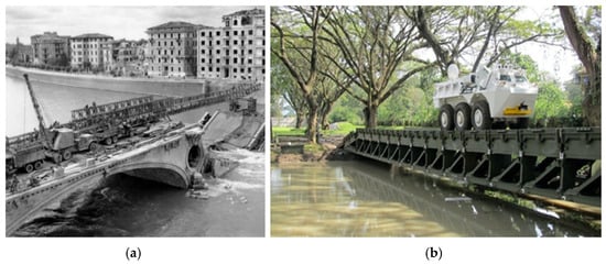
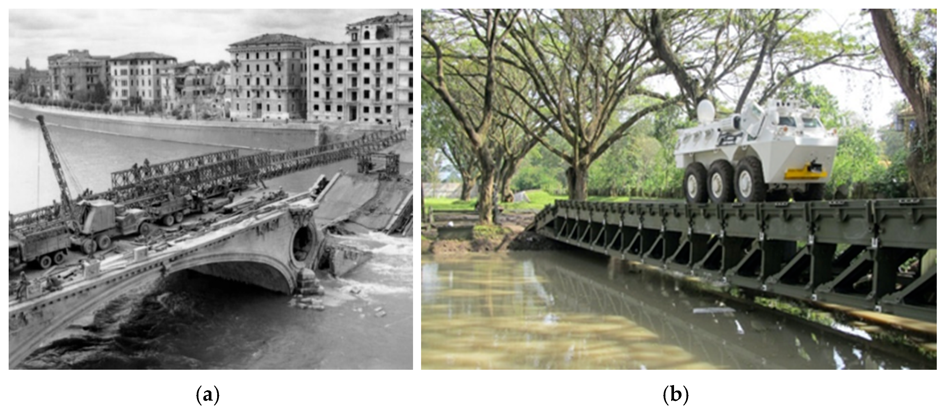
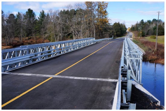
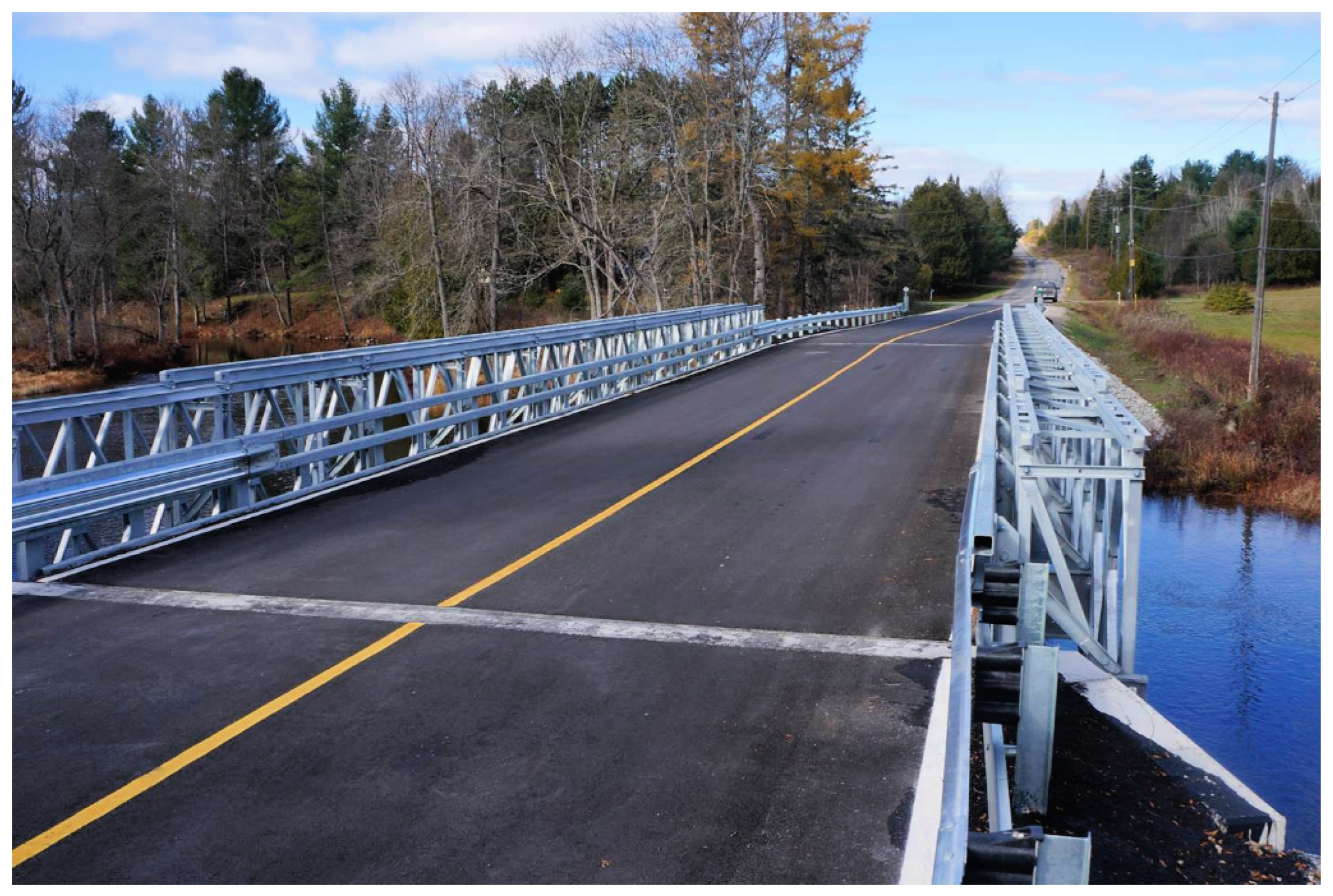
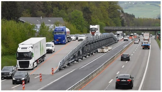
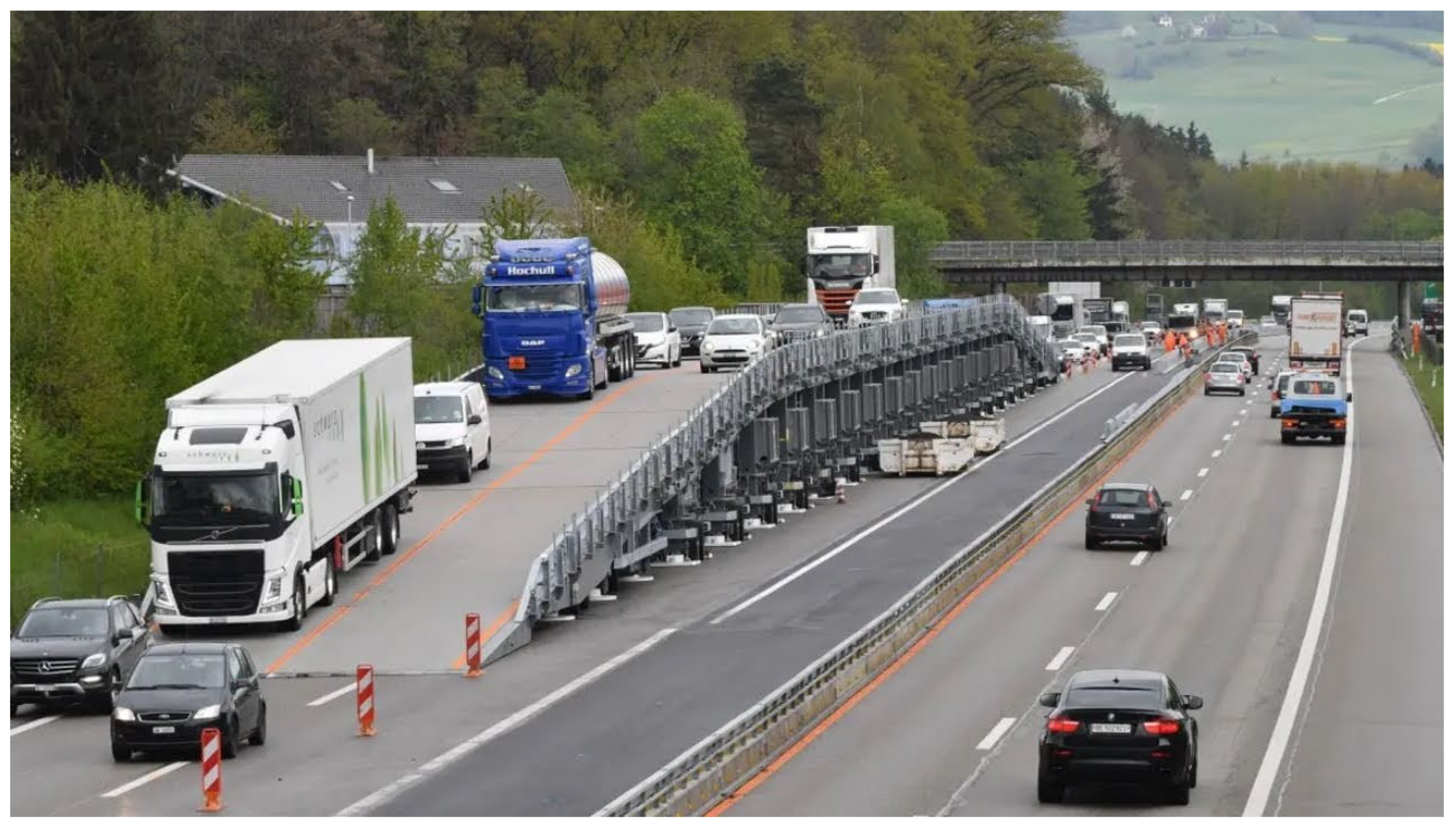
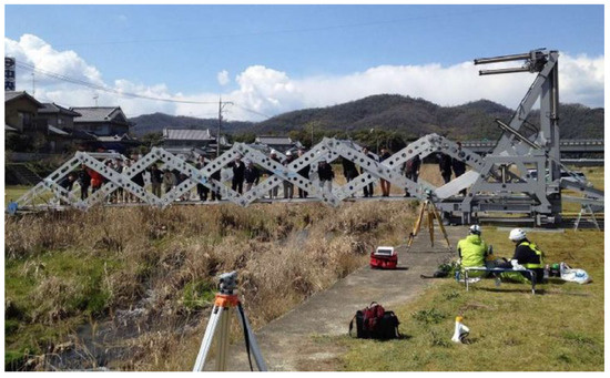
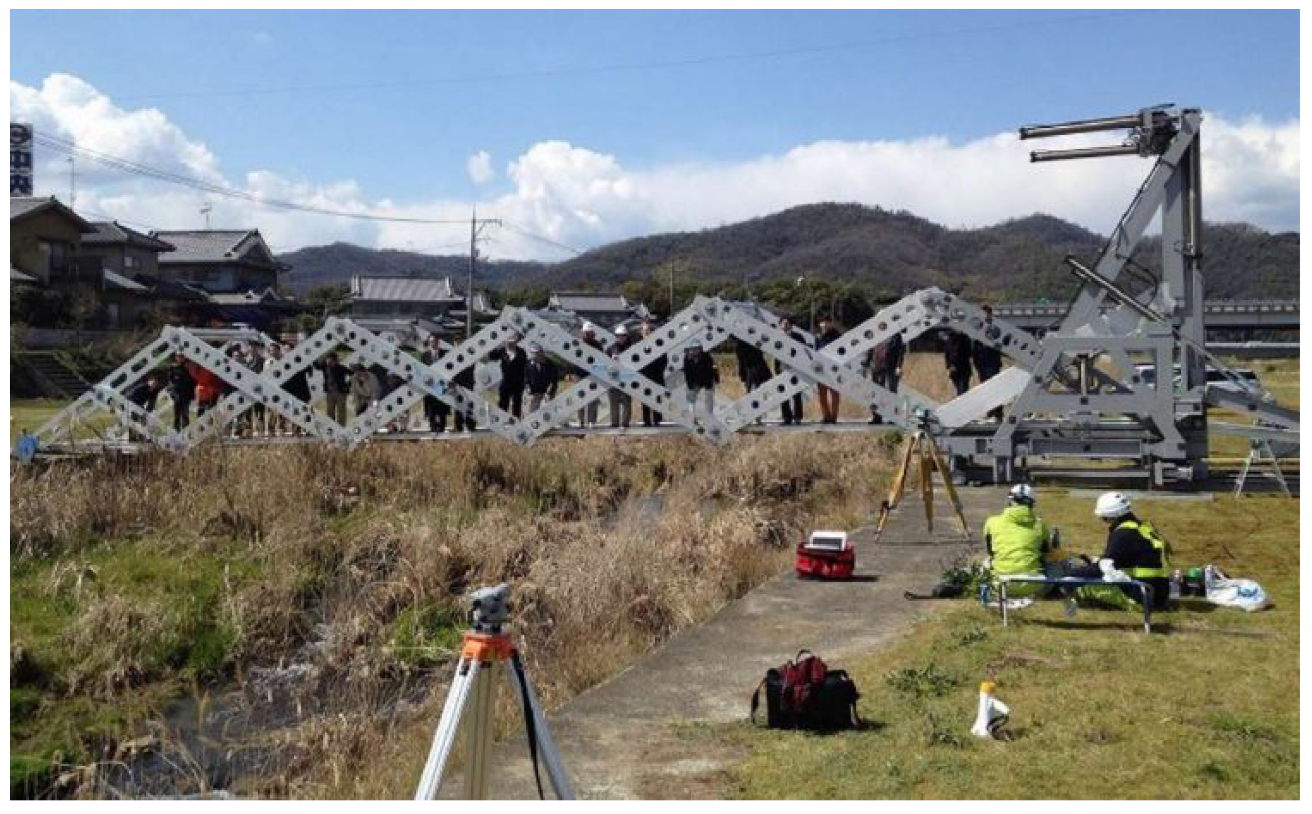
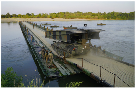
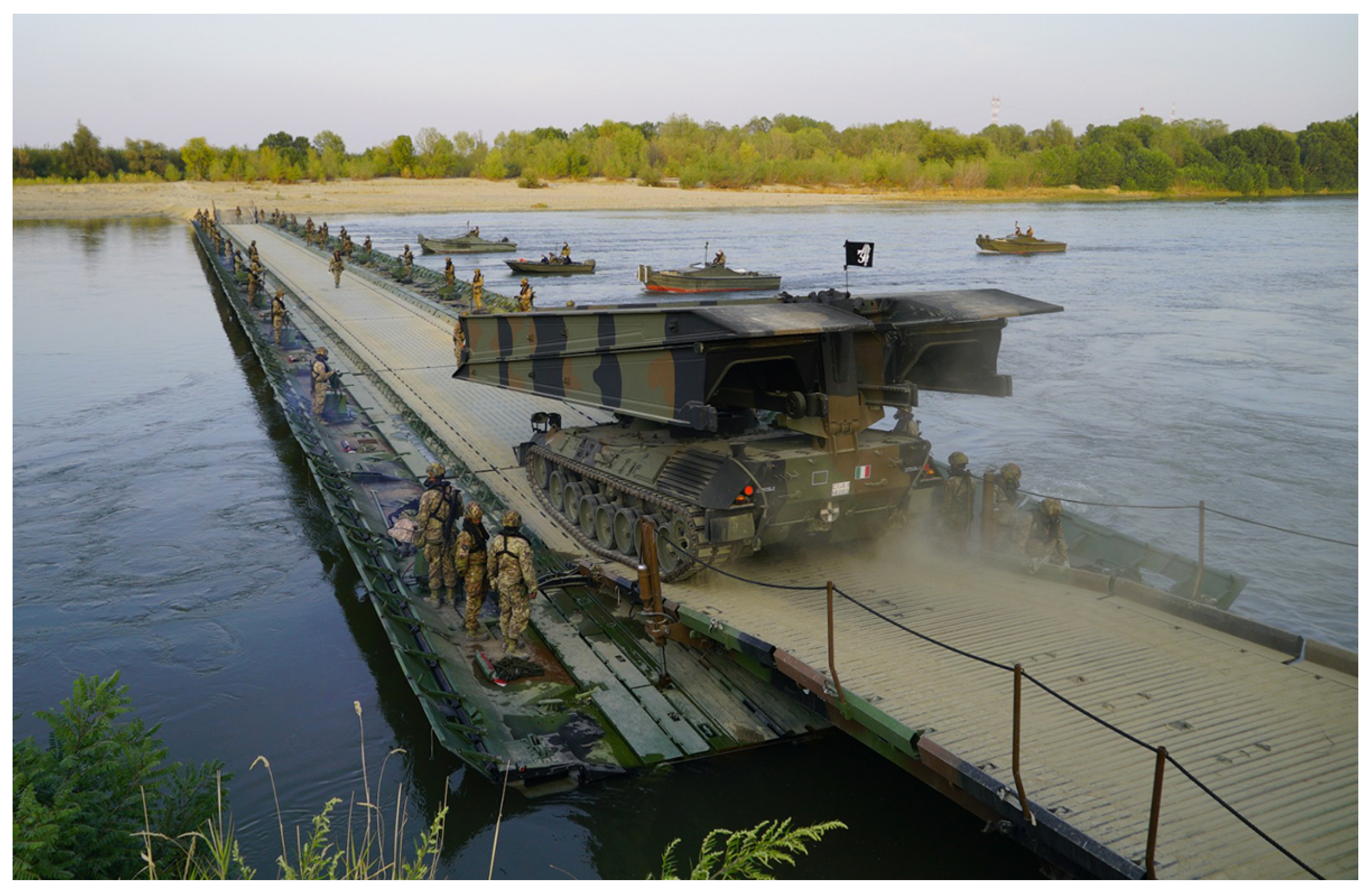
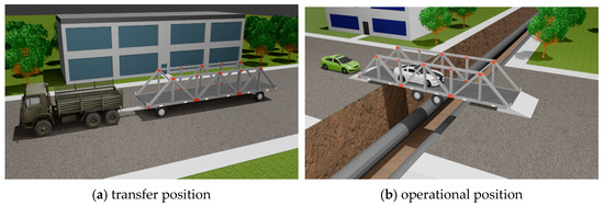
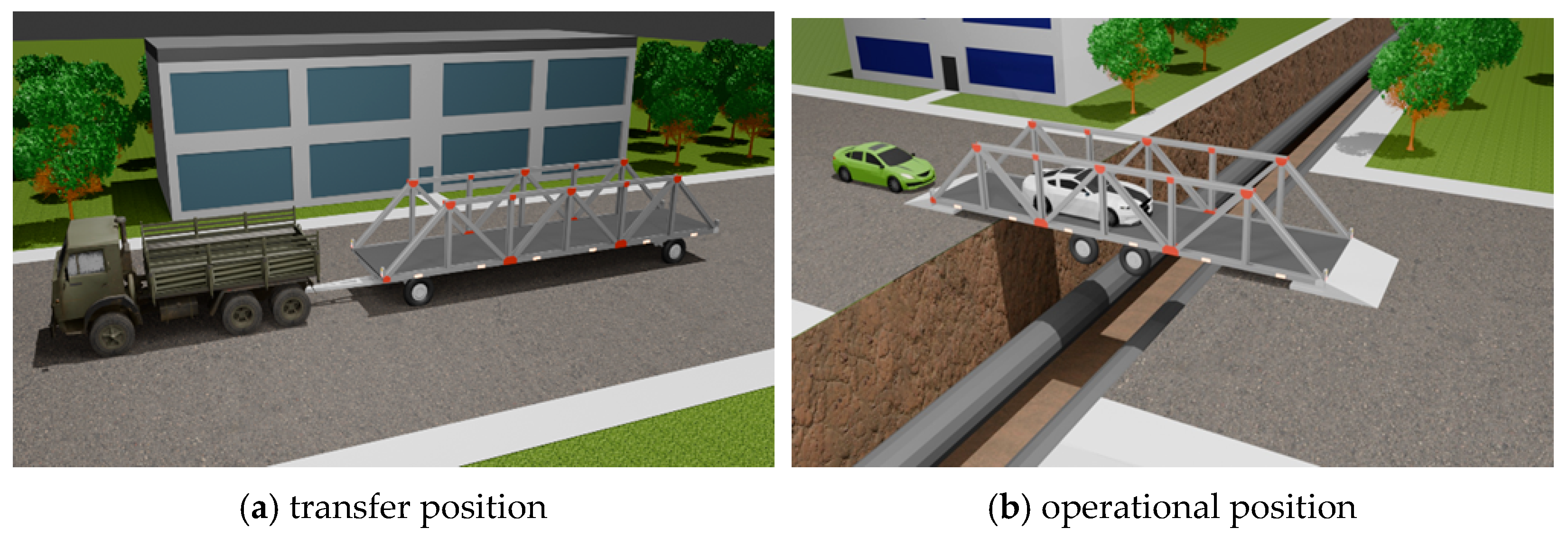
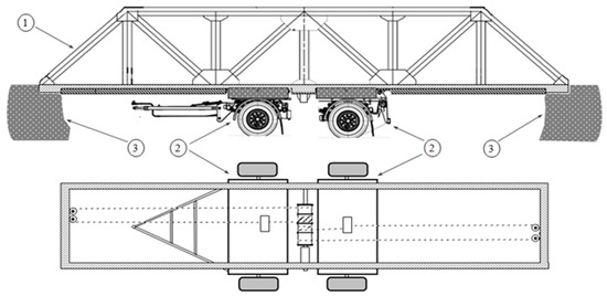
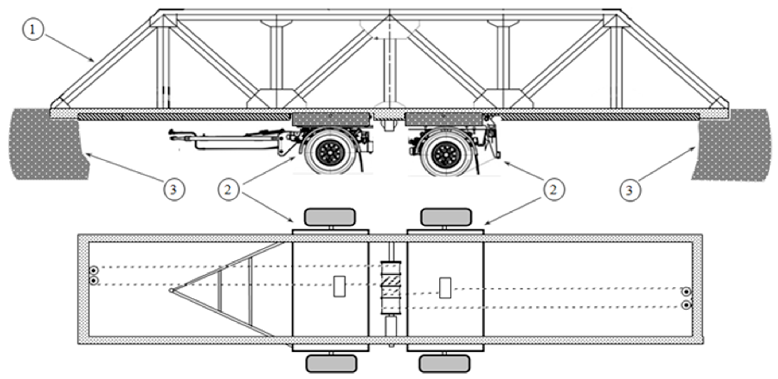
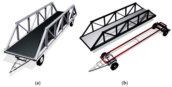
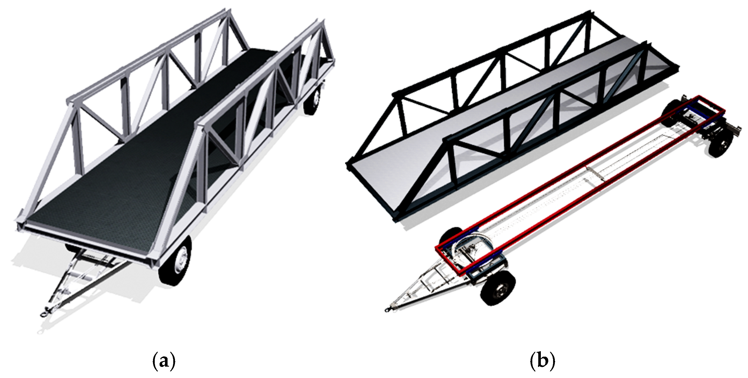
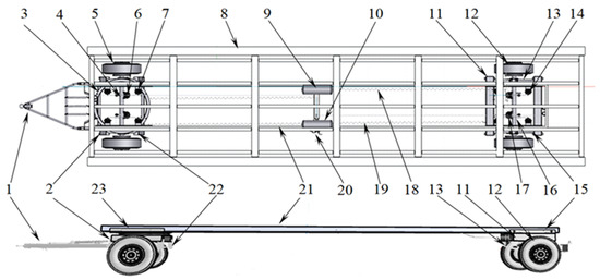
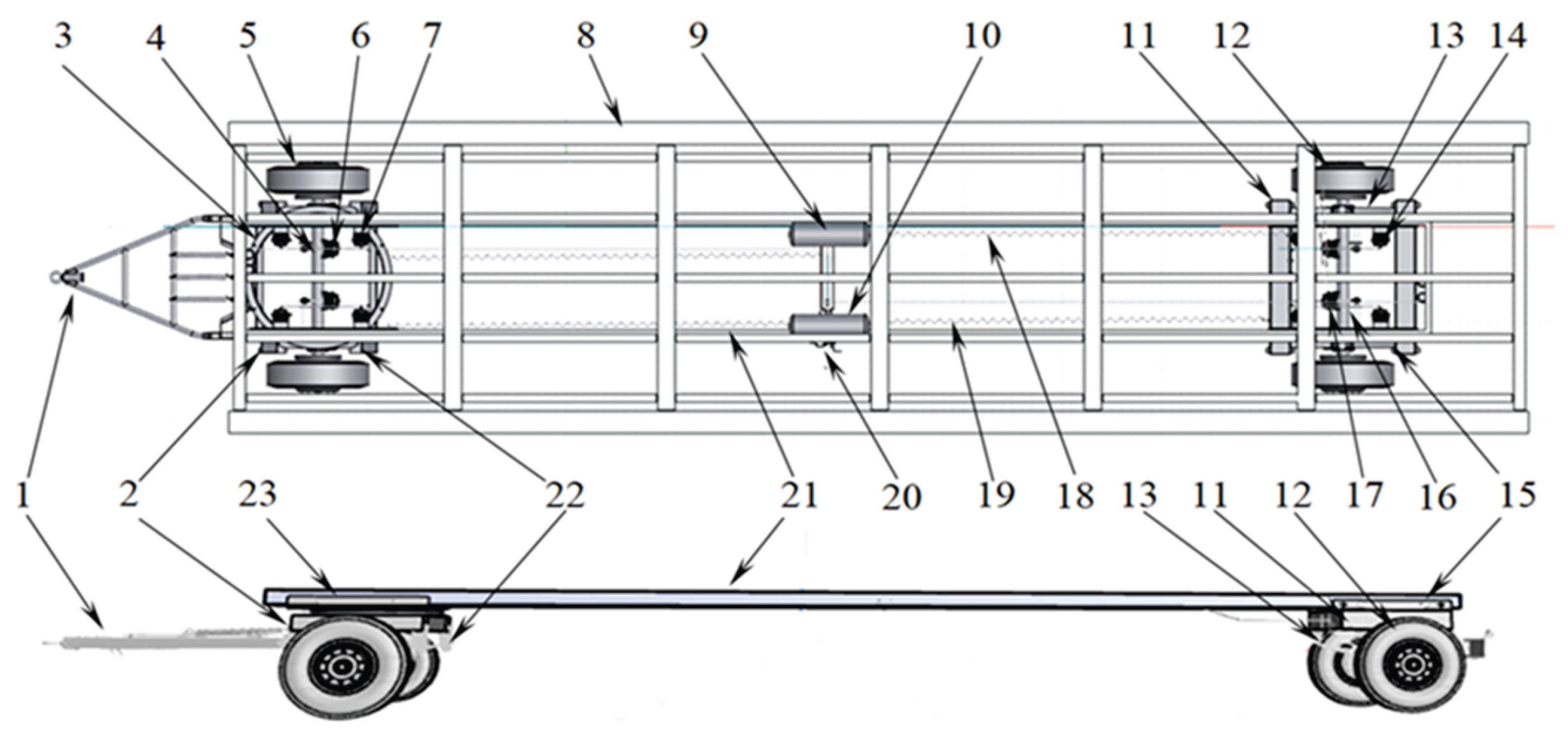
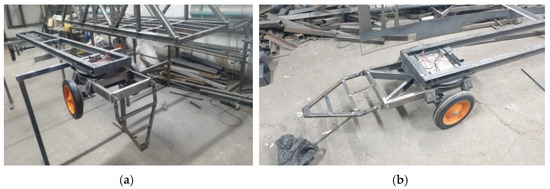
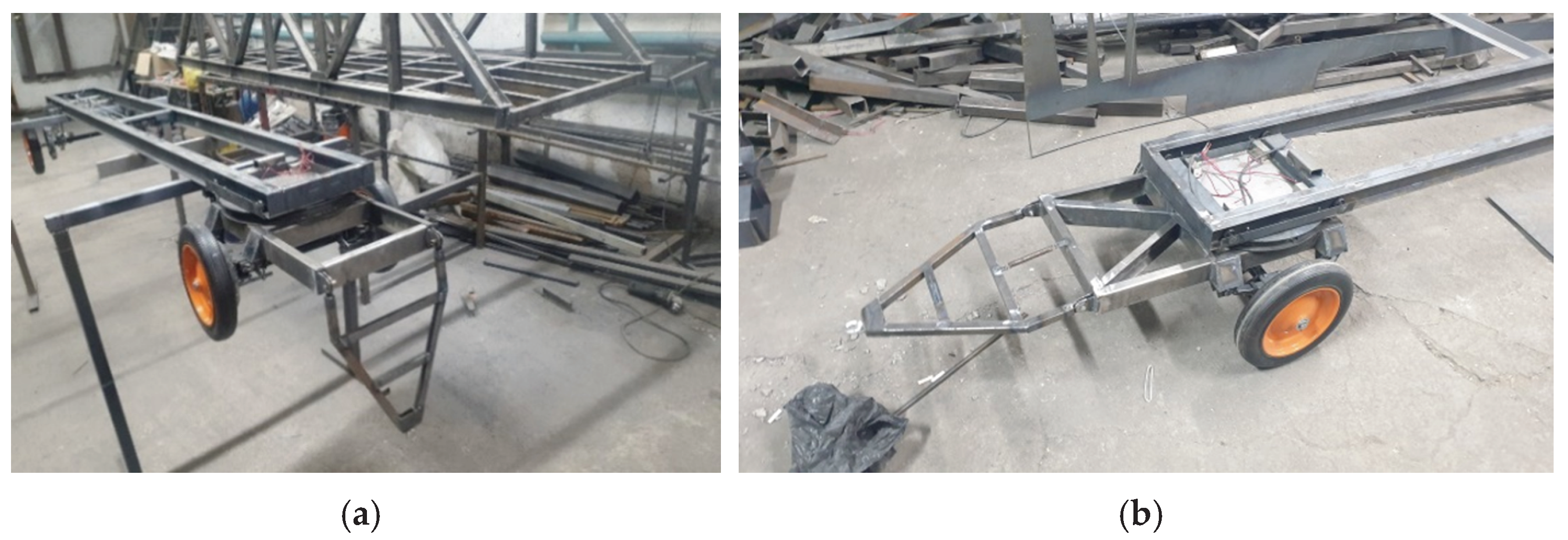
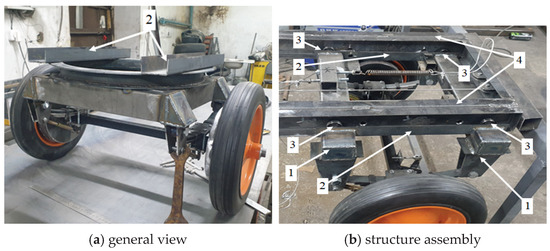
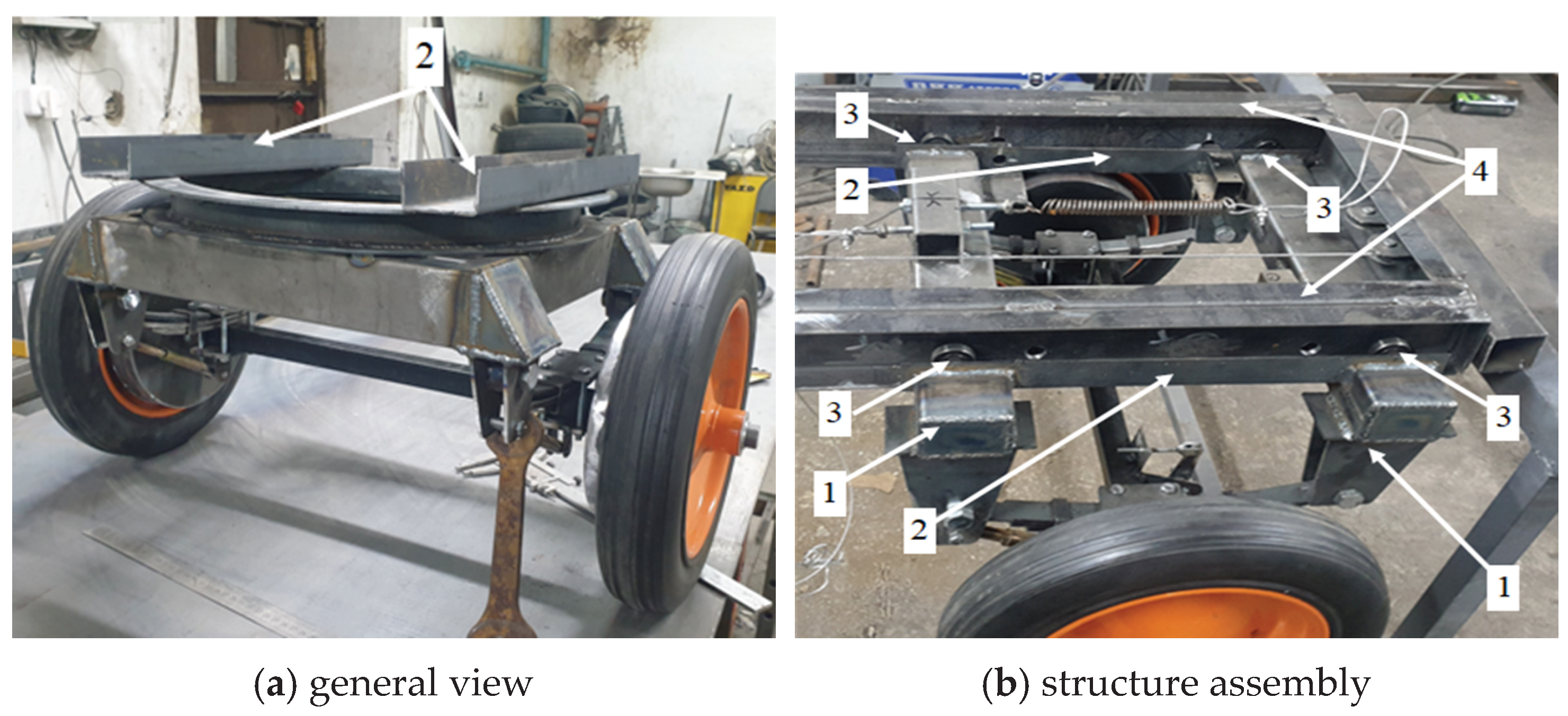
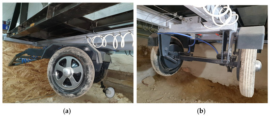
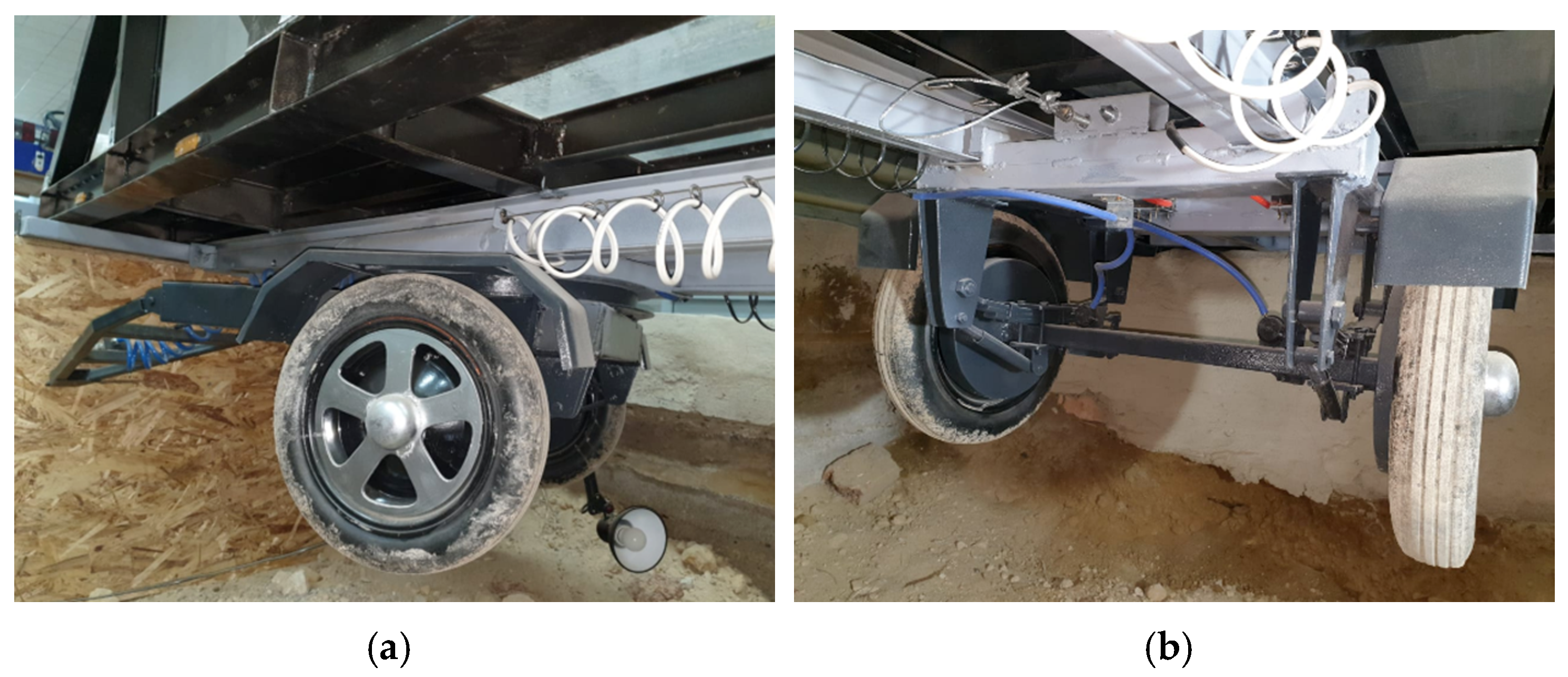
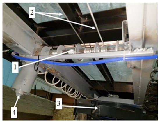
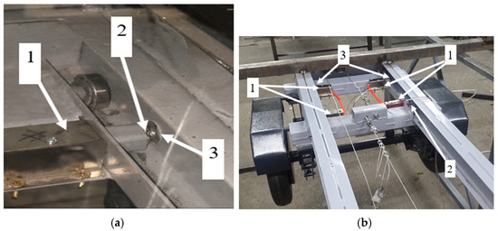
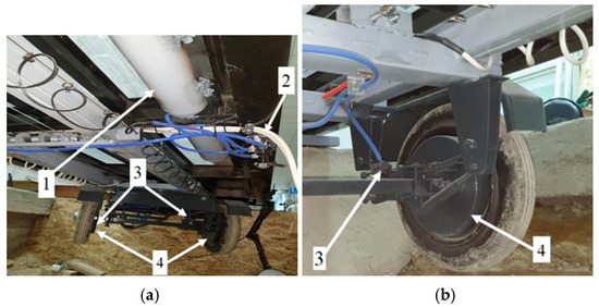
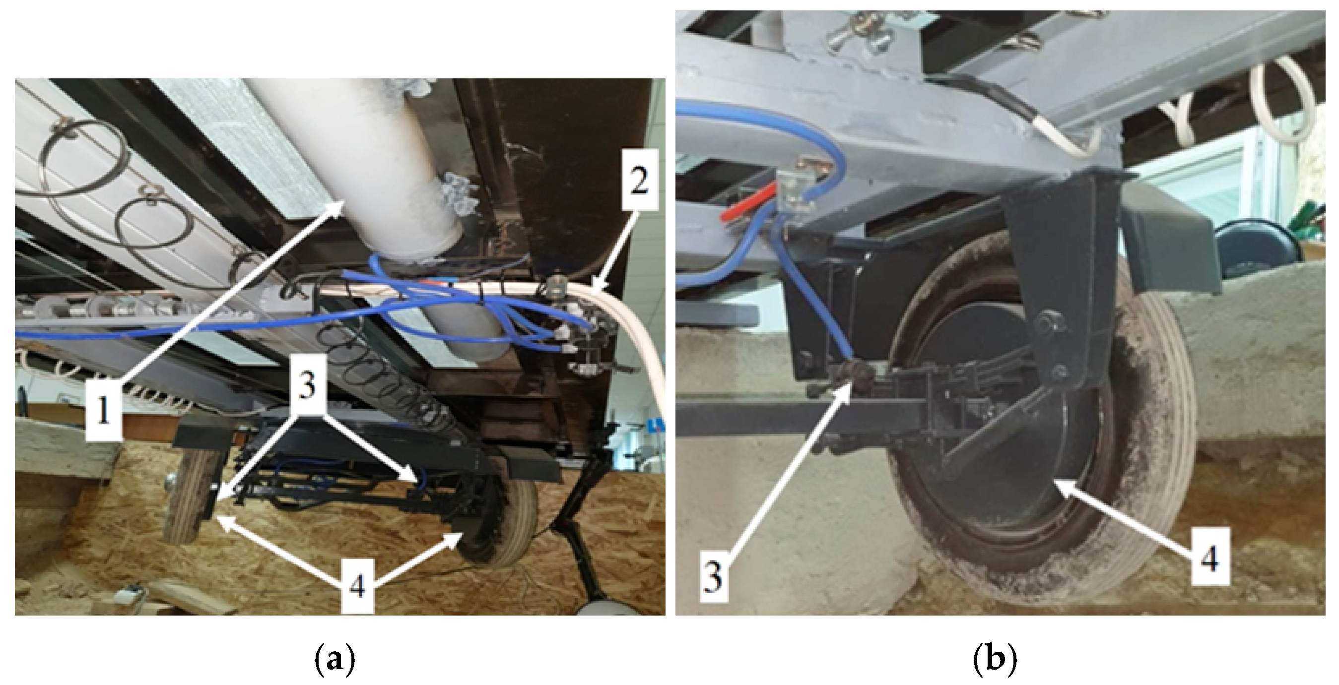
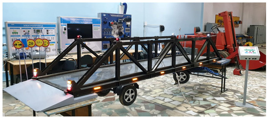
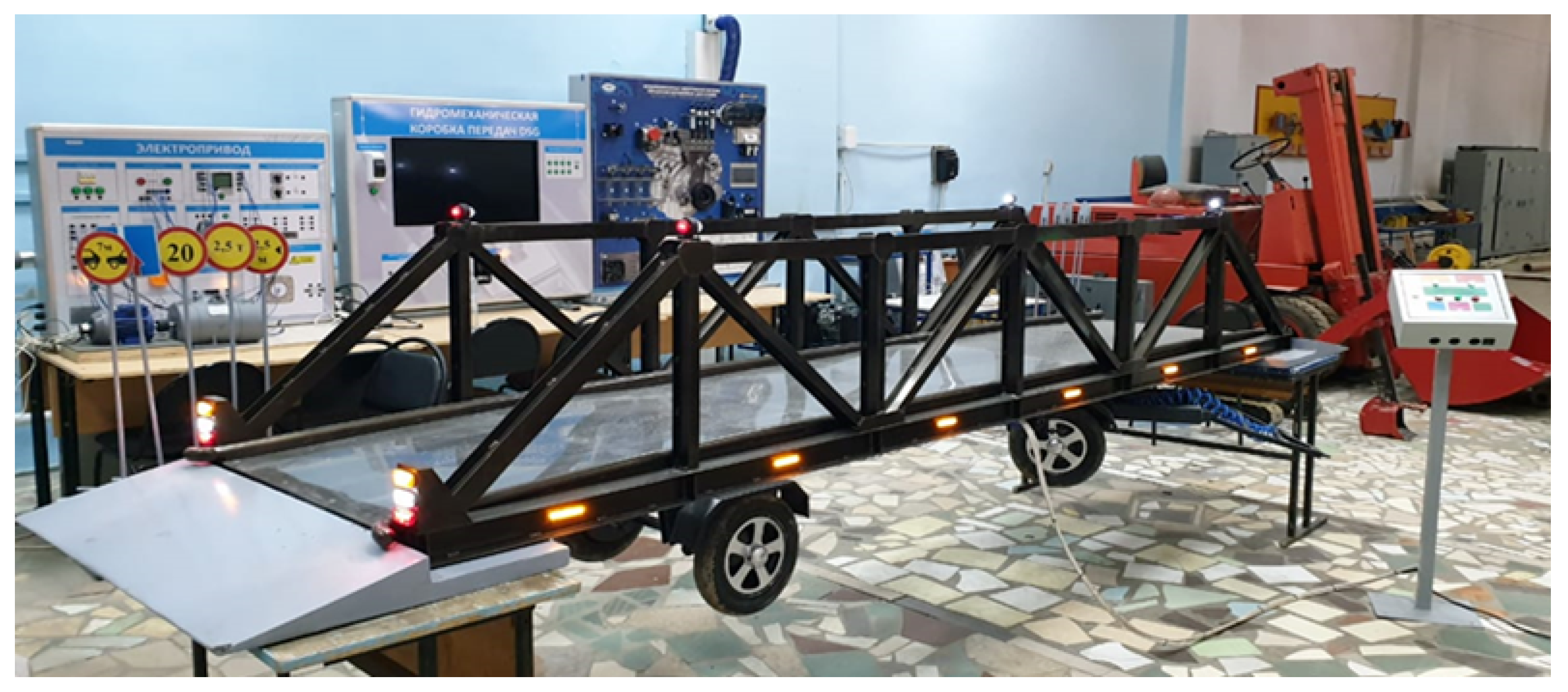
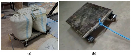
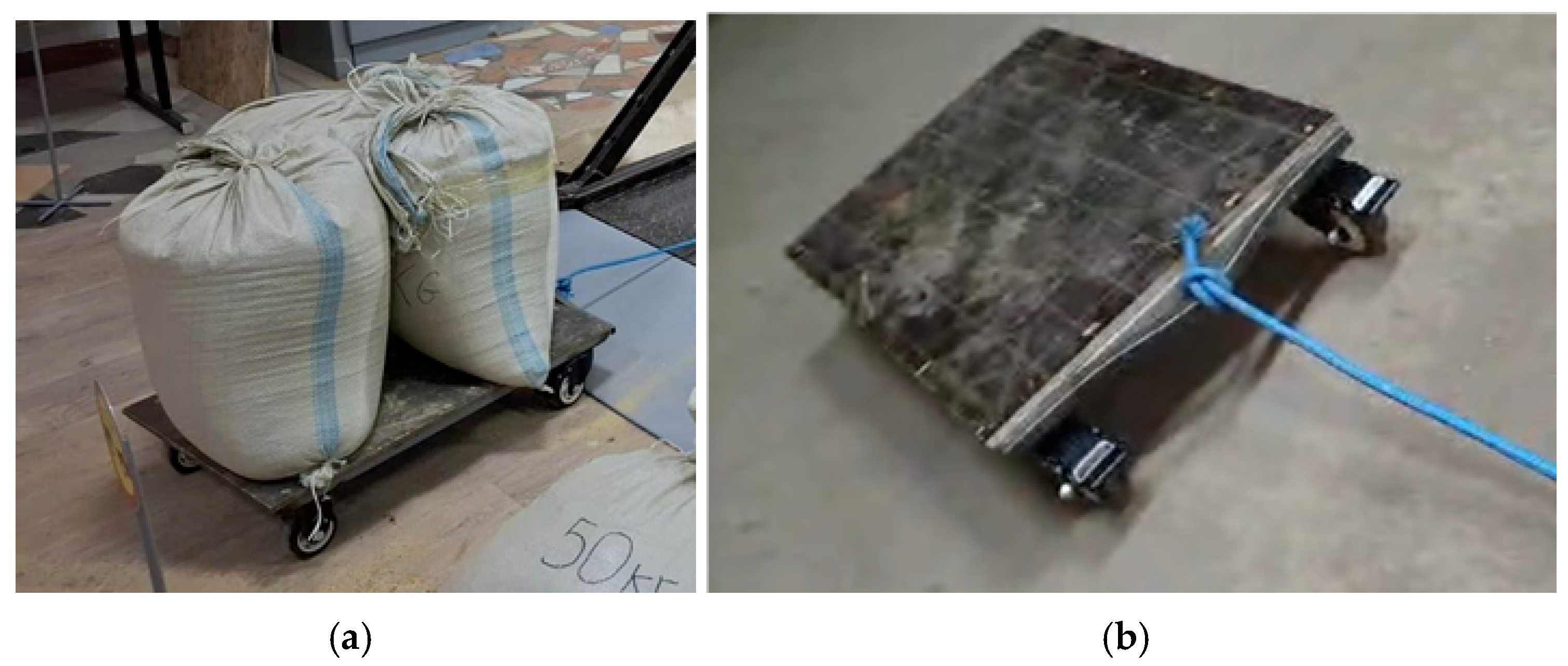
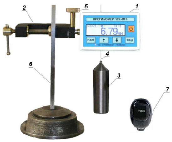
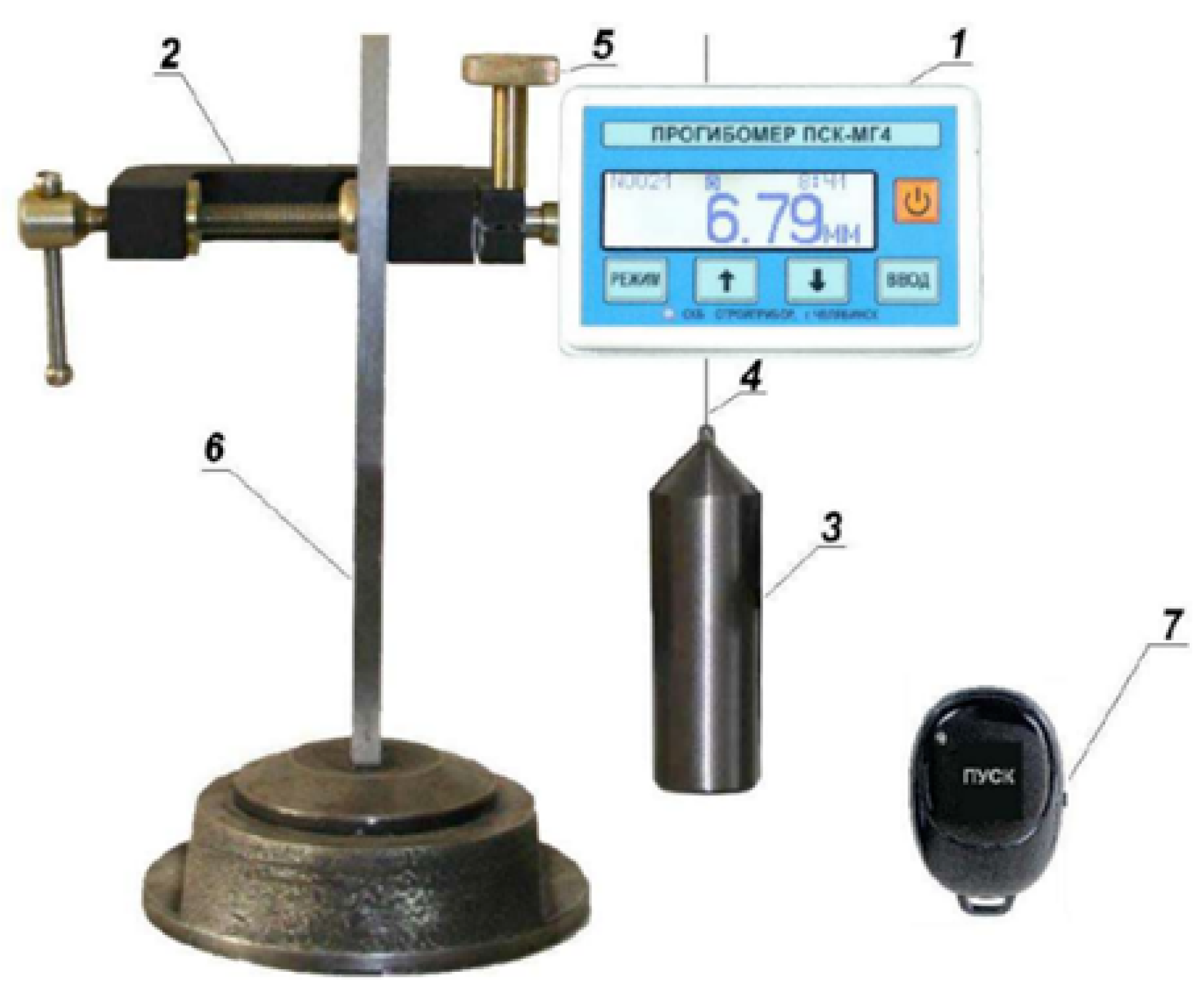
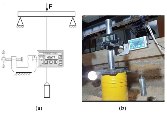
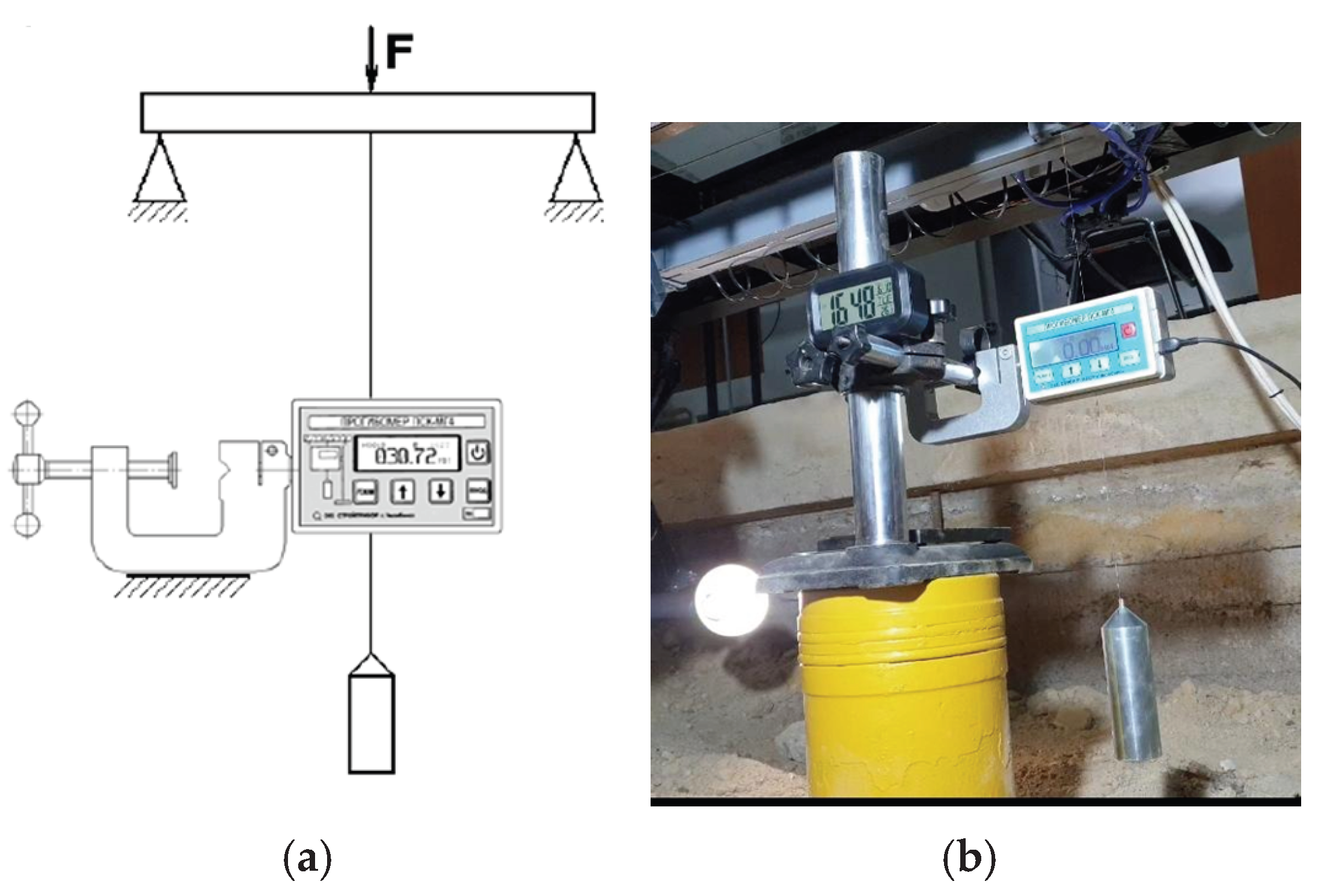
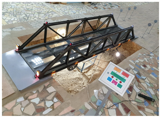
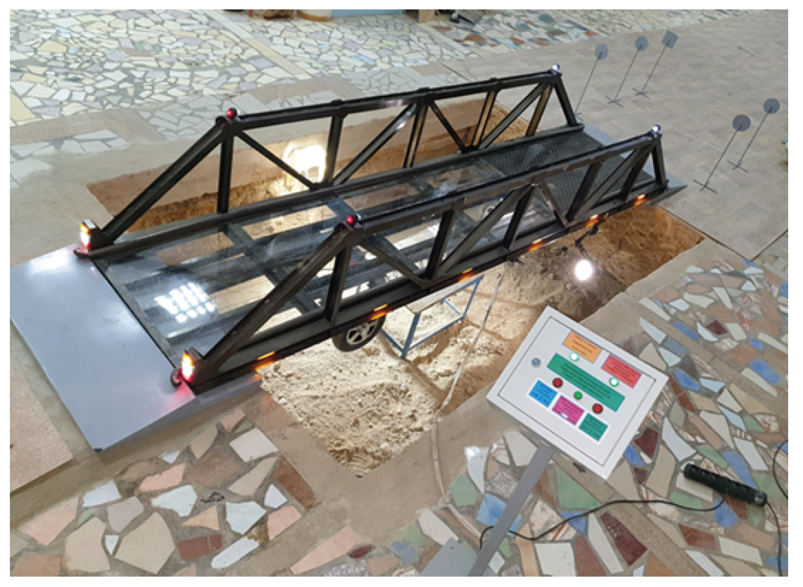
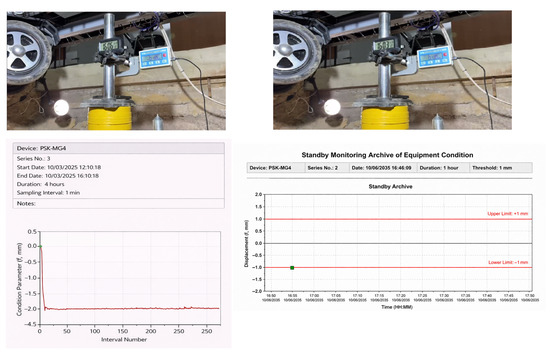
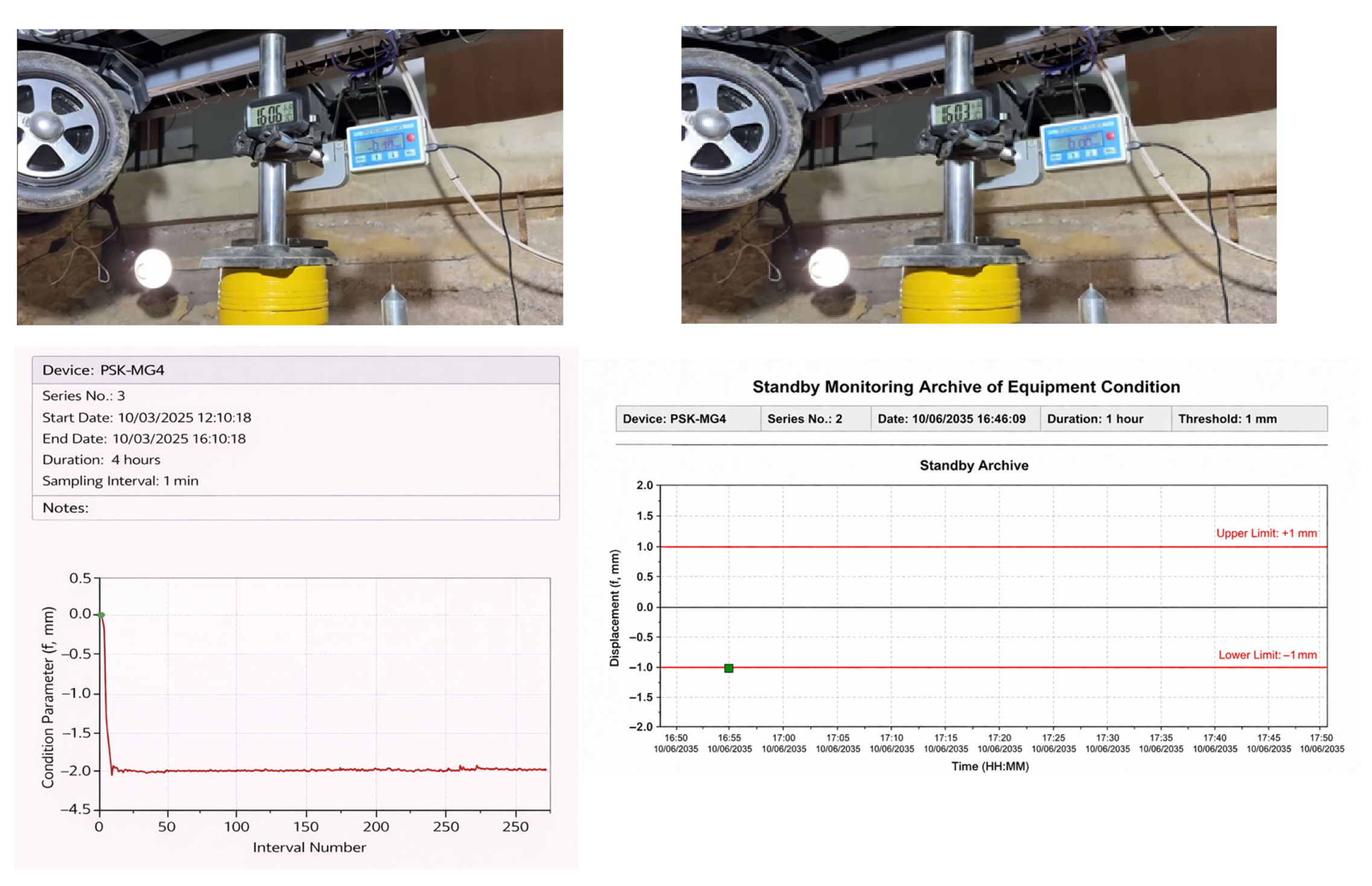
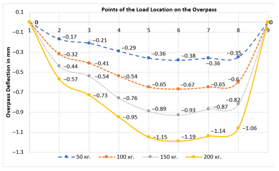
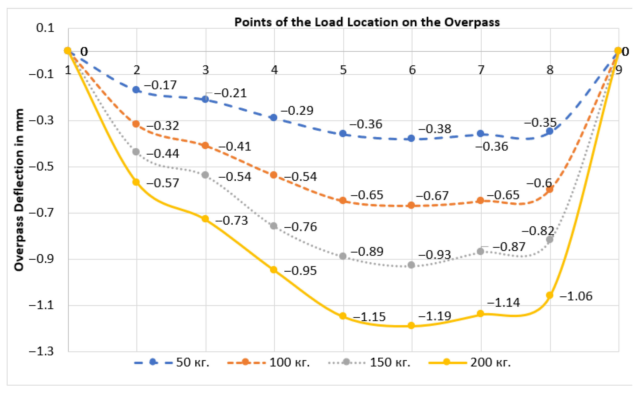
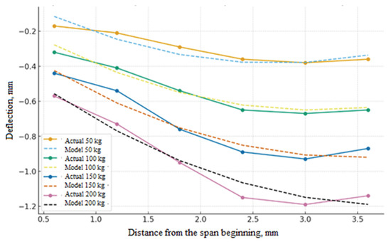
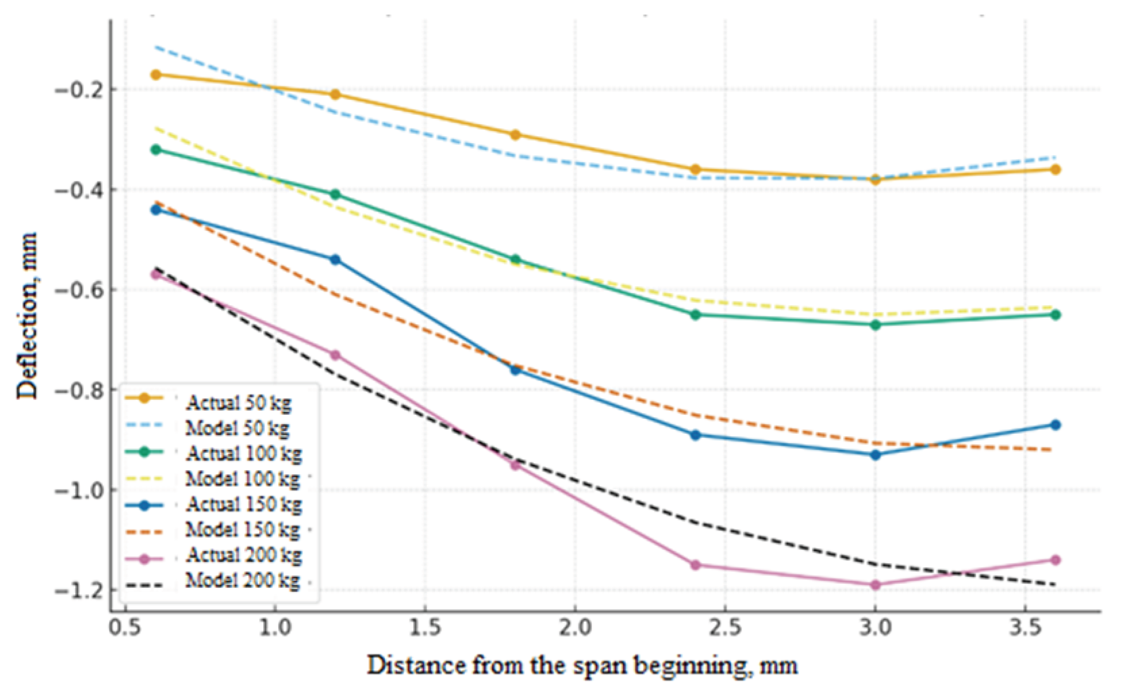
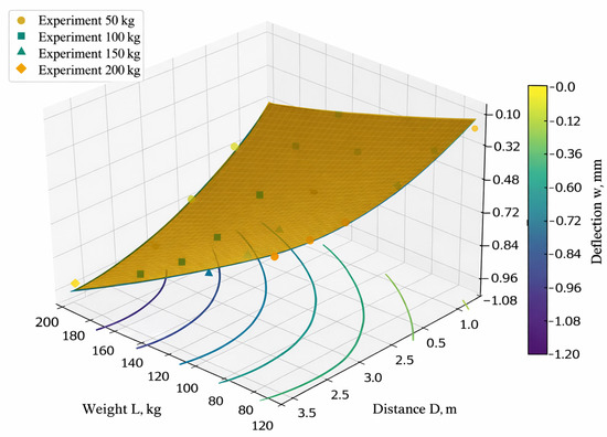
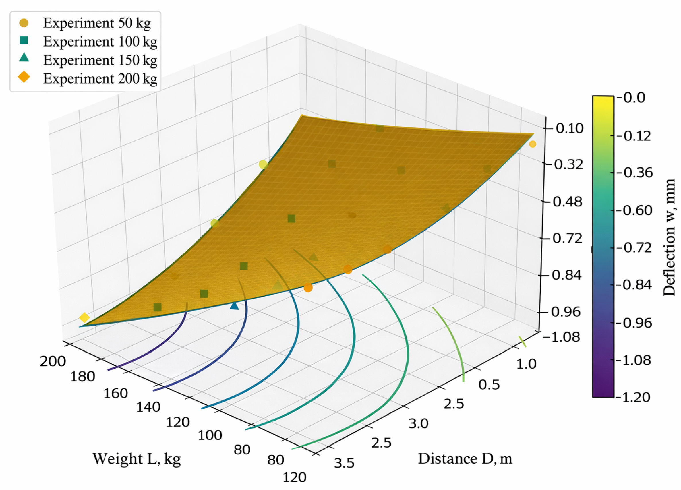
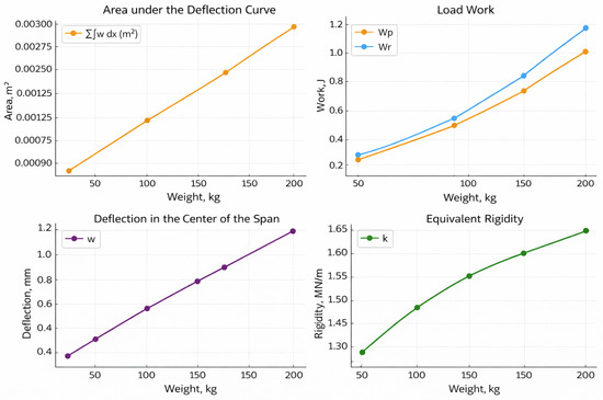
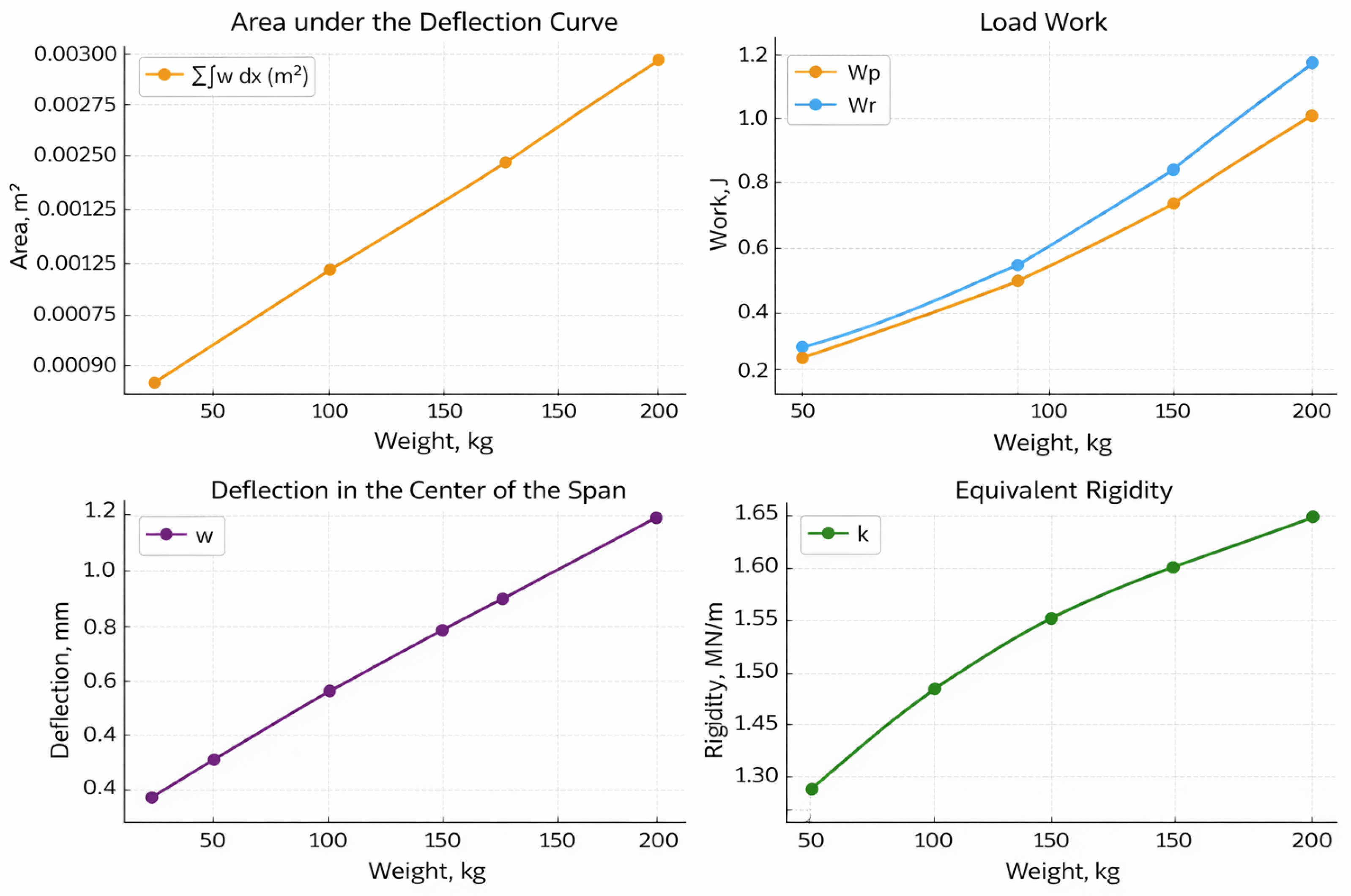

Disclaimer/Publisher’s Note: The statements, opinions and data contained in all publications are solely those of the individual author(s) and contributor(s) and not of MDPI and/or the editor(s). MDPI and/or the editor(s) disclaim responsibility for any injury to people or property resulting from any ideas, methods, instructions or products referred to in the content. |
© 2026 by the authors. Licensee MDPI, Basel, Switzerland. This article is an open access article distributed under the terms and conditions of the Creative Commons Attribution (CC BY) license.