1. Introduction
The pyramid is an elemental and popular shape in both nature and artificial structures due to its high stability. It has been regarded as one of the most basic elements for designing structures throughout engineering history. Some recent reports have been found in the research [
1,
2,
3,
4]. Deployable designs expand their application scope with deformation capacity and low storage requirements, especially in space supporting structures, such as research on antennas [
5] and masts [
6,
7,
8,
9].
Different from existing designs featuring rigid edges [
10,
11,
12,
13,
14], this paper presents a fast-self-deployable design of a lightweight pyramid with flexible edges. These flexible edges can be coiled and stored in a small space and have water-drop shapes.
It is worth emphasizing that the optimization of rod-like and shell-type systems is a widely established engineering practice with a broad range of applications. Representative examples range from large-scale mechanical engineering, such as the practical design of lattice cell towers on compact foundations [
15], to the development of full-strength elastic element sections with open shells [
16], and even delicate biomechanical problems like the analytical modeling of implant-supported overdentures [
17]. Placing our deployable design within this broader context highlights the universal necessity of efficient structural folding and energy storage.
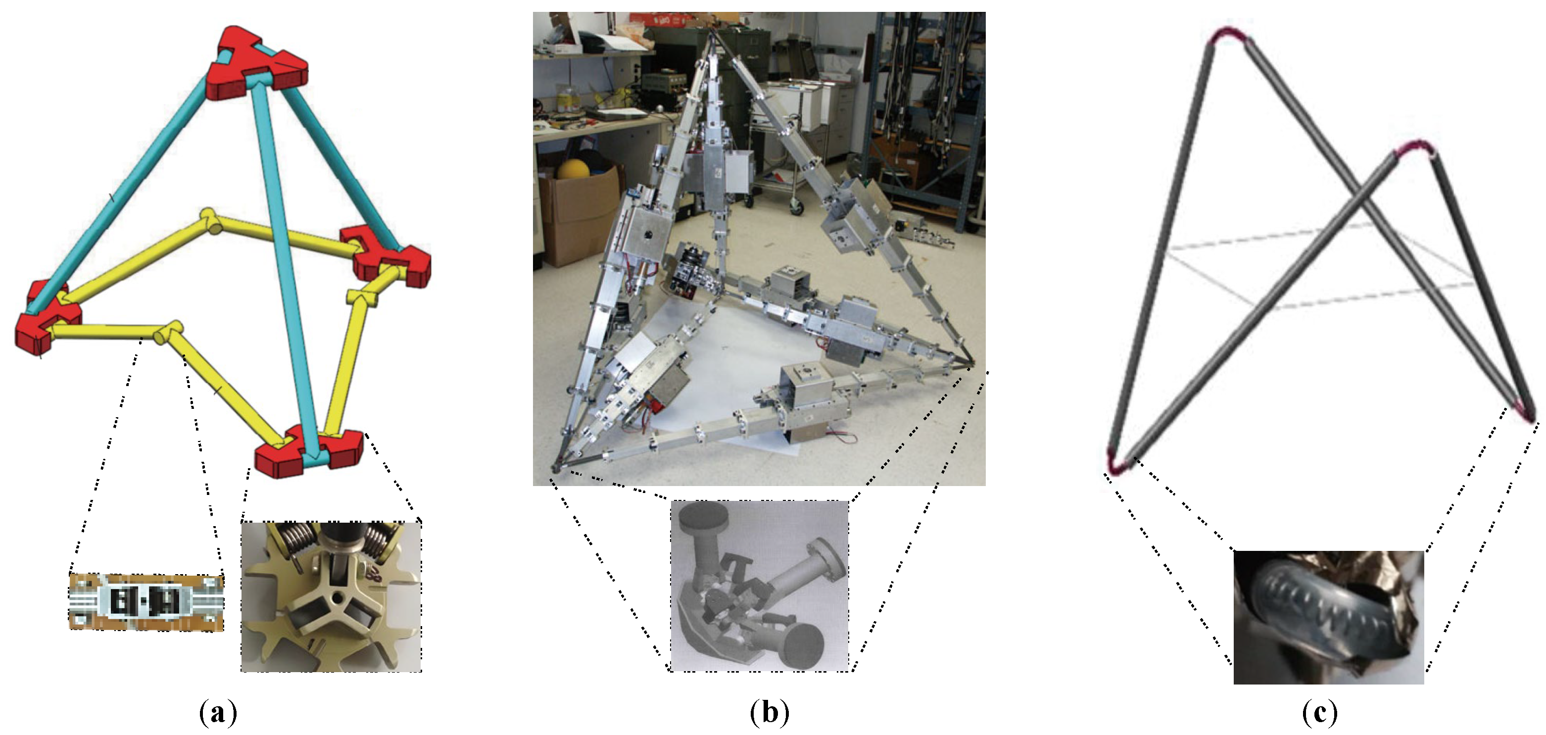
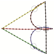
Some applications of deployable rigid pyramids are illustrated in
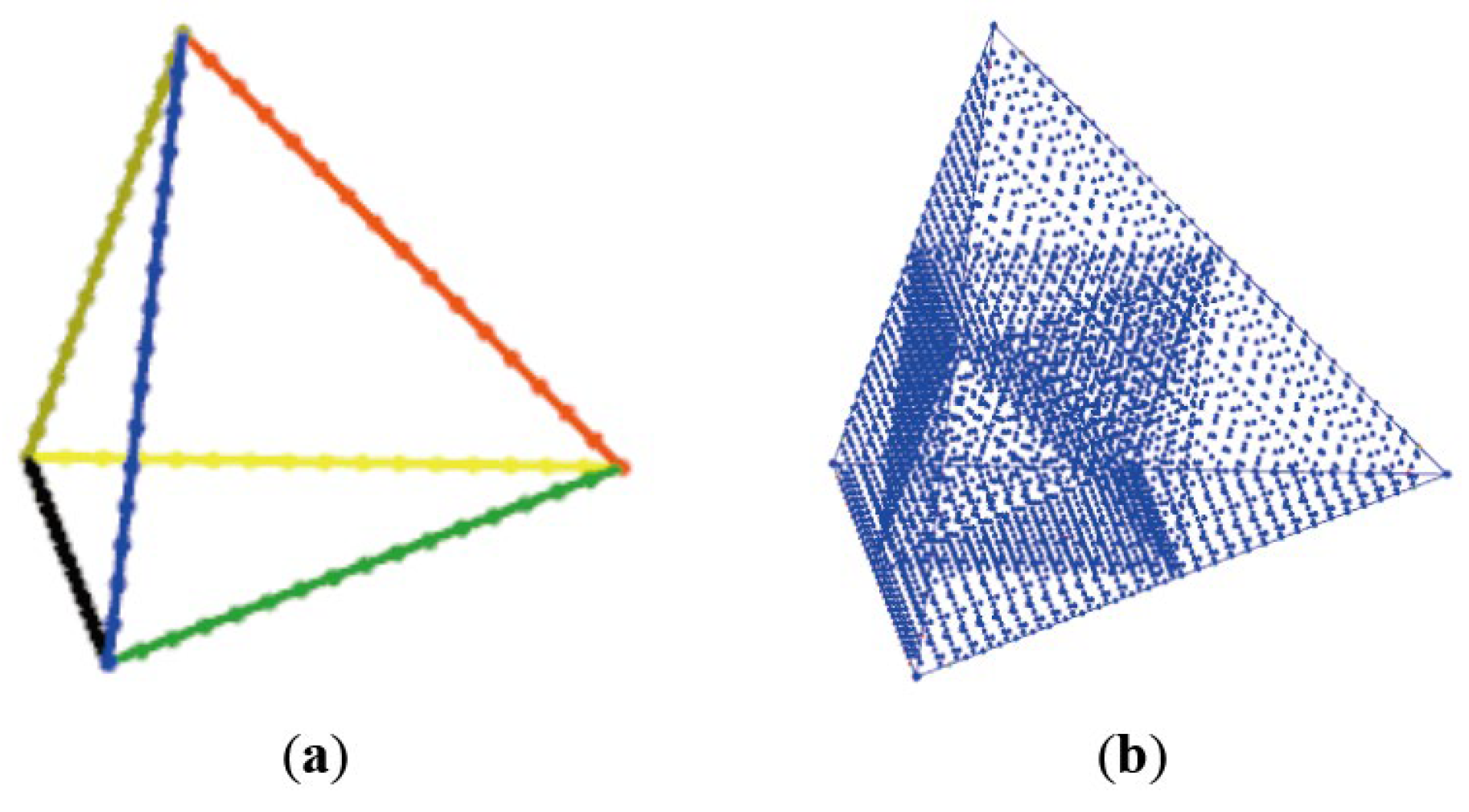
Figure 1, along with graphics of basic pyramid units, connector details, and the assembly of several pyramids. As shown in
Figure 1a, Han et al. [
10], Zheng et al. [
11] and Wu et al. [
18] set butt hinges at the bottom-edge centers to fold the pyramid. Torsion springs were placed in the edge hinges and vertex hinges to drive the unfolding process. The resulting assembly of numerous pyramids can serve as support structures for deployable aeronautical antennas.
Figure 1b depicts the deformable pyramid design with telescopic edges by Curtis et al. [
13]. Electric motors were placed at the edge centers to power the contraction and expansion motions of the edges, and the assembly of several pyramid units was used for space exploration robotics.
In
Figure 1c, a variation in the edge-folding mode was presented by Bettini et al. [
14]. There, two edges of the pyramid were eliminated, and the remaining four edges were split into two groups to form two V-shapes for folding. The deployment forces all came from the spring forces at the vertices, and the pyramid was not complete. As a result, although less stable than a complete pyramid, the assembled structure was lighter and could be used for small and light antennas. In the rigid pyramid designs, the deployment energies are centrally stored in the connectors.
To the best of the author’s knowledge, the deployment of flexible pyramids has not yet been reported in the literature. However, similar longeron-coiling concepts have been widely adopted in the compaction of flexible prisms [
19,
20,
21,
22,
23,
24].
As shown in
Figure 2a by Liu et al. [
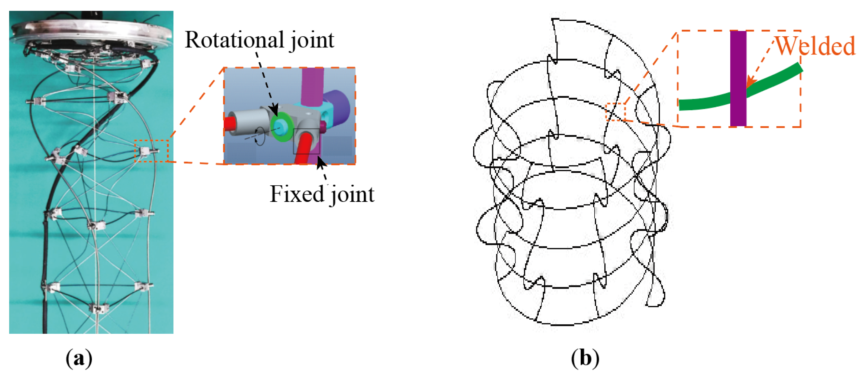
25], a classic deployable prism is composed of flexible longerons, flexible transverse battens, diagonal ropes, and vertex connectors. In the deployed state, the diagonal ropes are tensioned to divide a basic section of the prism into several pyramids (with shared edges) to keep the configuration stable. During the compaction process, the long, straight longerons are coiled into cylindrical helices to stack up, with the diagonal ropes relaxed and the transverse-batten triangles rotating horizontally. The vertex connectors depicted in
Figure 2a are specially designed for this motion pattern.
Figure 2b illustrates a deployable prism proposed by Murphey [
23], which was made up of several longerons and two helical transverse battens with welds between them. When compacting, the two helical transverse battens rotate in opposite directions along their respective line-length-directional axes, and then the longerons are coiled into multi-“S”-shapes by compressing the spring-like battens.
Compared with rigid pyramid designs, the deployment energy of flexible prisms is stored in the coiled longerons. However, the longeron-coiling-based designs are only applicable to truss structures with slender and straight shapes, i.e., prisms.
For flexible truss structures with arbitrary shapes, a coilable design for a single pyramid is required, and similar treatment of each edge is crucial. Silva et al. [
26] recently studied the buckling properties of a flexible pyramidal structure without the bottom edges theoretically, and Liu et al. [
27] studied the buckling in the lateral beams of a coilable mast.
In this paper, a coilable design of a flexible pyramidal truss will be achieved through the water-drop buckling of each edge, and vertex connectors with specific guiding grooves will be designed based on parameter optimization to obtain a controlled self-deployment process of the pyramid.
The remainder of this paper is organized as follows: In
Section 2, the basis of water-drop buckling and deployment is introduced. The analytical solution is deduced and compared with experimental results. By having the edges over-buckled into multi-circles, larger compression ratios are obtained. In
Section 3, geometrically exact beam elements are adopted to calculate the large-deformation dynamics during water-drop buckling and deployment. The formulation and solution of the flexible multibody system are presented. Numerical results are then compared with the deployment experiment data. In
Section 4, a self-deployable pyramidal truss design based on water-drop buckling is proposed. A possible multi-layer pyramid design is also introduced. In
Section 5, a deployable simulation is conducted using the presented beam-on-beam contact formulation. Through simulations, three in-plane equilibria of a pyramid are identified. Considering this phenomenon, an out-of-plane reinforcement is added for the actual deployment design. After all, the pyramid truss is coiled into water drops and then successfully deployed through the flexible multibody simulation. Finally, the conclusions of this study are put forward in
Section 6.
2. Water-Drop Buckling Analysis Basis
In this section, we will offer a detailed description of the fundamentals and properties of water-drop-shaped buckling analysis, establishing the foundation for the subsequent design of flexible self-deployable trusses. This encompasses analytical solutions, experimental verification, and the generation of generalized shapes of water-drop buckling.
2.1. Analytical Solutions
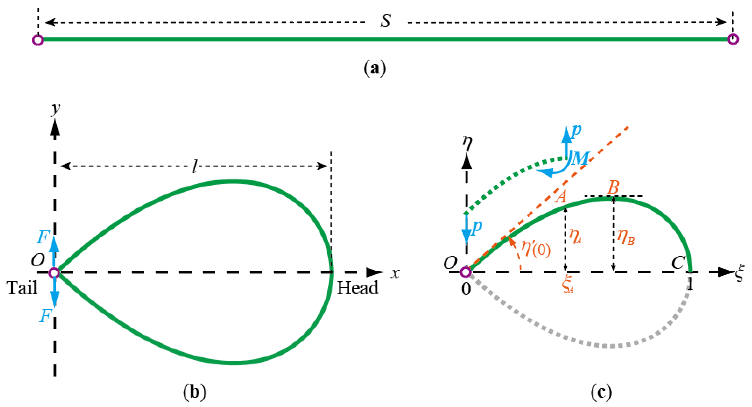
As shown in
Figure 3a,b, a straight beam is bent at one end and then “tied” to the other end, which results in an in-plane “water-drop” buckling under the minimum potential energy.
This water-drop shape is the basic form for coiling more complicated three-dimensional trusses into in-plane shapes. To study its basic properties, a dimensionless Cartesian coordinate system
is set at the tail of the water drop, as shown in
Figure 3c.
By dividing the spatial position coordinates
and
by the water-drop length,
as shown in
Figure 3b, the dimensionless coordinates are given as
wherein
explicitly represents the linear horizontal span of the buckled water-drop,
is the axial coordinate along the water-drop tail to the head, and
is the lateral coordinate.
Due to the up-down symmetry, only the upper part of the buckling shape is considered. The buckled curve is then written as
Because the point coordinates are
in
Figure 3c, the curve at point
is perpendicular to the
axis, and no moment is acting at point
with a simple joint, the boundary conditions are therefore
Let the joint force at point
from the lower part be
, the balancing moment is then
for a point with a moment arm
, the curvature is
. By defining the equivalent curvature with respect to the coordinate
as
and together with the Euler–Bernoulli beam theory [
28], we have
Integrate for
ξ once by using the transform
and the boundary condition
to yield
or presented in integral form as
wherein
is an arbitrary point on the upper part of the curve. Define the dimensionless arc length
as
wherein
is the initial length of the beam. The dimensionless arc length can be calculated by
Equation (6) suggests that
reaches its maximum at
and the half-width of the water-drop is then
Therefore, the slope at point
is
The dimensionless stress in the buckled beam is defined as
wherein
is the real stress in the buckled beam,
is the elastic modulus of the material,
is the section radius,
is the moment of inertia of the cross-section,
is the dimensionless arc length, and
is the real arc length.
Therefore, the “water-drop” buckling shape has a linearly increased curvature and internal torque with the abscissa
,
as shown in
Figure 3b,c. It can be seen that the maximum stress
occurs at the point
with
, and this generates
The dimensionless analytical solution generates an invariant solution for the water-drop buckling shape of a straight beam bent with simple joints at its ends. That is, regardless of the material used, the beam length, and the section radius, as long as it is within the elastic range, the water-drop buckling has the same shape.
It should be noted that the Euler–Bernoulli beam theory is adopted here solely for the analytical derivation of the dimensionless 2D invariant. This simplification is justified by the extremely high length-to-diameter ratio of the rods used in this study, which renders shear deformation negligible under static conditions. For subsequent highly nonlinear 3D deployment processes involving large complex curvatures and finite rotations, geometrically exact beam elements (GEBEs) [
29] are utilized.
2.2. Experiment Verification
Notice that, for a given point such as the head point
, Equation (7) is an algebraic equation with only a single unknown parameter
, and it is solvable. The algebraic equation to be solved for parameter
is
Due to the integration in Equation (14), we solved it numerically using a shooting method. Then, we obtained the solution for a standard water-drop buckling shape as
The solution (15) draws the characteristics of the water-drop buckling shape:
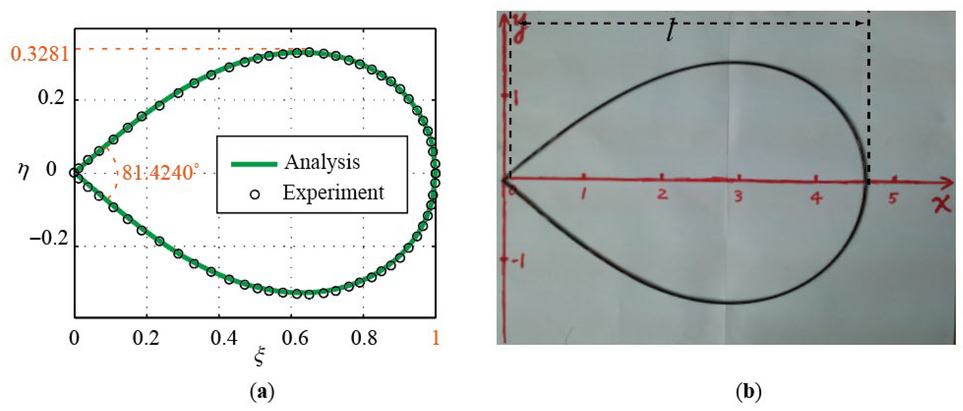
The equivalent curvature is always 3.3045.
The straight beam length is 2.5537 times the water-drop length, which means the in-plane compress ratio is 2.5537.
The widest position is at a distance of 0.6283 (which is near the golden ratio 0.618) of the length from the tail.
The water-drop width is 0.6562 times its length.
The tail angle is 0.8605 rad or .
Moreover, what can be obtained from Equation (13) is the following.
The maximum stress occurs at the water-drop head, with a value of , wherein is the water-drop length, is the Young’s modulus, and is the rod diameter.
With the solution (15), the shape configuration obtained by solving Equation (7) is plotted in
Figure 4a. For comparison, a physical experiment is also conducted, and the results are plotted in
Figure 4b, where a carbon-fiber straight beam is bent into a water-drop shape with the ends simply tied together. The results are in good agreement with each other.
2.3. Generalized Water-Drop Shapes
Inspired by the research by Ding et al. [
30], which studied the buckling properties of water-drop-shaped pressure hulls with various shapes, we considered generalized water drops to obtain more properties of the beam buckling.
Generalized water-drops will be generated when the beam ends are joined with non-zero distances or when more constraints are added. By setting a non-zero value to in Equation (7), the ends are constrained with a distance. Solving Equation (7) generates variant values of . Equation (7) can be solved when , and the widest point is only available for .
With the variation in equivalent curvature
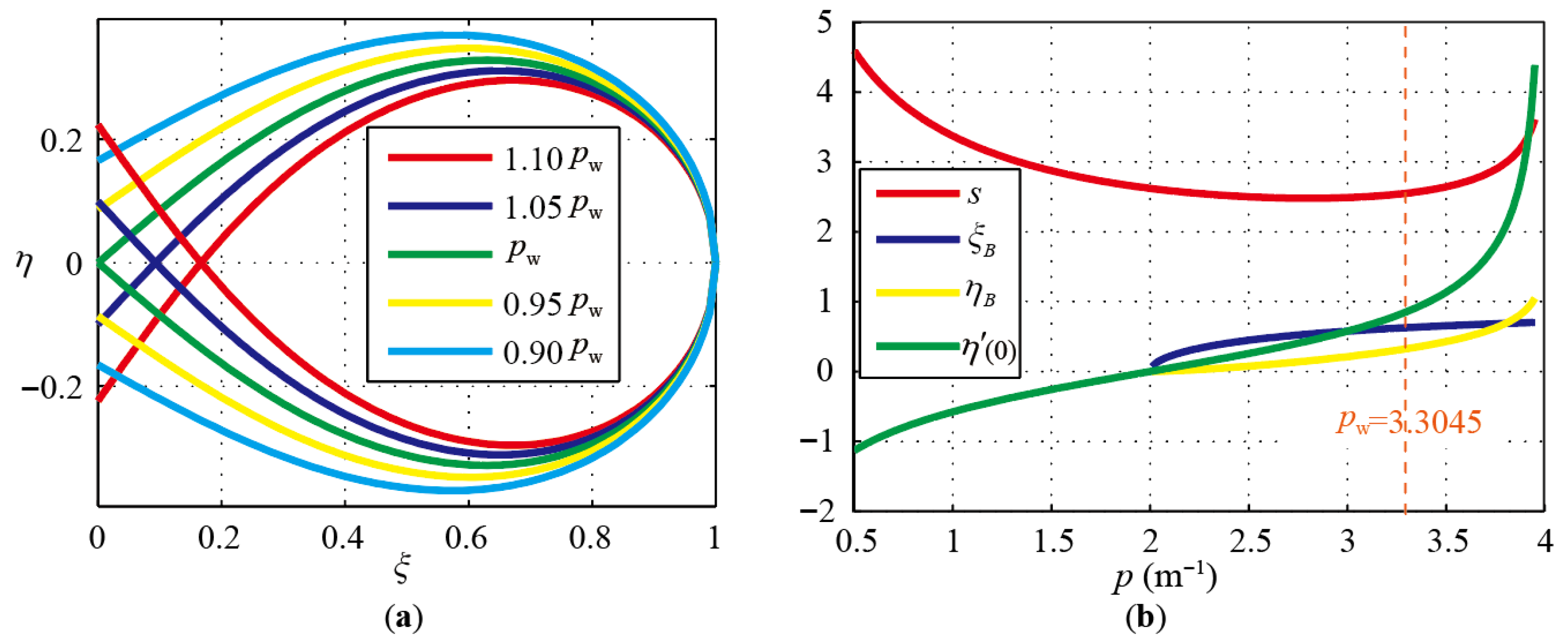
, different coiled shapes of a straight beam with simple joints at the ends are generated, as shown in
Figure 5a. Let
be the value of
for a standard water-drop. Curves of 0.9 to 1.1 times of
are drawn for comparison. The curves of
,
,
and
with
as variables are also drawn in
Figure 5b.
As can be seen in
Figure 5, “X”-shapes are produced with negative distances
, while “C”-shapes are generated with positive distances
. The over-buckling “X”-shapes could be employed in packages for larger compaction ratios. Meanwhile, the under-buckling “C”-shapes can be observed in the deployment process and in the in-plane equilibria in a later section.
There is at most one complete circle in the shapes depicted in
Figure 5, if only the ends are simply tied together, which results in
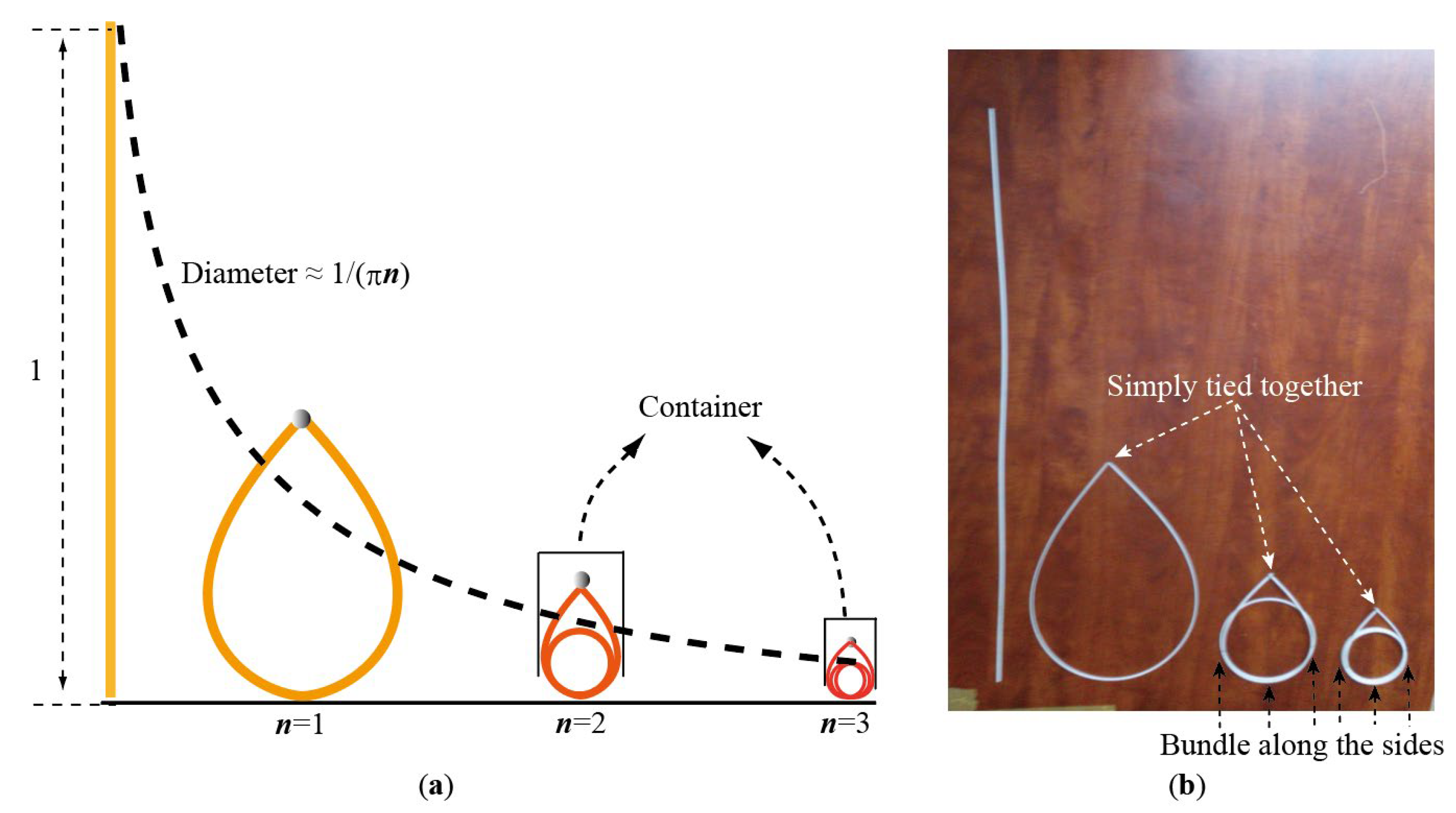
. It is unstable for a water drop with more than one circle, and additional constraints are needed to keep the shape, such as a container. As shown in
Figure 6a, when the circles
are 2 or 3, a container is needed.
Figure 6b illustrates the physical models, with wires bundled along the left, bottom and right sides of the coiled beams.
As defined before, if the in-plane compression ratio is the ratio between the length of the straight beam and the size of its maximum coiled shape, the compression ratio is about
if an edge is coiled into
circles, as shown in
Figure 6.
As defined before, if the in-plane compression ratio
is the ratio between the length of the straight beam and the size of its maximum coiled shape, the compression ratio is about
if an edge is coiled into
circles, as shown in
Figure 6. However, in practical engineering applications, stabilizing such multi-loop shapes almost inevitably requires a collection container, latching elements, and careful consideration of manufacturing tolerances. Therefore, a practical upper limit of
or
loops should be expected to avoid exceeding the material’s ultimate strain and to ensure the reliability of the latches. For large-scale structural requirements, rather than endlessly increasing the loop count of a single edge, utilizing multi-layer sub-pyramids (as will be discussed in
Section 4) is a more scalable approach.
3. Water-Drop Deployment Simulation
The analytical solution in the last section is only applicable to static problems. For the simulation of the water-drop buckling deployment, flexible multibody dynamics with beam elements, which is suitable for large deformation, large displacement, and large rotation, is necessary.
In this section, geometrically exact beam elements are introduced, along with multibody dynamics and the solution of the system equations. Then, the simulation results are compared with those in the deployment experiments of water-drop buckling.
3.1. Geometrically Exact Beam Elements
Geometrically exact beam elements (GEBEs) are adopted for the numerical simulation and analysis of the flexible pyramid deployment. The high accuracy and efficiency of the GEBEs have been verified by numerous studies in various engineering applications, especially for scenarios with large deformation, large displacement, and large rotation.
The Euler’s rotation vector
is utilized for global attitude description of a beam node, where
and
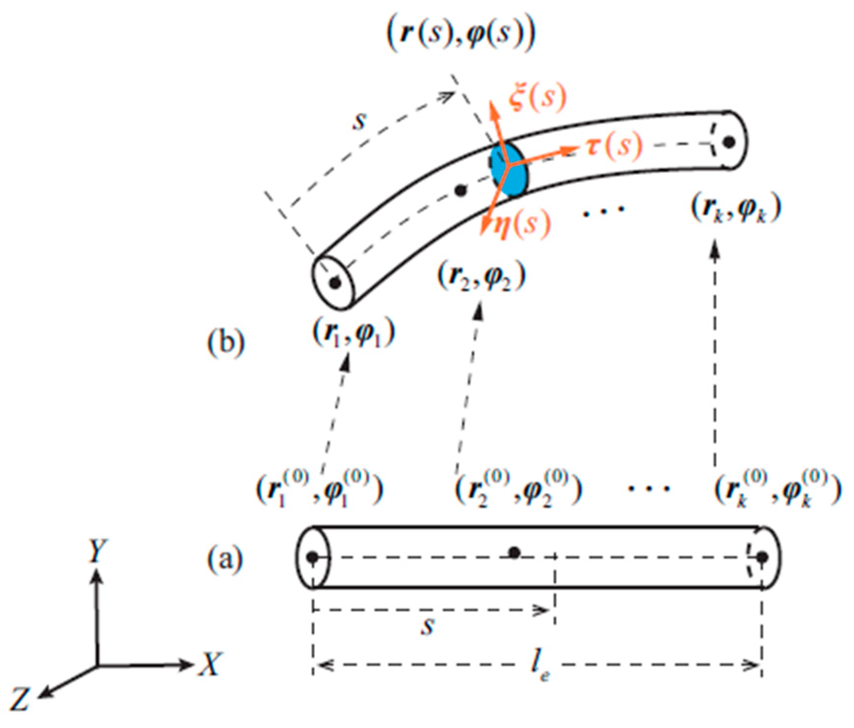
are the rotation angle and rotation axis of the node coordinates with respect to the global coordinates, respectively. As shown in
Figure 7, for an interior position
in the beam element with
nodes, the attitude parameters
at arc length
are interpolated in the same way as the displacement parameters
, and the attitude is given by the rotation matrix, i.e.,
wherein
are the shape functions of Lagrange interpolation,
are the displacement and attitude parameters of node
, and the rotation matrix is given by the Rodrigues’ rotation formula [
31] as
and
is a
identity matrix, and
is the skew-symmetric matrix of vector
.
Let the beam strains along and around the three axes be
wherein the normal strain
, engineering shear strains
,
and rotation strains
are given by
and
Although the overall deformation of the complete beam may be large, that inside an element is still small. Therefore, a linear constitutive relation with the matrix
is utilized to compute the elastic energy as
where
is the elastic modulus,
is the shear modulus,
is the section area,
are the inertia moments of the beam section due to the axes
, and
is the element length.
Then, the stiffness matrix of the element
with the vector of degrees of freedom (DOFs)
is given by
Substituting Equations (16)–(26) into Equation (27) yields a highly nonlinear expression.
For the simplification of the mass matrix, a concentrated mass
at the node
is adopted, and the gyroscopic force at the node is ignored. The concentrated mass matrix of the node
is therefore
The system stiffness matrix and system mass matrix of the beam elements can be directly assembled by and according to the positions of their DOFs within the system DOFs vector . No coordinate transformation is needed for the meta-matrices and because the global displacements and attitudes have been utilized in the computation. However, these meta-matrices themselves are highly nonlinear with respect to the parameters .
To “tie” the edge ends of a pyramid together, corresponding beam-end nodes are constrained with the following spherical joints as
wherein
is the index set of the main nodes,
is the index set of the slave nodes. When assembling the system stiffness and mass matrices, the meta-matrices of the slave nodes are eliminated into those of the corresponding main nodes, and the dependent DOFs
are removed from
. For the sake of notational simplicity, we still denote the independent DOFs as
in later sections.
Corresponding details of the deduction process and numerical computation method of the element stiffness matrix have been presented in the author’s earlier work [
32], and readers can refer to the original paper for more details.
3.2. Flexible Multibody Dynamics
The first-category Lagrange equations [
31] of the holonomic constraint problems are adopted to present the system equations of the flexible multibody system as
wherein
is the generalized coordinate vector,
is the Lagrange multiplier vector,
is the Lagrange function,
is the non-conservative extrinsic generalized force vector calculated by the principle of virtual work,
is the holonomic constraint function vector. In the discrete time steps, the generalized speed
and acceleration
are interpolated by backwards differential formulas (BDFs). Take
and
as functions of
. Then, for clarity, denote
, and Equation (30) can be written as
Equation (31) can be solved by the Newton Iteration using the following linearized equations.
Equation (32) will converge to
and
at the current time steps and then proceed to the next time steps. In the process of Newton iteration solving, the Jacobian matrix on the left-hand side of Equation (32) may be highly ill-conditioned when a small time step size
contributes
times to the mass matrix due to the BDF interpolation. To reduce the condition number, we utilize the following equivalent formulation for the actual Newton iteration.
For the simulation of retraction and deployment processes, a time integration method for stiff problems is required, such as the backward differential formulas (BDFs). Readers can refer to the authors’ earlier work [
33] for more deduction details.
To ensure that the simulated deployment dynamics—particularly the jamming and energy release scenarios—are physically accurate and not artifacts of the time integrator, a rigorous energy balance is monitored. Physical dissipation in the system is captured strictly through the -continuous contact friction model and contact damping parameters. Meanwhile, numerical dissipation introduced by the BDFs is minimized by enforcing an adaptive time-step rule, ensuring that time steps are sufficiently small during high-velocity unfolding phases.
3.3. Deployable Simulation and Experiment Verification of a Water-Drop
With the geometrically exact beam elements and flexible multibody dynamics described above, the buckling and deployment of the water-drop shape are simulated and compared with physical experiments.
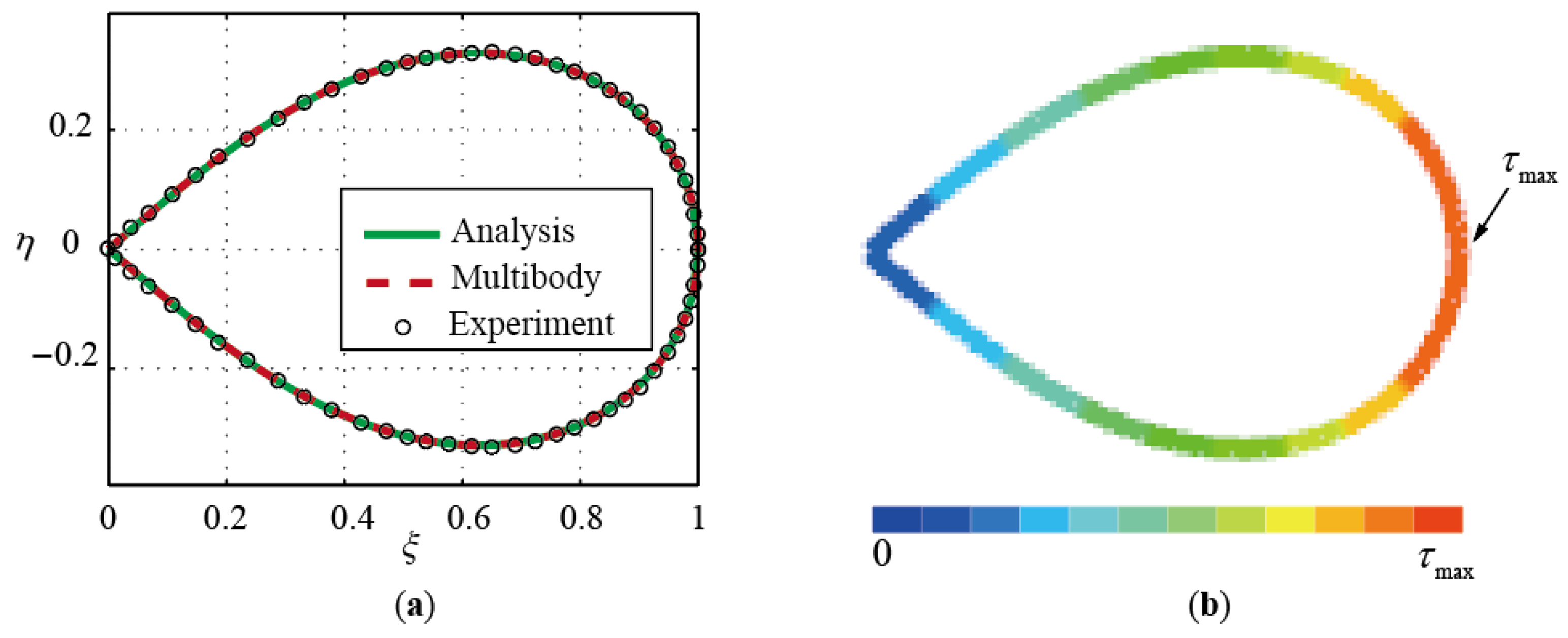
Figure 8 shows the water-drop buckling simulation results obtained using geometrically exact beam elements, along with the calculated stress distribution.
Figure 8a demonstrates a coincident shape among the results of analysis, multibody simulation and experiment. For a static equilibrium problem, the maximum stress occurs at the head of the water-drop shape.
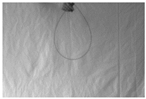
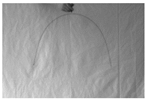
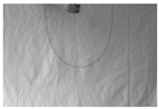
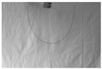
The deployment of a water-drop buckling shape is simulated and depicted in
Table 1. A straight beam is buckled into a water-drop shape, tied at the ends with wire, and hung up with a scissor under gravity. When the scissor cuts the wire, the constraints are released, and the water drop deploys freely under gravity. The falling and deploying process is photographed. The same numerical model is built and simulated, and the results at the same time moments are compared, as shown in
Table 1.
The straight beam is made of a carbon-fiber-reinforced plastic (CFRP) material, and corresponding property settings in the simulation are as follows: density of 1464 kg/m3, Young’s modulus of 1.53 × 10¹¹ Pa, Poisson’s ratio of 0.3, gravity acceleration of 9.8 m/s2, and beta damping coefficient of 0.0015. The experiment results are in good agreement with the simulation results.
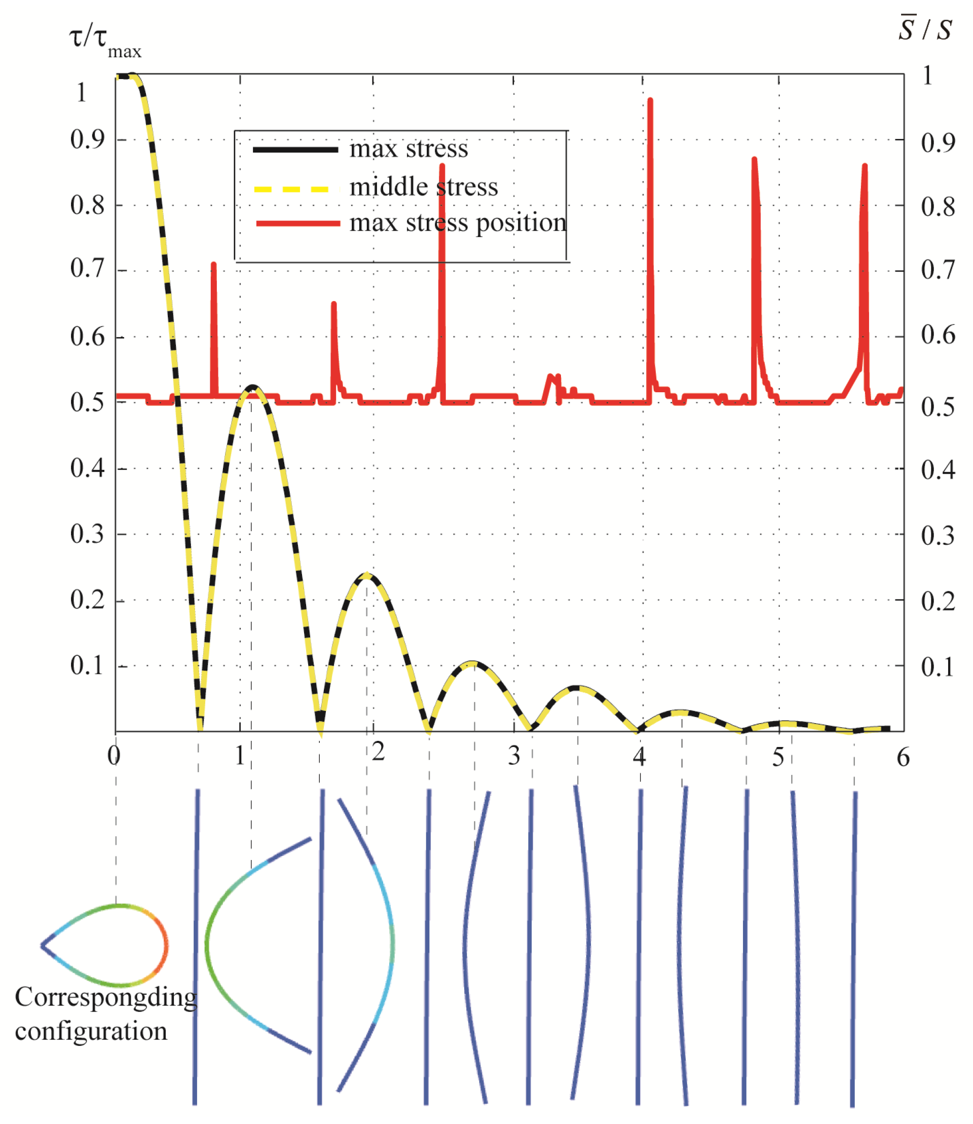
The maximum stress and its occurrence position are also calculated through the simulation. As shown in
Figure 9, the stress
is divided by the maximum stress
to obtain a stress ratio, and the occurrence position
is divided by the beam length
to present a position ratio. The comparison between the maximum stress and the middle stress reveals that, for the deployment of a single water-drop shape buckled from a straight beam, the maximum stress almost always occurs at the center of the beam length. Only when the stress is very small may the position of maximum stress occasionally shift to the beam ends.
4. Self-Deployable Pyramidal Truss Design
In this section, a design of a self-deployable pyramidal truss based on the water-drop buckling of straight beams is proposed. The basic idea is to coil each edge of the three-dimensional truss into buckled water drops for storage, and it can deploy with the elastic energy stored in the beams when the constraints are released.
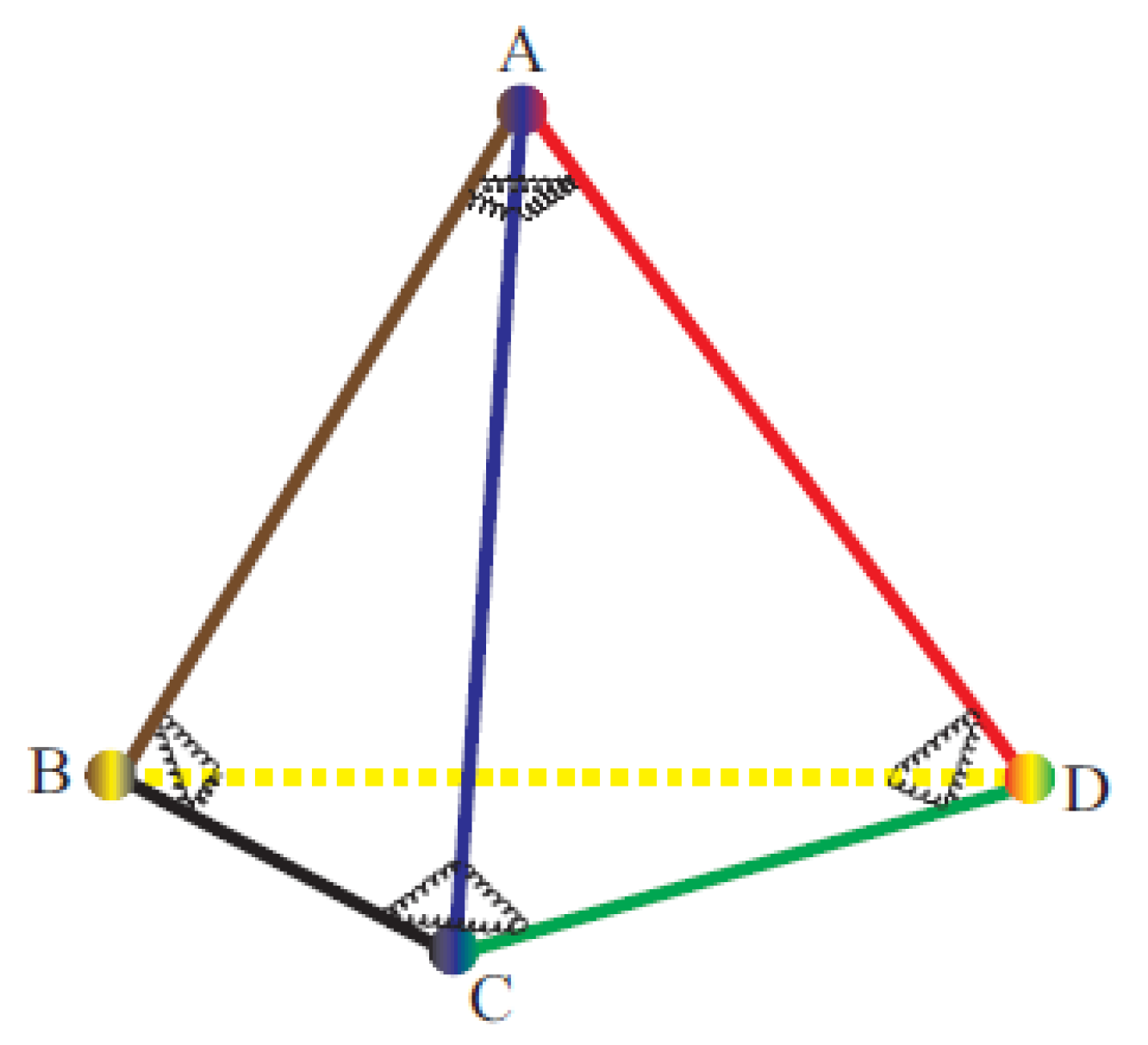
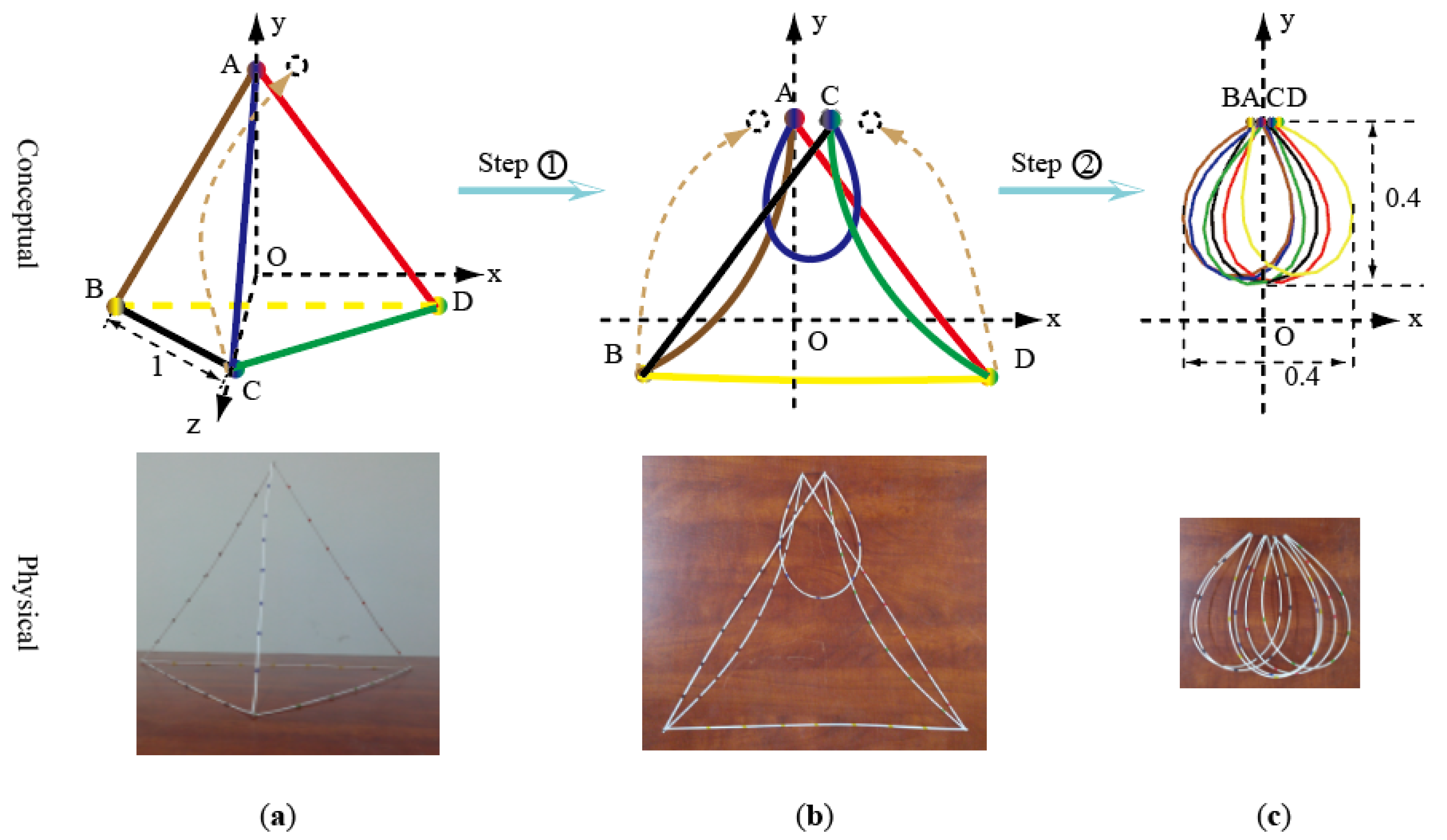
A coilable pyramid and its packaging process based on water-drop buckling are proposed in
Figure 10, including the conceptual figures and the physical implements.
Suppose the flexible edges are connected with ball hinges at the vertices. Two steps are required for the packaging process:
- ①
Press the out-of-plane vertex C towards vertex A to form an intermediate shape in the xy-plane with one water drop, as shown in
Figure 10b.
- ②
Pull the other vertices in the xy-plane towards vertex A and tie them together to obtain the final shape in
Figure 10c, which is composed of six water drops.
To deploy the compressed truss from
Figure 10c to
Figure 10a, the minimal level of control required is a simultaneous release of the tension wires. Releasing the vertices in sequential or asymmetrical patterns introduces unbalanced frictional forces, drastically increasing the probability of planar jamming. Simultaneous release allows the uniformly stored elastic energy to act synchronously, ensuring a reliable trajectory toward the 3D configuration.
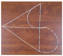
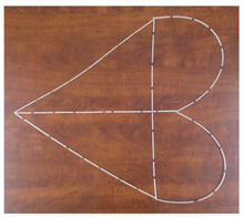
If all the edge lengths are 1.0, the size of the final packaged shape is less than
. The solid edges in
Figure 10 are made of polyvinyl chloride (PVC) rods, and they are simply tied together at the corners.
To deploy the compressed truss from
Figure 10c to
Figure 10a, we can release the vertices in the reverse sequence of coiling, or simply release the tension wires simultaneously. Other sequences should be avoided, as the deployment process may become stuck. The simulation of the coiling and deployment process of the pyramid truss requires self-contact modeling of the beam elements, which will be presented in the following
Section 5.
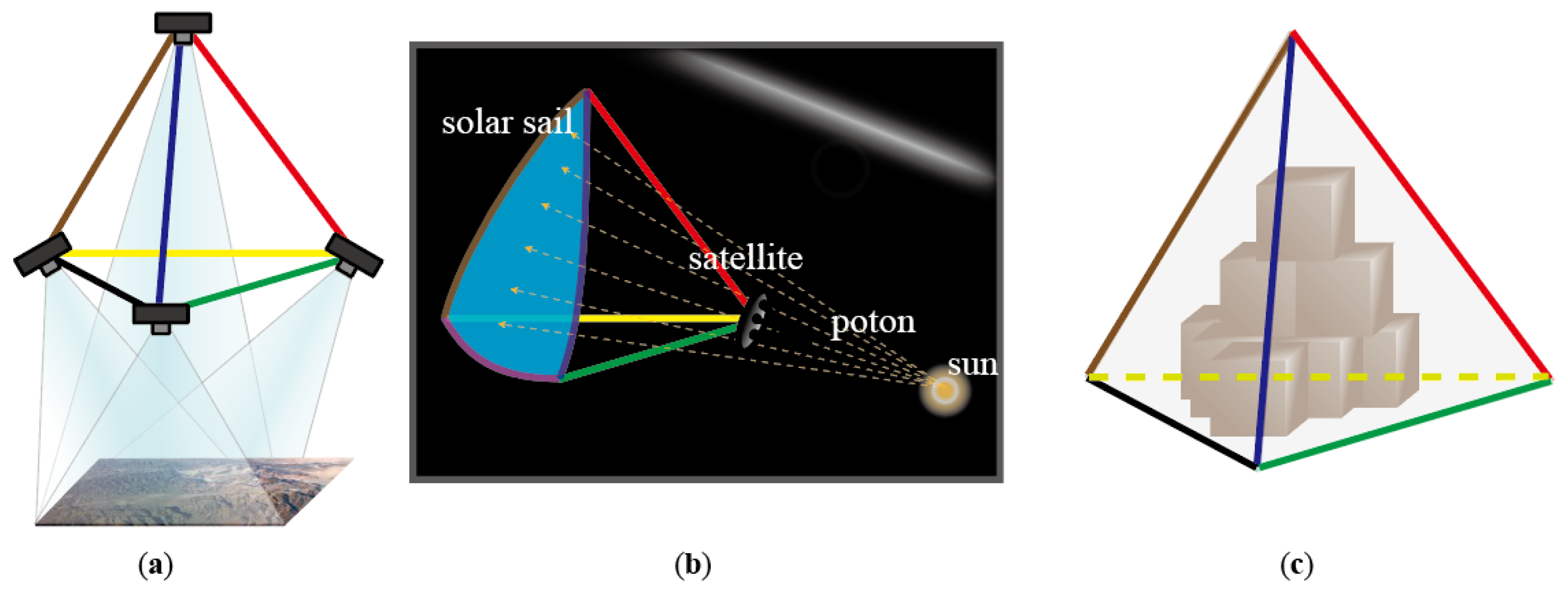
The flexible pyramid assembly is synchronously self-deployable and lightweight, because the deployment energies are stored along the entire length of the edges. These excellent features enable it to have potential applications in multi-satellite mapping [
34] masts, solar sails [
35,
36,
37], space station storage cabin, and any place that requires a three-dimensional basic supporting frame, as shown in
Figure 11.
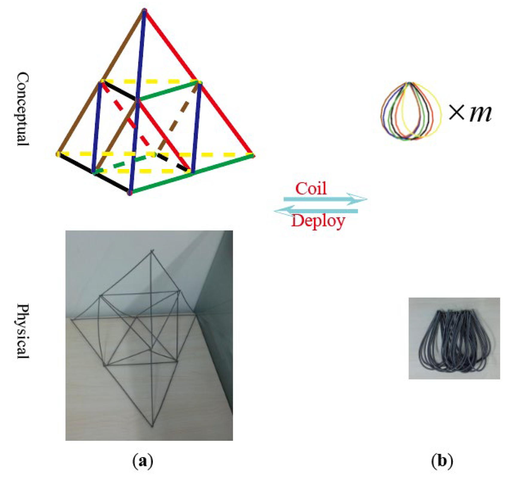
The self-deployable pyramidal trusses can also be regarded as basic cells to build more complex, larger, stiffer three-dimensional structures. As shown in
Figure 12, a larger pyramidal structural is made of several pyramidal trusses, which can be coiled. For larger assemblies composed of numerous pyramids, as shown in
Figure 12, the final packaged size is still
. The number of stack layers
in the z-direction is equal to the number of assembly edges. The edges of the physical model in
Figure 12 are soft helical springs, and the edges are simply tied together.
5. Deployable Simulation and Verification
In this section, a beam-on-beam contact formulation will be presented for the coiling and deployment simulation of the pyramidal truss. Three in-plane equilibrium configurations are analyzed, which introduce an out-of-plane reinforcement measure for the deployment process. Then, the simulation results of the coiling and self-deployment of the pyramidal truss are presented.
5.1. Beam-on-Beam Contact Formulation
Contact of the edges occurs in both the coiling and deployment processes. It is difficult to handle it with an analyze method. The contacts in the pyramid simulation include edge-to-edge contact and self-contact of edges. Through the edge discretization of GEBEs, both of these two kinds of contacts can be modeled by the beam-on-beam contact between two GEBEs.
Different from the beam-to-beam contact algorithms designed for the absolute nodal coordinate formulation (ANCF) [
38], either for frictionless cases [
39,
40] or small-sliding cases [
41], the presented contact algorithm is designed for GEBEs, frictional, and large-sliding cases.
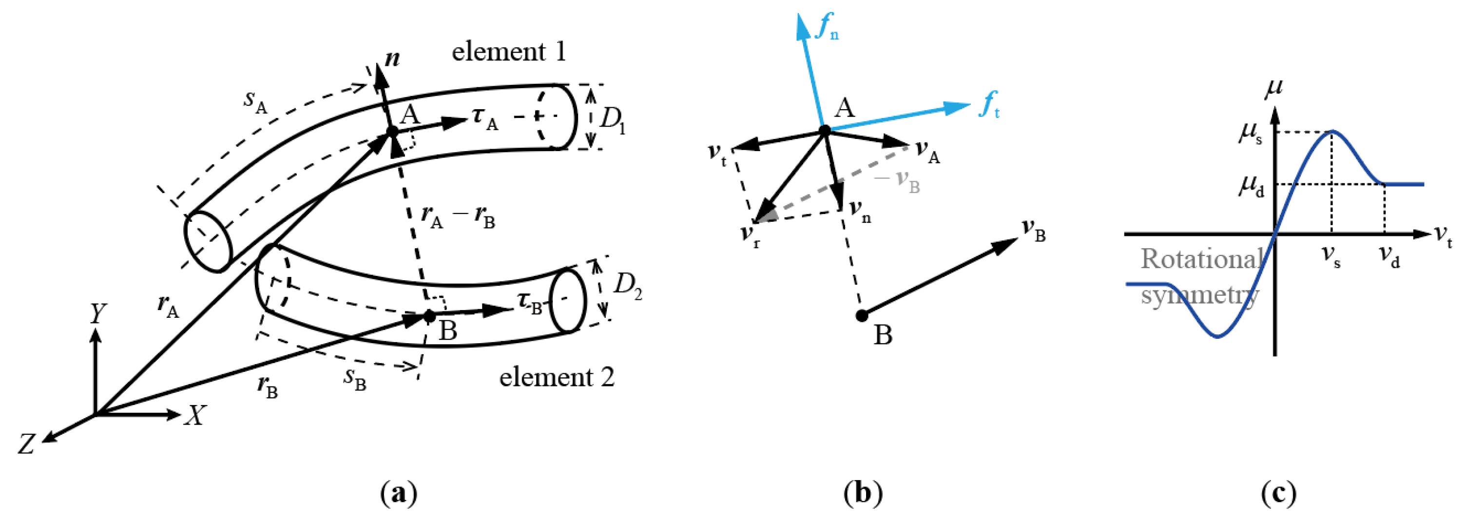
As shown in
Figure 13a, the contact positions A and B on the central axes of the two beam elements are determined by the minimal distance between the two parameterized central curves. Moreover, the following perpendicular relations should be satisfied.
wherein
,
,
and
are decided by the arc length parameters
and
according to Equations (16)–(18).
To determinate
and
, a nonlinear iteration is required. For example, the Newton iteration formula for
and
is given as
After the computation of
and
, the displacements
,
, and the velocity
,
, can be obtained using Equation (16). Then, given the diameters of the beams
and
, the embedded depth of the contact is
where a negative value of
implies a separation state.
As shown in
Figure 13b, the relative velocities in the normal and tangential directions are, respectively
wherein
is the unit vector of the contact normal direction, and
is the unit vector of the relative velocity direction. As shown in
Figure 13c, a
-continuous friction coefficient curve
[
33] is employed for the computation of the friction force, where
and
are the static and dynamic friction coefficients, and
and
are the static and dynamic friction velocities, respectively.
When
, the Hertz contact force [
42] at position A in the normal direction
and the Coulomb friction force [
43] at position A in the tangential direction
are, respectively
wherein
,
, and
are the contact stiffness, index, and damping, respectively. Moreover, the reaction forces at position B are in the opposite direction.
The contact-induced stiffness and damping matrices (including the friction effect) at position A are then, respectively
wherein
is the virtual displacement due to
, and because the system variables are independent after the DOFs elimination, we have
.
Let
be the set of all the contact positions and reaction positions, the contact stiffness and damping matrices of the system are calculated as
The set may only contain several pairs of contact and reaction positions for a given configuration, whether in an equilibrium computation or a deployment simulation. However, due to the geometrical nonlinearity in the deformations, contact may occur between any two non-adjacent beam elements.
For example, for a pyramid with 16 beam elements on each edge, as shown in
Figure 14, a total of 8940 contact pairs need to be defined before the simulation. Therefore, a fast contact pre-detection is necessary before the accurate calculation of contact positions, such as the sphere-to-sphere pre-detection method presented in the author’s earlier work [
33].
5.2. Three In-Plane Equilibria and the Out-of-Plane Reinforcement
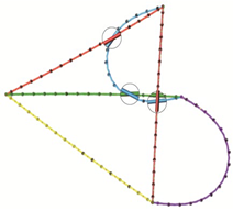
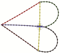
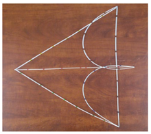
Three kinds of in-plane equilibria are discovered in the deployment simulation of a three-dimensional (3D) pyramid truss, as shown in
Table 2.
In the packaging process proposed in
Section 4, the three-dimensional (3D) pyramid is first pressed into an in-plane shape. The key problem is whether the packaged shape can self-deploy into the original 3D pyramid, or it just deploys into an in-plane shape and then reaches equilibrium. To answer this question, the in-plane equilibria of a flattened pyramid truss are discussed in this subsection.
The three in-plane equilibria in
Table 2 are obtained using the following formulation methods:
- ①
Release the vertices in the reversal sequence of coiling.
- ②
Release the vertices simultaneously.
- ③
Manually pressed it into the shape and then released.
In the simulation results, a space environment is assumed by setting the gravity to zero. Meanwhile, the experiment results are obtained on the ground, subjected to both the force of gravity and the desktop contact forces. Nevertheless, they result in the same in-plane equilibria shapes.
The essential reasons for the formulation of these in-plane equilibria are the twining of the edges and the lack of out-of-plane forces in the deployment process. The figures of simulation results in
Table 2 have enlarged the portions of edge-contact areas. The twining of the edges can be clearly observed. Because simple ball hinges are utilized for edge connections at the vertices, no out-of-plane forces can be provided for the 3D deployment. These equilibria also indicate that there is not enough resistance stiffness from the three-dimensional configuration to a flat equilibrium configuration.
A straightforward approach for out-of-plane reinforcement is to add supporting springs at the vertices. As shown in
Figure 15, short line-springs are attached between each pair of connected edges near the vertices.
It should be clarified that these springs act as passive elastic energy storage components, purely providing restorative stiffness, rather than active actuators. Thus, the concept remains a purely self-deployable framework. While resolving the planar trap issue constructively at the level of joint geometry is a viable physical alternative, passive springs provide a clear and easily modeled mathematical reinforcement. In addition, the design of joint geometry is a relatively complex undertaking—particularly when considering the case of multi-layered composite pyramids—we will address this subject specifically in a subsequent paper, in which we will detail the specialized design of such joint geometries through the application of systematic optimization methods.
Since the flat shape in
Figure 10b is formed by edge buckling, the reinforcement is then measured by the increase in buckling load of the straight edge. If the springs are close enough to the edge ends and are stiff enough, the supporting boundary of the edge changes from simple support to fixed support.
Without the supporting springs, according to the Mechanics of Materials [
44] and theory of elastic stability [
45], the minimum critical buckling load of a simply supported beam is
wherein
is the Young’s modulus,
is the diameter of the edge beam, and
is the length of the edge beam.
For the case with the supporting springs, the spherical joints at the vertices can be approximately regarded as fixed joints. This increases the minimum critical buckling load by four times to
Equation (46) also indicates that the minimum critical buckling load decreases as the length of the pyramid edge increases, and vice versa. A large-scale 3D pyramid truss may encounter this issue, and the solution is to use sub-pyramids to construct a multi-layer pyramidal truss by limiting
to a small value, as shown in
Figure 12.
It must be noted that the current physical prototype captured in our photographs acts as a fundamental proof-of-concept for the basic water-drop buckling behavior and visually demonstrates the planar equilibria. The physical integration of these micro-springs into the vertex joints is slated for future manufacturing. In our GEBE numerical simulations, to demonstrate this reinforcement theoretically, the design parameters for the springs were set with a stiffness of N/m and an installation offset of m from the terminal ends.
5.3. Simulation Results of the Pyramidal Truss Packaging and Deployment
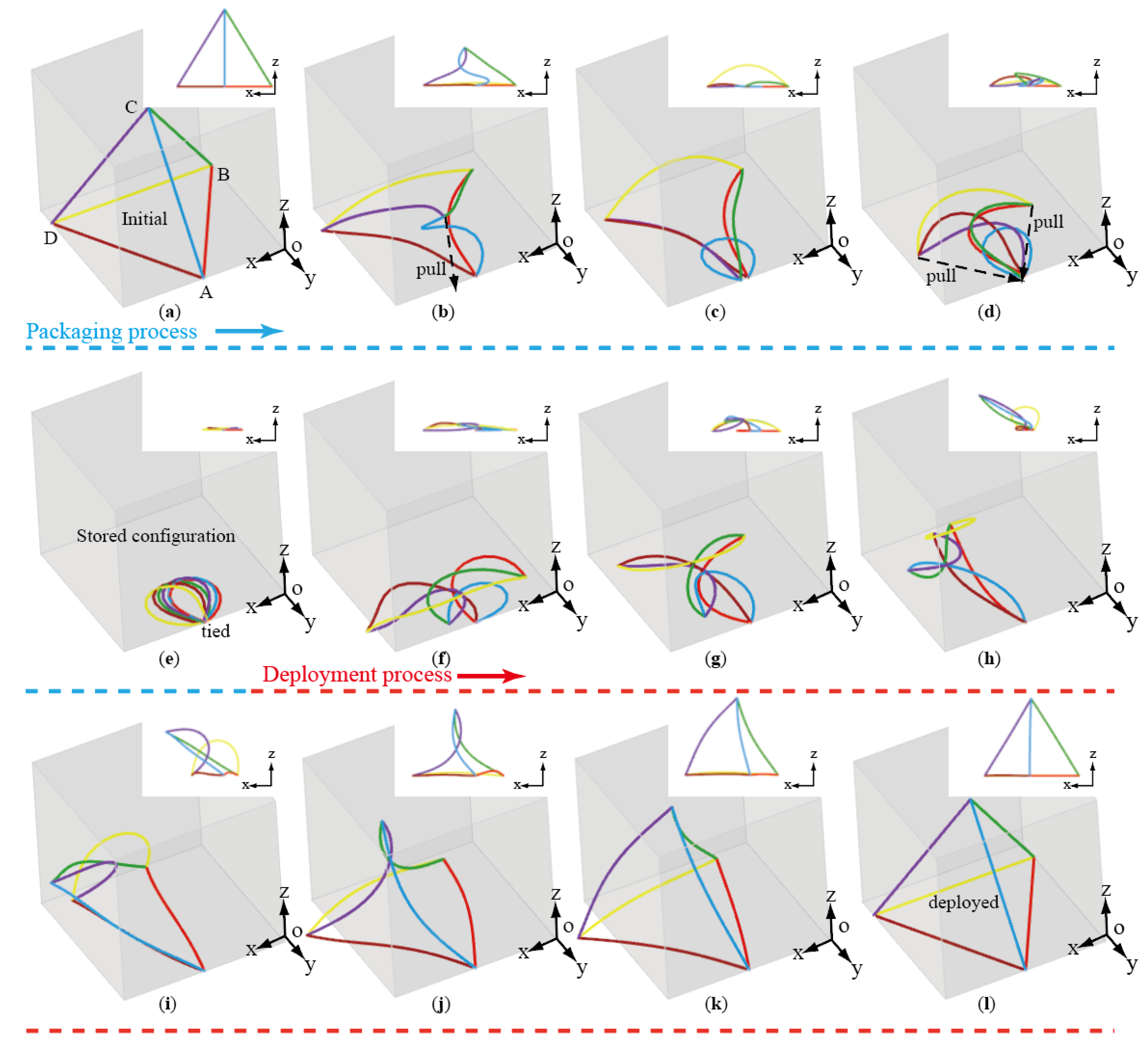
With the reinforcement springs, the packaging and deployment processes are simulated using flexible multibody dynamics, taking into account all edge contacts and self-contacts. The numerical results are shown in
Figure 16, with the y-direction view in the right corner of each figure.
The package process, as described in
Section 4, is shown in
Figure 16a–e. First, point C is pulled to point A, and then points B and D are also pulled to point A.
The deployment process is shown in
Figure 16e–l. The constraints are released simultaneously at the moment of
Figure 16e. It shows that the packaged pyramid deploys in the plane first and then quickly expands into a three-dimensional structure with the help of the supporting springs at the vertices.
The effect of the vertex reinforcement springs is also clear in
Figure 16c,d,f–i. In these pictures, the beams are separated at the corner by the spring forces, and the twining of the edges is avoided. In
Figure 16l, the pyramid truss is coiled and deployed by itself successfully in the simulation.
6. Conclusions
This paper proposes a self-deployable pyramidal truss based on water-drop buckling. The basic characteristics of the water-drop buckling of a straight beam are analyzed in detail. A compression ratio of 2.5 is obtained with a single water-drop, and larger ratios are obtained with generalized water-drops with more circles in the buckling. With water drops as the basic shape, a lightweight self-deployable pyramid truss has been designed, which shows potential in space applications.
Considering the possibility of getting stuck in planar equilibrium configurations, corner reinforcement measures are applied to ensure the successful deployment of the packaged pyramid. Flexible multibody dynamics with geometrically exact beam elements and the contacts between them are introduced to simulate these deformations and dynamic processes. Several physical experiments and numerical simulations are carried out for a coincidence comparison, which ensures the successful design of the self-deployable pyramid truss.
Through multi-circle bending of the beam edges and multi-cell design of the pyramids, a higher folding ratio of 2.5 is achieved for a single cell. While 2D mechanisms like tape-springs or Miura-ori membranes can achieve extreme planar compaction, the 2.5 compression ratio presented here represents a highly efficient 1D-to-3D volumetric transformation for frame-based trusses, maintaining superior continuous structural stiffness compared to discrete membrane folds.
Subsequent research will primarily advance along two distinct but complementary directions: mechanical joint optimization and material durability under long-term stowage. From a structural perspective, future work will focus on the detailed design of engineering connectors and specialized micro-hinges for reinforcement springs. This will ensure orderly deployment without unwanted edge contact, while allowing optimization methods to be applied to the connector designs of multi-layer pyramids or other complex configurations. From a materials perspective, practical space applications demand rigorous evaluation of CFRP reliability. Given that the water-drop configuration induces extreme curvature at the apex, prolonged packaging poses severe risks of stress relaxation, polymer matrix creep, and micro-cracking. Because such material degradation could permanently diminish the essential spring-back force below the threshold required for successful deployment, extended fatigue and stowage testing of these composite rods will be a critical focus of our ongoing investigations.