Article

Study on the Influence of Penetration Parameters of Triangular Mandrel Shoes on the Smear Zone in Soft Soil

1
School of River and Ocean Engineering, Chongqing Jiaotong University, Chongqing 400074, China
2
College of Civil Engineering, Zhejiang University of Technology, Hangzhou 310014, China
*
Author to whom correspondence should be addressed.
Appl. Sci. 2026, 16(8), 3645; https://doi.org/10.3390/app16083645
Submission received: 13 February 2026 / Revised: 3 April 2026 / Accepted: 7 April 2026 / Published: 8 April 2026

Abstract

During the installation of prefabricated vertical drains (PVDs) in soft soil foundations, the smear effect induced by mandrel shoe penetration can severely damage the soil structure and reduce permeability, thereby becoming a key factor restricting foundation consolidation efficiency. Previous studies have generally neglected the smear disturbance caused by the geometry of the mandrel shoe. Although existing studies have conducted numerical and theoretical analyses on the smear effect induced by PVD installation, most of them are still based on equivalent circular simplifications and are therefore unable to characterize the anisotropic disturbance induced by a triangular mandrel shoe. To address this limitation, a three-dimensional CEL penetration model considering the real triangular geometry was established, and the traditional cavity expansion theory was directionally modified. The effects of penetration rate, geometric angular structure, and soil type of the triangular mandrel shoe on the smear zone were systematically investigated. The results show that, with increasing penetration rate, the near-field peak stress and far-field displacement increase simultaneously; from slow penetration to fast penetration, the near-field peak stress increases by approximately 42%. By quantitatively defining the critical threshold corresponding to a sharp 50% attenuation in radial displacement as the boundary of the strong smear zone, it was found that increasing the size of the mandrel shoe significantly amplifies the geometric corner effect, and the near-field disturbance range increases by about 21% compared with that of the small-sized case. The larger the size, the more pronounced the anisotropic disturbance characteristics become: the stress concentration effect and displacement splitting in the vertex direction are further enhanced, causing the disturbance range in that direction to far exceed that in the side direction. Soil properties are the key medium parameters controlling the smear zone. Owing to its relatively high stiffness index and skeleton strength, Clayey Silt shows the largest displacement range, whereas Common Clay exhibits the smallest smear zone because of its stronger structural constraint. The modified theoretical model agrees well with the CEL numerical simulation results, verifying its effectiveness under conditions that consider the geometric characteristics of the mandrel shoe. This study provides a theoretical basis and numerical support for the structural design of mandrel shoes in soft-ground PVD construction.

1. Introduction

With the rapid economic development of coastal regions, the demand for land reclamation and infrastructure construction on deep soft soil foundations has continued to increase. The prefabricated vertical drain (PVD) combined with vacuum preloading has become one of the mainstream techniques for soft ground improvement because of its short construction period, low cost, and significant consolidation efficiency [1]. During PVD installation, the drain is forcibly driven into the soil by means of a mandrel shoe. This process imposes strong squeezing and shearing on the surrounding soil, destroys its natural structure, significantly reduces the permeability of the remolded zone, and consequently induces a smear effect [2,3]. The smear effect increases the resistance to pore water pressure dissipation, thereby reducing foundation consolidation efficiency [2,4].
To better understand and control the smear effect during PVD installation, existing studies have mainly been conducted from three perspectives: theoretical analysis, numerical simulation, and experimental observation [2,3,4,5]. In terms of theoretical research, cavity expansion theory has been widely used to analyze the extent of the smear zone; however, most existing models are established on the basis of the equivalent circular boundary assumption and therefore cannot directly characterize non-circular mandrel shoes, particularly the anisotropic disturbance induced by a triangular mandrel shoe [6,7,8]. Existing theoretical studies on PVD improvement and equivalent models have mostly treated the geometry using an equivalent circle or equivalent boundary, making it difficult to reveal the differential effects of the mandrel shoe corners and sides on the expansion of the smear zone [6,7,8]. In fact, the traditional cavity expansion theory has obvious limitations when applied to triangular and other irregular mandrel shoes commonly used in engineering practice [6,9]. Similarly, the simplification based on equivalent diameter neglects the damage effect of corners and is unable to reflect the non-uniform shear bands, anisotropic stress concentration, and the characteristic splitting–squeezing mechanism induced by a triangular mandrel shoe, which may lead to an overestimation of the disturbance magnitude in the vertex direction [6,9,10]. Therefore, a more refined theoretical analysis considering the geometric characteristics of triangular mandrel shoes is still necessary, and existing studies remain insufficient to fully reveal their complex contact behavior and large-deformation mechanism [5,10].
In terms of numerical simulation, in recent years, large-deformation numerical methods such as ALE and CEL have been applied to analyze the penetration of mandrel shoes into soft soil, and they have successfully revealed the large-deformation response of soil and the propagation pattern of disturbance [11,12]. However, most existing studies are still based on equivalent circular or axisymmetric boundary simplifications, and thus cannot accurately characterize the local stress concentration and directional splitting effect at the corners of a triangular mandrel shoe [9,12]. For large-deformation penetration problems in geotechnical engineering, numerical approaches have further developed into advanced frameworks involving ALE, DEM coupling, and formulations considering strain softening, rate effects, and multiphase coupling. Different methods have their own applicable ranges: ALE has advantages in handling boundary evolution during penetration; DEM and its coupled methods are helpful for revealing particle-scale mechanisms, but they are currently mainly used for sand or idealized particulate systems and still face high computational cost and parameter calibration difficulties in three-dimensional deep penetration analyses in clay; meanwhile, advanced finite element methods considering strain softening and rate effects are beneficial for improving the description of soft clay remolding behavior. Overall, existing advanced numerical methods each have their own strengths, and no universally optimal framework is available for all problems. For the triangular mandrel shoe penetration problem considered in this study, which simultaneously involves real non-axisymmetric geometry, corner contact, strong soil backflow, and multi-parameter three-dimensional comparative analysis, the CEL method is more suitable for the objectives of this study in terms of avoiding severe mesh distortion, preserving geometric fidelity, and enabling systematic parametric investigation [10,11,12].
In terms of experimental observation, transparent soil tests combined with PIV technology have provided an important means for identifying the extent of soil disturbance and the evolution of the displacement field, and have also demonstrated that the shape of the mandrel shoe can significantly affect the degree of soil remolding [3,10]. However, existing studies have mostly focused on the overall disturbance range or the equivalent smear thickness, and quantitative discussion of the difference in disturbance between the vertex direction and the side direction under a triangular cross-section remains insufficient [4,10].
Based on the above research background, this study takes the triangular mandrel shoe commonly used in engineering practice as the research object, establishes a three-dimensional CEL penetration model considering the real geometric characteristics, and validates the model response using transparent soil/PIV test results. On this basis, shape correction factors for the vertex direction and the side direction are introduced to modify the traditional cavity expansion theory, thereby establishing a prediction framework for the extent of the smear zone applicable to triangular mandrel shoes. Compared with existing studies that are mostly based on equivalent circular or axisymmetric simplifications, the main contributions of this study are as follows: revealing the directional disturbance mechanism induced by the corner effect of the triangular mandrel shoe; achieving a quantitative characterization of the difference in smear zone expansion between the vertex direction and the side direction; and improving the reliability of the results through cross-validation among numerical simulation, experiments, and theory. The findings can provide a theoretical basis for mandrel shoe structural optimization and construction parameter design in soft ground treatment.

2. Overview of the Transparent Soil Experiment

2.1. Experimental Setup

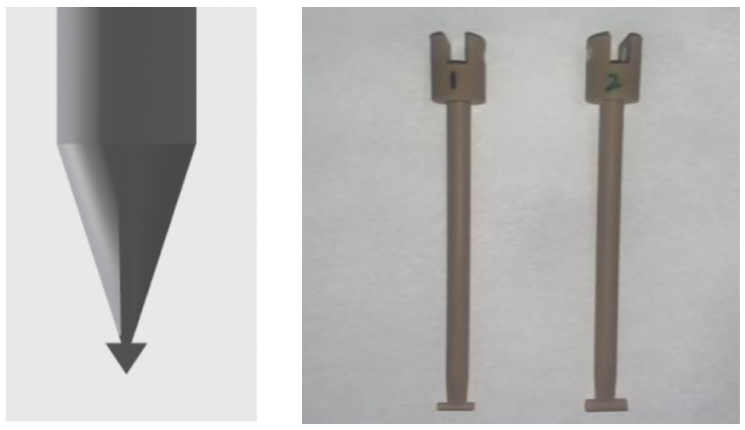
As shown in Figure 1, the mandrel shoe adopts a triangular structure and mainly consists of a sleeve and a triangular tip. The outer diameter of the sleeve of the prefabricated vertical drain mandrel shoe is 130 mm, the length of the triangular sleeve is 500 mm, and the length of the triangular body is 70 mm. The experiment mainly focuses on the influence of triangular geometric characteristics on the extent of the smear zone, and three sizes were selected for investigation: a base length of 40 mm with a height of 30 mm, a base length of 50 mm with a height of 40 mm, and a base length of 60 mm with a height of 50 mm. The soil model was designed as a regular cylinder, and both its radius and height were set as multiples of the outer diameter of the sleeve to satisfy the assumption of an undisturbed far field. This geometric design facilitates the investigation of the smear effect induced by the mandrel shoe structure during installation. Through this experimental setup, the formation of the smear effect during mandrel shoe installation can be simulated, thereby providing data support for engineering applications and theoretical research.
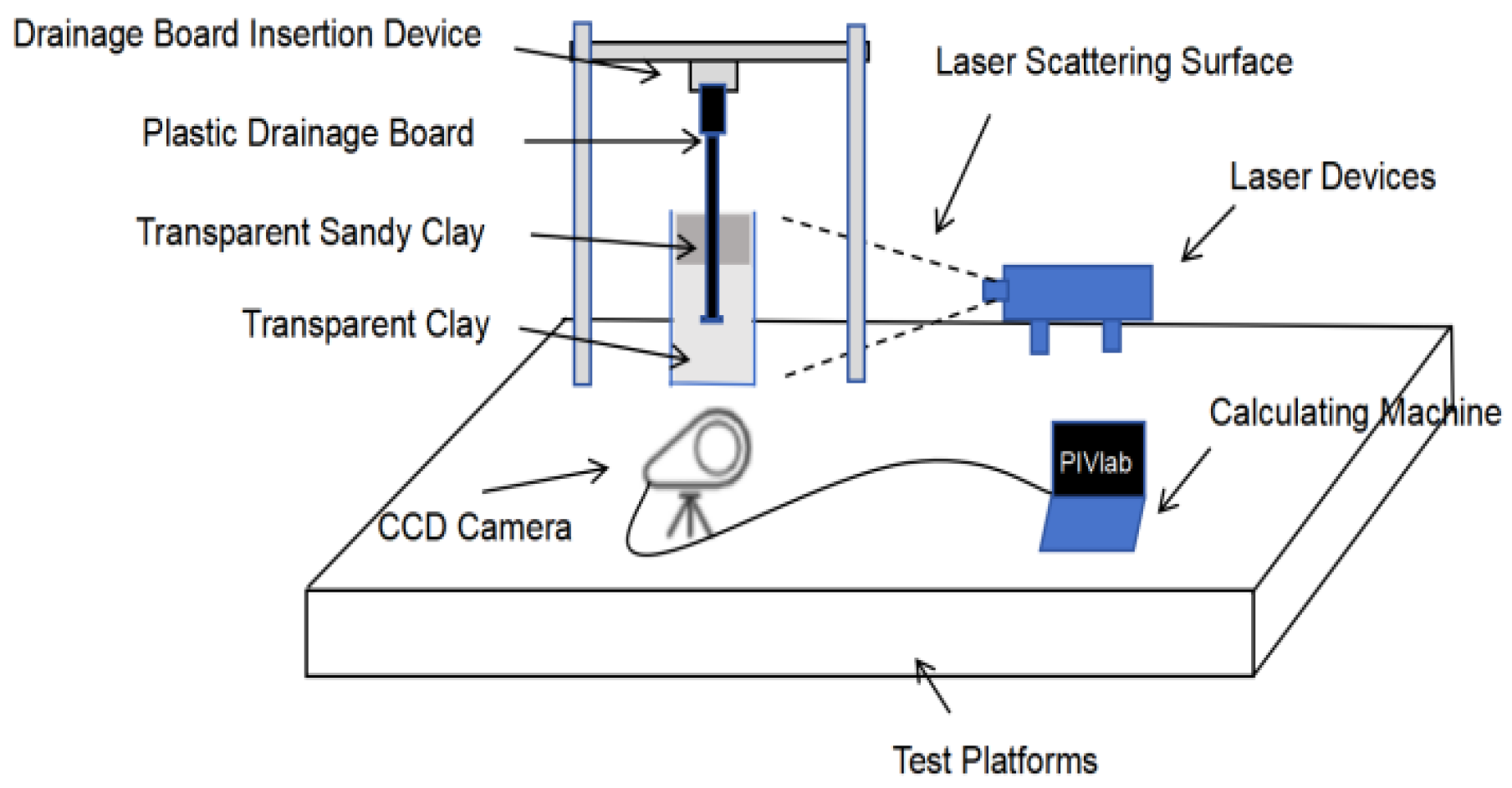
This experiment was designed to investigate the smear effect generated during the installation of the mandrel shoe for prefabricated vertical drains. As shown in Figure 2, the system consisted of a model box, a drain installation device, a high-speed CCD camera, a laser source, a computer, and a prefabricated vertical drain model equipped with a triangular mandrel shoe. The laser source was positioned on the left side of the model box, and the emitted laser sheet passed through the central region of the box, forming a central observation plane along the installation axis of the mandrel shoe. Image acquisition was carried out using a Mikrotron MotionBLITZ EoSens (Mikrotron GmbH, located in the suburbs of Munich, Germany) camera with a resolution of 1696 × 1710, and the image capture interval was set to 250 ms under a constant penetration rate of 1 mm/s. The displacement field was determined using the fast Fourier transform (FFT) cross-correlation algorithm in PIVlab (R2024b) by tracking the unique speckle pattern formed by quartz sand particles and PSP tracer particles [13]. The dimensions of the model box were 130 mm × 130 mm × 250 mm, with an open top, a wall thickness of 6 mm, and a bottom plate thickness of 6 mm. The drain installation device consisted of an insertion unit and a fixing unit to ensure the stability of the mandrel shoe during installation. In the experiment, the installation rate of the mandrel shoe was maintained at 1 mm/s by adjusting the voltage, so as to simulate the insertion rate in practical construction. The high-speed CCD camera was installed 1.2 m in front of the model box to capture the dynamic process in real time. The laser source was an integrated laser sheet generator, producing a sheet of light to illuminate the transparent soil sample and form a dynamic speckle field. The computer control system was used for image acquisition and processing, and PIVlab and Tecplot were employed for subsequent data analysis. By capturing the variation in the speckle field with the high-speed CCD camera, the system enabled visualization of the mandrel shoe installation process. The main purpose of the transparent soil/PIV test in this study was to obtain the visualized response of soil displacement field evolution and disturbance extent during mandrel shoe penetration, so as to validate the capability of the numerical model in capturing displacement attenuation patterns and disturbance morphology, rather than to establish a strictly scaled model in the sense of geometric, stress, and time similarity under prototype conditions [14].
To ensure the repeatability and reproducibility of the experimental results, the image acquisition and data processing procedures were standardized in this study. During image acquisition, the CCD camera and laser sheet source were fixed and aligned before each test, with the relative position between the camera and the model box, lens focal length, aperture, exposure time, frame rate, and resolution kept constant. A calibration plate was used to complete the pixel-to-physical-length conversion and distortion correction. The thickness and incident position of the laser sheet were also fixed to ensure consistency between the illuminated section and the observation plane. During the tests, a unified installation rate control procedure was adopted, and key conditions such as ambient temperature and sample resting time were recorded to reduce the influence of the rheological behavior of the transparent soil material on the results.
In the data processing stage, PIVlab was used for displacement/velocity field inversion with the same image preprocessing strategy and the same correlation calculation parameters, and a parameter sensitivity check was conducted for representative cases to confirm the stability of the results [15]. Tecplot was used only for visualization and post-processing of the finalized datasets, thereby avoiding statistical bias introduced by differences in plotting settings.

2.2. Experimental Materials

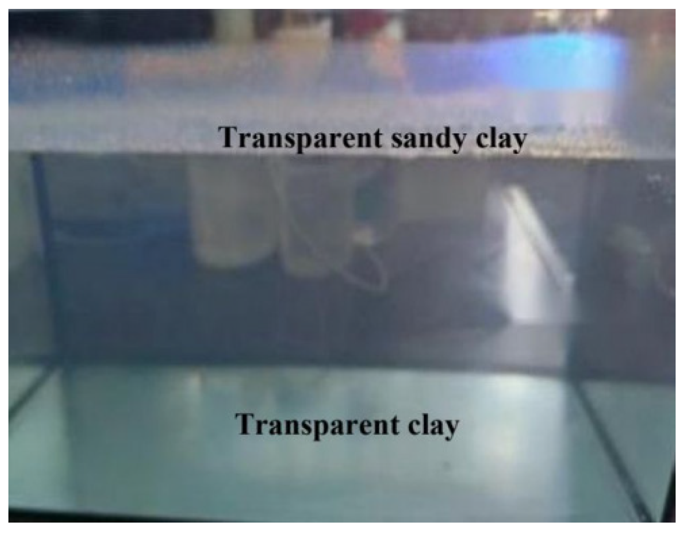
Soft ground treatment projects are mainly carried out in coastal and port areas, where the soil is commonly mucky soil with high organic content, large porosity, and low structural strength, and is therefore prone to softening. To simulate this soft soil environment, a layered soil model with sand over clay was adopted in this study, and composite transparent soil samples were prepared using a layer-by-layer method, as shown in Figure 3. The physical properties of the transparent soil are similar to those of natural soil, enabling effective simulation of both clay and sand characteristics and thereby allowing visualization of the mandrel shoe installation process [16,17].
In the experiment, transparent sand was prepared using quartz sand particles with a particle size of 0.5–1 mm as the skeleton material [18]. Transparent clay was prepared by mixing Laponite RD powder into a gel with a concentration of 3.5%, together with PSP tracer particles, to form the transparent soil [19]. To prepare the pore fluid for the transparent sand, No. 3 white oil and No. 15 white oil were mixed at a volume ratio of 1:9. For the preparation of transparent clay, deionized water was first added into the model box, followed by the addition of Laponite RD powder to form a gel through stirring, after which the mixture was allowed to stand for 24 h. Subsequently, the transparent sand layer containing white oil and the sand particles was poured alternately to complete the preparation of the upper sand layer. The entire process was conducted at a constant temperature of 25 °C.
The physical and mechanical parameters of the soils were selected based on the properties of common foundation soils and regional field data. To investigate the influence of different soil types on the smear effect, four typical soft clay types were considered in this study, namely Common Clay, Silty Clay, Clayey Silt, and Silt-in-pulverized. The corresponding physical and mechanical parameters are listed in Table 1, Table 2 and Table 3. Through analysis of the structural characteristics, strength, and permeability of different soils, it was found that Common Clay shows relatively low sensitivity to the smear effect, whereas Silty Clay and Clayey Silt exhibit a stronger smear effect. These soil characteristics provide an important theoretical basis for the analysis of the smear effect.
The parameter sets adopted in this study were not selected arbitrarily. They were determined based on three considerations: the commonly reported ranges of soil parameters in studies related to soft ground improvement and PVD penetration; the empirical ranges of physical and mechanical indices for soft clays commonly encountered in regional engineering practice; and the need to ensure representative comparisons among different soil types by emphasizing the relative differences in key mechanical parameters, such as elastic modulus, cohesion, and internal friction angle, rather than carrying out a strict back-analysis for a specific engineering site. Therefore, the parameter sets used in this study were mainly intended to reveal the relative response patterns of soil disturbance induced by mandrel shoe penetration under different soil conditions.

2.3. Experimental Program

To systematically investigate the effects of mandrel shoe geometry and construction parameters on the stress field and displacement field, three groups of control variables were designed in this study to comprehensively analyze the extent of the smear zone during mandrel shoe installation in soft clay.
(1) Penetration rate cases: Three penetration rates representing field construction conditions were considered, corresponding to low-, medium-, and high-speed installation. The specific cases are listed in Table 4.
(2) Mandrel shoe geometric size cases: Three sizes were selected to investigate their influence on the smear effect, namely, a base length of 40 mm with a height of 30 mm, a base length of 50 mm with a height of 40 mm, and a base length of 60 mm with a height of 50 mm. The specific cases are listed in Table 5.
(3) Four typical soft clay types were selected to analyze the influence of different soil properties on the extent of the smear zone, namely, Common Clay, Silt-in-pulverized, Clayey Silt, and Silty Clay. The specific cases are listed in Table 6.
The above cases can simulate common construction scenarios during prefabricated vertical drain installation and provide a parameter basis for the subsequent development of the prediction model for the smear zone.

3. Numerical Simulation Analysis

3.1. General Description of the Model

To investigate the formation mechanism and extent of the smear effect during the installation of a triangular mandrel shoe in soft clay, a three-dimensional large-deformation numerical model was established on the ABAQUS platform using the Coupled Eulerian–Lagrangian (CEL) method [20]. This model was used to simulate the penetration process of the triangular mandrel shoe in soft clay and to analyze the formation mechanism of the smear effect. By combining the advantages of the Lagrangian and Eulerian formulations, the CEL method can accurately describe the large-deformation contact between the mandrel shoe and the soil, while avoiding the mesh distortion problem commonly encountered in traditional Lagrangian analysis under large-strain conditions [12]. A Cartesian coordinate system was adopted in the model. The soil was discretized using an Eulerian mesh, whereas the mandrel shoe was modeled as a Lagrangian body. The penetration of the mandrel shoe was simulated by applying a vertical displacement. In addition, the contact definition in the numerical simulation considered both friction and separation effects, thereby ensuring a realistic representation of the pile–soil interaction.

3.2. Soil Constitutive Model

In this study, the classical Mohr–Coulomb model was adopted to simulate the mechanical response of different types of soft soil during mandrel shoe penetration. This model defines the soil yield condition based on the shear strength criterion and can effectively reflect the strength characteristics of soft clay under low to medium stress levels. It is therefore suitable for analyzing the local shear failure and displacement diffusion induced by mandrel shoe installation. To describe the nonlinear mechanical behavior of soft soil, the soil constitutive model was represented by the Mohr–Coulomb elastoplastic model, while the mandrel shoe and sleeve were simplified as rigid bodies because their stiffness is much higher than that of the surrounding soil.
The Mohr–Coulomb model was adopted because its parameters are clearly defined and it has good engineering applicability, allowing a reasonable description of the strength-controlled response of soft clay under low to medium stress levels and making it suitable for comparative analyses of different soil types [21]. The corresponding values of elastic modulus, cohesion, internal friction angle, and Poisson’s ratio were all taken from Table 3. These parameters were selected to represent the relative mechanical differences among different soil types, so as to analyze the evolution of displacement diffusion, stress concentration, and the extent of the smear zone during mandrel shoe penetration. It should also be noted that the soil in the present numerical analysis was modeled using the Mohr–Coulomb elastoplastic constitutive model, which is essentially rate-independent and can describe soil yielding, plastic deformation, and the stress–displacement response controlled by soil strength during penetration.

3.3. Mesh Generation and Contact Definition

The soil domain was discretized using Eulerian elements (EC3D8R). The number and density of elements around the mandrel shoe were appropriately increased to improve the resolution of the high-strain zone, whereas larger elements were used in the far-field soil region to ensure computational efficiency. The overall mesh layout adopted a progressive dense-to-coarse strategy, which made it possible to clearly capture stress concentration and the propagation of shear bands.
The mesh was refined in the near field and gradually coarsened in the far field. This strategy was adopted mainly because the region near the mandrel shoe is characterized by strong contact, large displacement gradients, and obvious stress concentration, and therefore requires relatively high resolution to capture the evolution of local disturbance, whereas the far-field response varies more smoothly and can be represented by a coarser mesh to improve computational efficiency. The final mesh density was determined on the basis that the variations in key response quantities, such as the near-field peak displacement, peak Mises stress, and disturbance boundary, remained within an acceptable range. Therefore, the adopted mesh scheme could achieve a balance between computational accuracy and efficiency.
The mandrel shoe and sleeve were modeled using Lagrangian elements (C3D8R), and general contact was established between them and the Eulerian domain. The contact surface adopted a “hard contact” rule in the normal direction, while tangential friction was also considered. This approach can effectively describe phenomena such as soil sliding, squeezing, and local separation during penetration, while avoiding the numerical instability commonly caused by mesh distortion in traditional Lagrangian methods [22], thereby ensuring the accuracy of the entire pile–soil interaction process.
To simulate the effect of the rigid bearing layer of the foundation, a fully fixed boundary condition was applied at the bottom of the model. The lateral boundaries were constrained in the horizontal direction but remained free in the vertical direction, so as to prevent the additional vertical displacement induced by mandrel shoe installation from propagating into the far field. The penetration process was simulated using displacement-controlled loading, and continuous downward penetration of the mandrel shoe was achieved by applying different insertion rates. The loading rates covered low-, medium-, and high-speed penetration cases, so as to investigate the influence of penetration rate on the smear effect. Although a systematic sensitivity analysis of the boundary size was not further carried out in this study, the model dimensions were selected according to the principle of keeping the far-field soil as undisturbed as possible. Moreover, the numerical results agreed well with the transparent soil/PIV test results, indicating that the computational domain adopted in this study is acceptable for the present parametric comparative analysis.

3.4. Verification of Numerical Model

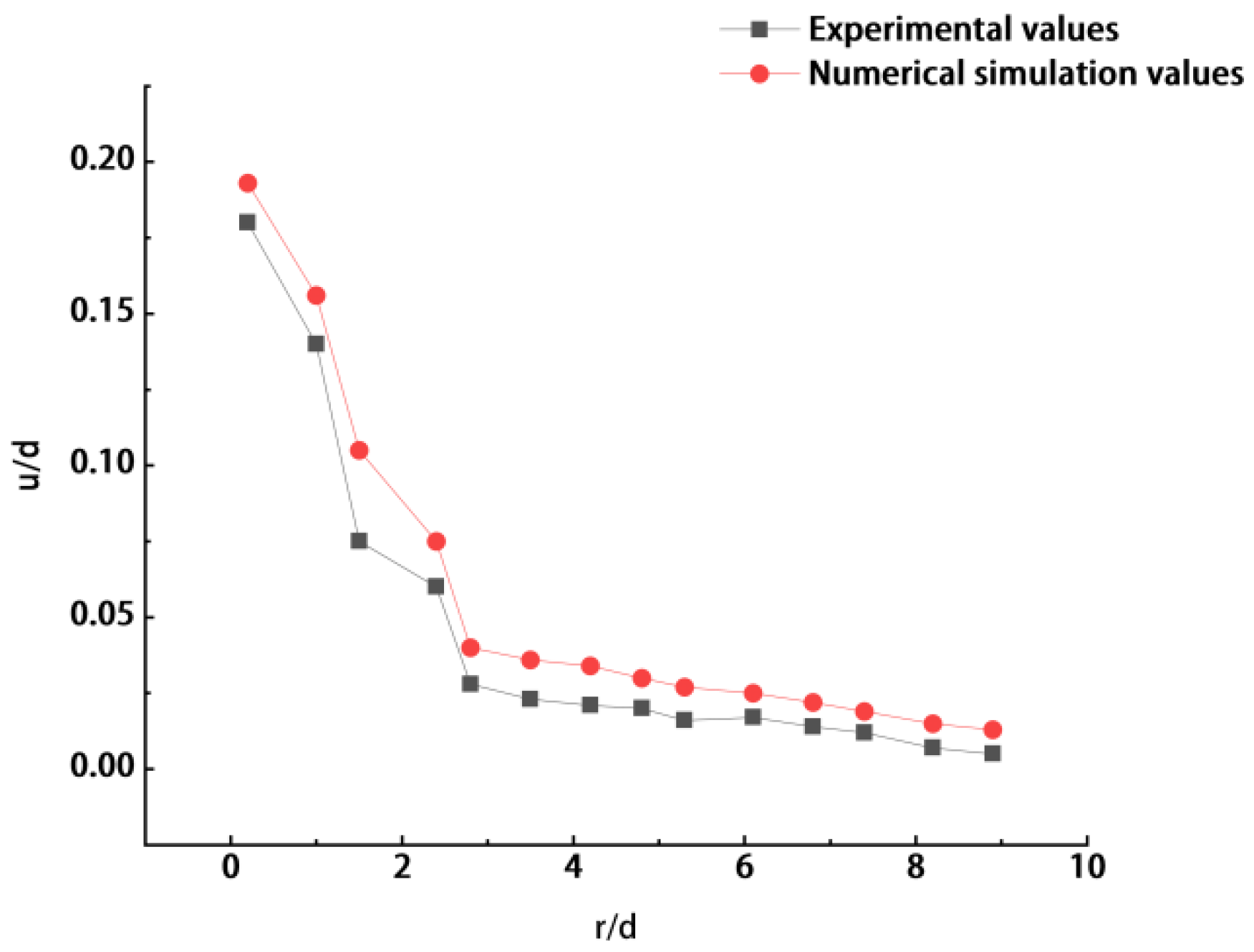
To verify the reliability of the CEL numerical model established in this study, the simulation results were compared with the transparent soil model test data obtained using PIV technology and the predictions of the Cavity Expansion Method (CEM).
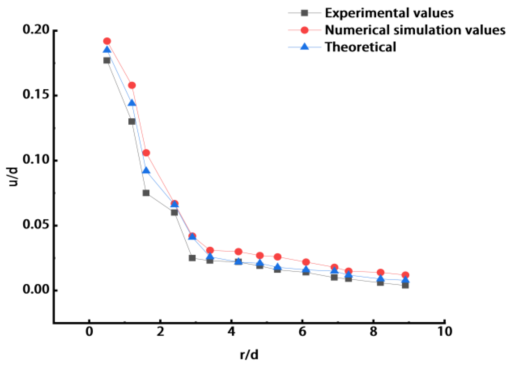
As shown in Figure 4, the displacement attenuation curves obtained by the three methods exhibit a high degree of consistency in their overall shape, all showing a nonlinear trend characterized by a sharp decrease in the near field and a gradual flattening in the far field. To quantitatively evaluate the accuracy of the CEL simulation, n = 15 discrete data points were uniformly extracted along the radial path within the effective range of r/d = 0–9 for statistical error analysis. The statistical indices include the coefficient of determination (R2), root mean square error (RMSE), and maximum relative error (MRE), and their formulas are given as follows:
R 2 = 1 i = 1 n ( y e x p , i y s i m , i ) 2 i = 1 n ( y e x p , i y - e x p ) 2 ,
R M S E = 1 n i = 1 n ( y e x p , i y s i m , i ) 2 ,
M R E = max | y e x p , i y s i m , i | y e x p , i × 100 % ,
where y exp , i is the normalized displacement measured by PIV at the i-th is the corresponding CEL simulated value, and y - exp is the mean value of the experimental measurements. Based on the above calculations, within the near-field strong disturbance zone located within four equivalent radii from the pile center (r/d < 4), the CEL simulation curve agrees very well with the PIV measurements, with the coefficient of determination ( R 2 ) exceeding 0.95. Over the entire domain, the maximum relative error between the CEL simulation results and the experimental data is controlled within 12%, and the root mean square error is only 8%.
More specifically, within the strong disturbance zone located within four equivalent radii from the pile center (r/d < 4), the CEL simulation curve shows good agreement with the PIV measured data. This indicates that the CEL method can accurately capture the soil extrusion behavior under large-deformation conditions. In the far-field region (r/d > 4), the simulated values are slightly lower than the theoretical predictions. This is because the theoretical model assumes the soil to be an infinite half-space, whereas the numerical model is subject to boundary constraints. Nevertheless, the deviation between the two remains within a reasonable range.
Through the quantitative error analysis, the maximum relative error between the CEL simulation results and the experimental data is controlled within 12%, while the root mean square error (RMSE) over the entire computational domain is only 8%. This level of accuracy fully satisfies the requirements of geotechnical numerical analysis, thus demonstrating that the CEL modeling method, parameter selection, and mesh scheme adopted in this study are reasonable and reliable. Therefore, they provide a reliable basis for the subsequent parametric investigation of the smear effect induced by the triangular mandrel shoe. It should be noted that the focus of the experimental–numerical comparison in this study is the consistency of the dimensionless displacement attenuation pattern and the disturbance morphology, and the comparison is based on the normalized variables u/d and r/d. Accordingly, the transparent soil test mainly serves as a kinematic validation rather than a fully scaled prototype simulation strictly satisfying geometric, stress, and time similarity laws. Owing to the limitations of the transparent soil/PIV technique, the validation in this study is mainly concerned with the attenuation behavior of the displacement field, and no direct experimental validation of the stress field has yet been carried out. Therefore, the analysis of stress distribution in this paper is primarily based on the validated displacement results, numerical stability, and consistency with the theoretical response, while direct stress measurements will be pursued in future work.
From the perspective of research methodology, previous studies have shown that cross-validation using multiple experimental or analytical approaches can improve the reliability of engineering conclusions [23]. In the present study, transparent soil/PIV tests, CEL numerical simulation, and the modified Cavity Expansion Method were jointly employed to provide multi-source validation for the evolution of the smear zone induced by the triangular mandrel shoe, thereby enhancing the credibility of the results.

4. Results and Discussion

4.1. Influence of Penetration Rate on Smear Characteristics

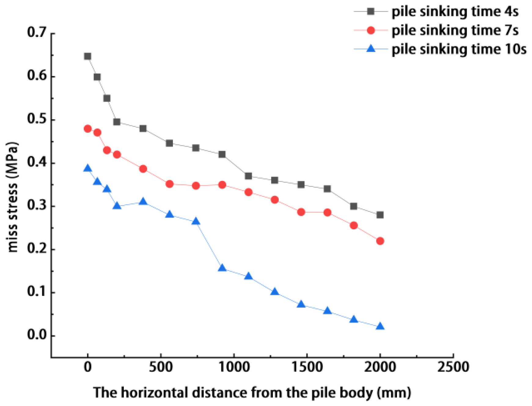
Figure 5 presents the distribution of the effective Mises stress in the surrounding soil along the horizontal direction after the mandrel shoe penetrates to a stable depth. The overall trend of the curves indicates that, under all three cases, the Mises stress exhibits a pronounced nonlinear attenuation with increasing radial distance. In the near-field region adjacent to the mandrel shoe, the stress reaches its peak, indicating severe shear failure and plastic yielding of the soil. As the distance extends toward the far field, the stress gradually decreases and approaches the in situ geostatic stress level of the undisturbed soil. Compared with the slow penetration case, the near-field peak stress in the fast penetration case increases by approximately 42%.
A comparison of the curves under different Installation times shows that the penetration rate has a significant influence on the intensity of the soil stress field. Under the fast penetration case (t = 10 s), the peak stress in the near-field region remains the highest, indicating that the PVD mandrel shoe imposes a stronger instantaneous disturbance on the surrounding soil within a shorter period, causing the soil to reach the yield state more rapidly and to form a more concentrated plastic deformation zone. For the Mohr–Coulomb elastoplastic model adopted in this study, this difference should be understood as a variation in the macroscopic response path of the soil under different loading rates; that is, fast penetration subjects the soil to stronger local shearing before sufficient stress redistribution can occur, thereby resulting in a higher near-field stress level [24].
Moreover, this difference is not limited to the near-field region. In the far field, the fast penetration case still maintains a relatively high residual stress level, indicating that rapid loading not only enhances stress concentration near the mandrel shoe but also increases the ability of the disturbance to propagate outward, thereby expanding the affected range [25]. In contrast, under the slow penetration case (t = 10 s), the soil undergoes a relatively more sufficient process of deformation coordination and stress redistribution during loading, and therefore the overall stress level is lower and the disturbance range is relatively limited.
In summary, a higher penetration rate leads to more pronounced near-field stress concentration and more evident plastic zone expansion, thereby aggravating the structural disturbance within the smear zone. Therefore, in soft soil strata with high sensitivity, the penetration rate should not be determined solely for construction efficiency, but should instead be reasonably selected by comprehensively considering the requirement for controlling disturbance to the surrounding soil.
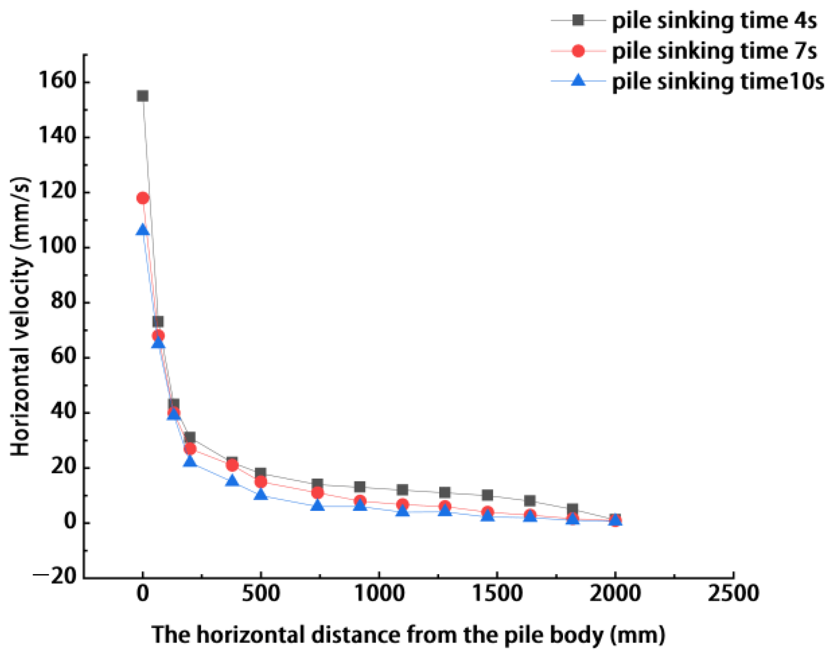
As can be seen from the curves in Figure 6, under different penetration rates, the horizontal soil velocity shows a pattern of rapid attenuation from the near field to the far field. In the region immediately adjacent to the mandrel shoe interface, soil particles are directly pushed by the side wall of the mandrel shoe and therefore attain the maximum initial horizontal velocity. As the radial distance increases, the velocity decreases rapidly under the combined effects of the constraint imposed by the surrounding soil and the energy dissipation associated with plastic deformation and gradually approaches zero in the far field.
A comparison of the different cases shows that the velocity peak is most pronounced under the fast penetration case (t = 4 s), indicating that the mandrel shoe transfers greater momentum to the surrounding soil within a short period and drives the near-field soil to move outward at a higher velocity. In contrast, under the slow penetration case, the peak horizontal soil velocity is significantly lower, indicating that the loading process is milder and the instantaneous kinematic response of the near-field soil is correspondingly suppressed. It should be noted that the Mohr–Coulomb model adopted in this study does not explicitly describe viscous damping. Therefore, the velocity attenuation here should mainly be understood as the result of loading transfer, the constraint of the surrounding soil, and the energy dissipation caused by plastic deformation, rather than as attenuation due to viscous flow in the strict sense.
The attenuation gradient of the curves also reflects differences in disturbance propagation. The curve corresponding to fast penetration decreases more steeply in the near field, indicating that the stronger disturbance is released mainly within a narrow region adjacent to the mandrel shoe. By contrast, the curve under slow penetration attenuates more gently, suggesting that the soil experiences a more sufficient process of deformation coordination under a lower loading rate. Overall, Figure 6 shows that the horizontal velocity field is highly sensitive to the penetration rate: the faster the penetration, the stronger the instantaneous movement of the near-field soil and the larger the affected disturbance range.
Therefore, Figure 6 confirms that the horizontal soil velocity field is highly sensitive to the penetration rate. Fast installation not only causes a sharp increase in the instantaneous velocity of the near-field soil, thereby aggravating the risk of shear damage to the soil skeleton, but also expands the extent of dynamic disturbance. Therefore, in engineering projects with strict disturbance-control requirements, appropriately reducing the installation rate is an effective means of mitigating the transient soil-squeezing effect.
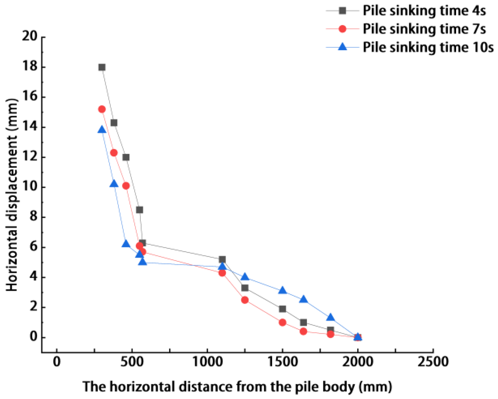
As shown in Figure 7, under different penetration conditions, the horizontal soil displacement exhibits the characteristics of being large in the near field and small in the far field, with a nonlinear attenuation trend as the distance increases. This is consistent with the local soil-squeezing and outward diffusion induced by mandrel shoe penetration. A further comparison shows that, under the fast penetration case (t = 4 s), the horizontal displacement in the near-field region is consistently greater than that under the medium- and slow-penetration cases, and this difference is particularly pronounced in the strong disturbance zone close to the side wall of the mandrel shoe.
This phenomenon indicates that, under rapid penetration, the soil is subjected to stronger local squeezing and shearing within a shorter period, causing a larger volume of soil to accommodate the space occupied by the mandrel shoe through radial displacement, thereby significantly increasing the peak displacement in the near field. In contrast, under slow penetration, the loading process is more gradual, and the soil has a more sufficient process of deformation adjustment, resulting in a smaller cumulative horizontal displacement. The difference observed here mainly reflects the variation in the stress–displacement response and the extent of plastic zone development under different penetration rates and should not be directly interpreted as being governed by rheological or stress-relaxation mechanisms.
Therefore, Figure 7 further indicates that a higher penetration rate enhances the radial displacement response of the soil around the mandrel shoe and consequently enlarges the smear zone. In practical engineering, if strict control of the surrounding deformation is required, the penetration rate should be appropriately reduced so as to mitigate the strong disturbance induced by rapid soil squeezing.

4.2. Influence of Geometric Size on the Smear Zone

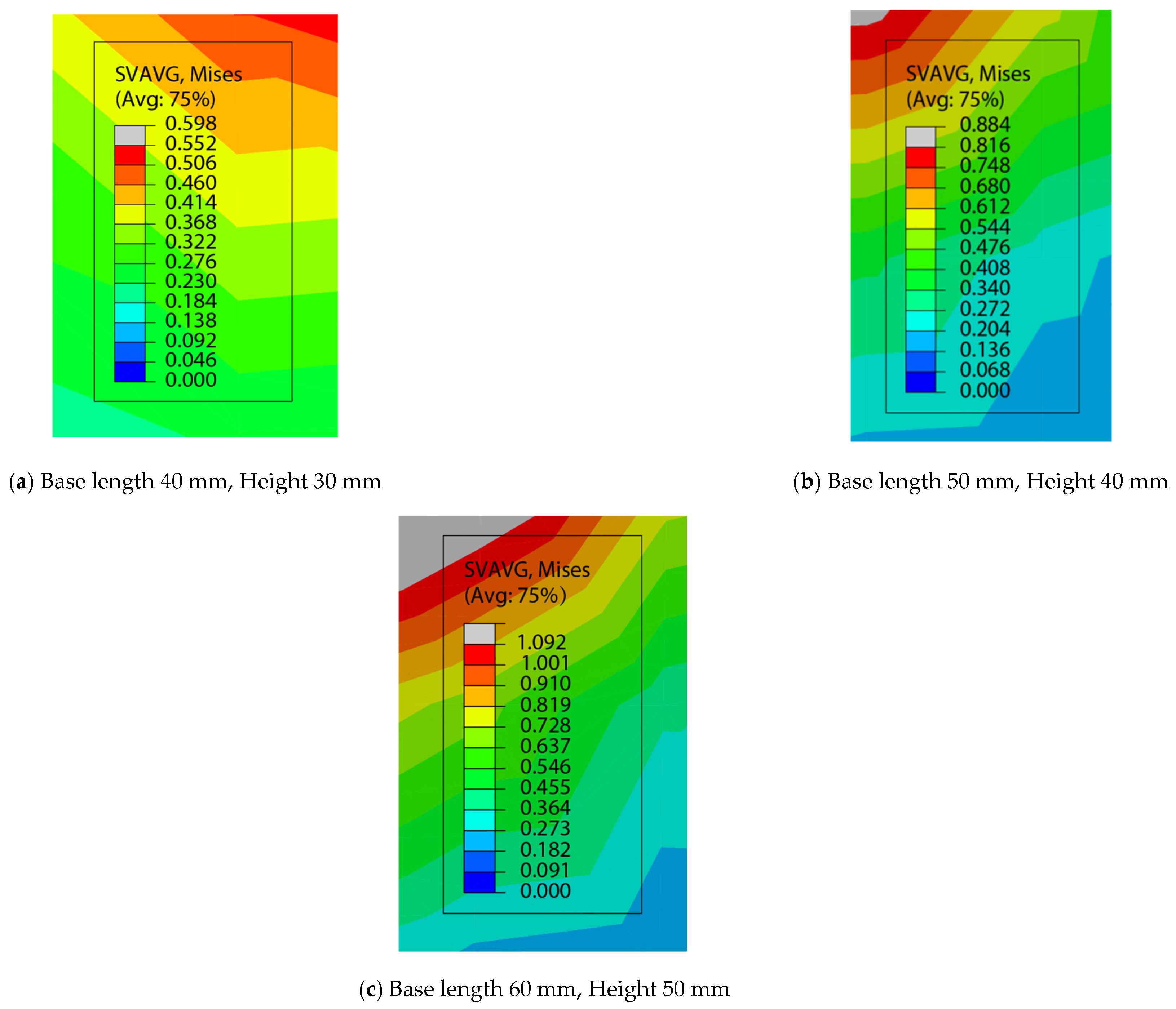
From the distribution characteristics of Mises stress, all cases exhibit significant stress concentration. The high-stress zone is mainly concentrated near the contact interface between the mandrel shoe and the soil, particularly at the vertex positions, indicating that the soil in these locations is subjected to intense shearing. Compared with the straight side edges, the Mises stress at the vertices is markedly higher, and the high-stress zone extends farther outward. This indicates that, during penetration, the sharp corners act as the primary concentration points of stress transfer and cause the most severe damage to the surrounding soil.
A comparison of the contours for different sizes shows that, with the increase in the cross-sectional area of the mandrel shoe, the disturbance range of Mises stress expands significantly. In the small-size case, the red high-stress zone is relatively compact and mainly confined to a limited region around the pile body, while the stress increment in the far-field soil remains small. In contrast, in the large-size case, when the base length increases from 40 mm to 60 mm and the height increases from 30 mm to 50 mm, the area covered by the high-stress zone increases noticeably. The dark-red plastic yield zone expands not only markedly in the vertex direction, but also over a considerable distance in the side direction.
This size effect mainly results from the difference in the volume of displaced soil. The larger the mandrel shoe, the greater the volume of soil that must be displaced during penetration, which forces the surrounding soil to undergo stronger displacement and squeezing and mobilizes soil resistance over a wider range, thereby increasing the overall level of Mises stress. In summary, Figure 8 shows that mandrel shoe size is an important factor affecting the smear effect. Although a larger mandrel shoe is beneficial for improving the cross-sectional utilization of the PVD, it also significantly enlarges the extent of the strong disturbance zone and therefore should be given full consideration in engineering design.
This pattern is generally consistent with previous numerical studies on the control of foundation deformation by structural parameters. Tiutkin et al. [26] pointed out that the layout parameters and stiffness conditions of structural elements can significantly influence soil deformation response. Although their study mainly focused on vertical displacement under service conditions, whereas the present study concerns the stress–displacement evolution and smear zone expansion during penetration, both indicate that structural and mechanical parameters have a significant controlling effect on the extent of soil disturbance. Recent studies on soil–spudcan interaction under complex boundary conditions have also shown that changes in geometric conditions can significantly alter soil stress distribution and failure mechanisms, thereby affecting the spatial extent of disturbance [27].
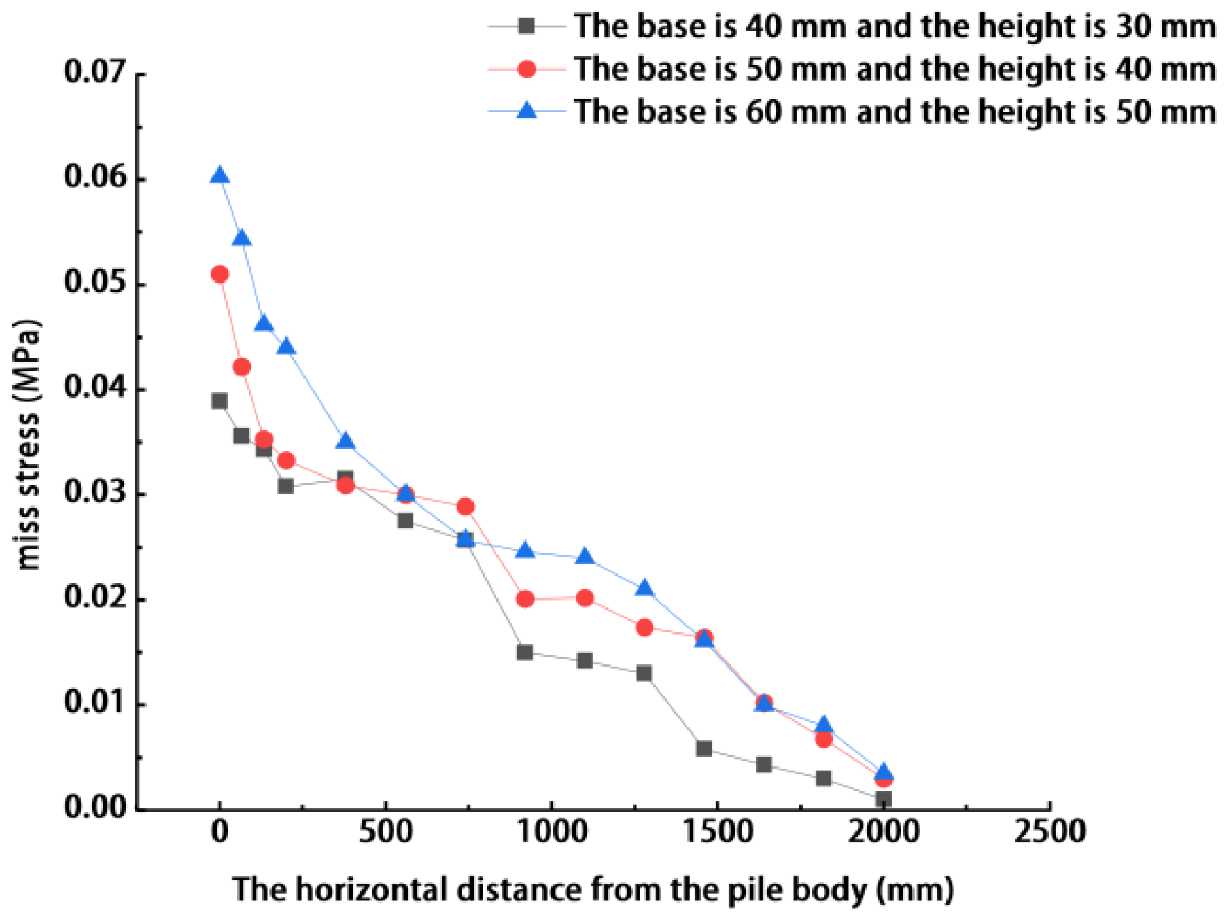
By comparing the positions of the curves for different sizes in Figure 9, a pronounced size effect can be clearly observed. The curve representing the large-size case (base length 60 mm and height 50 mm) remains almost always at the top of the coordinate system, followed by the medium-size case (base length 50 mm and height 40 mm), while the small-size case (base length 40 mm and height 30 mm) lies at the bottom. In quantitative terms, the peak Mises stress induced in the near field by the large mandrel shoe is significantly higher than that induced by the small mandrel shoe. This is because the larger mandrel shoe has a greater cross-sectional area and forces a larger volume of soil to undergo displacement per unit time during penetration, thereby causing a greater accumulation of shear strain energy within the near-field soil skeleton.
Moreover, the size effect is also reflected in the extent of the stress field. From the far-field portion of the curves, it can be seen that the stress in the small-size case attenuates relatively quickly and returns to a low stress level earlier, whereas the curve for the large-size case exhibits a distinct “long-tail” characteristic, maintaining an observable stress increment even at greater distances. This means that, as the size of the mandrel shoe increases, the Mises stress increases not only in magnitude, but also in the outward expansion of its high-stress core zone. Therefore, the data in Figure 9 indicate that mandrel shoe size is a key factor controlling the smear zone. Although large-section mandrel shoes provide higher construction efficiency, the wide high-stress field they generate also increases the risk of disturbance to the surrounding environment.
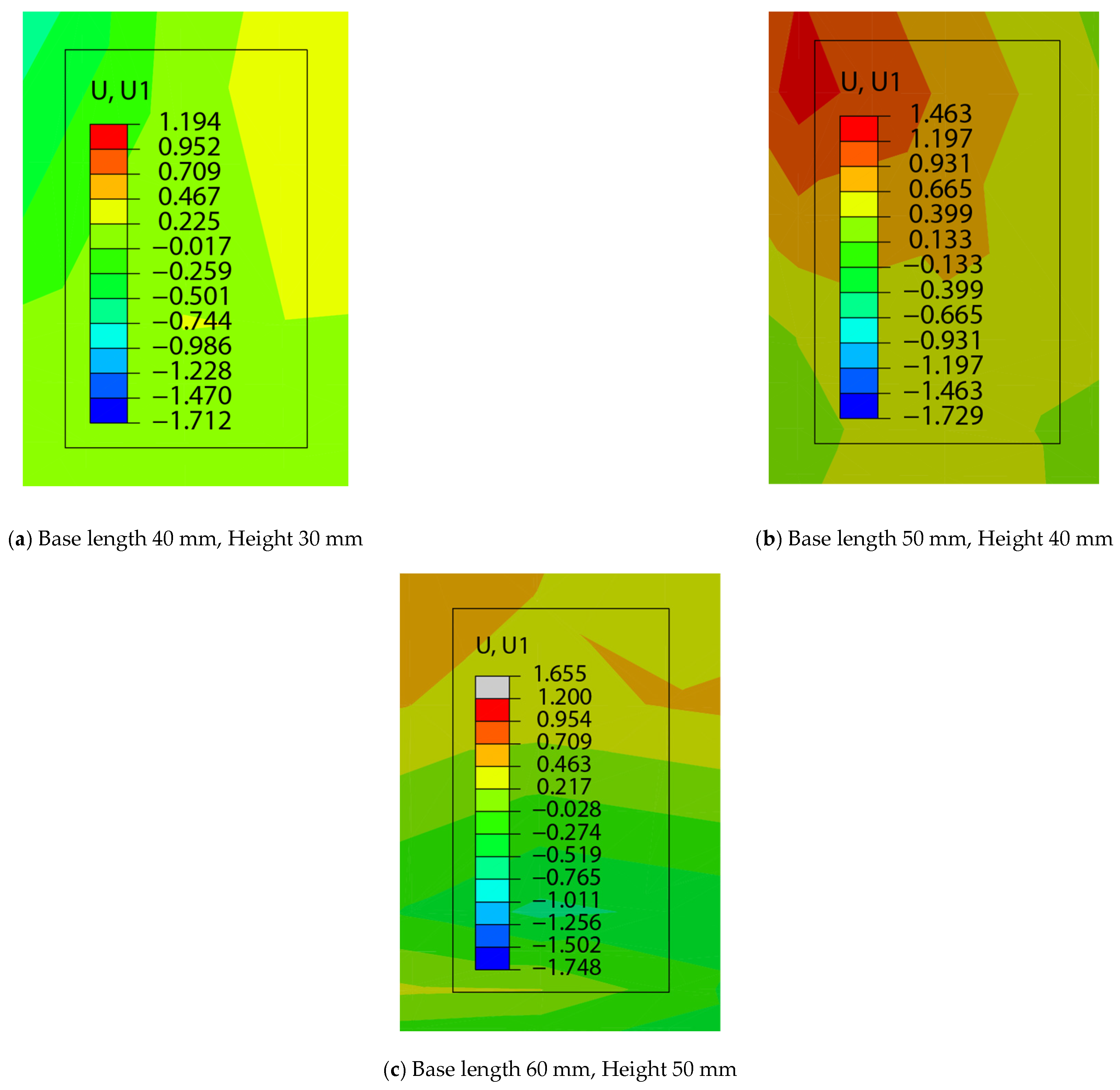
From the overall distribution characteristics of horizontal displacement, soil movement exhibits significant anisotropy. In the vertex direction of the triangle, the dark region representing high displacement extends farthest toward the far field, indicating that the soil in this direction is subjected to the strongest radial thrust. In contrast, the displacement contours along the flat side direction of the triangle are more concentrated and have a smaller influence range. This non-uniform distribution reveals that, during penetration, the sharp corners of the mandrel shoe play the primary role in splitting and displacing the soil, whereas the side portions mainly produce lateral squeezing effects.
A comparison of the contours for different sizes in Figure 10 shows that, as the cross-sectional area of the mandrel shoe increases, the disturbance range of the soil displacement field expands substantially. In the small-size case, the high-displacement zone is mainly concentrated within a short distance around the pile body, while the far-field soil remains essentially stationary. In contrast, in the large-size case, as the volume of displaced soil increases significantly, the boundary of the strong displacement zone moves markedly outward. Not only does the displacement penetration distance in the vertex direction increase substantially, but the disturbance range in the side direction also expands noticeably.
With the increase in size, not only does the displacement of the near-field soil increase sharply, but the affected region in the far field also expands significantly outward. This phenomenon provides an important reference value for determining safe pile spacing in engineering practice.
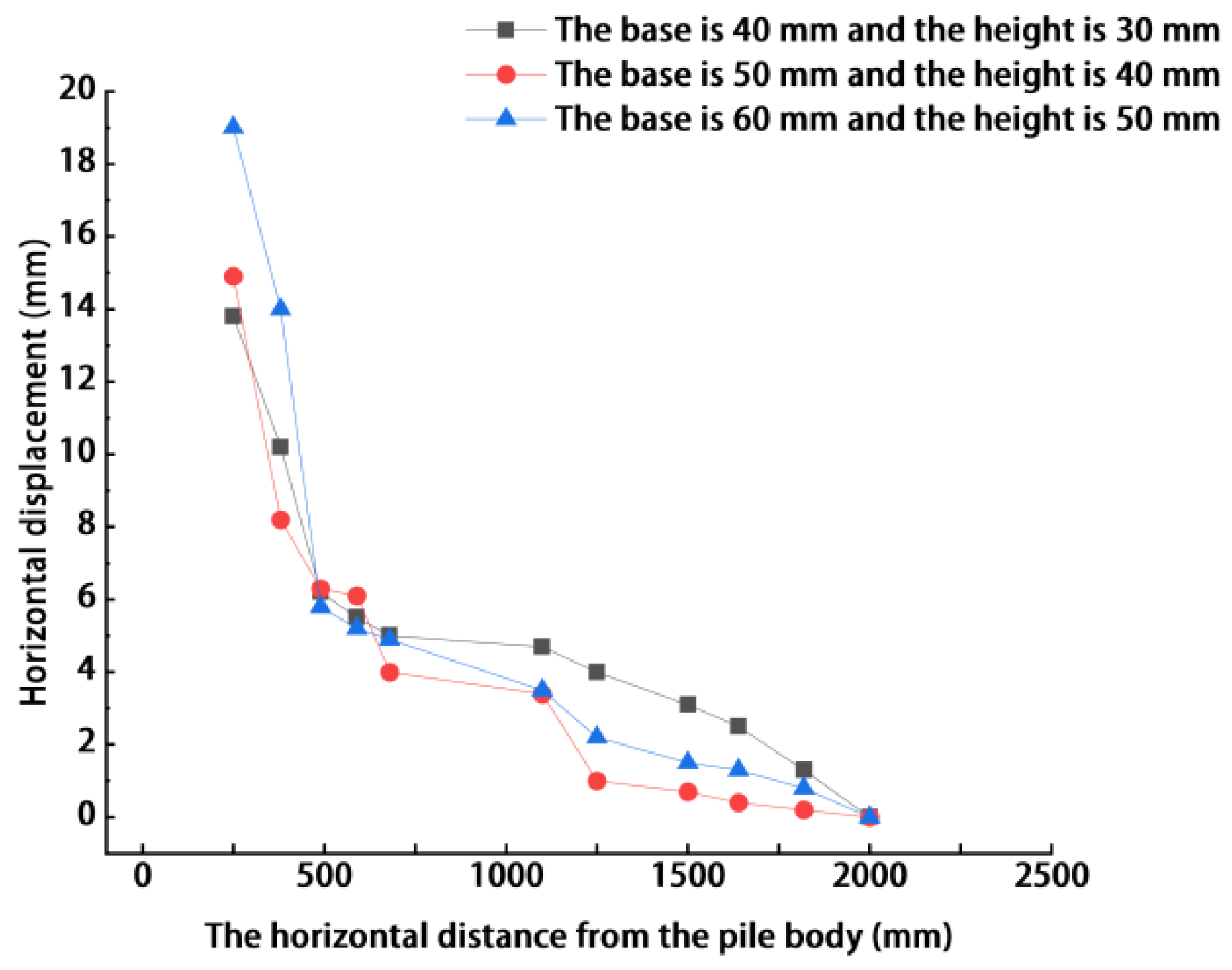
It can be seen from Figure 11 that the cross-sectional size of the mandrel shoe has a pronounced scaling effect on the displacement field. Although the three curves follow similar attenuation trends, they exhibit clear stratification in magnitude along the vertical axis. The curve for the large-size case remains at the top throughout the 500 mm range, maintaining a distinct gap from that of the small-size case. In the vicinity of the pile–soil interface, the initial displacement peak induced by the large mandrel shoe is the highest, which directly corresponds to its largest equivalent displaced-soil radius. In the far field, the curve for the large-size case attenuates relatively gently and still shows a considerable influence.
The differences in the curve shapes reveal the nonlinear characteristics of the size effect: as the mandrel shoe size increases, the squeezing-induced displacement of the soil at the contact interface becomes more pronounced, while the influence on the far field also remains considerable.
In engineering design, the influence range of a large mandrel shoe cannot be simply extrapolated linearly from the results of a small mandrel shoe. The dual effect of larger cross-sectional dimensions, namely, the enhancement of near-field disturbance and the outward expansion of far-field influence, must be fully taken into account. Therefore, provided that the requirements for structural strength and construction stiffness are satisfied, the size of the mandrel shoe should not be increased without control. For a triangular mandrel shoe, particular attention should also be paid to the fact that the disturbance in the vertex direction is greater than that in the side direction. In cases where PVDs are densely installed, the spacing of PVDs should be reasonably checked by considering the size of the mandrel shoe and the corresponding increase in disturbance radius, and a sufficient safety margin should be reserved.

4.3. Influence of Soil Parameters on the Smear Zone

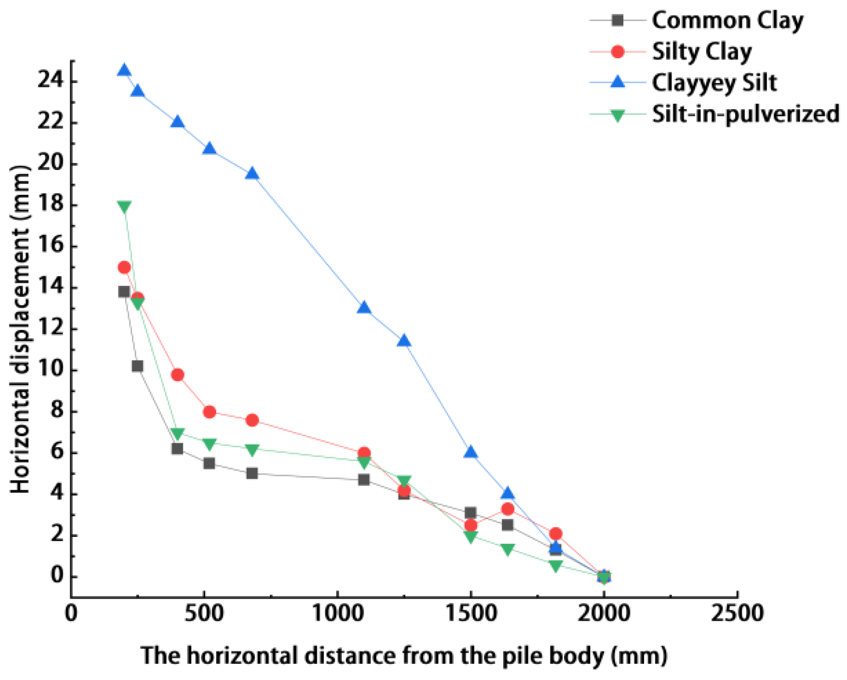
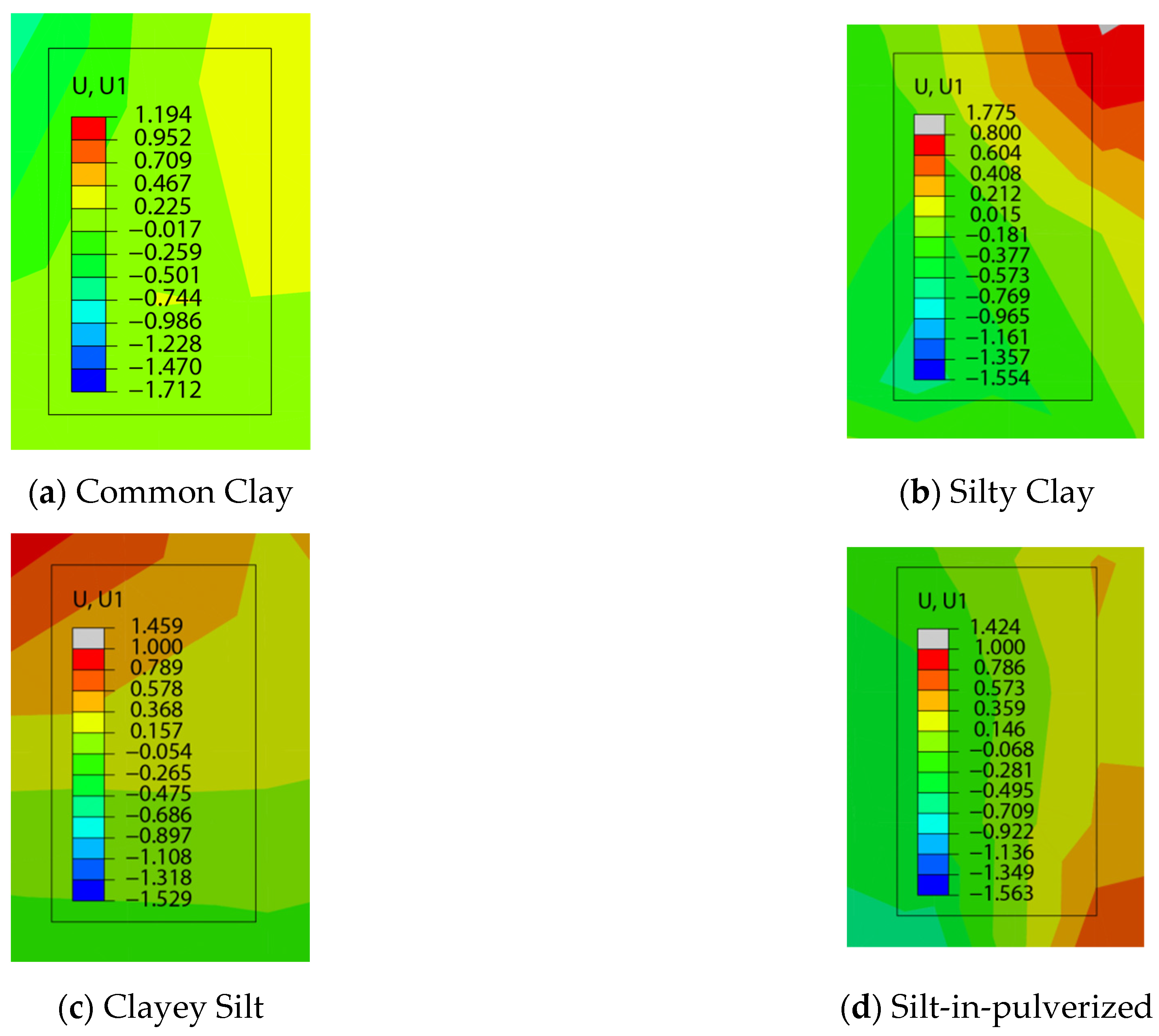
The controlling mechanisms of soil parameters on horizontal displacement diffusion, Mises stress concentration, and the extent of the smear zone defined by displacement attenuation are not exactly the same; therefore, the ranking of these three responses is not necessarily identical. As shown in Figure 12, the influence range of horizontal displacement varies significantly under different soil conditions, among which Clayey Silt exhibits the largest disturbance range. This indicates that, under the parameter settings given in Table 3, Clayey Silt is more sensitive to the outward transmission of disturbance induced by mandrel shoe penetration. According to Table 3, Common Clay has a relatively high elastic modulus, cohesion, and internal friction angle, and therefore provides stronger confinement to the local displacement diffusion caused by mandrel shoe penetration, resulting in the smallest displacement response range. The responses of Silt-in-pulverized and Silty Clay fall between these two extremes, indicating that the differences in soil strength, stiffness, and structural characteristics are important intrinsic factors controlling the extent of smear zone expansion [28].
Figure 13 illustrates the radial evolution of horizontal displacement under different soil conditions. The results show that the displacement decreases sharply and nonlinearly with increasing radial distance, and that this attenuation behavior is mainly governed by the geometric characteristics of the mandrel shoe. Specifically, the region extending approximately 60 mm outward from the outer edge of the sleeve is identified as the significant smear zone, within which the displacement decreases by as much as 50–70%, which agrees well with the extent of soil remolding induced by mandrel shoe penetration. Beyond this range, the displacement curves gradually flatten, indicating that the soil response has transitioned from the initial stage of plastic failure to a later stage of weak structural self-adjustment.
Under different soil parameter conditions, Clayey Silt corresponds to the widest smear zone, approximately nine times the sleeve diameter, which is consistent with the relatively large displacement influence range observed in Figure 12. By contrast, Common Clay exhibits the smallest smear zone, reflecting the restraining effect of its relatively high stiffness and strength parameters on disturbance propagation. Specifically, the disturbance range of Common Clay is the smallest, at approximately six times the sleeve diameter, owing to its higher cohesion. The responses of Silty Clay and Silt-in-pulverized lie between these two cases. In addition, the tip geometry of the triangular mandrel shoe leads to local stress concentration, thereby aggravating the structural damage to the soil in the vicinity of the tip. These observations further confirm that the smear effect is jointly controlled by the geometric parameters of the mandrel shoe and the properties of the soil.
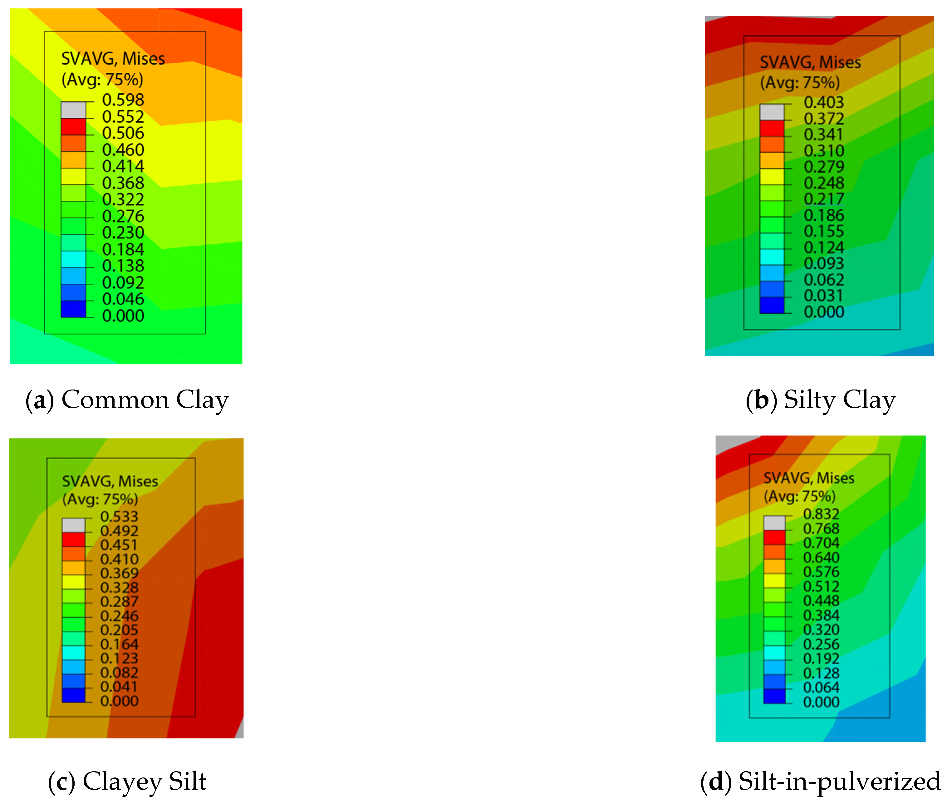
As shown in Figure 14, Silt-in-pulverized exhibits the highest peak Mises stress, indicating that this type of soil can accumulate a higher level of deviatoric stress during mandrel shoe penetration. This is mainly related to its internal particle composition and skeleton effect: the presence of silt enhances interparticle interlocking and frictional resistance, enabling the soil to sustain higher local shear stress before significant plastic deformation occurs, and thus results in more pronounced stress concentration. In contrast, Silty Clay shows the lowest level of Mises stress, indicating that, under the parameter settings given in Table 3, its relatively low elastic modulus and internal friction angle make it more likely to release stress through local deformation in the near field, thereby making it difficult to maintain high stress accumulation. The stress levels of Common Clay and Clayey Silt lie between these two extremes, indicating that the strength parameters and structural characteristics of different soil types jointly control the degree of stress concentration and the mode of disturbance zone expansion during mandrel shoe penetration. The differences observed here should be attributed to the differences in strength-controlled responses under different soil parameter conditions.
The stress levels of Common Clay and Clayey Silt are intermediate. This suggests that the cohesion of Common Clay provides relatively strong stress support within the constitutive framework adopted in this study, thereby maintaining a relatively stable stress transfer. Although Clayey Silt contains silt particles, its overall structural strength under the present parameter setting is slightly lower than that of Common Clay, resulting in a relatively lower yielding threshold.
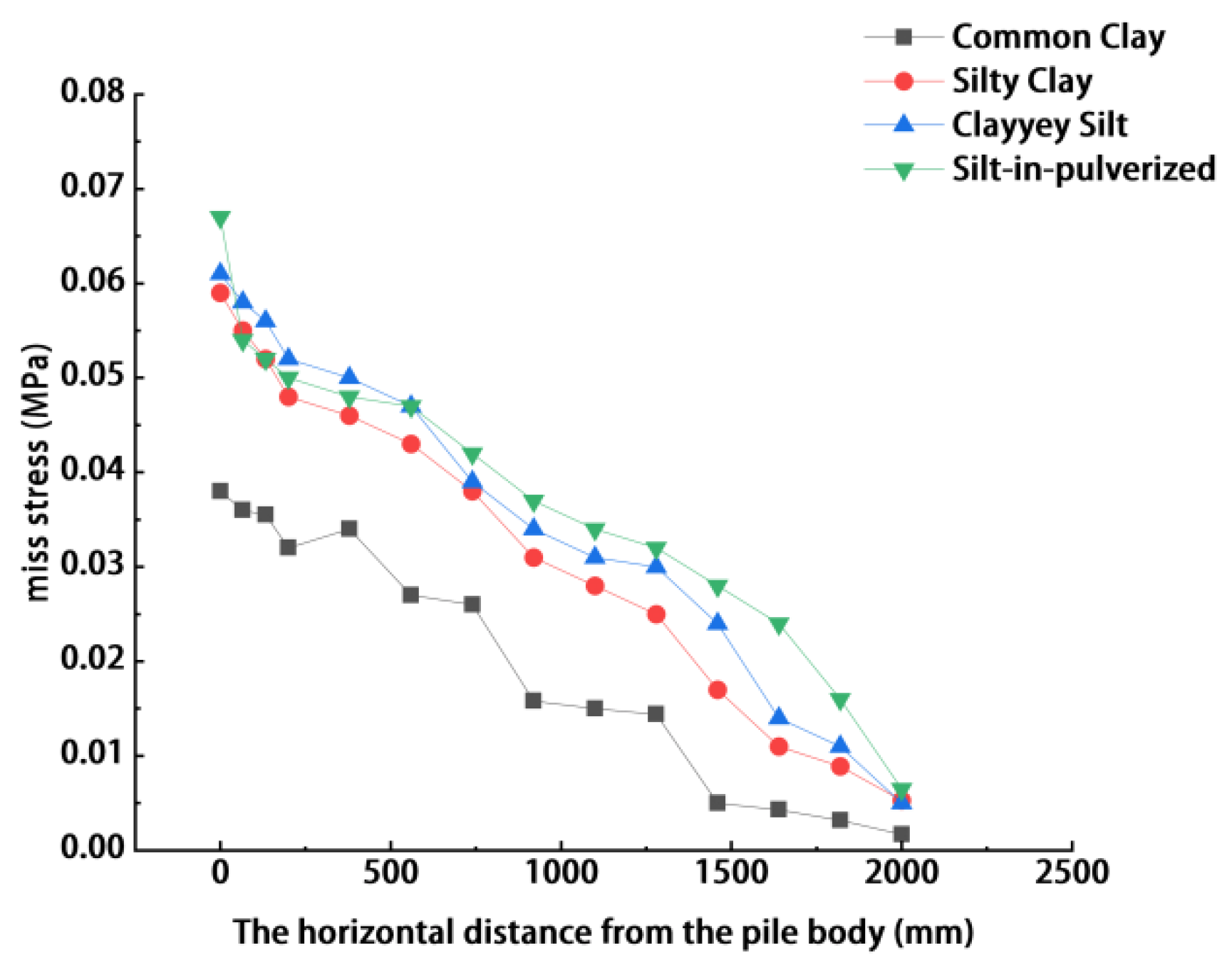
Figure 15 presents the horizontal evolution of Mises stress under different soil conditions. The results show that the stress distributions of all soil types exhibit a pronounced nonlinear decreasing trend. The high-stress concentration zone is located immediately adjacent to the edge of the mandrel shoe, and its disturbance range extends far beyond the geometric scale of the mandrel shoe itself, which strongly confirms the objective existence of the smear effect. In particular, within the near-field region ranging from 0 to 250 mm from the pile body, the stress gradient changes sharply, forming a distinct high-stress core zone.
Soil type has a significant influence on the spatial distribution of the smear zone. Under the cases analyzed in this study, Clayey Silt corresponds to the largest smear zone, whereas Common Clay corresponds to the smallest, with Silt-in-pulverized and Silty Clay lying between these two extremes. This result indicates that the strength parameters, stiffness level, and structural confinement capacity of the soil are key factors controlling the disturbance range induced by mandrel shoe penetration. In general, soils with lower strength, lower stiffness, and a greater tendency for plastic expansion are more likely to develop a wider disturbance zone. In contrast, soils with higher stiffness and strength and stronger structural confinement can restrict the disturbance within a relatively limited range [29]. It should be noted that the displacement diffusion range and the smear zone defined on this basis mainly characterize the outward propagation capacity of the disturbance, whereas the peak Mises stress more directly reflects the degree of local stress concentration in the near field. Therefore, the ranking of different soil types does not necessarily remain the same across all response indicators. Overall, the pile–soil interaction during mandrel shoe penetration governs the formation and evolution of the smear zone. These findings not only provide a theoretical basis for mandrel shoe geometry optimization and construction parameter control, but also offer useful guidance for PVD layout and improvement of consolidation efficiency in soft ground treatment.


5. Theoretical Analysis

5.1. Limitations of Traditional Cavity Expansion Theory

Cavity Expansion Method (CEM) is a classical theoretical tool in geotechnical engineering for analyzing the soil-squeezing effect induced by pile penetration. Based on the axisymmetric assumption, this theory idealizes the mandrel shoe as a cylindrical cavity in an infinite medium and assumes the soil to be an ideal elastoplastic material obeying the Mohr–Coulomb yield criterion. According to Vesic’s expansion theory, under undrained conditions, the following analytical relationship exists between the plastic zone radius   R p and the expansion radius r u (i.e., the equivalent radius of the mandrel shoe, r e q ):
R p r e q = I r sec ϕ 1 1 + I r Δ 1 2 ,
where I r is the rigidity index ( I r = E/[2(1 + v ) S u )], ϕ is the effective internal friction angle, and Δ is the average volumetric strain.
However, the numerical simulation results show that the stress field and displacement field generated by the triangular mandrel shoe exhibit significant geometric corner effects. In the vertex direction of the triangle, the soil is subjected to the strongest splitting and squeezing actions, and the disturbance range is significantly larger than the average value predicted by the theoretical calculation; in contrast, in the side direction, the disturbance range is relatively smaller. If the CEM based on an equivalent-area circle is directly adopted, the differences in different directions cannot be distinguished, and the failure range at the vertices is often underestimated, thereby introducing potential safety risks in engineering design. Therefore, the traditional theory must be modified by introducing a shape factor that reflects the geometric characteristics of the cross-section.

5.2. Introduction and Definition of the Shape Correction Factor

To quantify the influence of the geometric corners of the triangular mandrel shoe on the extent of the smear zone, a shape correction factor (ξ) is introduced in this study based on the traditional Cavity Expansion Method. The shape correction factor ξ is not a purely empirical fitting parameter; rather, it is a semi-empirical correction factor used to characterize the amplification or reduction in directional disturbance caused by the corner effect of the triangular mandrel shoe. Its physical basis lies in the stronger stress concentration and soil-squeezing effect in the vertex direction, whereas the disturbance in the side direction is relatively weaker. Assuming that the modified plastic zone boundary (i.e., the boundary of the smear zone), R p , θ , varies with the polar angle θ, the correction formula can be expressed as
R p , θ = ξ θ R p , C E M .
R p , C E M is the theoretical plastic zone radius calculated on the basis of the equivalent circular area. According to the anisotropic characteristics revealed by the numerical simulation, the shape correction factor is decomposed into two components corresponding to two key directions:
Vertex Correction Factor ( ε t i p ): corresponding to the three vertex directions of the triangle (i.e., polar angles θ = 0°, 120°, and 240°), where the stress concentration is the strongest.
Side Correction Factor ( ε s i d e ): corresponding to the midpoint directions of the three straight sides of the triangle (i.e., polar angles θ = 60°, 180°, and 300°), where the squeezing effect is relatively weaker.

5.3. Parameter Back-Analysis Based on Numerical Results

Based on the above geometric and mechanical understanding, the shape correction factor ξ was further calibrated in this study using the CEL numerical results. Taking the large mandrel shoe with a base length of 60 mm and a height of 50 mm as an example, the numerical simulation shows that the plastic failure radius in the vertex direction, R p , n u m t i p , is approximately 8.5 times the equivalent radius of the mandrel shoe, whereas that in the side direction, R p , n u m s i d e , is approximately 5.2 times the equivalent radius.
By substituting the same soil parameters into the CEM theoretical calculation, the theoretical ratio of plastic zone radius to equivalent radius, R p / r e q , is approximately 6.4. Accordingly, the correction factors under this condition can be obtained as follows:
Vertex direction correction factor ξ t i p 1.33 .
Side direction correction factor ξ s i d e 0.81 .
A comprehensive analysis of the data for the small-size and medium-size mandrel shoes shows that, although the absolute disturbance radius increases with increasing size, the normalized correction factor ξ remains relatively stable. In soft clay, the value of E t i p generally ranges from 1.25 to 1.35, whereas E s i d e ranges from 0.80 to 0.85. This indicates that, at the vertices of the triangular mandrel shoe, the disturbance range is on average about 30% larger than that predicted by the equivalent circular cavity expansion theory, while in the side direction it is reduced by about 20%.

5.4. Validation and Analysis of the Modified Theory

To examine the applicability and accuracy of the proposed modified model for predicting the smear zone of the triangular mandrel shoe, a systematic comparison was carried out with the three-dimensional numerical simulation results based on CEL and the transparent soil–PIV experimental data presented in this study.
As shown in Figure 16, the normalized displacement curves (u/d–r/d) obtained by the three methods exhibit a high degree of consistency in both the near field and the far field, with only slight deviations. The overlap of the three curves in shape indicates that both the modified theoretical model proposed in this study and the numerical simulation can accurately capture the deformation behavior of the soil under large-deformation conditions. Using the same statistical error indices defined in Section 3.4, discrete-point comparisons were carried out among the theoretical predictions, the CEL numerical simulation results, and the PIV experimental data. Quantitative analysis based on the extracted data points shows that the maximum relative error among the three datasets is 12%, while the root mean square error (RMSE) is approximately 8%, both of which fall within the range acceptable for engineering applications. This demonstrates that the modified theoretical model has high predictive accuracy and reliability. Because the modified theory is established on the basis of the geometric anisotropy of the triangular mandrel shoe, the comparison shown in Figure 16 was strictly performed using data extracted along the vertex direction. This direction is the key direction in which stress concentration is the most intense and the soil-squeezing effect is the most pronounced. Therefore, cross-validation in this direction best demonstrates the rigor and effectiveness of the modified theory in dealing with non-axisymmetric problems. The slight differences among the curves are mainly attributed to the idealized assumptions introduced in the modified theoretical model for computational simplification, the weak constraint imposed by the boundary conditions of the experimental setup on far-field displacement, and the systematic errors associated with PIV image recognition. In summary, the differences in the smear zone boundary predicted by the three methods are very small, indicating that the modified theoretical model can effectively reflect the actual spatial extent of the smear zone. In addition, the modified theoretical model is computationally efficient and convenient, making it suitable for preliminary assessment at the engineering design stage and providing reliable theoretical support for practical applications.

6. Conclusions

This study systematically investigated the effects of the penetration rate, geometric characteristics, and soil parameters of a triangular mandrel shoe on the smear effect and analyzed the problem using a combined framework of the Coupled Eulerian–Lagrangian (CEL) method and the cavity expansion theory with introduced shape correction factors. The main conclusions are as follows:
(1) The penetration rate has a significant influence on the stress field and displacement field of the soil surrounding the triangular mandrel shoe. As the penetration rate increases, the instantaneous disturbance in the near field becomes stronger, making the soil more prone to stress concentration and plastic zone expansion, which leads to a marked increase in the near-field peak stress. When the penetration condition changes from slow to fast, the near-field peak stress increases by approximately 42%. Meanwhile, rapid penetration also enhances the outward propagation capacity of the disturbance, causing the far-field displacement and the extent of the smear zone to increase simultaneously.
(2) An increase in mandrel shoe size significantly amplifies the geometric corner effect of the triangular cross-section, resulting in a rapid nonlinear outward expansion of the strong smear zone. The near-field disturbance range of the large mandrel shoe is 21% greater than that of the small mandrel shoe. The vertex direction of the triangle serves as the main channel for stress concentration and displacement extrusion, exhibiting a pronounced “splitting–penetration” mechanism. As the size increases, the anisotropic disturbance becomes more evident, and the stress concentration and displacement splitting effects in the vertex direction are further enhanced, causing the disturbance range in this direction to far exceed that in the side direction.
(3) The physical and mechanical properties of different soils play an important controlling role in the evolution of the smear effect. Under the cases considered in this study, Clayey Silt exhibits the largest displacement influence range and the largest smear zone defined by displacement attenuation, whereas Common Clay shows the smallest. In contrast, the peak Mises stress is relatively high in Silt-in-pulverized and relatively low in Silty Clay, indicating that different response indicators are not controlled by the same combination of soil parameters in exactly the same manner. This demonstrates that the strength parameters, stiffness level, and structural integrity of the soil jointly determine the expansion pattern and influence range of the smear zone during mandrel shoe penetration.
(4) The predictive formula for the plastic zone radius established on the basis of the shape correction factor agrees well with the CEL numerical results and can effectively reflect the displacement amplification in the vertex direction and the anisotropic disturbance characteristics of the triangular mandrel shoe. The modified theory successfully quantifies the amplification effect in the vertex direction relative to the prediction of the equal-area circular theory, thereby providing a theoretical basis for the structural optimization of irregular mandrel shoes and the design of construction parameters for PVD installation in soft ground. It should be noted that the conclusions of this study are established on the basis of the Mohr–Coulomb elastoplastic model and are mainly applicable to problems dominated by strength control and plastic disturbance. If soil viscosity, creep behavior, and time-dependent rheological characteristics are to be further described, it will still be necessary to introduce visco-elastoplastic or viscoplastic constitutive models in future studies.

Author Contributions

J.L. contributed to conceptualization, methodology, formal analysis, investigation, data curation, visualization, funding acquisition, and writing—review and editing. Z.Y. was responsible for investigation, software, validation, resources, and writing—original draft. Z.L. contributed to conceptualization, methodology, supervision, project administration, and writing—review and editing. Y.T. contributed resources, validation, and writing—review and editing. All authors made substantial contributions to this research and approved the final manuscript version. All authors have read and agreed to the published version of the manuscript.

Funding

This research was funded by the project ‘Research on Key Technologies and Construction Control of Vacuum-Surcharge Combined Preloading for Soft Ground Treatment in Nearshore Land Reclamation Engineering (Construction of Section 3b, Land Reclamation Project for Shenzhen Marine Emerging Industry Base)’. Funding Agency: Guangzhou Salvage Bureau. Funding Number: GL-GH-20-SZHY3b-YJFB01.

Data Availability Statement

Data are contained within the article. The data presented in this study can be requested from the authors.

Conflicts of Interest

All authors declare that this study was conducted without any commercial or financial relationships that could be perceived as a potential conflict of interest.

References

  1. Indraratna, B.; Rujikiatkamjorn, C.; Balasubramaniam, A.S.; McIntosh, G. Soft Ground Improvement via Vertical Drains and Vacuum Assisted Preloading. Geotext. Geomembr. 2012, 30, 16–23. [Google Scholar] [CrossRef]
  2. Shen, Z.; Chian, S.C.; Tan, S.A.; Leung, C.F. Modelling Smear Effect of Vertical Drains Using a Diameter Reduction Method. J. Rock Mech. Geotech. Eng. 2024, 16, 279–290. [Google Scholar] [CrossRef]
  3. Prabavathy, S.; Rajagopal, K.; Pitchumani, N. Investigation of Smear Zone Around PVD Mandrel Using Image-Based Analysis. Int. J. Geosynth. Ground Eng. 2021, 7, 94. [Google Scholar] [CrossRef]
  4. Iskandar, R.; Tarigan, A.P.M.; Roesyanto. A Review on the Characteristics of the Smear Zone: Field Data Back Calculation Compared with Laboratory Testing. Open Civ. Eng. J. 2018, 12, 340–354. [Google Scholar] [CrossRef]
  5. Adriyati, M.; Yasufuku, N.; Ishikura, R.; Wu, X.; Rifa’i, A. Improved Mandrel System for Prefabricated Vertical Drain Installation: A Macro to Micro Analysis. Appl. Sci. 2023, 13, 6673. [Google Scholar] [CrossRef]
  6. Ghandeharioon, A.; Indraratna, B.; Rujikiatkamjorn, C. Analysis of Soil Disturbance Associated with Mandrel-Driven Prefabricated Vertical Drains Using an Elliptical Cavity Expansion Theory. Int. J. Geomech. 2010, 10, 53–64. [Google Scholar] [CrossRef]
  7. Tian, Y.; Wu, W.B.; Wen, M.J.; Jiang, G.S.; El Naggar, M.H.; Mei, G.X. Nonlinear Consolidation of Soft Foundation Improved by Prefabricated Vertical Drains Based on Elliptical Cylindrical Equivalent Model. Int. J. Numer. Anal. Methods Geomech. 2021, 45, 1949–1971. [Google Scholar] [CrossRef]
  8. Tian, Y.; Jiang, G.S.; Wu, W.B.; Wen, M.J.; Mei, G.X. Elliptical Cylindrical Equivalent Model for Consolidation of Unsaturated Soil Improved by PVD. Int. J. Numer. Anal. Methods Geomech. 2022, 46, 3123–3153. [Google Scholar] [CrossRef]
  9. Ghandeharioon, A.; Indraratna, B.; Rujikiatkamjorn, C. Laboratory and Finite-Element Investigation of Soil Disturbance Associated with the Installation of Mandrel-Driven Prefabricated Vertical Drains. J. Geotech. Geoenviron. Eng. 2012, 138, 295–308. [Google Scholar] [CrossRef]
  10. Lin, J.; Zhang, B.; Liang, Z.; Chen, H.; Yang, Z.; Tang, Y.; Du, Y. Visualization Study on Construction Disturbance of Drainage Board Sleeve Pile Shoes. Buildings 2025, 15, 4195. [Google Scholar] [CrossRef]
  11. Yin, Q.; Dong, S.; Jiang, F.; Guedes Soares, C. Spudcan Penetration Simulation Using the Coupled Eulerian-Lagrangian Method with Thermo-Mechanical Coupled Analysis. J. Ocean Univ. China 2019, 18, 317–327. [Google Scholar] [CrossRef]
  12. Wang, D.; Bienen, B.; Nazem, M.; Tian, Y.; Zheng, J.; Pucker, T.; Randolph, M.F. Large Deformation Finite Element Analyses in Geotechnical Engineering. Comput. Geotech. 2015, 65, 104–114. [Google Scholar] [CrossRef]
  13. Thielicke, W.; Stamhuis, E.J. PIVlab—Towards User-Friendly, Affordable and Accurate Digital Particle Image Velocimetry in MATLAB. J. Open Res. Softw. 2014, 2, e30. [Google Scholar] [CrossRef]
  14. Zhang, W.; Gu, X.; Zhong, W.; Ma, Z.; Ding, X. Review of Transparent Soil Model Testing Technique for Underground Construction: Ground Visualization and Result Digitalization. Undergr. Space 2022, 7, 702–723. [Google Scholar] [CrossRef]
  15. Thielicke, W.; Sonntag, R. Particle Image Velocimetry for MATLAB: Accuracy and Enhanced Algorithms in PIVlab. J. Open Res. Softw. 2021, 9, 12. [Google Scholar] [CrossRef]
  16. Iskander, M.; Bathurst, R.J.; Omidvar, M. Past, Present, and Future of Transparent Soils. Geotech. Test. J. 2015, 38, 557–573. [Google Scholar] [CrossRef]
  17. Liu, J.; Iskander, M. Modelling Capacity of Transparent Soil. Can. Geotech. J. 2010, 47, 451–460. [Google Scholar] [CrossRef]
  18. Ezzein, F.M.; Bathurst, R.J. A Transparent Sand for Geotechnical Laboratory Modeling. Geotech. Test. J. 2011, 34, 590–601. [Google Scholar] [CrossRef]
  19. Almikati, A.; Pierozan, R.C.; Sadek, S.; Zornberg, J.G. Geotechnical Characterization of Laponite as Transparent Clay Surrogate. Geotech. Test. J. 2023, 46, 20220106. [Google Scholar] [CrossRef]
  20. Karmaker, R.; Hawlader, B.; Perret, D.; Dey, R. Numerical Modelling of Pile Jacking in Highly Sensitive Clays. Can. Geotech. J. 2024, 61, 2597–2614. [Google Scholar] [CrossRef]
  21. Robert, D.J. A Modified Mohr–Coulomb Model to Simulate the Behavior of Pipelines in Unsaturated Soils. Comput. Geotech. 2017, 91, 146–160. [Google Scholar] [CrossRef]
  22. Qiu, G.; Henke, S.; Grabe, J. Application of a Coupled Eulerian–Lagrangian Approach on Geomechanical Problems Involving Large Deformations. Comput. Geotech. 2011, 38, 30–39. [Google Scholar] [CrossRef]
  23. Lukpanov, R.E.; Yenkebayev, S.B.; Tsigulyov, D.V. Assessment of the Bearing Capacity of Piles in Soil, Determined by Static and Dynamic Load Tests. Eng. J. Satbayev Univ. 2021, 143, 252–260. [Google Scholar] [CrossRef]
  24. Robinson, S.; Brown, M.J.; Knappett, J.; Brennan, A.; Duran Caballero, D.; Arroyo, M. The Variation of Large Strain Viscous Rate Effects from Undrained Triaxial Element Testing of Kaolin Clay. Acta Geotech. 2025. published online. [Google Scholar] [CrossRef]
  25. Liu, K.; Wang, D.; Zheng, J. Numerical Investigation of Spudcan Penetration under Partially Drained Conditions. Ocean Eng. 2022, 244, 110425. [Google Scholar] [CrossRef]
  26. Tiutkin, O.; Radkevych, A.; Dubinchyk, O.; Kharchenko, V. Parametric Analysis of a Strain State of a Soil Base Strengthened with Vertical Elements. Min. Miner. Depos. 2024, 18, 104–112. [Google Scholar] [CrossRef]
  27. Lei, Z.; Zeng, G.; Ren, H.; Wu, B.; Jie, Y. Effect of the Sloping Seabed on 3D Soil–Spudcan Interaction Using a Material Point–Finite Element (MPM-FEM) Model. J. Rock Mech. Geotech. Eng. 2024, 16, 1436–1454. [Google Scholar] [CrossRef]
  28. Wang, B.; Huang, Y.; Zhu, E.; Xiao, X.; Wu, Q. Experimental Study on the Thixotropic Strength of the Marine Soft Clay from the Yangtze River Estuary. Front. Mar. Sci. 2024, 11, 1462550. [Google Scholar] [CrossRef]
  29. Lu, H.; Li, Y.; Vuong, V.Q. Creep Behavior and Quantitative Prediction of Marine Soft Clay Based on a Nonlinear Elasto-Plastic–Viscous Element Assembly Model. J. Mar. Sci. Eng. 2025, 13, 1142. [Google Scholar] [CrossRef]
Figure 1. Schematic diagram of the triangular mandrel shoe for prefabricated vertical drains.
Applsci 16 03645 g001
Figure 2. Experimental setup.
Applsci 16 03645 g002
Figure 3. Layered transparent soil.
Applsci 16 03645 g003
Figure 4. Comparison of numerical analysis results with experimental and numerical simulation data.
Applsci 16 03645 g004
Figure 5. Variation in Mises stress along the horizontal direction under different Installation times.
Applsci 16 03645 g005
Figure 6. Variation in horizontal soil velocity with horizontal distance under different Installation times.
Applsci 16 03645 g006
Figure 7. Variation in horizontal soil displacement with horizontal distance under different Installation times.
Applsci 16 03645 g007
Figure 8. Mises stress contours for different mandrel shoe sizes.
Applsci 16 03645 g008
Figure 9. Variation in Mises stress along the horizontal direction for different mandrel shoe sizes.
Applsci 16 03645 g009
Figure 10. Horizontal displacement contours for different mandrel shoe sizes.
Applsci 16 03645 g010
Figure 11. Variation in horizontal soil displacement along the horizontal direction for different mandrel shoe sizes.
Applsci 16 03645 g011
Figure 12. Horizontal displacement contours for different soil types.
Applsci 16 03645 g012
Figure 13. Variation in horizontal displacement for different soil types.
Applsci 16 03645 g013
Figure 14. Mises stress contours for different soil types.
Applsci 16 03645 g014
Figure 15. Variation in Mises stress along the horizontal direction for different soil types.
Applsci 16 03645 g015
Figure 16. Comparison among theoretical predictions, experimental data, and numerical simulation results.
Applsci 16 03645 g016
Table 1. Parameters of sand.
ParameterValue
Friction angle φ32
Elastic modulus E10 Mpa
Poisson’s ratio ν0.18
Density ρ1400 kg/m3
Dilation angle Ψ10°
Critical state stress ratio fs0.778
Table 2. Parameters of the clay.
ParameterValue
Friction angle φ15
Elastic modulus E8 Mpa
Poisson’s ratio ν0.33
Density ρ1860 kg/m3
Dilation angle Ψ
Table 3. Parameters of foundation soils.
ParameterCommon ClaySilty ClayClayey SiltSilt-in-Pulverized
Density (kg/m3)1900175018001850
Elastic Modulus (MPa)10587
Internal Friction Angle (°)1671512
Cohesion (kPa)151312.68
Poisson’s Ratio0.30.40.30.33
Table 4. Analysis cases of penetration parameters for the triangular prefabricated vertical drain mandrel shoe in the numerical simulation.
CaseInstallation Time (s)Penetration Depth (m)Sand Cushion Thickness (m)Common Clay Layer Thickness (m)
Case 1450.59
Case 2750.59
Case 31050.59
Table 5. Analysis cases of base length and height of the triangular prefabricated vertical drain mandrel shoe in the numerical simulation.
CaseBase Length/HeightInstallation Time (s)Penetration Depth (m)Sand Cushion Thickness (m)Common Clay Layer Thickness (m)
Case 140 mm/30 mm1050.59
Case 250 mm/40 mm1050.59
Case 360 mm/50 mm1050.59
Table 6. Analysis cases of penetration parameters for the triangular prefabricated vertical drain mandrel shoe.
CaseInstallation Time (s)Penetration Depth (m)Sand Cushion Thickness (m)Foundation Soil TypeFoundation Soil Thickness (m)
Case 11050.5Common Clay9
Case 21050.5Silt-in-pulverized9
Case 31050.5Clayey Silt9
Case 41050.5Silty Clay9
Disclaimer/Publisher’s Note: The statements, opinions and data contained in all publications are solely those of the individual author(s) and contributor(s) and not of MDPI and/or the editor(s). MDPI and/or the editor(s) disclaim responsibility for any injury to people or property resulting from any ideas, methods, instructions or products referred to in the content.