Article

A Synergistic Mining Method Combining Sidewall Retaining and Open Stoping with Delayed Backfilling for Preventing Stope Back Collapse


1
Baoji Northwest Nonferrous Erlihe Mining Co., Ltd., Baoji 721001, China
2
State Key Laboratory of Intelligent Deep Metal Mining and Equipment, Northeastern University, Shenyang 110819, China
3
Key Laboratory of Liaoning Province on Deep Engineering and Intelligent Technology, Northeastern University, Shenyang 110819, China
*
Author to whom correspondence should be addressed.
Appl. Sci. 2026, 16(8), 3642; https://doi.org/10.3390/app16083642
Submission received: 17 March 2026 / Revised: 2 April 2026 / Accepted: 6 April 2026 / Published: 8 April 2026

Abstract

Many challenges are commonly encountered in the underground mining of steeply dipping thin-to-medium-thick orebodies associated with weak hanging wall rockmass, such as stope back collapse, high ore dilution, and poor stoping stability. To address these issues, a synergistic mining method combining sidewall retaining and open stoping with a delayed backfilling method is proposed. Taking the north wing orebody of the Erlihe lead–zinc mine as the engineering background, a 3D finite element numerical simulation model was established using MIDAS GTS(2026 version) to conduct a comparative analysis between the proposed mining method and the current mining method. The mechanical response characteristics of crown pillar stress, crown pillar settlement, hanging wall displacement, and plastic zone evolution were systematically investigated under different mining stages. The results show that the proposed method improves the stress and deformation distribution at the bottom of the crown pillar. The peak stress decreases from 13.72 MPa to 12.86 MPa, and the spatial extent of the high-stress zone is noticeably reduced. Meanwhile, the maximum crown pillar subsidence decreases, while the width of the main subsidence zone decreases from 11 nodes to 9 nodes, and the settlement of the end region decreases by 6.05%. In terms of hanging wall response, the maximum displacement is reduced by 9.3–26.5% during the stope extraction stage and 9.6–10.0% during the inter-pillar recovery stage, with an overall average reduction of approximately 14.0%. Furthermore, the plastic zone in the hanging wall surrounding rock becomes smaller and develops later under the proposed mining method. Our findings demonstrate that the new proposed mining method effectively modifies the stress transfer path, mitigates deformation of both the crown pillar and hanging wall rock, and delays the development of plastic failure, thereby improving stope stability under weak hanging wall rockmass conditions. The proposed method provides a practical technical solution for the safe and efficient extraction of steeply dipping thin-to-medium-thick orebodies.

1. Introduction

Stope stability is one of the key factors affecting safe production and efficient extraction in underground mines [1]. Proper selection of a mining method is an important technique to maintain the stability of the stope surrounding rockmass. The mining method is also closely related to key technical and economic indicators such as the ore loss rate, dilution rate, and resource recovery efficiency [2,3]. As shallow mineral resources are gradually being mined out, as a result, global metal mining is continuously extending into deep underground with complex geological conditions and a harsh mining environment. The superposition of mining-induced disturbance and in situ stress complicates the stress redistribution in the surrounding rock, which makes the stability issues of the stope surrounding rock increasingly prominent [4]. Steeply dipping, thin-to-medium-thick orebodies feature large dip angles, distinct thickness variations, and complex surrounding rock structures. After stope excavation, a large area of exposed roof is typically formed. Under mining disturbance, fracture propagation and block sliding occur easily in these areas. Many engineering problems occur, such as roof falls, rib spalling, and local failure of the surrounding rockmass. These issues disrupt the continuity of mine production, increase ore dilution rate, and reduce the resource recovery rate [5,6].
Currently, various mining technologies are used for underground steeply dipping orebodies, mainly including open stoping methods, cut-and-fill methods, and the integration of open stoping with backfilling techniques [3,7]. Among these, sublevel open stoping with delayed backfill is extensively applied in metal mines. This method offers the advantages of high production capacity, a high degree of mechanization, and strong adaptability. Backfilling after stope extraction can control the deformation of the surrounding rock to a certain extent and also improve stope stability. In addition, several studies have effectively improved the stability of the stope surrounding rock through various methods such as optimizing stope structural parameters, controlling stope spans, using cemented backfill to replace ore pillars for bearing surrounding rock loads, and adopting controlled blasting technologies [8,9]. These studies have enhanced the structural stability of the stope to a certain degree. Furthermore, some studies give important technical references for the safe extraction of orebodies under complex geological conditions [10,11].
These mining methods still have certain limitations when facing weak hanging wall stability, especially when the hanging wall consists of phyllite with developed foliation or cleavage. In such cases, a relatively long exposure period occurs during stope extraction, which can cause fracture propagation and block sliding in the surrounding rockmass and may trigger roof collapses and surrounding rockmass failure [12]. Meanwhile, large-scale exposure of the surrounding rockmass could increase waste rock inclusion in the stoping stage, which makes it more difficult to effectively control the ore dilution rate. Existing mining methods mostly rely on the inherent stability of the surrounding rockmass or use delayed backfilling as compensation. These methods still fail to avoid prolonged exposure of the surrounding rockmass during stope extraction [13,14]. Therefore, it is necessary to reduce stope exposure time while maintaining mining efficiency. It is crucial to optimize the stress release path of the surrounding rockmass and to improve overall stope stability. These issues are urgent technical problems that need to be solved in the mining of steeply dipping, thin-to-medium-thick orebodies [15,16].
Under the current mining conditions of this mine, both the sublevel open stoping with delayed backfilling method and the artificial shallow-hole shrinkage stoping with delayed backfilling method have shown certain limitations. Engineering statistics indicate that the current dilution rate is approximately 13.5%, the ore loss rate is approximately 14%, and multiple roof-fall incidents have occurred under weak HW phyllite conditions. Engineering records from the adjacent middle section show five collapse incidents. As mining depth increases, instability of the weak HW surrounding rock may become more severe, leading to increased surrounding rock spalling, ore mixing, and resource loss. Against this background, the mining method with a protective retaining sidewall is proposed in this study, aiming to reduce the dilution rate from approximately 13.5% to below 8% and the ore loss rate from approximately 14% to 9%, and to demonstrate its engineering feasibility in reducing roof-fall risk and improving stope stability by improving the stress, deformation, and plastic zone evolution characteristics of the HW surrounding rock [17,18,19,20,21].
This method considers the geological conditions and mining technical requirements of the north wing orebody in the Erlihe lead–zinc mine, Baoji city, China. The new proposed method reserves an ore wall with a certain thickness on the hanging wall side and forms a stable isolation structure during mining. The protective sidewall bears a portion of the overlying rockmass load during the stope extraction stage. Consequently, it adjusts the stress transfer path of the surrounding rock [22,23]. Simultaneously, this approach combines sublevel open stoping with delayed backfill technology. This method can reduce the exposure time of the surrounding rockmass, improve overall stope back stability, and also control ore dilution [24,25]. A 3D numerical model is then established using MIDAS GTS to compare the new proposed and current mining methods across different extraction stages. As studied by many researchers [20,21,26], the numerical method is one of the most important ways to conduct comparison work. Hereafter, under the same engineering background and mining stages, differences between the new mining method and the current mining method are compared in stress concentration at the bottom of the crown pillar, crown pillar settlement, hanging wall displacement, and plastic zone evolution. Overall, this research provides a design basis for the efficient extraction of steeply dipping, thin-to-medium-thick orebodies and also offers a technique reference for optimizing mining methods in mines with similar geological conditions.

2. Brief Introduction of the Orebody and Current Mining Method

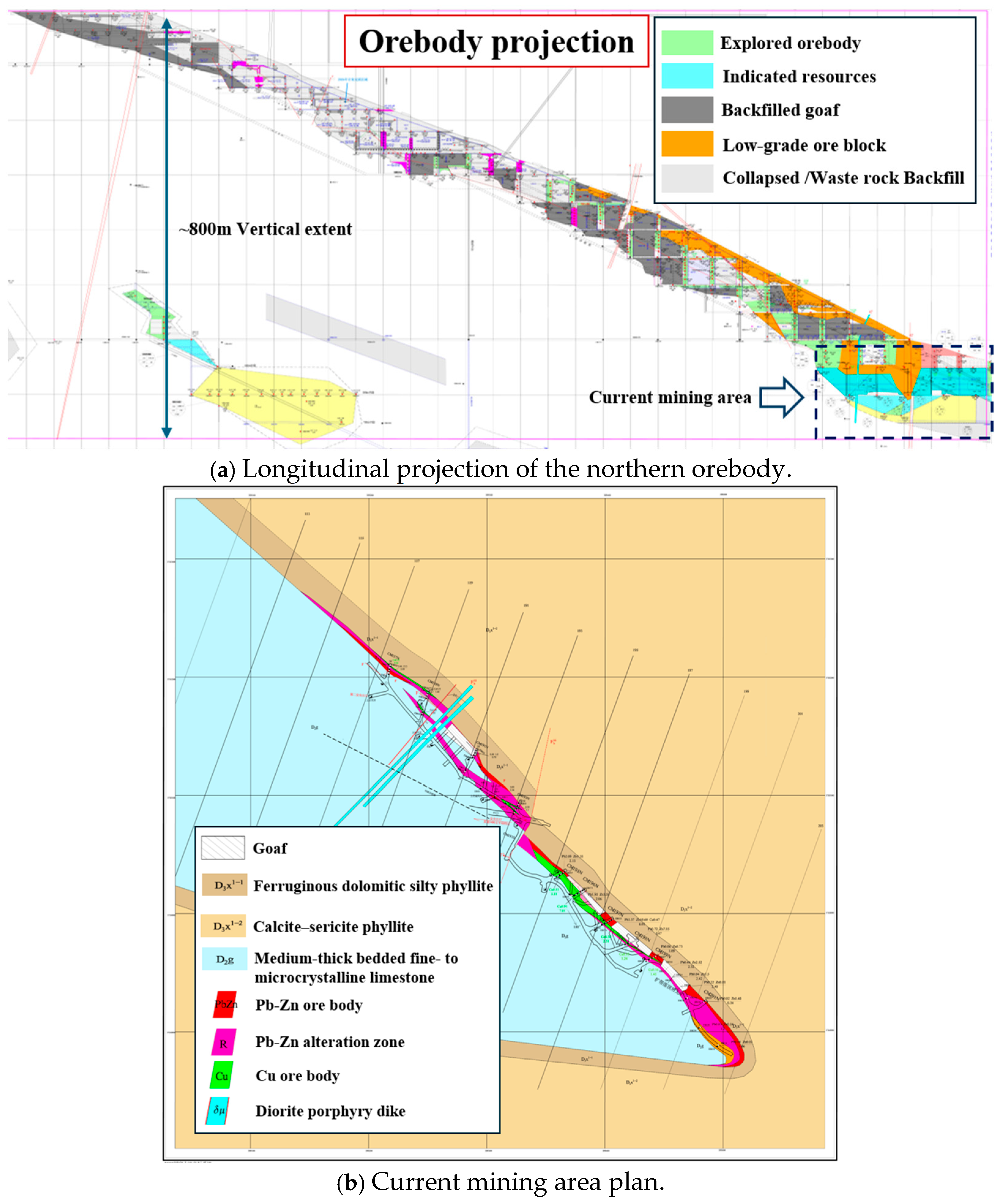
The Erlihe lead–zinc mining area is mainly divided into three orebodies: No. I, No. II, and No. III. The No. II-1 orebody is the main production OB of the Erlihe lead–zinc mine. Currently, mining operations are mainly concentrated in the north wing orebody, which is located at the 800 m level. The OB’s dip angle ranges from 60° to 84°, and the thickness of OB ranges from 0.85 m to 13.60 m. Figure 1 shows the OB details. Figure 1a presents the longitudinal projection of the northern orebody, and Figure 1b displays the current mining area plan.
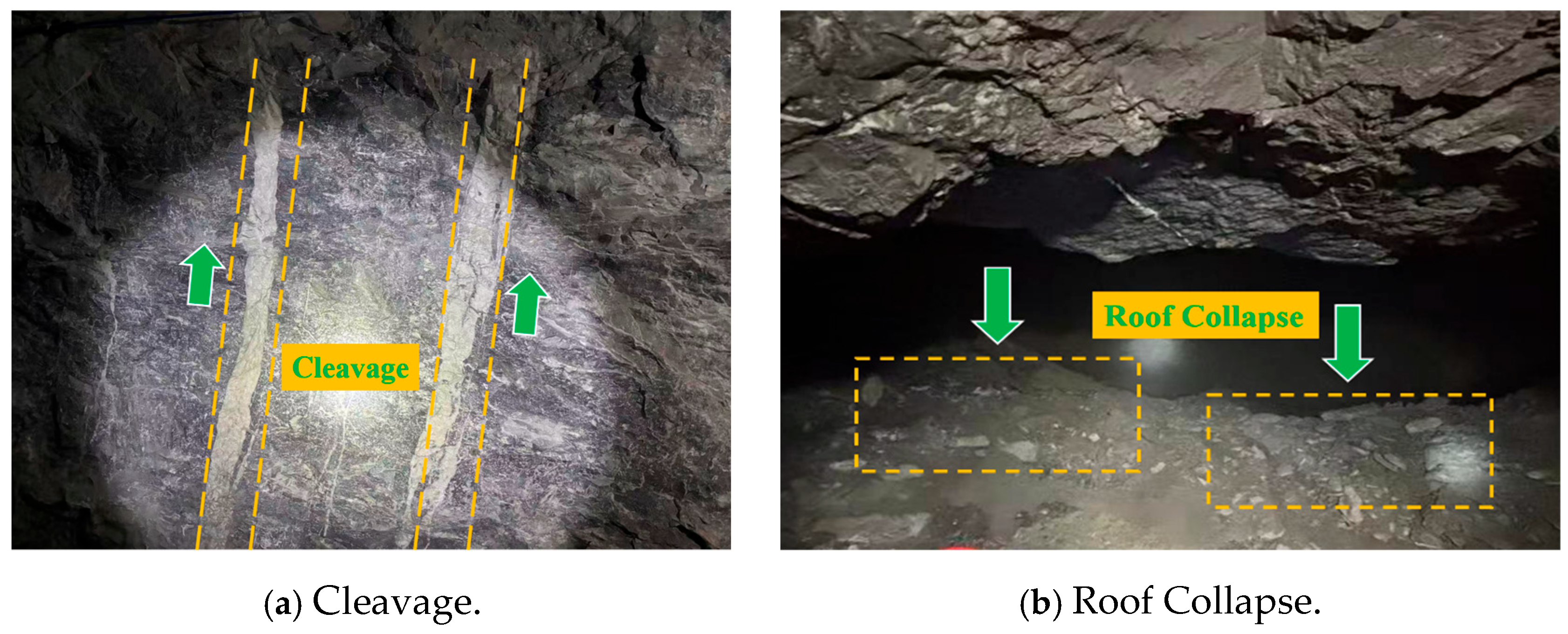
The hanging wall rockmass is mainly phyllite, based on exploration boreholes and field observations. The footwall is mostly limestone and a relatively stable surrounding rockmass. The rockmass in the mining area is generally dense and hard, and the bedding structure is not well-developed for the mining zones; however, the phyllite has an obviously developed cleavage structure, as shown in Figure 2a. When mining towards the deep levels (the north wing side), the orebody dip angle is relatively large, and the orebody thickness varies significantly. As the current stoping has reached 800 m, the phyllite is rich in flaky minerals such as sericite and chlorite. In a humid environment, water infiltration weakens the cohesion between mineral particles [27,28] and also reduces the shear strength of the cleavage planes, which significantly decreases the cohesion and internal friction angle of the rockmasses. Consequently, the compressive strength of the rockmass decreases. Furthermore, a large area of exposed phyllite roof is formed during orebody stoping. The stope back has poor structural integrity and is prone to collapse once a continuous fracture zone or block sliding occurs. Underground, some roof falls or even local roof collapses have been observed during stoping; see Figure 2b. If the roof falls or the back collapses, it will affect normal mining production and also pose a threat to the safety of personnel and equipment. Meanwhile, these FOG (fall of ground) or stope back collapses lead to waste rock inclusion and cause fluctuations in stope ore quality. Consequently, the dilution rate and loss rate are difficult to control effectively in daily production.
Existing mining methods mainly rely on the self-stability of the host rockmass to varying degrees or use delayed backfilling for compensation to the host rockmass. A common issue of the current mining methods is the long exposure time of the stope during extraction. These methods show insufficient adaptability to the conditions of the weak hanging wall; consequently, the current mining method fails to address certain concerns, such as long operation exposure times, rockmass instability, and increasing dilution rates. It is therefore important to address the stope roof stability problems while ensuring mining efficiency at the same time. Certain goals are clear, such as reducing the exposure time of weak stope back, controlling the hanging wall collapse, reducing the dilution rate, and improving the resource recovery level. These goals have become key issues that need to be addressed for the Erlihe lead–zinc mine, specifically for the extraction of the deep northwing OB.

3. Proposed Synergistic Mining Method

Due to the large variations in OB thickness and hanging wall strength, the current stoping mining method is not an ideal solution for the Erlihe mine, especially for the north wing No. II-1 OB. In this manner, a synergistic mining method is proposed to meet the requirements of OB and hanging wall conditions by considering multiple combinations of different stoping methods with backfilling.
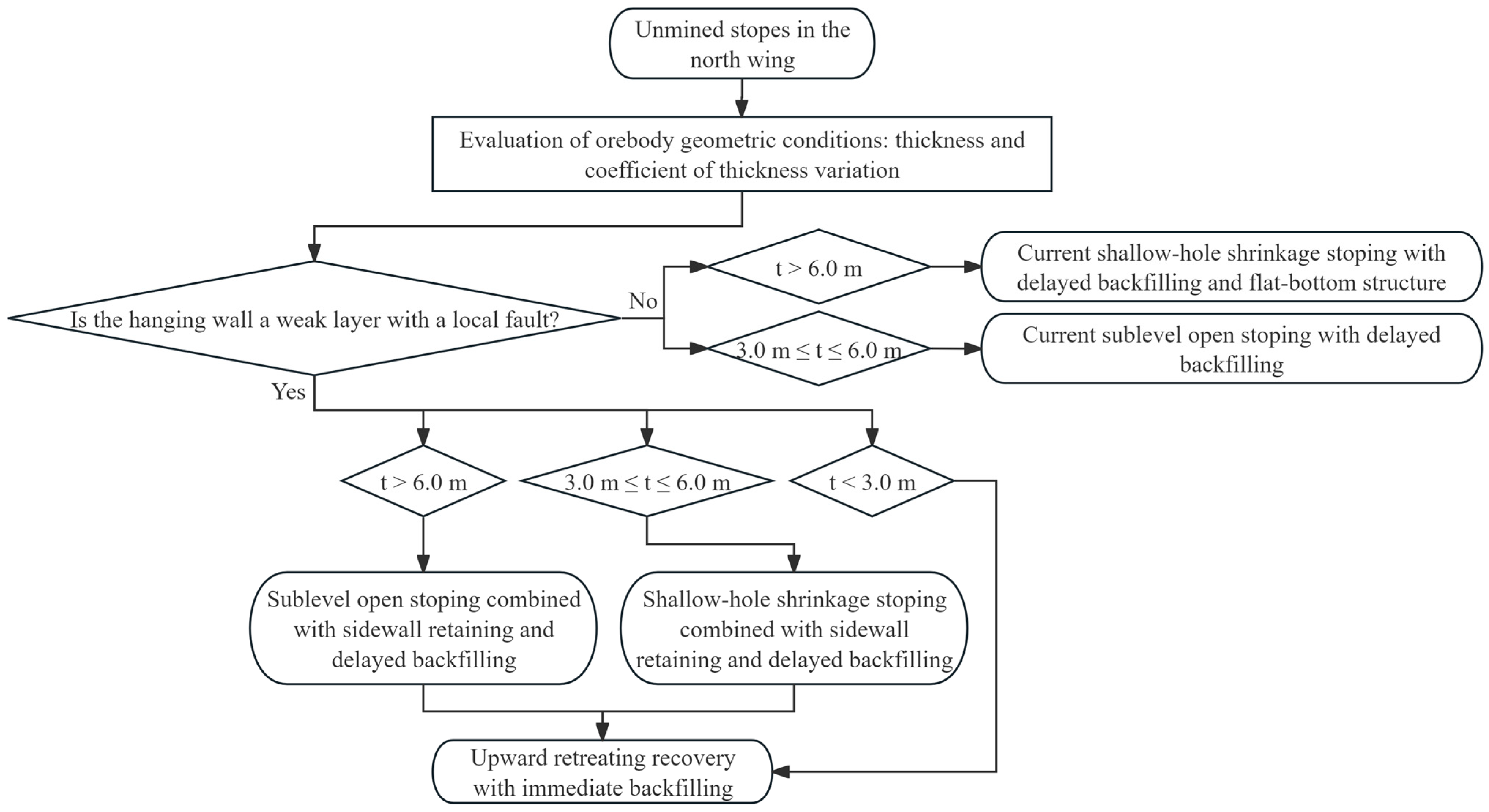
Figure 3 shows the design flowchart of the proposed synergistic mining method, which is designed to address the variations in OB and unstable stope back failure issues.
As shown in Figure 3, five mining methods are included in the synergistic mining considering different HW conditions and geometric situations of OB.
The novelty of this method does not lie in proposing the concept of a ‘retaining sidewall’ in isolation, but in systematically integrating the reserved retaining sidewall, sublevel open stoping, delayed backfilling, and the delayed recovery sequence for steeply inclined thin-to-medium-thick OBs under weak HW conditions, and in establishing a mining method selection framework based on OB thickness and HW stability (Figure 3), thereby forming an integrated design approach applicable to this specific type of engineering condition.
The workflow first takes OB thickness t as the initial criterion, using 3.0 m and 6.0 m as classification thresholds to make a preliminary division of mining risk under different thickness conditions. On this basis, the condition of the HW rockmass is further introduced as a decision factor. When HW conditions are favorable and the surrounding rock is relatively intact, the existing methods may be preferentially adopted to balance technical feasibility and economic efficiency; however, when the HW consists of weak phyllite, developed faults, or other unfavorable low-strength conditions, and is further subjected to a large exposure span or a long exposure duration, the concentration of tensile–shear stress and the probability of instability in the surrounding rock increase significantly, making stronger control measures necessary.
In this fashion, considering different high-risk pathways, control measures are strengthened with OB thickness classification: when t > 6.0 m, the sublevel open stoping method with reserved retaining sidewall and delayed backfilling is preferentially adopted; when 3.0 m ≤ t ≤ 6.0 m, under the premise of ensuring safety, sublevel open stoping is adjusted to a lower-cost shallow-hole shrinkage type method; when t < 3.0 m, the method is further shifted to one more suitable for narrow-vein conditions and with relatively lower cost. In other words, when the risk of HW instability is low, conventional open stoping or shrinkage methods may be adopted, whereas when the risk is high, schemes incorporating a reserved retaining sidewall or timely backfilling should be prioritized according to OB thickness in order to enhance stope safety.
Based on the actual engineering conditions of the north wing of Erlihe No. II-1 OB, it is believed that the combination of sidewall retaining and sublevel open stoping with delayed backfilling would be the primary mining method for the north wing mining zone. In this mining method, the medium-thick OB is divided into a protective sidewall retaining, stope room, and pillars. As mentioned, a protective wall retaining is reserved on the hanging wall side before mining, which forms a relatively stable isolation boundary for the stope unit. Subsequently, different open stoping methods are adopted according to the OB thickness constraints (Figure 3). Once the stope is fully mined out, a bearing structure should be formed in a timely manner through delayed backfilling. Afterwards, the rib pillar and the sidewall retaining pillar are extracted. In this mining sequence, the exposure time of the stope back is reduced and controlled in a proper way, which can limit the collapse of phyllite and reduce the ore dilution rate. In the following, details about the key mining stages are given in terms of development, cutting, and stope extractions.

3.1. Development and Cutting

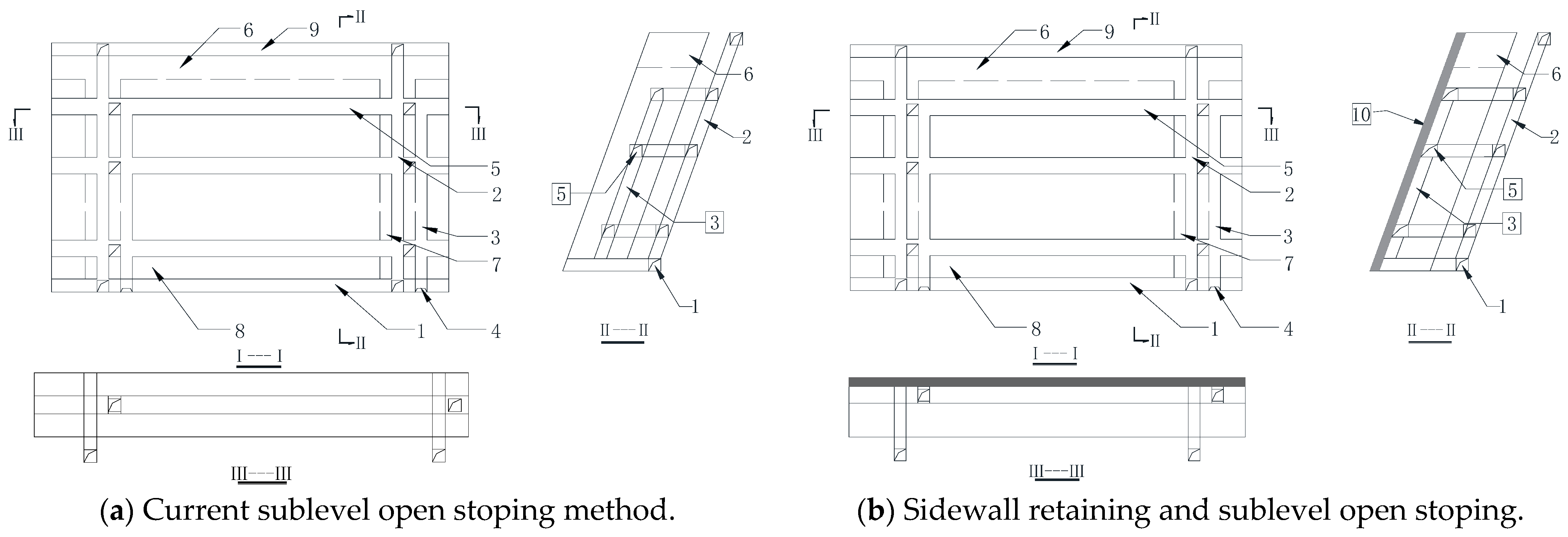
The development and cutting mainly include several engineering excavations, which are the haulage drift, manway raise, return airway, ore pass, and crosscut. Figure 4 shows the orthographic views of the two mining methods. Figure 4a gives the current sublevel open stoping with delayed cemented backfilling, and the proposed mining method using a sidewall retaining with sublevel open stoping is shown in Figure 4b.
The fundamental difference between these two mining methods is visible when comparing them, as in Figure 4a,b. In Figure 4b, an additional protective sidewall retaining structure is designed, as denoted by gray and labeled as number 10. In addition, specific workings are relocated; the ore pass (3) and the sublevel drilling drift (5) are advanced to the side adjacent to the protective sidewall retaining structure. In contrast, the ore pass and sublevel drilling drift in Figure 4a are located in the center of the orebody. This new design maximizes the use of existing mining excavations and saves the project cost effectively.
The stope layout was designed based on the existing mine development system to form an economical and efficient sublevel mining structure. As shown in Figure 4, the stope height is 42.2 m, with a strike length of 50.0 m and a width of 10.6 m, in order to avoid the formation of large-span open stopes. To ensure the overall stability of the stope, the thickness of both the crown pillar and sill pillar was designed as 6.0 m, and an 8.0 m wide inter-stope pillar was arranged between adjacent stopes.
The primary task of development and cutting is to construct a stope production system. The haulage drifts are preferentially arranged in the stable surrounding rockmass at the footwall side. The size of the main level haulage drift is 2.2 m × 2.6 m. Crosscuts are excavated from the haulage drift toward the orebody and reach the footwall boundary. The interval distance between crosscuts is determined by the stope length and ventilation conditions. The size of the crosscut is designed as 2.0 m × 2.0 m. Based on existing practices, a flat-bottom ore-drawing structure is adopted at the stope bottom.
Regarding the vertical system layout of the stope, each ore block is designed with a manway raise and an ore pass. The manway raise also serves as a ventilation drift and a route for backfill pipelines to form complete production cycle conditions for the stope. The ore pass (2.0 m × 2.0 m) uses gravity for the ore flowing and connects to the haulage system. The ore pass also serves as a development slot raise and a backfill raise. The ore pass is excavated in an overhand manner and penetrates the entire stope height, which provides a free face for stope blasting work. After the completion of the slot raise, fan-shaped blast holes are drilled for slot widening, and a cutting slot (3.0 to 4.0 m) is ultimately created. The formation of the cutting slot can provide a stable free face for the subsequent sublevel medium-long hole blasting.

3.2. Protective Wall Retaining Construction and Protection

As shown in Figure 4, a certain thickness of the OB is reserved as a protective wall retaining structure. It is located on the HW side of specific stopes along the orebody strike. During the stope design stage, the layout and thickness of the protective wall retaining is determined based on multiple factors such as the orebody thickness and the strength of the surrounding rockmass. The protective wall retaining is arranged near the contact zone between the hanging wall and the surrounding rockmass. It is designed continuously along the orebody strike, and the thickness is controlled at 1.0 to 2.0 m. This ensures the protective wall retaining has sufficient bearing capacity during the extraction stage. The profile of the protective wall retaining is marked in the stope design drawings and is precisely controlled through underground field surveying.
The sublevel drilling drift is used as the protective wall retaining construction drift. It provides working space for drilling control holes in the protective wall retaining. Meanwhile, it exposes the conditions of the protective wall retaining in advance. This achieves precise control over the protective wall boundary. The construction drift is generally arranged on the inner side of the protective wall. The shape of the drift is a right trapezoid with approximately 2.0 m (upper base) × 2.5 m (lower base) × 2.0 m (height). Necessary ground support is needed according to the stability condition of the surrounding rockmass. The support elements include rock bolts, wire mesh, or shotcrete. Subsequently, a row of protective wall control holes is arranged within the construction drift, which are aligned along the designed boundary of the protective wall retaining. This arrangement can form a clear blasting boundary during the construction and also reduces the propagation of blasting cracks toward the protective wall retaining side. The diameter of the control holes ranges from 64.0 to 76.0 mm, and the hole spacing ranges from 0.6 to 1.0 m. The hole depth is consistent with the sublevel height, and these holes are charged lightly to achieve a small influence of blast vibration on the structure, and to reach a good blasting boundary control.
During the stoping stage, a medium-long hole drilling system is set up in the sublevel drilling drift. The drilling direction is inclined toward the mined-out area or the footwall side to ensure the blasting energy is primarily released toward the mined-out area; in this way, it can reduce the dynamic disturbance to the protective wall retaining. Controlled blasting techniques are used during the orebody blasting process to ensure the integrity of the protective wall structure. Specifically, the explosive charge in the blast holes is reduced near the protective wall, and millisecond delay initiation is adopted in the blasting. In addition, a buffer zone of approximately 0.3 to 0.5 m is reserved between the protective wall and the blasting area. These measures can effectively reduce the impact of blasting disturbance on the protective wall. After blasting, the fragmented ore blocks are extracted through the stope bottom ore-drawing structure. During the ore-drawing process, impacts from large equipment on the protective wall should be strictly avoided. If necessary, rock bolts or shotcrete support can be applied to local areas of the protective wall to ensure the stability of the protective wall during the ore extraction stage.

3.3. Stoping Work

3.3.1. Room Extraction

Room extraction is the first extraction stage and primarily uses sublevel open stoping with delayed backfilling. The contour line of the protective wall side should be strictly controlled during the room extraction process to avoid overbreak and subsequent ore dilution. Medium-long blast holes are arranged in the sublevel drilling drift within the orebody. These holes are drilled upward in a fan-shaped pattern, and millisecond delay initiation technology is used for stope blasting. After blasting, scaling is conducted to remove loose rocks in a timely manner. Reinforcement support is applied to the loose zones of the protective wall. The ore is drawn through the flat-bottom ore-drawing structure and transported to the ore pass. Then, the blasted ore is transported to the haulage system. After cleaning the stope bottom, the mined-out area is inspected for the following backfilling.

3.3.2. Backfilling

The construction of fill barricades, drainage inspection, and installation of backfill pipelines are constructed before the backfilling work. The backfilling sequence follows a specific principle of ‘first the protective wall side, then the central part, and finally the topping off’. This practice allows the protective wall boundary to preferentially form a load-bearing structure. Eventually, the backfill body mass forms a continuous load-bearing structure and reaches the designed strength. Once the backfilled body reaches the required strength, the residual pillars can be recovered.

3.3.3. Pillar Recovery

Pillar recovery is the second mining stage. In this method system, the pillar is not a permanent load-bearing structure. Instead, it is a temporary support body, and pillar extraction must meet strict engineering criteria. First, the adjacent mined-out stopes must be completely filled with cemented backfill, and the backfill mass must form a continuous load-bearing structure in space. Second, the backfill strength must reach the designed extraction strength threshold to ensure that the backfill body can replace the original pillar to bear the surrounding rockmass load. Third, the host rockmass monitoring must confirm that the stope deformation has entered a stable stage. The displacement rate of the hanging wall must significantly decrease. There must be no continuously propagating cracks or shear bands within the host rockmass. The pillar recovery stage can only begin when all the above conditions are met simultaneously. The pillar recovery sequence follows the principle of advancing from low risk to high risk. Usually, the pillar should be recovered in the order of rib pillar, protective wall retaining, sill pillar, and finally the crown pillar. For sure, backfilling must be carried out immediately after recovering a part of the pillar. It is worth mentioning that the timely backfilling of mass to spatially replace the pillar in bearing the host rockmass load, and a smooth stress transfer, could be achieved.

3.3.4. Recovery of Protective Wall Retaining

As emphasized that the protective wall retaining functions to stabilize the hanging wall. Before recovery, the stability of the stope back must be inspected, and on-site monitoring must confirm that the hanging wall surrounding rock is in a stable state. Regarding the extraction method, the protective ore wall retaining should be extracted in strips to advance gradually. This prevents stress re-concentration in the surrounding rock caused by a single and large-scale extraction. The extraction should proceed sequentially along the orebody strike. This creates an alternating load-bearing structure of ‘backfill mass—protective ore wall—backfill mass’ inside the stope. As a result, the stress of the host rockmass can be gradually transferred and could effectively reduce the risk of stope back instability.

4. Numerical Modeling of the Current and Proposed Mining Method

As mentioned, the sidewall retaining and sublevel open stoping with delayed backfilling would be the primary mining method for the north wing mining zone. To demonstrate the advantages of the proposed mining method, a numerical model is conducted in Section 4 to study the benefits of the proposed mining method compared with the current mining method. MIDAS GTS is a geotechnical numerical analysis software based on the FEM (finite element method) [29]. The FEM shows good adaptability in handling complex geometric structures and multi-stage excavation processes, and it is, therefore, appropriate to use MIDAS GTS (2026 version) in conducting 3D numerical models in this study.
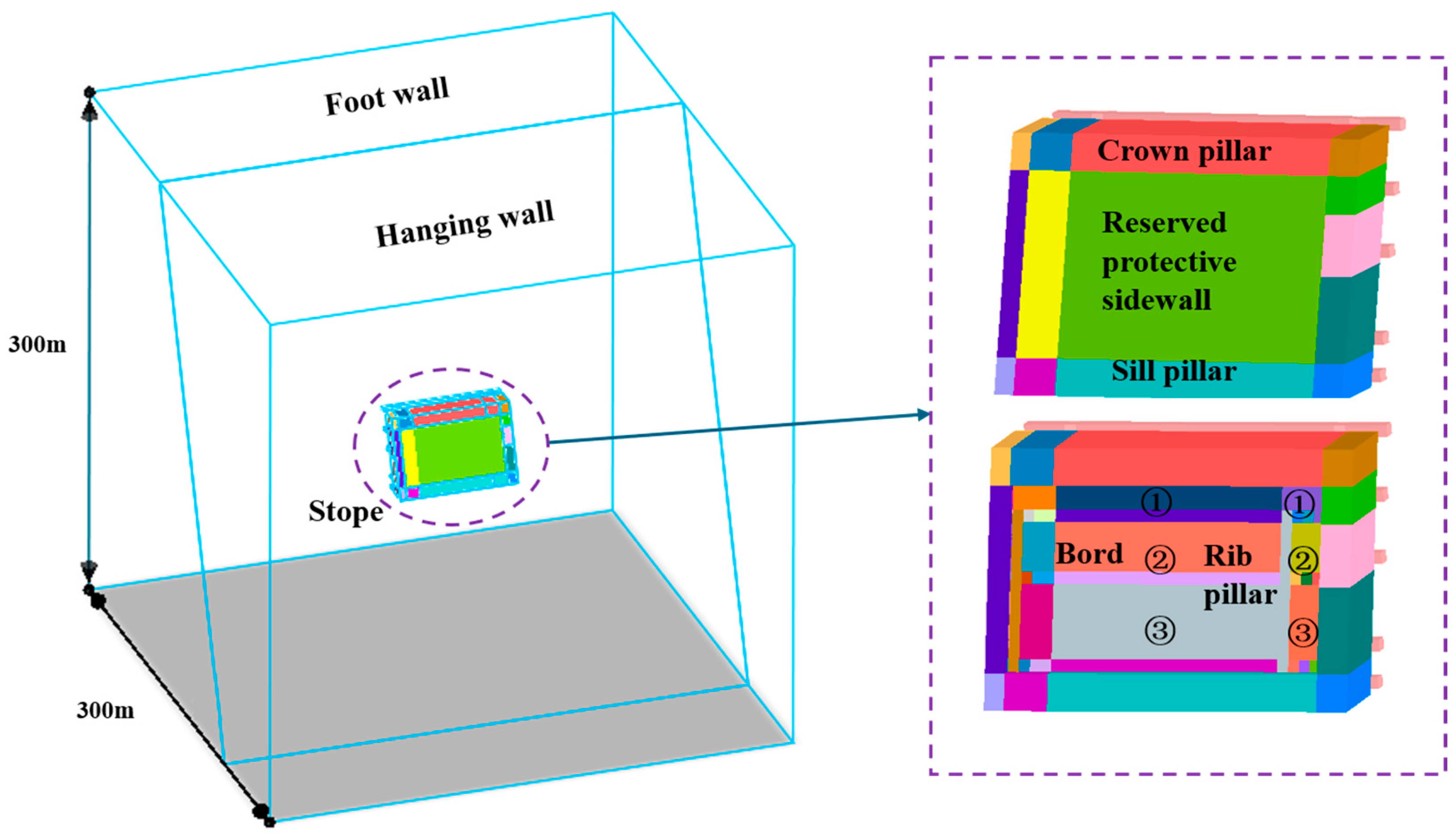
Figure 4 shows the stope layouts of the current and proposed mining methods. The current mining method is a sublevel open stoping with delayed backfilling (Current method: Method A). The new proposed mining method is sidewall retaining and sublevel open stoping with delayed backfilling (New proposed method: Method B). In addition, the location of the sublevel drilling drift in Method B differs from that in Method A, as shown in Figure 4 and the right inserts of Figure 5. The element size is 0.5 m for the OB and drifts, and the element size ranges from 1.0 to 6.0 m for the host rockmass. The model contains 343,615 elements in total.

4.1. Model Description and Boundary Conditions

According to the actual engineering conditions of the mining stope, the simulated stope is arranged along the orebody strike. The dip angle is 75°, and the strike length is 67.0 m. The cross-section of the sublevel drilling drift is set to a right trapezoid shape (upper/lower base is 2.0/2.5 m) to ease the model construction. The protective sidewall retaining is set to 1.5 m. Other drift sizes can be found in Section 3.
In this model, displacement constraints are adopted for the boundary conditions. Horizontal constraints are applied to the lateral boundaries in the X and Y directions. Vertical constraints are applied to the bottom boundary. The top boundary is set as a free surface without any constraints. Considering the stope mining depth is about 800.0 m, an overlying rockmass stress of 15.0 MPa is applied to the top surface.

4.2. Constitutive Model and Model Parameters

The influence of geological factors such as faults and structural fracture zones within the OB has been taken into account through the reduction in rockmass mechanical parameters. In this way, the OB, surrounding rock, and backfill in the model are then simplify assumed to be homogeneous, continuous, isotropic media, and numerical analysis is carried out using the Mohr–Coulomb constitutive model. All the parameters adopted in the model are derived from available resources related to this mine. The Mohr–Coulomb constitutive model has been widely used in rockmass analysis [25,30]; the Mohr–Coulomb model is adopted in this study as a simplified model for engineering-level comparative research. Its results are mainly used to evaluate the relative changes in stress–deformation response under different mining methods, rather than to precisely describe all microscopic failure mechanisms of the hanging wall surrounding rock. Table 1 gives the physical and mechanical parameters of the rockmass and backfilling body that are used in this model; all the input parameters are obtained from the geological reports and related project data from Erlihe zinc–lead mine, i.e., [31]. These process parameters serve only as supporting measures for the engineering implementation of the new method, and their specific influence mechanisms and sensitivity patterns with respect to stability still require more targeted future research.

4.3. Simulation Schemes

Since the new proposed mining method involves a multi-stage construction process, it is, therefore, necessary to simulate the stress redistribution and deformation response of the host rockmass at different mining stages. Dynamic construction stages are set in the numerical model. To summarize, the four main construction stages are detailed in Table 2. In the numerical simulation, the excavation steps are simulated sequentially according to Table 2. The four main stages include stope extraction, rib pillar extraction, sill pillar extraction, and crown pillar extraction. The simulation of the new proposed method also includes a protective wall retaining recovery stage. The mined-out area is backfilled after each extraction.

5. Analysis and Discussion of Modeling Results

In this Section, key modeling results are selected and compared between the current Method A and the new proposed Method B to verify the rationality of the new proposed method. The stress and displacement distributions of the crown pillar are compared and analyzed at the same extraction stage. Moreover, the displacement distribution and plastic zone evolution are also evaluated for the host rockmass.

5.1. Crown Pillar Stability

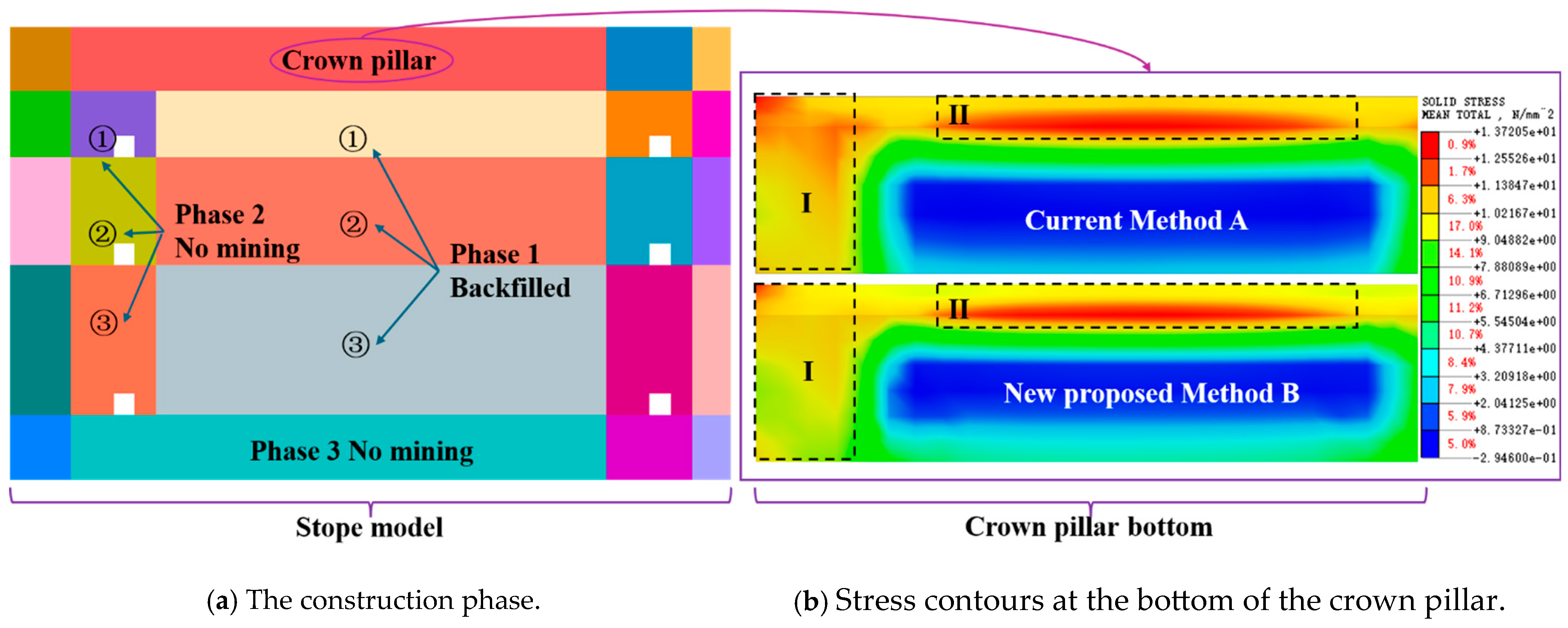
Figure 6 shows the distribution characteristics of the total stress at the bottom of the crown pillar. The figure presents the results after completing Phase 1 for both mining methods. Figure 6a illustrates the construction phase corresponding to the stress contour on the right. The stress distribution results indicate that both mining methods generate a pronounced stress concentration zone at the bottom of the crown pillar. The red and orange regions correspond to the areas with the highest stress concentration, which are mainly distributed along the stope roof and the side boundaries. However, the intensity and spatial distribution characteristics of these high-stress zones differ significantly between the two methods.
As illustrated in Figure 6b, under the current mining Method A, the peak stress reaches approximately 13.72 MPa. The high-stress zones form a relatively continuous stress band along the bottom of the crown pillar. This distribution pattern suggests that, after ore extraction, the load of the overlying rockmass is rapidly transferred toward the bottom and both lateral ends of the crown pillar, thereby inducing localized stress concentration in these regions.
In contrast, under the new proposed Method B, the peak stress at the bottom of the crown pillar decreases to 12.86 MPa. Compared with the 13.72 MPa observed in Method A, the peak stress is reduced by approximately 0.86 MPa, corresponding to a reduction of about 6.27%.
As can be seen from Figure 6b, in Region I, the high-stress zone dominated by red is more pronounced in Method A, corresponding mainly to a stress range of 11.38–13.72 Mpa, whereas in Method B, the previously dark-red-dominated high-stress zone in Region I is reduced and is replaced to a greater extent by yellow and orange stress levels of 9.05–11.38 MPa. In Region II, the width of the high-stress zone is also clearly greater in Method A than in Method B. This indicates that, although the difference in peak stress between the two methods is not very large in itself, the stress improvement provided by the new method is reflected not only in the reduction in a single peak value, but also in the overall contraction of the stress concentration band and the weakening of the locally dominant high-stress area.
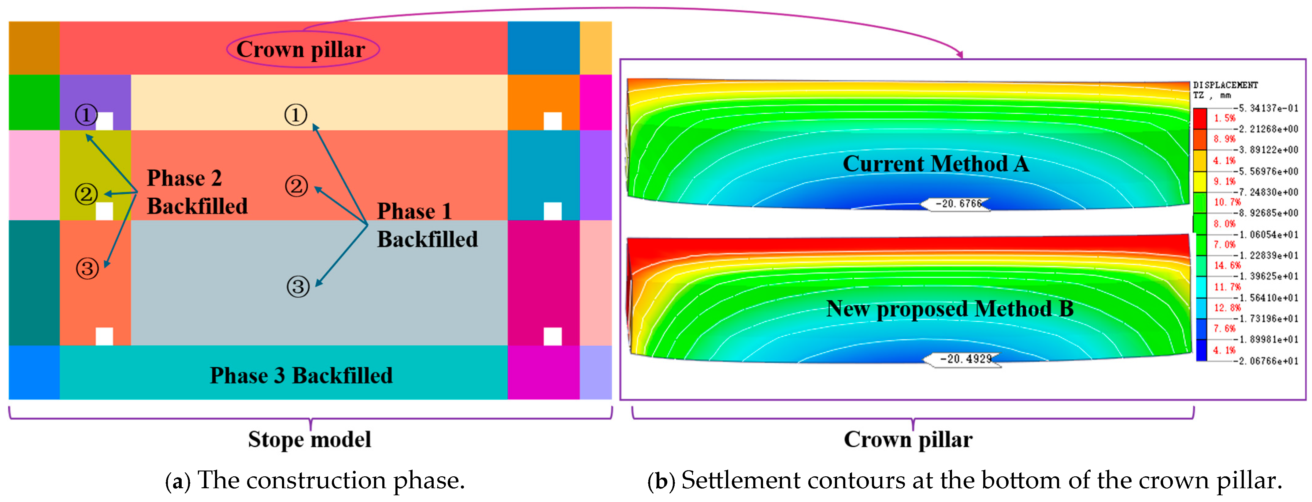
Figure 7 shows the settlement of the crown pillar. The figure presents the calculated results for both mining methods after the completion of Phases 1, 2, and 3 mining and backfilling, respectively. Figure 7a illustrates the excavation stage corresponding to the displacement contour shown on the right.
As shown in Figure 7b, under both mining methods, the settlement of the crown pillar generally increases from both ends toward the central region, with the maximum subsidence mainly occurring in the lower–central part of the crown pillar. However, clear differences can be observed in the spatial distribution of the displacement field between the two methods. Under the Current Method A, the high-displacement zones exhibit darker colors and a wider spatial extent, indicating a more pronounced settlement concentration at the bottom of the crown pillar.
Meanwhile, the displacement contours become noticeably denser near the stope ends, reflecting a stronger deformation gradient in these areas. In contrast, under the new proposed Method B, the extent of the high-displacement zone is significantly reduced, the color transition is more uniform, and the displacement contours appear more continuous and evenly distributed. This indicates a more coordinated deformation within the crown pillar.
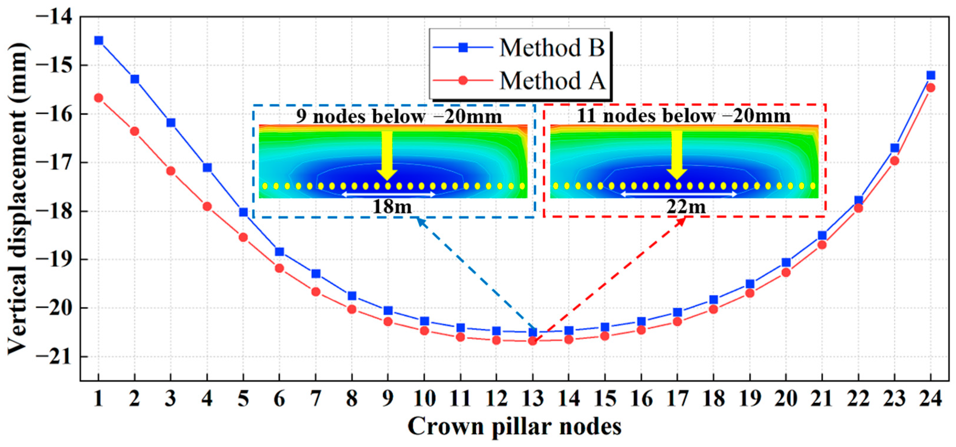
Figure 8 shows the settlement results of the 24 nodes arranged along the stope strike. Under both mining methods, the crown pillar settlement exhibits a typical U-shaped distribution, with the maximum subsidence occurring at node 13 near the center of the crown pillar. Under the Current Method A, the maximum subsidence reaches 20.68 mm, whereas under the new proposed Method B, it is 20.50 mm, representing a reduction of 0.18 mm (peak relative error approximately 0.89%). Meanwhile, the mean subsidence under Method A is 18.91 mm, which is higher than 18.57 mm under Method B.
The 24 nodes are uniformly distributed along the strike direction at the bottom of the crown pillar, with a spacing of 2.0 m. These nodes are used to characterize the spatial distribution of the maximum settlement curve. The positions are marked as yellow dots in Figure 8. When −20 mm is adopted as the line for the main settlement zone, the main settlement zone of Method A covers 11 nodes, corresponding to a length of 22.0 m, whereas Method B covers 9 nodes, corresponding to a length of about 18.0 m. Compared with Method A, the influence length of the main settlement zone is 4.0 m shorter for Method B, corresponding to a reduction of 18.2%. This result indicates that the advantage of Method B lies not only in reducing the peak settlement, but also in reducing the extent of the main settlement influence zone.
In addition, nodes 1–4 at the stope end are located directly above the inter-pillar region, reflecting the influence of the current mining phase on crown pillar settlement. The results show that the average subsidence in this region under Method A is approximately 16.77 mm, whereas it decreases to 15.76 mm under Method B, corresponding to a reduction of 1.01 mm (peak relative error about 6.05%). Overall, the new proposed Method B can effectively mitigate deformation concentration at the crown pillar ends and reduce the extent of the subsidence influence zone, thereby improving crown pillar stability.

5.2. Hanging Wall Stability

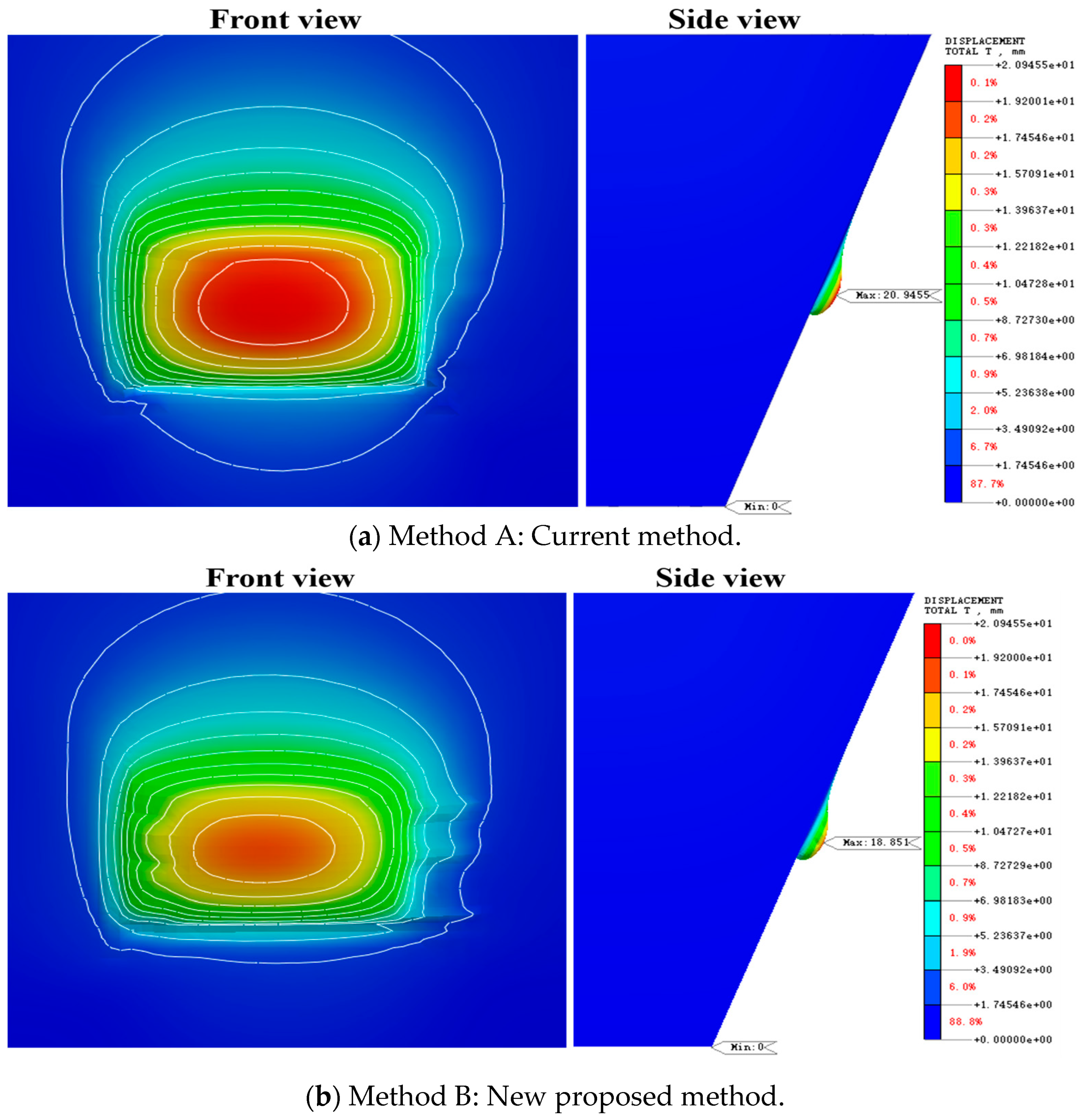
Figure 9 presents the front and side views of the displacement field in the HW surrounding rockmass after pillar recovery and backfilling in Stages 1 and 2. Under both mining methods, a distinct displacement concentration zone develops in the hanging wall rock above the stope, which gradually attenuates outward in an approximately elliptical pattern.
In the front view, the high-displacement zone under Method A shows darker colors and a larger spatial extent, with the red and orange regions extending further toward the roof and the surrounding rock on both sides. In contrast, under the new proposed Method B, the high-displacement zone is significantly reduced, and the colors become lighter, indicating a more uniform attenuation of displacement toward the periphery. In the side view, the high-displacement zone under Method A extends further into the hanging wall surrounding rock, whereas under Method B, the displacement is mainly concentrated in a limited area directly above the stope.
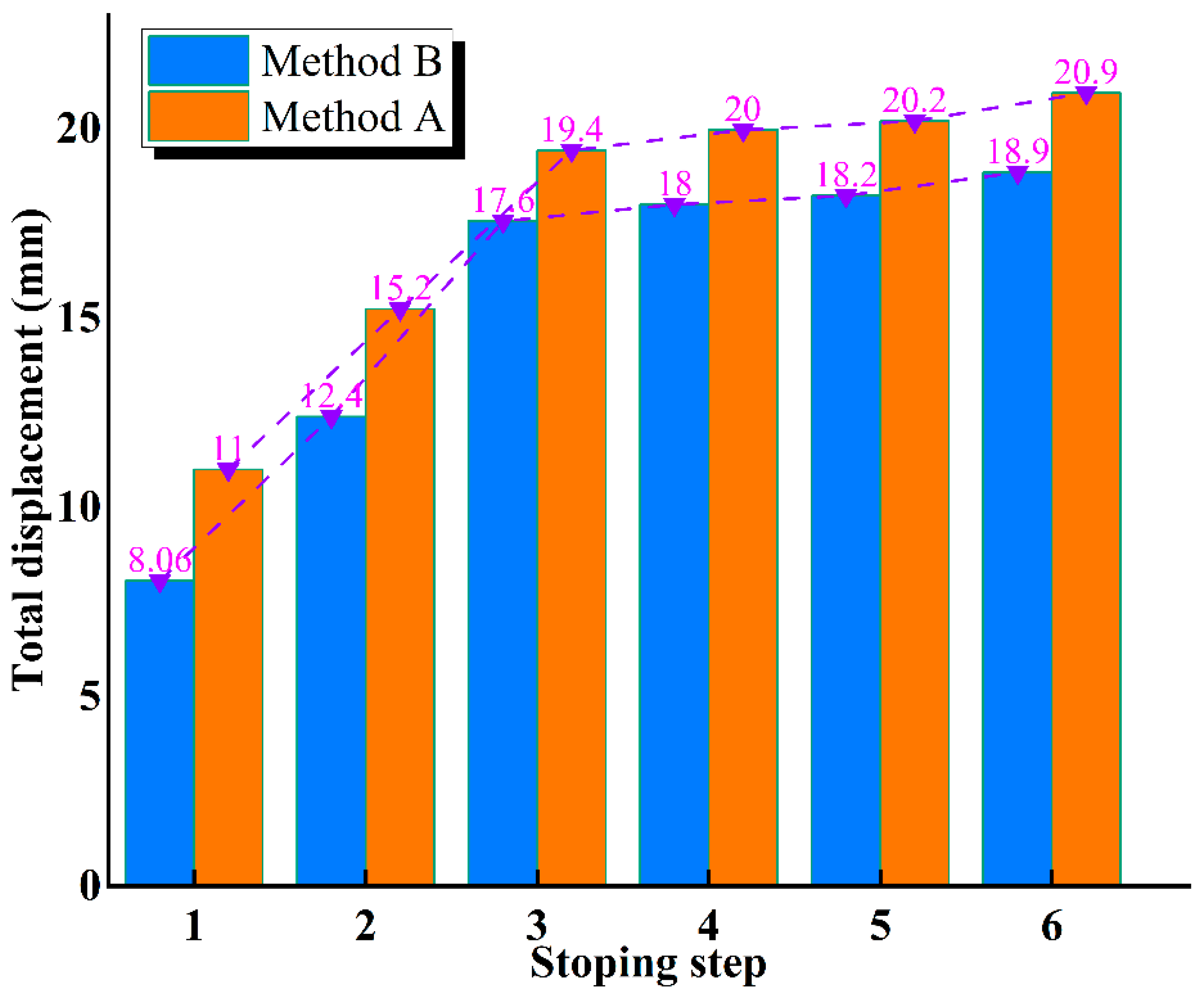
Figure 10 illustrates the evolution of the maximum displacement of the HW surrounding rock under the two mining methods at different extraction stages. Steps 1–3 correspond to the stoping and backfilling of the segmented stopes (Phase 1), whereas steps 4–6 represent the recovery and backfilling of the three inter-pillars (Phase 2). Overall, the maximum displacement of the HW gradually increases with the advance of the mining steps under both methods, indicating the progressive accumulation of mining-induced disturbance and the continuous development of deformation. However, clear differences exist between the two methods in terms of displacement growth magnitude and stage response characteristics.
During Steps 1–3, the maximum displacement under Method B is 8.08 mm, 12.4 mm, and 17.6 mm, whereas the corresponding values under Method A reach 11.0 mm, 15.2 mm, and 19.4 mm, respectively. Compared with Method A, Method B reduces the displacement by 26.5%, 18.4%, and 9.3% at the three stages, indicating that the new method can mitigate the influence of mining-induced unloading on the HW. In terms of displacement growth rate, the average increase under Method B during Steps 1–3 is approximately 4.76 mm/step, compared with 4.20 mm/step under Method A. This suggests that although both methods induce noticeable deformation responses in the HW during the early mining stages, the overall displacement level under Method B remains consistently lower.
During Steps 4–6, the HW displacement continues to increase under both methods, but the growth trends become distinctly different. The maximum displacement under Method B increases from 17.6 mm to 18.9 mm, corresponding to a growth rate of approximately 0.65 mm/step, whereas under Method A, it increases from 19.4 mm to 20.9 mm, with a growth rate of 0.75 mm/step. Compared with Phase 1, the displacement growth rates of both methods decrease significantly, indicating that the backfill gradually participates in load bearing and partially restrains the development of HW deformation. It is, however, Method A that still exhibits a larger displacement increment after inter-pillar recovery, reflecting a stronger mining-induced disturbance.
Further evaluation from the perspective of deformation reduction rate shows that, taking Method A as the reference, Method B reduces the displacement by 26.5%, 18.4%, 9.3%, 10.0%, 9.9%, and 9.6% at the six mining stages. Overall, the new method achieves an average displacement reduction of approximately 14% throughout the mining process. These results demonstrate that the new proposed Method B can continuously suppress the development of HW deformation at different mining stages, reduce the intensity of mining-induced disturbance, and effectively control the growth of HW displacement.
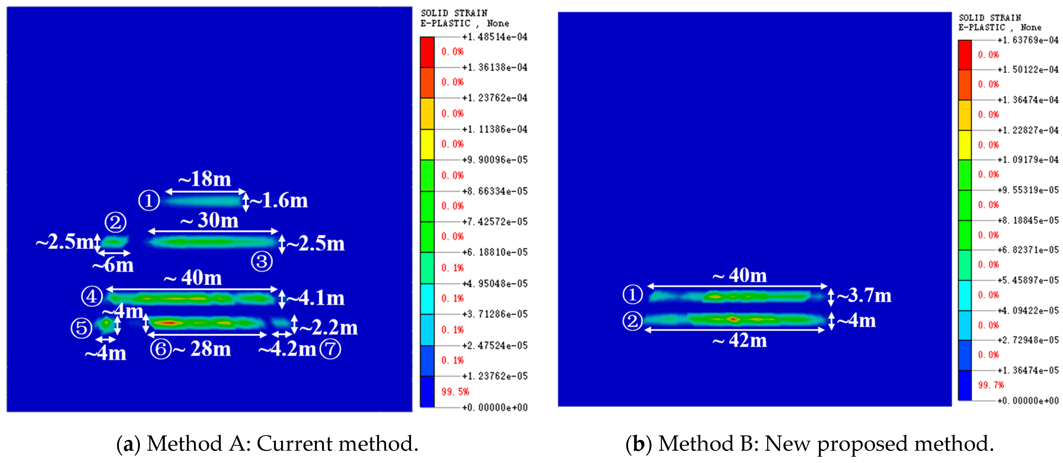
Figure 11 shows the distribution of the plastic zone in the HW surrounding rockmass for both mining methods. This represents the condition after the completion of all extraction stages. Under Method B, the overall scale of the plastic zone in the surrounding rockmass is relatively small and only occurs in limited areas. Most areas of the surrounding rockmass remain in an elastic state. By contrast, the extent of the plastic zone under the current Method A is somewhat larger, and the plastic zone also exhibits a certain degree of extension along the stope direction.
Based on the geometric extent of the plastic zones, the length, width, and area of each independent plastic zone are summarized in Table 3. From Table 3, the results show that the plastic zones under Method A exhibit a relatively obvious multi-region dispersed distribution pattern, forming seven independent plastic zones with a total area of approximately 420 m2. In contrast, the number of plastic zones under Method B is reduced largely, with only two relatively concentrated zones and a total area of about 316 m2, representing a decrease of approximately 24.8% compared with Method A.
It is noteworthy that under Method B, the plastic zone in the surrounding rockmass is not formed during the initial extraction stage. It only begins to occur after extracting the protective sidewall retaining, which indicates that the reserved protective sidewall retaining plays a bearing supporting role for the surrounding rockmass structure during the early extraction stage. The protective sidewall retaining can bear a portion of the overlying rockmass load, which hence weakens the stress concentration effect caused by stope excavation. Consequently, the surrounding rockmass maintains an elastic stress state for a longer period, and this may delay the development of plastic failure. The protective sidewall retaining is extracted in the later stage. At this time, the stress in the surrounding rockmass is gradually released and redistributed, and only then do local areas begin to enter the plastic state. The characteristic of the delayed development of the plastic zone is of great significance in engineering practice. The protective sidewall retains and effectively stabilizes the structure of the stope host rockmass during the early extraction stage. It reduces the possibility of the roof and sidewalls entering the plastic state prematurely. Consequently, it lowers the risk of surrounding rock instability and ore-waste mixing, which is beneficial for controlling the mining dilution rate.

6. Conclusions

In this study, a synergistic mining method combining sidewall retaining and sublevel open stoping with delayed backfilling was proposed for the steeply dipping thin-to-medium-thick orebody in Erlihe mine, and a comparative analysis was conducted through 3D numerical simulation. The improvements in stress, deformation, and plastic zone response should be understood as integrative effects under the existing engineering parameter system, and were used to evaluate the overall engineering performance of the proposed mining method rather than the independent contribution of each individual factor. The main conclusions are as follows:
(1) A design flow chart of the proposed method is given to consider different conditions of orebody thickness and local rockmass conditions. In the proposed synergistic mining method, five mining methods are included to ensure the stability of the stope back and cost-effectiveness. Certain key designs of the mining method are given, and details about the key mining stages are also summarized in detail for the development, cutting, and stope extractions.
(2) 3D numerical modeling is conducted to show the benefits of the proposed mining method compared with the current mining method. The new proposed method improves the stress and deformation distribution at the bottom of the crown pillar. Under Phase 1, the peak stress at the crown pillar base for proposed Method B is 12.86 MPa, representing a 6.27% reduction compared with 13.72 MPa under current Method A, and the spatial extent of the high-stress zone is noticeably reduced. The crown pillar subsidence under both methods shows a typical U-shaped distribution, but the maximum subsidence under new proposed Method B decreases to a certain extent. Meanwhile, the width of the main subsidence zone decreases from 11 nodes to 9 nodes, and the subsidence of the end region (nodes 1–4) decreases by approximately 6.05%. These results indicate that the reserved protective sidewall retaining optimizes the load transfer path of the overlying strata and reduces stress and deformation concentration in the crown pillar.
(3) The proposed Method B exhibits smaller displacement responses of the HW rockmass from modeling work. During the stope extraction stage, the maximum displacement decreases by 9.3–26.5%, while during the inter-pillar recovery stage, the reduction ranges from 9.6% to 10.0%, with an overall average reduction of approximately 14%. This demonstrates that the proposed Method B can reduce mining-induced disturbance and could control the development of surrounding rockmass deformation. For the new proposed method, the plastic zone in the hanging wall surrounding rock is smaller than that under the current method, and plastic development occurs later. This indicates that the reserved protective wall provides effective load isolation and structural support during the early mining stages, thereby delaying the onset of plastic failure and reducing ore dilution.
It should be mentioned that the conclusions of this study are drawn based on a specific engineering background and the corresponding numerical model configuration. The applicability and stability of the proposed method under different geological conditions and mining parameters still require further investigation, which will be a key focus of future work.

Author Contributions

Conceptualization, J.J. and X.W.; methodology, J.J. and M.K.; software, M.K. and L.Z.; validation, M.K. and X.W.; formal analysis, J.J. and X.W.; investigation, J.J. and X.W.; resources, J.J. and X.W.; data curation, J.J. and X.W.; writing—original draft preparation, J.J.; writing—review and editing, J.J., F.W. and X.W.; visualization, Z.L.; supervision, Z.L. and X.W.; project administration, J.J. and X.W.; funding acquisition, X.W. All authors have read and agreed to the published version of the manuscript.

Funding

This research was funded by the Science and Technology Program of Liaoning Province, grant numbers 2025JH2/101330167 and 2023JH1/10400004.

Institutional Review Board Statement

Not applicable.

Informed Consent Statement

Not applicable.

Data Availability Statement

The dataset compiled and used in this study is available from the corresponding author upon reasonable request.

Acknowledgments

The authors wish to thank Baoji Northwest Nonferrous Erlihe Mining Co. Ltd. for providing site-specific engineering data and field support.

Conflicts of Interest

Authors Jiayou Jing and Linhai Zhao were employed by the company Baoji Northwest Nonferrous Erlihe Mining Co., Ltd. The remaining authors declare that the research was conducted in the absence of any commercial or financial relationships that could be construed as a potential conflict of interest.

Abbreviations

The following abbreviations are used in this manuscript:
OBOre Body
HWHanging Wall
FWFoot Wall
FEMFinite Element Method

References

  1. Huang, S.; Zhou, J. Refined Approaches for Open Stope Stability Analysis in Mining Environments: Hybrid SVM Model with Multi-optimization Strategies and GP Technique. Rock Mech. Rock Eng. 2024, 57, 9781–9804. [Google Scholar] [CrossRef]
  2. Guo, Q.; Yu, H.; Dan, Z.; Li, S. Mining method optimization of gently inclined and soft broken complex ore body based on ahp and topsis: Taking miao-ling gold mine of china as an example. Sustainability 2021, 13, 12503. [Google Scholar] [CrossRef]
  3. Li, S.; Yu, L.; Dan, Z.; Yin, T.; Chen, J. The recent progress China has made in mining method transformation, part I: Shrinkage method transformed into backfilling method. Appl. Sci. 2024, 14, 10033. [Google Scholar] [CrossRef]
  4. Zhang, Y.; Hao, C.; Dong, L.; Pei, Z.; Fan, F.; Bascompta, M. Identification of regionalized multiscale microseismic characteristics and rock failure mechanisms under deep mining conditions. Int. J. Min. Sci. Technol. 2025, 35, 1357–1378. [Google Scholar] [CrossRef]
  5. Feng, F.; Li, D.; Li, X.; Guo, Z.; Wang, S.; Chen, Y. Novel underhand cut-and-fill stoping method and mechanical analysis of overlying backfill. Int. J. Geomech. 2017, 17, 04017004. [Google Scholar] [CrossRef]
  6. Du, H.; Li, X.; Huang, X.; Yang, Y.; Duan, S.; Su, T.; Yuan, X. Optimization of stope structural parameters for steeply dipping thick ore bodies: Based on the simulated annealing algorithm. Appl. Sci. 2024, 14, 11597. [Google Scholar] [CrossRef]
  7. Li, G.; Wan, Y.; Guo, J.; Ma, F.; Zhao, H.; Li, Z. A case study on ground subsidence and backfill deformation induced by multi-stage filling mining in a steeply inclined ore body. Remote Sens. 2022, 14, 4555. [Google Scholar] [CrossRef]
  8. Huo, X.; Shi, X.; Qiu, X.; Zhou, J.; Gou, Y.; Yu, Z.; Ke, W. Rock damage control for large-diameter-hole lateral blasting excavation based on charge structure optimization. Tunn. Undergr. Space Technol. 2020, 106, 103569. [Google Scholar] [CrossRef]
  9. Wang, R.; Zeng, F.; Li, L. Stability analyses of side-exposed backfill considering mine depth and extraction of adjacent stope. Int. J. Rock Mech. Min. Sci. 2021, 142, 104735. [Google Scholar] [CrossRef]
  10. Li, Y.; Mei, D.; Hu, X.; Luo, B. Study on the Influence of Two-Step Filling Mechanic Characteristics on the Stability of Single-Side Exposed Cemented Backfill. Symmetry 2025, 17, 126. [Google Scholar] [CrossRef]
  11. Lin, Y.; Zhou, R.; Zhou, K.; Li, J.; Yang, C.; Que, C.; Wu, F.; Xiao, Y. Simulation Study on Optimization of Structural Parameters of Stope Based on Ground Pressure Control. Appl. Sci. 2025, 15, 9998. [Google Scholar] [CrossRef]
  12. Saroglou, C. The Challenge of Rock Mass Classification of Anisotropic Rockmasses. Rock Mech. Rock Eng. 2025, 58, 11195–11215. [Google Scholar] [CrossRef]
  13. Fan, C.; Li, L.; Liu, G.; Yang, X.; Song, W.; Guo, L.; Wang, R. Numerical analysis of the stability and minimum required strength of sill mats considering creep behavior of rock mass. Int. J. Miner. Metall. Mater. 2025, 32, 1471–1482. [Google Scholar] [CrossRef]
  14. Wang, R.; Zhu, Y.; Liu, L.; Zhu, M.; Yan, B.; Cui, H. Time-dependent ground stability of inclined backfilled stope characterized by creep behavior. Int. J. Miner. Metall. Mater. 2026, 33, 479–491. [Google Scholar] [CrossRef]
  15. Guo, Y.; Miao, Y. Study on stope stability in continuous mining of long-dip, thin orebody by room–pillar method. Sustainability 2022, 14, 9601. [Google Scholar] [CrossRef]
  16. Sun, G.; Jin, A.; Lu, T.; Yang, J.; Chen, S.; Zhao, Y. Experimental and numerical study on the influence of blast loading on the stability of steeply inclined stope. J. Vib. Control 2025. [Google Scholar] [CrossRef]
  17. Liang, J.; Zhang, Q.; Lin, W.; Gong, Y.; Ou, R. Research on Stope Stability of Upward Horizontal Filling Mining Method with Reserved Retaining Wall. Min. R D 2025, 45, 63–72. [Google Scholar]
  18. Cai, M. Rockburst risk control and mitigation in deep mining. Deep Resour. Eng. 2024, 1, 100019. [Google Scholar] [CrossRef]
  19. Feng, X.-T.; Yang, C.-X.; He, B.-G.; Yao, Z.-B.; Hu, L.; Zhang, W.; Kong, R.; Zhao, J.; Liu, Z.-B.; Bi, X. Artificial intelligence technology in rock mechanics and rock engineering. Deep Resour. Eng. 2024, 1, 100008. [Google Scholar] [CrossRef]
  20. Hall, A.; Cai, M.; O’Connor, C.; Yadav, P.; Simser, B. Simulation of progressive notch failure in deep bored raises using an iterative approach in FLAC3D. Deep Resour. Eng. 2025, 2, 100197. [Google Scholar] [CrossRef]
  21. Wang, H.; Guo, J. Research on the Deformation and Failure Mechanism of Flexible Formwork Walls in Gob-Side-Entry Retaining of Ultra-Long Isolated Mining Faces and Pressure Relief-Control Technology via Roof Cutting. Appl. Sci. 2025, 15, 5833. [Google Scholar] [CrossRef]
  22. Drover, C.; Villaescusa, E.; Onederra, I. Face destressing blast design for hard rock tunnelling at great depth. Tunn. Undergr. Space Technol. 2018, 80, 257–268. [Google Scholar] [CrossRef]
  23. Dong, H.; Zhu, W.; Hou, C.; Liu, X. Load transfer behavior during cascading pillar failure: An experimental study. Rock Mech. Rock Eng. 2022, 55, 1445–1460. [Google Scholar] [CrossRef]
  24. Delentas, A.; Benardos, A.; Nomikos, P. Analyzing Stability Conditions and Ore Dilution in Open Stope Mining. Minerals 2021, 11, 1404. [Google Scholar] [CrossRef]
  25. Lima, M.; Guimarães, L.; Gomes, I. Numerical modeling of the underground mining stope stability considering time-dependent deformations via finite element method. REM—Int. Eng. J. 2024, 77, e230080. [Google Scholar] [CrossRef]
  26. Imoh, U.U.; Apata, A.C.; Bolorunduro, A.M.; Movahedi Rad, M. Mechanistic and comparative laboratory assessment of lime dosage and uniaxial geogrid on the strength and durability of classified lateritic subgrade. Sci. Rep. 2025, 15, 42901. [Google Scholar] [CrossRef] [PubMed]
  27. Pokharel, B.; Lim, S.; Bhattarai, T.N.; Alvioli, M. Rockfall susceptibility along Pasang Lhamu and Galchhi-Rasuwagadhi highways, Rasuwa, Central Nepal. Bull. Eng. Geol. Environ. 2023, 82, 183. [Google Scholar] [CrossRef]
  28. Singh, D.; Nilankar, K.; Singh, H.K.; Ram, B.K. Impact of Water Saturation on Physico-Mechanical Properties of Fragile Chandpur Phyllite at Varying Foliation Angles. Geotech. Geol. Eng. 2024, 43, 2. [Google Scholar] [CrossRef]
  29. Kong, M.; Qin, Y.; Zhang, C. Parameters determination methods and project validation of hardening soil model with small strain stiffness based on finite element method. Sci. Rep. 2025, 15, 13717. [Google Scholar] [CrossRef] [PubMed]
  30. Shnorhokian, S.; Mitri, H.S.; Moreau-Verlaan, L. Stability assessment of stope sequence scenarios in a diminishing ore pillar. Int. J. Rock Mech. Min. Sci. 2015, 74, 103–118. [Google Scholar] [CrossRef]
  31. Li, Z.; Wu, G.; Nie, X. Study on the stability of waste rock backfill in mined-out areas based on MIDAS GTSNX. Gold 2025, 46, 23–29. [Google Scholar]
Figure 1. Geological distribution of orebodies in the Erlihe mining area.
Applsci 16 03642 g001
Figure 2. Cleavage structure and roof fall of hanging wall (phyllite).
Applsci 16 03642 g002
Figure 3. Design flowchart of the proposed synergistic mining method.
Applsci 16 03642 g003
Figure 4. Orthographic views of the current and proposed mining method. 1—haulage drift; 2—manway raise; 3—drop shaft; 4—vibrating feeder; 5—sublevel drilling drift; 6—crown pillar; 7—rib pillar; 8—sill pillar; 9—return airway; and 10—side wall retaining structure.
Applsci 16 03642 g004
Figure 5. Numerical model of stope layouts of the two mining methods.
Applsci 16 03642 g005
Figure 6. Total stress contours at the bottom of the crown pillar in two mining methods.
Applsci 16 03642 g006
Figure 7. Settlement contours of the crown pillar in two mining methods.
Applsci 16 03642 g007
Figure 8. Maximum subsidence curves at the crown pillar bottom.
Applsci 16 03642 g008
Figure 9. Displacement contours of the HW in two mining methods.
Applsci 16 03642 g009
Figure 10. HW displacement during excavation between Method A and Method B.
Applsci 16 03642 g010
Figure 11. Plastic zone distribution of the HW in two mining methods.
Applsci 16 03642 g011
Table 1. Physical and mechanical parameters of rockmass and backfill body.
UnitsRock TypeEquivalent Young’s Modulus (GPa)Cohesion (MPa)Internal Friction Angle (°)Poisson’s Ratio
Hanging WallPhyllite12.4011.0032.40.21
OrebodyPb-Zn 14.878.6742.10.19
Foot wallLimestone14.937.0038.560.20
Backfill bodyWaste rock cemented0.260.326.10.24
Table 2. Construction modeling phases.
PhaseConstruction
1Sublevel stoping of stopes
2Sublevel stoping of pillars (stoping of retaining wall)
3Stoping of sill pillar
4Stoping of crown pillar
Table 3. Statistics of the dimensions and areas of plastic zones under the two methods.
MethodPlastic Zone No.Length (m)Width (m)Area of Individual Zone (m2)Total Area (m2)
A118.01.628.8420
26.02.515.0
330.02.575.0
440.04.1164.0
54.04.016.0
628.04.0112.0
74.22.29.2
B140.03.7148.0316
242.04.0168.0
Disclaimer/Publisher’s Note: The statements, opinions and data contained in all publications are solely those of the individual author(s) and contributor(s) and not of MDPI and/or the editor(s). MDPI and/or the editor(s) disclaim responsibility for any injury to people or property resulting from any ideas, methods, instructions or products referred to in the content.