Article

A Geometry-Based Deterministic Framework for Directional Antenna Alignment in Digital Terrestrial Television


by
Konstantinos Zarkadas
and
George Dimitrakopoulos
*
Department of Informatics and Telematics, Harokopio University of Athens, 176 76 Kallithea, Greece
*
Author to whom correspondence should be addressed.
Appl. Sci. 2026, 16(7), 3561; https://doi.org/10.3390/app16073561
Submission received: 27 February 2026 / Revised: 26 March 2026 / Accepted: 2 April 2026 / Published: 6 April 2026

Abstract

This study presents a deterministic geospatial methodology for the alignment of directional television receiving antennas using publicly available broadcast-sector parameters. The proposed approach relies exclusively on geometric computations derived from user geolocation (WGS84 coordinates) and transmitter site information, including sector azimuth and beamwidth characteristics. By computing the geodesic bearing between receiver and transmitter locations, the method evaluates angular deviation relative to sector orientation and provides an interpretable alignment assessment framework. The methodology operates without requiring empirical signal measurements, propagation modeling, or machine-learning techniques, thereby ensuring transparency, reproducibility, and low computational complexity. The approach is particularly suitable for scenarios where line-of-sight conditions dominate signal propagation. Under such assumptions, the proposed framework offers a lightweight and explainable solution for antenna pointing and orientation guidance while explicitly acknowledging the limitations imposed by simplified geometric modeling.

1. Introduction

In the contemporary landscape of digital terrestrial television broadcasting, the accurate orientation and alignment of directional receiving antennas constitute a critical factor for achieving reliable signal reception, particularly in densely populated or geographically complex regions. Within the UHF broadcasting band, antenna directionality plays a decisive role in determining reception quality, as even moderate angular misalignment relative to the transmitter’s main radiation lobe can lead to significant signal degradation and coverage inconsistencies [1,2]. Consequently, the process of antenna alignment directly influences reception stability, signal availability, and overall service quality for end users.
Unlike mobile communication systems, digital television broadcasting relies on fixed transmission infrastructure and predefined radiation patterns designed to serve specific geographic areas [3]. As a result, reception performance is primarily governed by the geometric relationship between the receiving antenna and the broadcast transmitter rather than by adaptive network mechanisms. This alignment problem is inherently multidimensional, involving geospatial positioning, azimuthal orientation, beamwidth constraints, and environmental conditions [4]. Addressing these factors requires approaches that combine fundamental principles of antenna theory and signal propagation with computational methods capable of translating spatial data into practical orientation guidance. This characteristic makes digital terrestrial television a particularly suitable application domain for the proposed approach. In such systems, reception performance is strongly dependent on antenna orientation relative to fixed transmitter sites with predefined radiation patterns, making alignment a critical operational factor. Moreover, the relatively stable infrastructure and well-documented broadcast parameters of DTT networks enable the application of deterministic, geometry-based methods without requiring adaptive or data-driven optimization mechanisms.
Recent studies have highlighted the importance of directional antenna behavior in broadcast and wireless systems, demonstrating that angular misalignment can significantly affect received signal strength and coverage reliability, particularly in UHF frequency bands [5,6]. While several works focus on transmitter placement, coverage optimization, or adaptive beamforming, fewer studies address the problem of end-user antenna alignment using lightweight, deterministic methods based on publicly available broadcast parameters. This gap motivates the development of simple yet effective tools that assist users in aligning receiving antennas based on geometric considerations, without the need for specialized measurement equipment or complex signal-processing techniques.
The relevance of this problem becomes particularly evident in regions characterized by complex geomorphology. The Attica region is commonly described as a basin-shaped area (the Athens basin), surrounded by mountainous formations including Mount Parnitha, Mount Hymettus, Mount Penteli, and Mount Aigaleo, which significantly influence radio-wave propagation and line-of-sight conditions [6,7]. This geomorphological configuration results in highly non-uniform coverage characteristics, even within relatively short geographic distances, making precise antenna orientation a crucial factor for reliable digital television reception.
In this study, a set of representative reception scenarios is examined within the greater Athens metropolitan area, using different user locations defined by geographic coordinates within Attica. These scenarios involve reception from two major digital terrestrial television transmission sites operated by the Hellenic Broadcasting Corporation (ERT), which constitute the primary public broadcasting infrastructure in Greece. By analyzing multiple user–transmitter geometric configurations across the Athens basin, the proposed methodology evaluates antenna alignment performance under diverse yet realistic reception conditions shaped by local geography.
In this context, the present work addresses the antenna alignment problem in digital terrestrial television broadcasting by proposing a geometry-based computational approach that leverages user location data and transmitter sector characteristics. The proposed method aims to provide clear and interpretable orientation recommendations, supporting improved reception quality in UHF broadcasting environments where line-of-sight conditions dominate signal propagation.
Although a variety of mobile applications and online tools exist for assisting users in antenna alignment, most of these solutions rely on empirical signal-strength measurements or iterative trial-and-error procedures. As a result, their recommendations are often opaque, environment-dependent, and sensitive to temporary propagation conditions.
In contrast, the approach proposed in this work follows a fully deterministic and geometry-driven methodology, relying exclusively on publicly available broadcast-sector parameters and user geolocation data. By explicitly computing bearing–azimuth relationships and beamwidth-based deviations, the system provides transparent and reproducible orientation guidance without requiring signal measurements, proprietary databases, or machine-learning techniques. This distinction addresses a gap between black-box alignment tools and lightweight, explainable solutions suitable for rapid deployment, educational use, and preliminary coverage assessment.
To clearly position the contribution of this work with respect to existing literature, the main contributions of the proposed approach can be summarized as follows:
  • The development of a fully deterministic and geometry-based framework for directional antenna alignment that relies exclusively on publicly available broadcast-sector parameters and user geolocation data.
  • The introduction of a transparent and interpretable alignment evaluation mechanism based on bearing–azimuth relationships and beamwidth-derived angular deviation metrics.
  • The formulation of a lightweight computational approach that eliminates the need for empirical signal measurements, propagation modeling, or machine-learning techniques, ensuring reproducibility and low implementation complexity.
  • The demonstration of the method through realistic case studies based on actual broadcast infrastructure, highlighting its applicability in complex geomorphological environments such as the Athens metropolitan area.

2. Methodology

The proposed methodology integrates deterministic geospatial computations with structured broadcast-sector data to provide a lightweight and fully automated tool for optimal antenna alignment. Unlike data-driven or measurement-based approaches, the system relies exclusively on the user’s geographic position and the technical parameters of terrestrial transmission sites to infer the most suitable reception direction. Using the user’s WGS84 coordinates, the tool computes the geodesic bearing toward each transmitter and evaluates the angular deviation relative to the main-lobe azimuth and beamwidth of every broadcast sector. This enables the system to determine, in real time, which sector offers the most favorable geometrical alignment. It should be noted that the term “lightweight” in this context refers strictly to the computational efficiency, low complexity, and minimal data requirements of the proposed software-based framework. The methodology does not involve the physical design, material properties, or electromagnetic modeling of antenna structures, as it operates independently of hardware-specific characteristics.
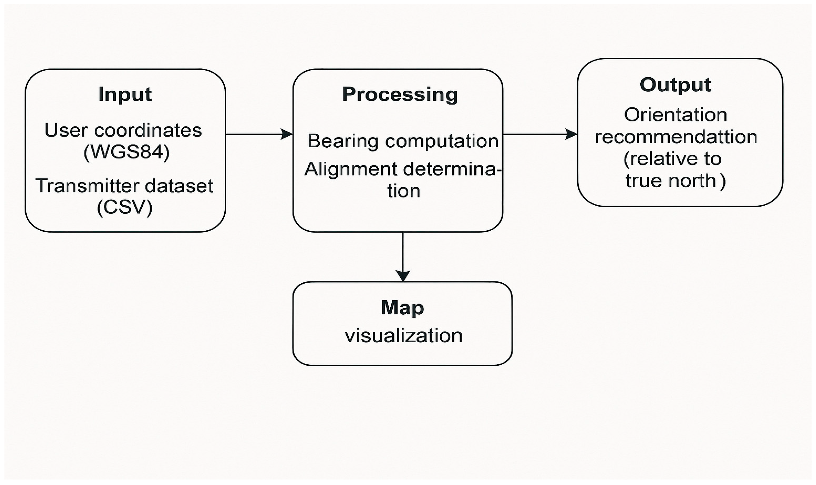
In addition to its computational simplicity, the methodology emphasizes practicality and accessibility. The system functions as a low-cost software-based solution that can assist users in properly orienting directional receiving antennas without requiring specialized measurement equipment or professional field surveys. Beyond home installations, the same methodology can be extended to broader applications involving the deployment of temporary reception setups in remote, inaccessible, or hazardous environments where manual antenna alignment is impractical. An overview of the alignment system architecture is presented in Figure 1.
By incorporating a structured CSV dataset, a Python-based processing engine (version 3.15, Python Software Foundation, Wilmington, DE, USA), and an optional mapping module, the methodology ensures that alignment recommendations are both transparent and reproducible. The graphical interface further enhances usability by allowing the user to obtain orientation guidance without interacting directly with geospatial formulas or antenna models. In this way, the proposed approach provides a practical and reliable solution for antenna pointing, suitable even in scenarios where specialized measurement equipment is unavailable.

2.1. The Initial Bearing Formula

The Initial Bearing, or Forward Azimuth, is the angle that specifies the direction from one point on the Earth’s surface toward another. It is derived from the respective latitudes and longitudes of the two locations and expresses the heading relative to true north that a receiver or observer must face to point toward the target position [8].
Mathematically: (ϕ1, λ1): latitude and longitude of the starting point. (ϕ2, λ2): latitude and longitude of the destination point
θb = atan2(sinλ) × cos(ϕ2), cos(ϕ1) × sin(ϕ2) − sin(ϕ1) × cos(ϕ2) × cosλ))
where (ϕ1, λ1) denote the latitude and longitude of the user location (start point) and (ϕ2, λ2) the latitude and longitude of the transmitter site (destination point), expressed in radians. The longitude difference is defined as Δλ = λ2λ1.
Equation (1) corresponds to the standard initial bearing (forward azimuth) formulation derived from spherical trigonometry and is widely used in navigation and geodesy. It should not be confused with the haversine formula, which is employed for great-circle distance estimation. The bearing formulation provides the directional heading relative to true north from the user location toward the transmitter site.
Equation (1) yields the initial bearing θb in radians. The result is converted to degrees and normalized to the range [0°, 360°) prior to subsequent processing.

2.2. Angular Deviation Between User Bearing and Sector Azimuth

Once the geodesic bearing θb from the user to each transmitter site is obtained, the system evaluates how closely this direction aligns with the main-lobe azimuth of each broadcast sector. Because azimuthal quantities wrap around at 0° and 360°, a standard linear subtraction would yield misleading results near the angle boundary.
In the following analysis, all azimuthal quantities (bearing, sector azimuth, and angular deviation) are expressed in degrees unless explicitly stated otherwise. To address this, the system computes the cyclic angular deviation using a normalized circular-difference expression, using the formula below:
Δ θ = min ( θ b θ s ,   360 ° θ b θ s )
where θs denotes the azimuth of the corresponding transmission sector. The use of the minimum function ensures that the computed angular deviation corresponds to the shortest angular distance between two directions on a circular scale. This is necessary because azimuthal angles are defined modulo 360°, and direct subtraction may lead to misleadingly large differences near the 0°/360° boundary.

2.3. Beamwidth-Based Alignment Evaluation

Each broadcast antenna sector is characterized by a half-power beamwidth (HPBW), denoted as β. This parameter defines the angular region where transmitted power remains within approximately −3 dB of the peak value. To determine whether the user lies within the effective radiation region, the deviation is compared against the half-beamwidth threshold:
Δ θ β 2
If this condition holds, the user is considered to fall inside the main lobe of the sector; otherwise, they fall outside. For practical interpretation, three qualitative alignment categories are defined based on fractional ranges of the beamwidth:
Excellent alignment:
Δ θ β 6
Very good alignment:
β 6 < Δ θ β 3
Marginal alignment:
β 3 < Δ θ β 2
These thresholds provide intuitive guidance to the user, reflecting the progressive attenuation experienced as the boresight direction diverges from the receiver’s position.
The subdivision of the beamwidth into qualitative alignment categories is not intended to represent strict physical boundaries, but rather practical engineering guidelines that reflect the progressive attenuation experienced as the receiver deviates from the antenna boresight direction. Although real antenna radiation patterns exhibit non-linear power roll-off characteristics, side lobes, and asymmetries, the adopted beamwidth subdivision is intentionally formulated as a simplified engineering heuristic. The objective is not to model detailed electromagnetic behavior, but to provide an intuitive and stable classification framework suitable for deterministic geometric alignment. The thresholds therefore serve as interpretability-driven guidelines rather than strict physical performance limits.
The specific fractional thresholds adopted in this study (1/6 and 1/3 of the beamwidth) were selected to balance sensitivity and interpretability and can be readily adjusted depending on antenna characteristics or installation requirements.

2.4. Sector Selection Based on Minimum Deviation

After computing the angular deviation for every transmission sector, the system identifies the sector that provides the closest directional match to the user’s bearing. This is achieved by comparing all deviation values and selecting the sector for which the deviation is the smallest. In practice, this means that the system chooses the transmission lobe whose pointing direction most closely aligns with the direction from the user toward the site. This selection criterion offers a clear and deterministic rule: the recommended sector is simply the one exhibiting the least angular separation from the user’s line of sight.
If strict alignment conditions are required, the comparison is restricted only to those sectors for which the deviation falls within the half-power beamwidth, ensuring that the user lies inside the effective radiating region. When no sector satisfies this condition, the system still identifies the geometrically closest sector by deviation ranking, thereby ensuring that a practical recommendation is provided even under suboptimal conditions. This decision step represents the final stage of the alignment analysis and forms the basis for the orientation instruction delivered to the user.
The proposed framework is designed to be antenna-agnostic and can be applied to any directional receiving antenna whose radiation characteristics can be approximated by a main-lobe azimuth and an effective beamwidth. In practical digital terrestrial television reception, this includes widely used antenna types such as Yagi–Uda and log-periodic arrays, which exhibit well-defined directional patterns.
In contrast, omnidirectional antennas, such as monopole or dipole configurations, do not provide directional gain and therefore fall outside the scope of the proposed alignment methodology. The framework is specifically intended for scenarios where antenna orientation directly influences reception performance through directional selectivity.

3. Results and Discussion

To comprehensively assess the performance of the proposed antenna-alignment system, three experimental scenarios were formulated using real broadcast parameters from the Ymittos and Parnitha transmission sites operated by the Hellenic Broadcasting Corporation (ERT). These experiments were designed to (i) verify the correctness of the geometric computations, (ii) evaluate the robustness of the alignment logic under varying user–transmitter configurations, and (iii) examine the interpretability of the recommendations produced by the system’s orientation engine and optional visualization module.
The selected scenarios correspond to three representative operational conditions: (i) user locations entirely outside all transmitting sectors, resulting in marginal or degraded alignment performance; (ii) user locations well within a sector’s main lobe, yielding optimal alignment conditions; and (iii) boundary cases in which the user is positioned near the edge of a beamwidth region, leading to ambiguous yet operationally relevant outcomes. All experiments were conducted using real geospatial coordinates and authentic sector azimuth patterns to ensure that the evaluation reflects realistic deployment environments.

3.1. Case Study 1—User Outside All Main Lobes

In the first scenario, the user was located at
(37.99000° N, 23.73000° E)
with the Ymittos broadcast site serving as the reference transmitter. The geospatial engine computed an initial bearing of approximately
θb = 126.9°
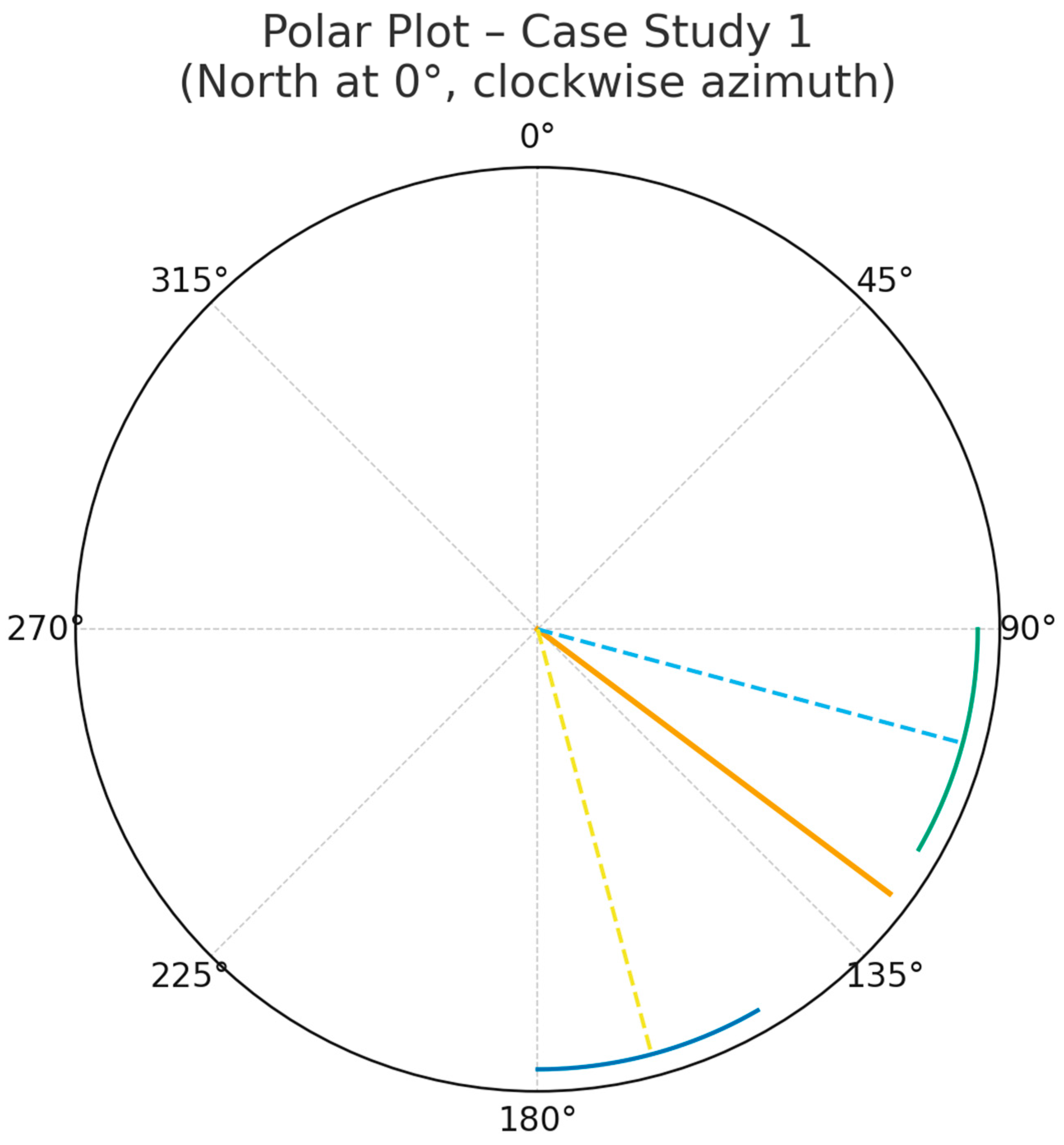
Figure 2 illustrates the spatial relationship between user and transmitter, including the straight-line bearing direction.
Figure 2 presents a polar visualization of the directional geometry involved in the antenna alignment process for Case Study 1. The solid radial line corresponds to the computed bearing from the user toward the transmitter, representing the ideal heading that the receiving antenna must be oriented toward. The two dashed lines denote the azimuth orientations of the transmitter’s active sectors, each accompanied by an angular arc depicting the sector’s main-lobe beamwidth. Although the user’s bearing does not fall within the main-lobe region of either sector, it lies closer to the 105° sector, indicating a smaller angular deviation relative to that direction. This graphical representation enables a clear understanding of how user–transmitter geometry influences signal reception quality and supports the selection of the most appropriate sector based purely on geospatial alignment criteria.

3.2. Case Study 2—User Well Inside a Main Lobe

A second experiment examined an ideal condition in which the user lies comfortably within the radiated power lobe of a specific sector. The user location was set to
(38.02000° N, 23.80000° E)
With reference again to the Ymittos transmitter. The system computed a bearing of
θb = 350°
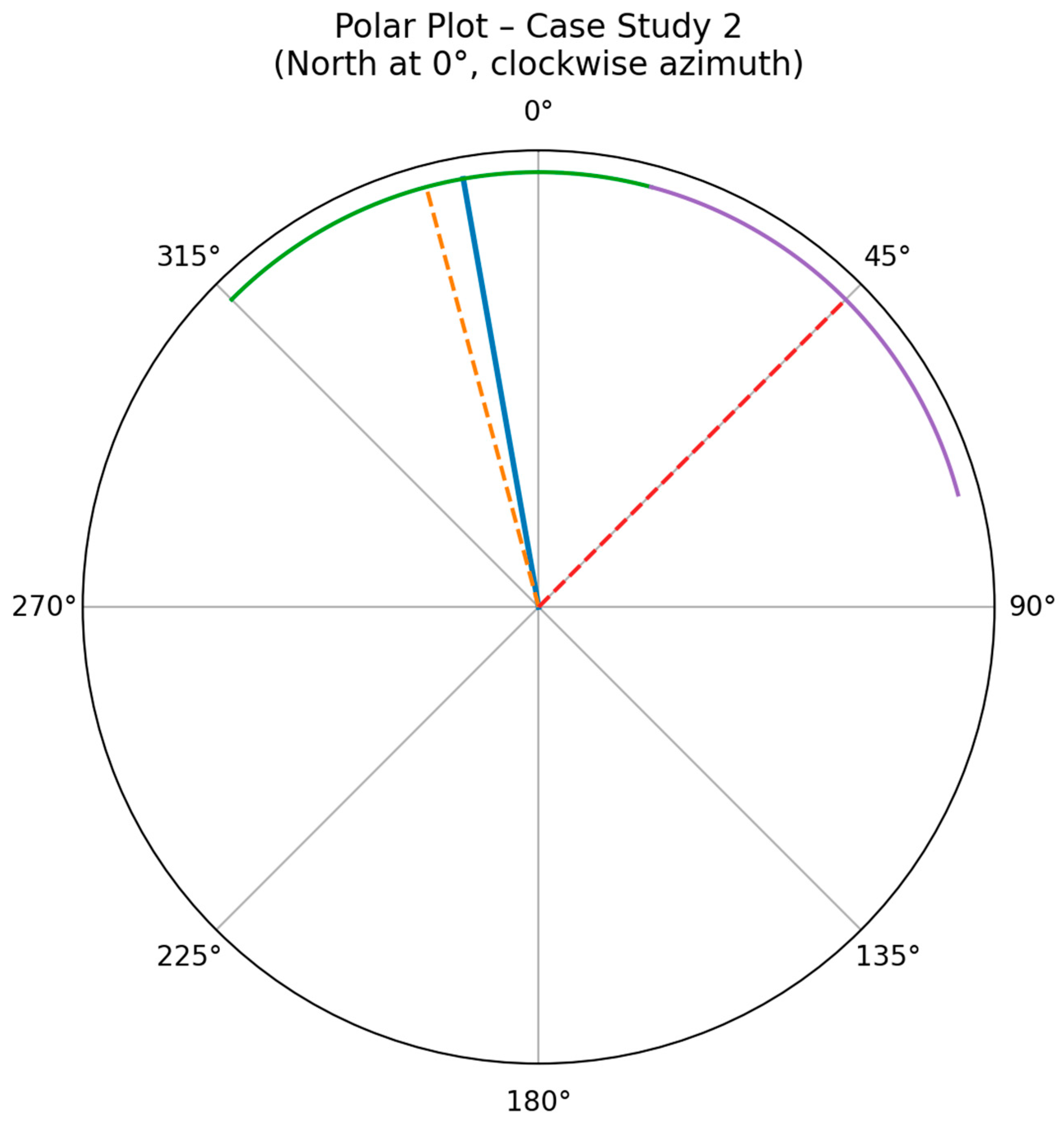
Two sectors were evaluated: one with azimuth 345° and beamwidth 60°, and another with azimuth 45° and identical beamwidth. The deviations were calculated as 5° and 55°, respectively. Since the 5° deviation lies well within the ±30° beamwidth region, the system correctly classified this alignment as excellent. Figure 3 illustrates this geometry, showing a nearly collinear user–transmitter path relative to the selected sector.
Figure 3 illustrates the polar representation of the directional geometry associated with Case Study 2, where the user is positioned well within the main radiation lobe of a broadcast sector. The solid radial line indicates the bearing from the user toward the transmitter, corresponding to the optimal orientation of the receiving antenna. The dashed radial lines denote the azimuth directions of the available transmission sectors, with the associated beamwidths visualized as angular arcs. In this configuration, the bearing intersects the beamwidth region of the sector oriented at 345°, resulting in a minimal angular deviation and a strong geometric alignment. Conversely, the sector oriented at 45° exhibits a substantially larger deviation and does not contribute to effective coverage at the user’s location. This visualization confirms the numerical evaluation of alignment quality and demonstrates the system’s ability to identify optimal reception conditions based solely on azimuthal geometry.

3.3. Case Study 3: Near-Boundary Alignment Conditions

In this scenario, the user was located at geographic coordinates (38.0115° N, 23.7552° E), while the broadcast transmission site was positioned at (37.9583° N, 23.8183° E). Using the geodesic bearing formulation described in Section 3, the bearing angle from the user toward the transmitter was computed as θβ = 92°, representing the direction in which the receiving antenna should ideally be oriented.
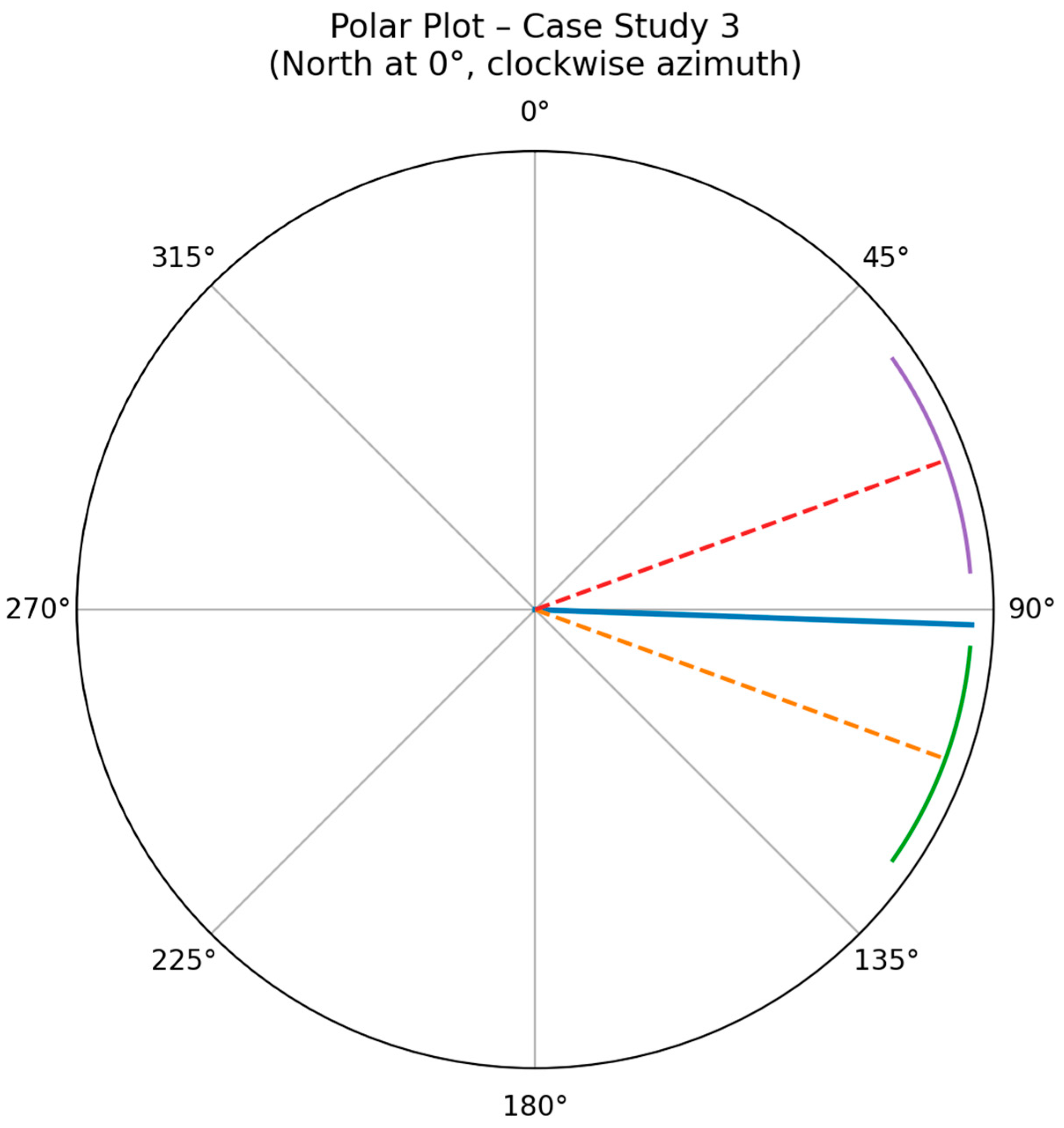
The transmission site employed two directional broadcast sectors with azimuth orientations of 70° and 110°, each characterized by a beamwidth of 30° (±15°). The angular deviation between the user bearing and the 110° sector was calculated as Δθ = 18°, placing the user marginally outside the half-power beamwidth of the main radiation lobe. In contrast, the deviation relative to the 70° sector exceeded 22°, indicating a significantly weaker geometric alignment.
Figure 4 presents the polar representation of the user bearing and transmitter sector orientations for Case Study 3; the bearing line lies just outside the beamwidth envelope of the 110° sector. This visual evidence confirms the near-boundary alignment condition identified by the numerical analysis. Although the bearing does not strictly fall within the main-lobe region of either sector, the proposed method correctly identifies the 110° sector as the closest geometrical match. This case study demonstrates the system’s ability to provide meaningful alignment recommendations even when the user is positioned at the edge of directional coverage, while simultaneously indicating the expected limitations in reception quality.

3.4. Summary

Table 1 summarizes the geometric alignment results obtained from the three experimental case studies, providing a comparative overview of system performance under varying directional conditions. In Case Study 1, the computed bearing lies outside the main-lobe regions of both available transmission sectors, resulting in a relatively large angular deviation. This scenario represents a sub-optimal alignment condition, where reception is expected to be weaker due to the lack of direct main-lobe coverage, despite the identification of the closest sector based on minimum angular deviation.
In contrast, Case Study 2 demonstrates an ideal alignment configuration, where the user bearing falls well within the beamwidth of the sector oriented at 345°. The resulting minimal angular deviation confirms strong geometric alignment and favorable reception conditions. This case validates the effectiveness of the proposed method under optimal line-of-sight scenarios.
Case Study 3 represents an intermediate, near-boundary condition, where the bearing lies marginally outside the main-lobe region of the closest sector. Although strict main-lobe alignment is not achieved, the relatively small angular deviation indicates partial directional compatibility. This scenario highlights the system’s capability to provide informative alignment guidance even in ambiguous geometric configurations, while transparently reflecting the expected limitations in signal quality.
The results presented in this section demonstrate the effectiveness of the proposed geospatial alignment methodology under a range of realistic reception scenarios.
It should be emphasized that the objective of the experimental evaluation is to validate the correctness, robustness, and interpretability of the proposed geometric alignment logic rather than to assess received signal strength or propagation performance. The proposed method is intentionally positioned as a deterministic, geometry-based baseline suitable for line-of-sight conditions, upon which empirical signal measurements or propagation-aware models may be incorporated in future extensions.
By relying exclusively on bearing–azimuth geometry and publicly available transmitter data, the geometry-based methodology is able to provide meaningful orientation recommendations for directional television receiving antennas without the need for specialized measurement equipment or signal-level feedback.
A key observation arising from the three case studies is the strong correlation between angular deviation and expected reception quality. In Case Study 2, where the user bearing lies well within the main-lobe beamwidth of the selected transmission sector, the method correctly identifies an optimal alignment configuration characterized by minimal angular deviation. This scenario represents ideal line-of-sight conditions and confirms the validity of using purely geometric criteria for antenna alignment when transmitter radiation patterns are favorably oriented toward the receiver.
In contrast, Case Study 1 illustrates a sub-optimal alignment condition in which the user bearing falls outside the main-lobe regions of all available transmission sectors. Although the method successfully identifies the sector with the smallest angular deviation, the resulting geometry suggests reduced reception performance. This outcome highlights an important limitation of directional broadcast systems, namely that reception quality is inherently constrained by the fixed azimuth orientations of transmitter sectors. Nevertheless, the ability of the proposed approach to quantify and rank alignment alternatives remains valuable, particularly in environments where empirical trial-and-error antenna adjustment would otherwise be required.
Case Study 3 further extends this analysis by examining a near-boundary condition, where the user bearing lies marginally outside the half-power beamwidth of the closest sector. The results demonstrate that even in such ambiguous configurations, the system provides informative guidance by identifying the most geometrically compatible sector while clearly indicating the proximity to the beamwidth limit. This behavior is particularly relevant in dense urban or peri-urban environments, where minor variations in antenna orientation or installation height may significantly affect reception outcomes.
An important strength of the proposed methodology lies in its transparency and interpretability. Unlike data-driven or machine-learning-based approaches, the alignment recommendations are derived from explicit geometric computations that can be easily verified and visualized through polar diagrams and spatial maps. This characteristic not only enhances user trust but also facilitates integration into regulatory, educational, or planning contexts where explainability is essential.
Despite its advantages, the method assumes unobstructed line-of-sight propagation between the user and the transmitter and does not explicitly account for terrain morphology, building obstructions, or multipath effects. These factors may introduce deviations between purely geometric predictions and actual reception conditions, particularly in dense urban environments. Nevertheless, the LOS-based assumption provides a consistent and interpretable baseline for deterministic antenna orientation under well-defined propagation scenarios. While this assumption is reasonable for many broadcast reception scenarios, particularly in elevated or suburban locations, future extensions could incorporate digital elevation models, clutter databases, or empirical signal measurements to further refine alignment assessments.
An additional practical consideration relates to the frequency-dependent behavior of real antennas. Radiation patterns, gain characteristics, and effective beamwidths may vary across operating bands, particularly in multi-band antenna designs. While the proposed geometry-based alignment logic assumes static sector parameters, frequency-dependent variations may influence the effective reception conditions. Such effects have been widely discussed in multi-band antenna studies [9].
Overall, the discussion of the experimental results confirms that the proposed geospatial alignment tool offers a lightweight yet effective solution for directional antenna orientation, providing practical guidance across a spectrum of reception conditions while maintaining a clear and interpretable computational framework.
A qualitative comparison with commonly used antenna alignment approaches further clarifies the positioning of the proposed method. Traditional alignment practices in broadcast engineering are often based on manual orientation and iterative trial-and-error procedures, guided by empirical signal observations. While such approaches can be effective, they are inherently environment-dependent and lack reproducibility.
Modern smartphone-based applications provide intuitive visual guidance and real-time feedback to the user. However, these systems typically rely on implicit signal measurements, device-specific sensing capabilities, and proprietary processing mechanisms, which limit transparency and may introduce variability depending on environmental conditions and hardware characteristics.
In contrast, the proposed framework follows a fully deterministic and geometry-based methodology, relying exclusively on publicly available broadcast parameters and user geolocation. This enables transparent, reproducible, and computationally efficient alignment recommendations. While the approach does not capture all propagation effects and may be less adaptive in complex environments, it provides a stable and interpretable baseline for antenna alignment, particularly under line-of-sight conditions.
It is important to emphasize that the contribution of this work does not lie in the introduction of new geometric metrics, but in the formalization and integration of established directional parameters into a unified deterministic alignment framework. This distinguishes the proposed approach from conventional ad hoc alignment practices by providing a structured and reproducible methodology. From a user-experience perspective, a trade-off exists between transparency and adaptability. While modern applications offer ease of use and real-time responsiveness, they often operate as black-box systems with limited interpretability. In contrast, the proposed method enables users to understand the underlying alignment logic, enhancing trust and reproducibility, although this may reduce adaptability in scenarios affected by complex propagation conditions.
It is important to note that antenna performance is also influenced by material properties, structural design, and operating frequency characteristics. Recent studies have explored advanced modeling approaches for wireless systems, including stochastic geometry-based frameworks for non-terrestrial networks [10], as well as the use of flexible dielectric materials in antenna and RF sensor design [11]. While such approaches provide deeper insight into electromagnetic behavior and system-level performance, they are beyond the scope of the present geometry-based alignment framework.
Nevertheless, the integration of material-aware antenna models and advanced propagation techniques represents a promising direction for future work, potentially enhancing the accuracy of alignment recommendations in complex environments.

4. Conclusions and Future Directions

This study investigated the development of a lightweight, geometry-based tool for the automated alignment of directional television receiving antennas using publicly available broadcast infrastructure data. By integrating geospatial information from user-defined coordinates with technical parameters of terrestrial broadcast sites, the proposed method enables the determination of optimal antenna orientation through deterministic bearing and angular deviation computations.
The experimental evaluation, conducted across multiple case studies, demonstrated the system’s ability to distinguish between optimal, near-boundary, and sub-optimal alignment conditions based solely on azimuthal geometry. Through polar visualizations and quantitative deviation analysis, the proposed approach successfully identified the most geometrically compatible transmission sector for each scenario, while transparently indicating expected limitations in reception quality when main-lobe coverage was not achieved.
The proposed solution is particularly suitable for reception environments where line-of-sight conditions are dominant and rapid, low-cost antenna alignment is required without the use of specialized measurement equipment. Its transparent computational framework, minimal data requirements, and ease of implementation make it well suited for practical deployment, educational use, and preliminary coverage assessment. Overall, this work highlights the potential of simple geospatial modeling techniques to support practical broadcast reception tasks, offering a reliable and interpretable alternative to more complex data-driven or hardware-intensive approaches.
Future work may extend the proposed framework by incorporating propagation-aware models, digital elevation data, and clutter information to account for non-line-of-sight conditions and environmental effects. In addition, the integration of empirical signal measurements could further enhance the accuracy and robustness of the alignment recommendations. Another promising direction involves the adaptation of the methodology to other communication systems, including emerging wireless and broadcast infrastructures, where directional alignment remains a critical factor for system performance.

Author Contributions

Methodology, K.Z.; Formal analysis, K.Z.; Writing—original draft, K.Z.; Supervision, G.D.; Project administration, K.Z. All authors have read and agreed to the published version of the manuscript.

Funding

This research received no external funding.

Institutional Review Board Statement

Not applicable.

Informed Consent Statement

Not applicable.

Data Availability Statement

The original contributions presented in the study are included in the article, further inquiries can be directed to the corresponding author.

Conflicts of Interest

The authors declare no conflict of interest.

References

  1. Balanis, C.A. Antenna Theory: Analysis and Design; Wiley: Hoboken, NJ, USA, 2016. [Google Scholar]
  2. Ziółkowski, C.; Kelner, J.M.; Krygier, J.; Chandra, A.; Prokeš, A. Radio Channel Capacity with Directivity Control of Antenna Beams in Multipath Propagation Environment. Sensors 2021, 21, 8296. [Google Scholar] [CrossRef] [PubMed]
  3. D’Andreagiovanni, F.; Lakhlef, H.; Nardin, A. A Matheuristic for Joint Optimal Power and Scheduling Assignment in DVB-T2 Networks. Algorithms 2020, 13, 27. [Google Scholar] [CrossRef]
  4. Yang, H.; Herben, M.H.A.J.; Akkermans, I.J.A.G.; Smulders, P.F.M. Impact Analysis of Directional Antennas and Multiantenna Beamformers on Radio Transmission. In IEEE Transactions on Vehicular Technology; IEEE: Piscataway, NJ, USA, 2008; Volume 57, pp. 1695–1707. [Google Scholar] [CrossRef]
  5. Sheikh, R.A.; Al-Hadi, A.A.; Sabapathy, T.; Mirza, H.; Hossain, T.M.; Akkaraekthalin, P.; Soh, P.J. Review of Positioning Technologies and Antenna Designs for Indoor, Outdoor, and Wearable Applications. IEEE Access 2025, 13, 180317–180343. [Google Scholar] [CrossRef]
  6. Ilori, A.O.; Amusa, K.A.; Erinosho, T.C.; Imoize, A.L.; Idowu, O.A. Pathloss Estimation of Digital Terrestrial Television Communication Link Within the UHF Band. Telecom 2025, 6, 97. [Google Scholar] [CrossRef]
  7. Skentos, A. Combining Digital Elevation Data, Expert Knowledge and GIS for Geomorphological Mapping; The Case Study of Mount Hymettus, Athens, Greece. Ann. Valahia Univ. Targoviste Geogr. Ser. 2018, 18, 23–32. [Google Scholar] [CrossRef]
  8. International Telecommunication Union Radiocommunication Sector (ITU-R). Methods for the Evaluation of Coverage of Digital Terrestrial Television Broadcasting Systems; Report ITU-R BT.2468-2; ITU: Geneva, Switzerland, 2024. [Google Scholar]
  9. Wang, S.; Kong, F.; Li, K.; Du, L. A planar triple-band monopole antenna loaded with an arc-shaped defected ground plane for WLAN/WiMAX applications. Int. J. Microw. Wirel. Technol. 2020, 13, 381–389. [Google Scholar] [CrossRef]
  10. Wang, R.; Kishk, M.A.; Alouini, M.-S. Modeling and analysis of non-terrestrial networks by spherical stochastic geometry: A survey. IEEE Commun. Surv. Tutor. 2025, 28, 1879–1905. [Google Scholar] [CrossRef]
  11. Hussain, M.; Zahra, H.; Abbas, S.M.; Zhu, Y. Flexible dielectric materials: Potential and applications in antennas and RF sensors. Adv. Electron. Mater. 2024, 10, 2400240. [Google Scholar] [CrossRef]
Figure 1. An overview of the alignment system architecture.
Applsci 16 03561 g001
Figure 2. Polar representation of user bearing and transmitter sector orientations for Case Study 1.
Applsci 16 03561 g002
Figure 3. Polar representation of user bearing and transmitter sector orientations for Case Study 2.
Applsci 16 03561 g003
Figure 4. Polar representation of user bearing and transmitter sector orientations for Case Study 3.
Applsci 16 03561 g004
Table 1. Summary of geometric alignment results obtained from the three experimental case studies.
Scen.User (Lat./Lon.)Bearing θβ (°)TX (Lat./Lon.)Sector Azimuths (°)Beamwidth (°)Minimum Δθ (°)Alignment Condition
Case 1(37.99, 23.73)126.9(37.95, 23.81)105, 1653021.9Outside main lobe
Case 2(38.02, 23.80)350.0(37.95, 23.81)345, 45605.0Inside main lobe
Case 3(38.01, 23.76)92.0(37.95, 23.81)70, 1103018.0Near-boundary
Disclaimer/Publisher’s Note: The statements, opinions and data contained in all publications are solely those of the individual author(s) and contributor(s) and not of MDPI and/or the editor(s). MDPI and/or the editor(s) disclaim responsibility for any injury to people or property resulting from any ideas, methods, instructions or products referred to in the content.