Review

Ultrasonic Nondestructive Evaluation of Welded Steel Infrastructure: Techniques, Advances, and Applications


1
LANDTIE Research Lab, Department of Civil Engineering, Georgia Southern University, Statesboro, GA 30458, USA
2
Department of Mechanical Engineering, Georgia Southern University, Statesboro, GA 30458, USA
3
Department of Construction Management, Kennesaw State University, Marietta, GA 30060, USA
4
LANDTIE Research Lab, Department of Manufacturing Engineering, Georgia Southern University, Statesboro, GA 30458, USA
*
Author to whom correspondence should be addressed.
Appl. Sci. 2026, 16(7), 3206; https://doi.org/10.3390/app16073206
Submission received: 20 February 2026 / Revised: 20 March 2026 / Accepted: 23 March 2026 / Published: 26 March 2026
(This article belongs to the Special Issue Application of Ultrasonic Non-Destructive Testing—Second Edition)

Abstract

Welding is a critical joining process in civil and transportation infrastructure, enabling the fabrication of complex steel structural systems used in bridges, buildings, and other essential infrastructures. Despite strict adherence to established welding codes and standards, such as AWS D1.1 and AASHTO/AWS D1.5, welding flaws and service-induced defects can occur in welded components. Cause of defects and their structural impact, along with detection, sizing, and localization of these anomalies and flaws, are crucial for adequate maintenance, repair, or replacement planning without compromising the functionality of in-service components. Among available NDT techniques, ultrasonic testing (UT) remains one of the most widely adopted methods of weld inspection due to its depth of penetration, sensitivity to internal defects, and suitability for field deployment. Recent advancements in ultrasonic technologies, particularly Phased Array Ultrasonic Testing (PAUT), along with its emerging approaches such as Full Matrix Capture (FMC) and the Total Focusing Method (TFM), have significantly enhanced inspection accuracy, repeatability, and interpretability. These techniques enable flexile beam steering, multi-angle interrogation, and improved imaging of complex geometries. This paper presents a comprehensive review of PAUT for the inspection of welded steel infrastructure adhering to the recommendations and requirements of the relevant codes and standards, synthesizing the current literature on PAUT principles, wave modes, probe configurations, and data acquisition strategies. Emphasis is placed on the practical implementation of PAUT in civil infrastructure inspection, its advantages over conventional NDT methods, and its potential to support informed decisions related to quality acceptance, repair, and long-term maintenance planning. This paper concludes by identifying current challenges and future research directions for advanced ultrasonic inspection of welded steel structures.

1. Introduction

1.1. Role of Welded Steel in Infrastructure

Welded steel structures form the backbone of modern civil and transportation infrastructure, including bridges, buildings, and other critical facilities. Their widespread adoption is driven by favorable mechanical properties such as high strength, ductility, and adaptability to complex geometries, which enable efficient structural systems across a wide range of loading and environmental conditions [1,2]. The safety and adequate functioning of these infrastructures depend not only on accurate design and construction practices, but critically on effective inspection and quality assessment throughout their service life. In transportation infrastructure in particular, welded steel enables long spans, modular construction, and rapid fabrication [3,4,5]. As a result, welded steel components are universal in both new construction and legacy infrastructure systems. The performance of these systems is therefore inseparable from the integrity of their welded connections.
As infrastructure systems continue to age, inspection outcomes increasingly influence decisions related to maintenance, repair, and long-term serviceability. Many steel bridges and transportation structures currently in service were designed for lifespans of 50–75 years and are now operating beyond their original design assumptions [6]. Under these conditions, inspection outcomes increasingly influence maintenance prioritization, repair decisions, and risk management strategies [7,8,9]. Consequently, nondestructive evaluation (NDE) has become a central component of infrastructure stewardship. Reliable inspection methods are essential to ensure continued serviceability while avoiding unnecessary interventions through destructive methods.

1.2. Welded Joints as Critical Structural Regions

Welded joints represent some of the most critical regions within steel infrastructure due to their role in force transfer and geometric discontinuity. Unlike rolled or plate members, welded connections introduce changes in geometry that produce localized stress concentrations [3]. In addition, the welding process introduces residual stress and alters the local microstructure within the welding metal and heat-affected zone (HAZ) [3,10,11]. These combined effects create regions of elevated vulnerability within otherwise robust structural systems. Consequently, the behavior of welded joints often governs the overall performance of steel infrastructure.
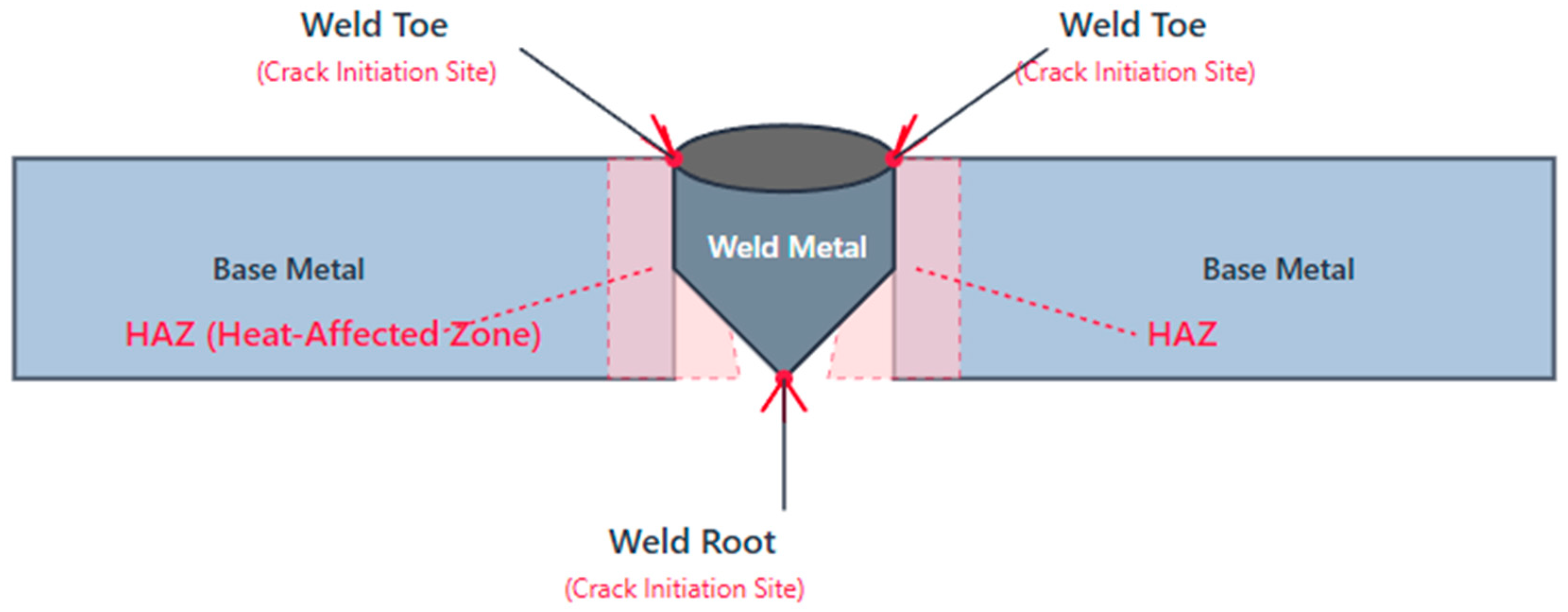
Under service loading, welded joints are particularly susceptible to fatigue damage [12]. As displayed in Figure 1, fatigue cracks frequently initiate at weld toes, weld roots, or fusion boundaries, where local stresses are highest. Once initiated, cracks can propagate under cyclic loading even when nominal stress levels remain below yield strength [13,14,15,16,17]. Environmental factors such as corrosion, moisture ingress, and temperature variation can further accelerate crack growth [18,19]. Consequently, small weld discontinuities that are initially benign may evolve into critical defects over time.
The disproportionate influence of welded joints on structural reliability has made them a primary focus of inspection planning in steel infrastructure. Failure of a single welded connection can compromise load paths and lead to partial or total structural collapse, particularly in nonredundant steel tension or fracture-critical members [20,21,22,23]. This risk underscores the importance of not only detecting weld discontinuities, but also accurately characterizing their size, orientation, and location. Inspection techniques applied to welded joints must therefore meet more stringent performance requirements than those used for base material evaluation. Accurate weld assessment is essential for preventing progressive deterioration and sudden failure.

1.3. Motivation for In-Service Inspection

Nondestructive testing (NDT) techniques are preferred for the inspection of welded steel infrastructure because they allow evaluation without damaging the structure or interrupting service. This capability is especially important for bridges and transportation systems, where closures or destructive sampling can impose significant economic and societal costs [23]. In-service inspection enables engineers to assess structural condition while maintaining operational functionality. As infrastructure networks expand and age simultaneously, reliance on nondestructive inspection continues to increase [8,24,25]. Effective NDT is therefore indispensable to modern infrastructure management.
In-service inspection also supports condition-based maintenance strategies by providing data-driven insight into structural health. Rather than relying solely on prescriptive inspection intervals, engineers can use inspection results to prioritize repairs and allocate resources more efficiently [26]. This approach is particularly valuable for welded steel infrastructure, where deterioration mechanisms are often localized and defect growth rates vary widely. Accurate in-service inspection allows for early detection of damage and timely intervention. This reduces both safety risks and lifecycle costs.
A variety of NDT methodologies, such as dye penetrant testing, magnetic particle testing, and eddy current inspection, exist for the inspection of welded steel infrastructure. Among these, ultrasonic testing (UT) remains one of the most widely adopted methods for weld inspection. UT offers deep penetration while still being capable of identifying surface defects, sensitivity to internal defects, and adaptability to field conditions, making it well suited for steel infrastructure applications [27,28,29,30,31]. However, as structural systems become more complex and performance expectations increase, limitations in conventional UT have become more apparent. These limitations have driven the development of advanced ultrasonic inspection techniques capable of improving coverage, repeatability, and defect characterization. The evolution of ultrasonic methods reflects the growing demands placed on in-service inspection.

2. Welding Practices and Defect Mechanisms in Steel Infrastructure

2.1. Welding Processes and Joint Types

Arc welding processes are commonly used in the fabrication of steel infrastructure components, both in controlled shop environments and, to a lesser extent, in field applications. Common techniques include Shielded Metal Arc Welding (SMAW), Gas Metal Arc Welding (GMAW), Flux-Cored Arc Welding (FCAW), and Gas Tungsten Arc Welding (GTAW) [30,31]. Each process offers distinct advantages related to deposition rate, accessibility, and control of weld quality [32]. The selection of a welding process depends on material type, joint geometry, construction constraints, and environmental conditions. These choices directly influence weld quality and long-term performance.
The welding process also governs heat input and cooling behavior, which in turn affects microstructural evolution within the weld metal and HAZ [10,11]. Excessive heat input can lead to grain coarsening and reduced toughness, while insufficient heat input may result in lack of fusion or incomplete penetration [33]. Cooling rate influences residual stress distribution and susceptibility to hydrogen-related cracking. These metallurgical effects play a critical role in defect formation and fatigue performance [3,34,35]. As a result, welding practice and structural performance are closely intertwined.
Structural steel members are joined using a variety of welded joint configurations, including butt joints, fillet joints, and T-joints. Each joint type serves a distinct structural function and introduces different geometric conditions that affect stress distribution and inspection accessibility [3,36,37]. From an inspection perspective, joint geometry strongly influences ultrasonic wave propagation, reflection behavior, and coverage [38]. Complex geometries can produce overlapping reflections and geometric echoes that complicate defect detection. Consequently, joint configuration must be considered when selecting and applying nondestructive evaluation techniques.

2.2. Weld Defects and Discontinuities

Weld imperfections are commonly classified using the terms discontinuity, flaw, and defect. A discontinuity refers to a lack of homogeneity within the weld or adjacent base material, while a defect denotes a discontinuity that exceeds acceptance criteria defined by applicable standards [39]. The distinction between these terms is critical, as not all detected discontinuities require repair. Proper classification relies on accurate characterization rather than simple detection. This distinction places significant demands on inspection accuracy and interpretation.
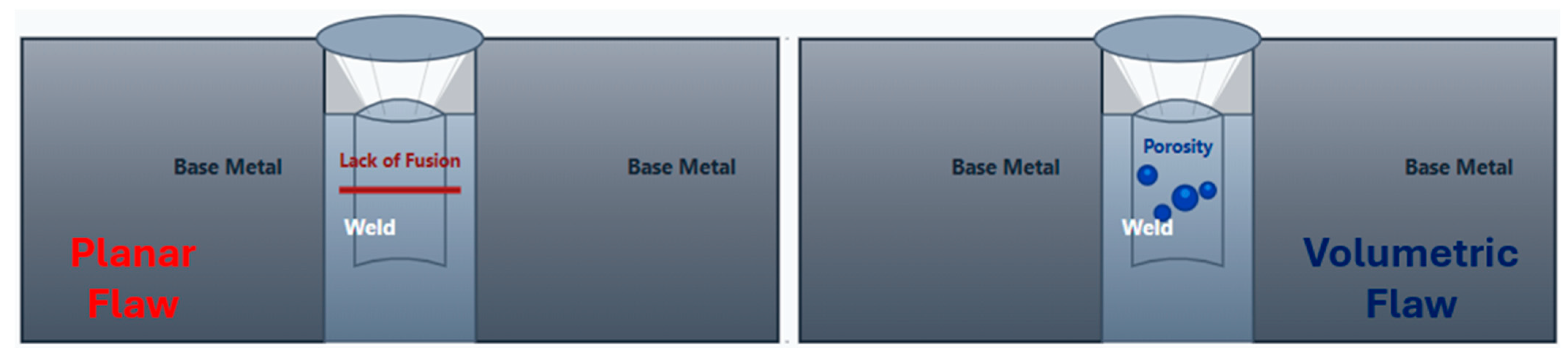
Weld discontinuities are generally categorized as planar, volumetric, or crack-like in nature, outlined in Table 1. Volumetric discontinuities such as porosity and slag inclusions often arise from improper shielding, contamination, or cooling conditions during welding [40]. Planar discontinuities, including lack of fusion and lack of penetration, are frequently associated with insufficient heat input or poor joint preparation [41]. An example of planar versus volumetric discontinuities for better visualization is displayed in Figure 2. Crack-like defects may result from hydrogen embrittlement, residual stress, or fatigue damage. Each defect type interacts differently with ultrasonic waves, producing distinct inspection responses [42].
Accurate characterization of weld defects, including size, orientation, and locations is essential for informed acceptance decisions and maintenance planning [43,44]. Underestimation of critical planar or crack-like defects may compromise structural safety, particularly in fatigue-sensitive components. Conversely, overestimation of benign discontinuities can lead to unnecessary repairs, increased costs, and service disruptions. These competing risks highlight the need for inspection methods that provide reliable sizing and interpretation. Effective weld inspection must therefore balance sensitivity, accuracy, and practical applicability.
Table 1. Relationship between weld discontinuity type, formation mechanism, ultrasonic detectability, and structural significance in steel infrastructure.
Weld DiscontinuityTypical CauseUltrasonic DetectabilityStructural Significance
Lack of FusionImproper heat input, incorrect electrode angle, poor joint preparation.High when beam is normal to plane; low if parallel; strong specular reflection [45].Severe: crack-like planar defect; common fatigue crack initiator.
Incomplete PenetrationInsufficient root opening, low heat input, misalignment.High with proper angle beam; tip diffraction visible [45].Severe: behaves as pre-existing crack at root.
Cracks (hot, cold, fatigue)Residual stress, hydrogen embrittlement, cyclic loading.Very high using diffraction-based methods (TOFD/PAUT); orientation sensitive [46].Critical: fracture-controlled failure mechanism.
Slag InclusionPoor cleaning between passes, improper technique in SMAW/FCAW.Depends on size and orientation; often irregular reflections [45].Moderate: stress concentration but not always fracture-critical.
PorosityGas entrapment, contamination, moisture.Depends on diffuse scattering, low amplitude [47].Low: if clustered, it will reduce effective area.
UndercutExcessive travel speed, improper parameters.Poor detectability; surface breaking but shallow; better visually detected [47].Moderate: fatigue initiation at toe.
OverlapLow heat input, incorrect travel angle.Poor detectability; best with visual or surface methods [47].Moderate: fatigue initiation at toe.
TearingThrough-thickness shrinkage strain in rolled plate.Visualized as a layered reflector pattern [47].Severe: in restrained joints; brittle fracture risk
Burn ThroughExcessive heat input, thin section.Easily detected due to geometry change [47].Local reduction in section capability.
Clustered PorosityShielding gas issues, contamination.Moderately detectable; represented as a distributed backscatter region [47].Moderate: reduces effective cross-section and fatigue resistance.

3. Conventional Ultrasonic Testing (UT)

3.1. Ultrasonic Wave Physics

Ultrasonic testing (UT) is fundamentally governed by the physics of elastic wave propagation in solids. In steel infrastructure applications, high-frequency mechanical waves are introduced into the material, with ultrasonic waves that propagate through the inspected component, reflect from interfaces such as material boundaries or defects, and are analyzed to infer the presence of internal discontinuities [48,49,50]. The information that can be extracted from a UT inspection depends on several interrelated parameters, including wave frequency, mode of propagation, transducer characteristics, and the acoustic properties of the inspected material [50,51,52]. Frequency selection governs the trade-off between penetration depth and spatial resolution: lower frequencies improve sensitivity to small discontinuities but suffer from increased attenuation. In welded joints, where section thickness and geometric complexity vary significantly, these trade-offs become particularly consequential [50]. Therefore, understanding wave behavior is not merely theoretical but directionally linked to inspection reliability in infrastructure contexts.
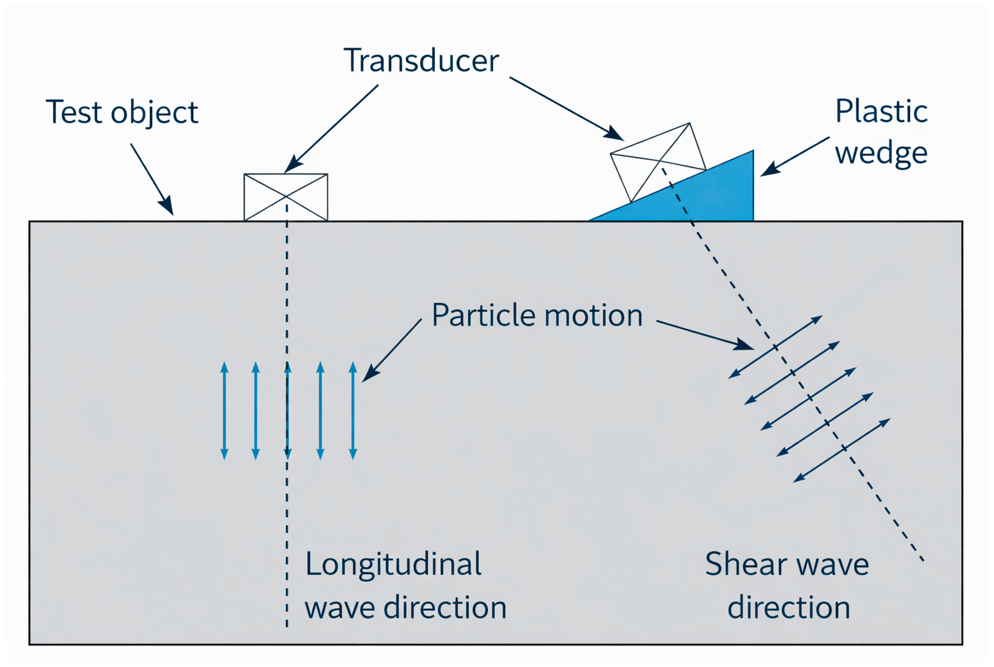
Two primary wave modes observed in Figure 3 are employed in weld inspection: longitudinal waves and shear waves. Longitudinal waves involve particle motion parallel to the direction of propagation and are often used for straight-beam inspections. Shear waves, characterized by particle motion perpendicular to the direction of propagation, are typically generated through angled wedges to interrogate weld fusion zones and planar defects [49,50,53]. When ultrasonic waves encounter interfaces or discontinuities, reflection, refraction, and mode conversion occur in accordance with Snell’s law. In welded joints, where changes in geometry and material properties are abrupt, these interactions become more complex and can produce multiple overlapping signals [50,54]. Accurate interpretation therefore requires not only calibration but also a clear understanding of wave behavior within heterogeneous weld regions [55].
Beam characteristics further influence detection capability. The near-field and far-field regions of a transducer define zones of varying sound pressure distribution, and beam divergence increases as waves propagate beyond the near field. This divergence reduces energy density and spatial resolution, particularly in thick welded sections common in bridge girders and heavy structural members [50,54,56]. Attenuation due to material absorption and scattering further reduces signal amplitude with increasing depth. These phenomena limit defect detectability and sizing accuracy in conventional UT [56]. Consequently, while UT provides powerful volumetric inspection capability, its physics imposes inherent constraints that must be acknowledged in infrastructure applications.

3.2. UT Inspection Practice

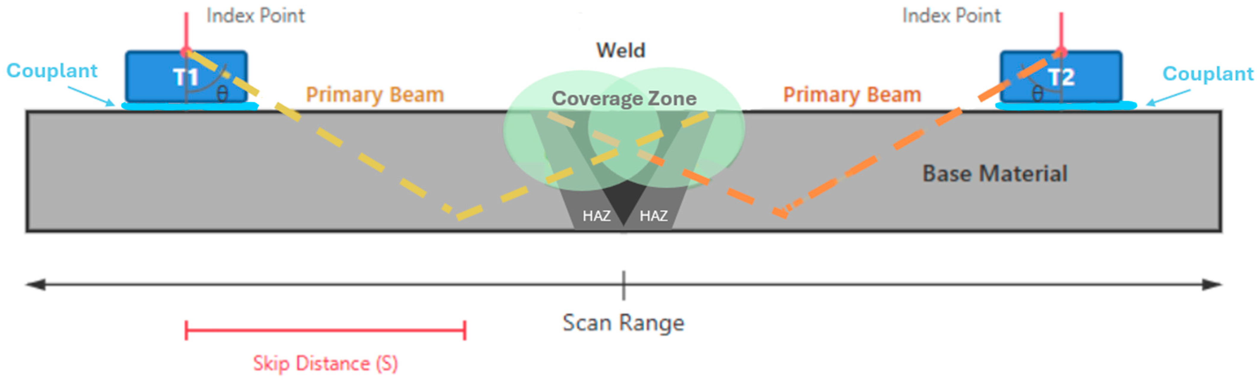
In practice, conventional UT weld inspection employs both straight-beam and angle-beam techniques to interrogate different regions of a welded joint. Angle-beam inspection, as observed in Figure 4 and typically performed at refracted angles such as 45, 60, and 70 degrees, is particularly important for detecting planar discontinuities oriented parallel to the weld axis [50,57]. These inspection configurations are codified in structural welding standards and have been widely implemented in bridges and building inspection protocols. Achieving comprehensive coverage often requires multiple probe positions and repeated scan passes [58]. This reliance on manual manipulation introduces variability and increases inspection time, especially in large infrastructure components [59].
Conventional UT data is typically displayed as A-scans, where signal amplitude is plotted as a function of time or depth. Defect presence is inferred from reflected signal amplitude and time-of-flight measurements [50,55,60]. While this approach is well established, it requires significant operator expertise to distinguish between true defect signals and geometric reflections, back-wall echoes, or mode-converted signals [61]. Complex welded geometries, such as T-joints or multi-pass welds, can generate overlapping reflections that obscure defect indications [62]. Interpretation therefore depends heavily on inspector training and experience.
Amplitude-based sizing techniques further introduce uncertainty. Estimation of defect severity based solely on signal amplitude can lead to underestimation of planar defects that are poorly oriented relative to the beam, or overestimation of benign volumetric indications. This limitation becomes particularly significant in fatigue-sensitive infrastructure components, where crack-like defects pose greater risk than volumetric discontinuities [13,15,49]. Although conventional UT remains widely accepted due to its portability, cost-effectiveness, and established procedural framework, its interpretive subjectivity and limited imaging capability have motivated the development of more advanced ultrasonic methods. In this sense, conventional UT serves both as a foundational technology and as the baseline against which newer techniques are evaluated.
Conventional amplitude-based ultrasonic inspection is particularly challenged, as outlined in Table 2, when inspection results must be interpreted within a structural engineering framework rather than a detection framework. Many weld acceptance criteria ultimately relate to fracture behavior, yet signal amplitude alone does not uniquely correspond to crack size, orientation, or stress intensity relevance [63]. A planar defect that is unfavorably oriented relative to the beam may produce a weak response despite being structurally critical, while a benign volumetric indication may produce a strong reflection. This disconnect complicates the translation of inspection data into engineering decision-making. As infrastructure management increasingly emphasizes reliability and risk-informed assessment, inspection methods must provide information that correlates more directly with structural significance rather than signal magnitude alone.

4. Phased Array Ultrasonic Testing (PAUT)

4.1. PAUT Fundamentals

The development of Phased Array Ultrasonic Testing (PAUT) was driven not solely by a desire for improved imaging, but by the need to reduce uncertainty in weld evaluation [25]. Conventional UT requires multiple probe angles and relies heavily on operator interpretation to infer defect geometry [43]. PAUT extends conventional UT by using an array of individually controlled transducer elements. This is especially useful as weld geometries become thicker and more complex in modern infrastructure, and these limitations increasingly affect inspection reliability and repeatability. PAUT is a method capable of achieving multiple orientations within a single probe position that offers the potential to reduce both missed indications and interpretation variability. PAUT therefore represents not only technological advancement, but a shift toward more deterministic inspection methodology.
PAUT represents a significant evolution of conventional ultrasonic inspection by replacing single-element transducers with multi-element arrays that allow electronic beam control. In PAUT systems, individual elements within the array are excited with precisely controlled time delays, producing constructive and destructive interference patterns that steer and focus the ultrasonic beam [25,64]. This electronic steering enables characterization of multiple angles and focal depths from a single probe position, eliminating the need for repeated mechanical repositioning [42,65,66,67]. As a result, inspection efficiency increases while coverage improves. For welded steel infrastructure, where access may be limited and geometries complex, this flexibility is particularly advantageous.
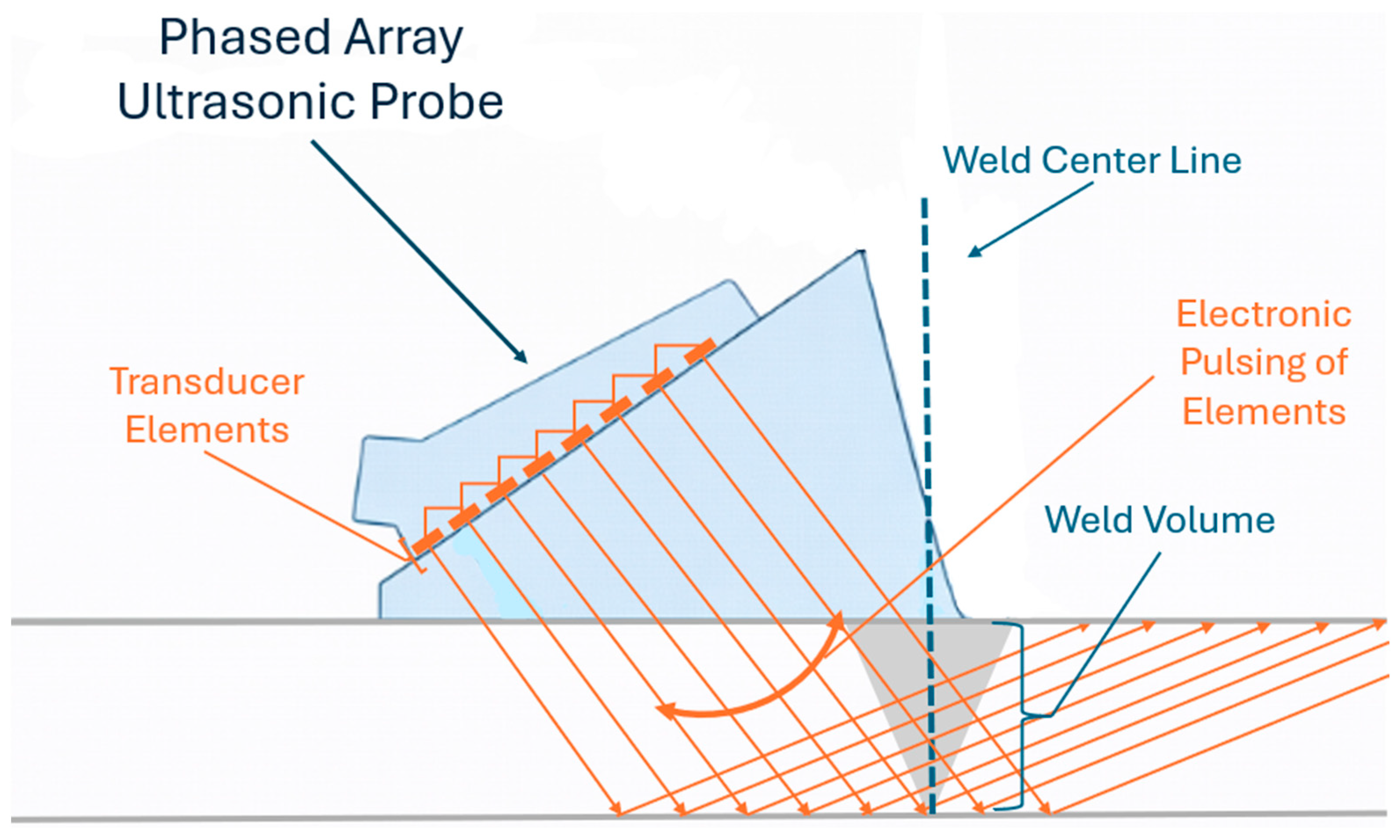
The concept of focal laws is central to PAUT operation. By adjusting delay patterns across the array elements, the beam can be dynamically focused at the specific depths or swept through a range of refracted angles in a sectorial scan, as observed in Figure 5. This capability allows inspectors to interrogate weld fusion zones, roots, and adjacent heat-affected regions with improved control over direction [64,65,68]. Unlike conventional UT, which requires discrete wedge angles to change beam direction, PAUT can perform multi-angle interrogation in a continuous manner. This reduces scanning time and improves the probability of intercepting defects that are unfavorably oriented relative to a single beam angle [69]. The result is more comprehensive volumetric coverage of welded joints.
Another defining characteristic of PAUT is its enhanced data acquisition and digital storage capability. Multi-element scanning produces large datasets that can be visualized in real time and stored for later review [51,63]. This facilitates improved documentation, traceability, and quality assurance compared to conventional A-scan-based methods. In infrastructure applications, where inspection documentation may influence long-term maintenance decisions, such traceability is valuable. The digital nature of PAUT also enables more advanced post-processing techniques, setting the stage for further innovation in ultrasonic inspection [63].

4.2. PAUT Advantages

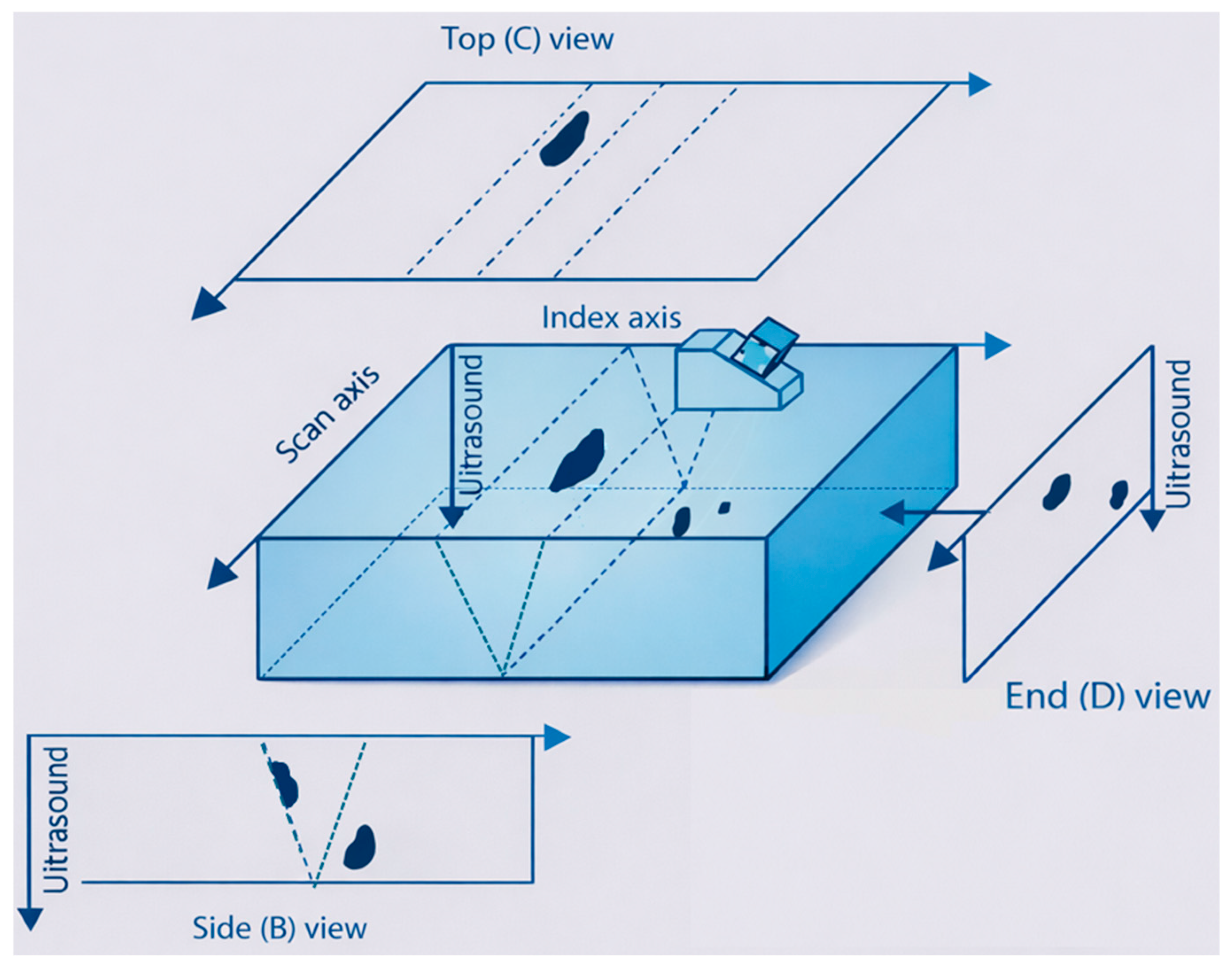
One of the primary advantages of PAUT is its ability to generate two- and three-dimensional representations of the inspected volume. Through S-scans, B-scans, and C-scans, visualized in Figure 6, ultrasonic data can be visualized spatially rather than interpreted solely as amplitude–time plots [51,67,70]. This improved visualization enhances interpretability and reduces ambiguity in defect characterization. Inspectors are better able to assess defect morphology, orientation, and spatial location relative to the weld geometry. In complex welded joints, this contextual understanding significantly improves decision-making confidence.
Multi-angle interrogation further improves detection probability, particularly for planar and crack-like discontinuities whose ultrasonic response depends strongly on beam orientation. Conventional single-angle UT may fail to adequately detect a defect that is poorly oriented relative to the beam path. In contrast, sectorial scanning displayed in Figure 5 allows PAUT to interrogate a weld across a range of refracted angles in a single pass. This improves sensitivity to a wider variety of defect orientations and reduces the likelihood of missed indications [67]. For nonredundant steel tension members or fracture-critical welds in infrastructure, such improvements in detection reliability are particularly valuable.
Beyond detection, PAUT offers enhanced defect sizing capability. Improved signal-to-noise ratio and depth perception have been demonstrated in comparative evaluation against single-element UT [40]. The comparison between conventional UT and PAUT is further outlined in Table 3. More consistent focusing across the weld region enables improved characterization of defect extent and location. In infrastructure contexts, where acceptance decisions depend not only on detection but also on accurate sizing, these advantages are significant [25]. Collectively, the improved coverage, interpretability, and sizing performance of PAUT have contributed to its growing adoption in structural steel inspection [71].
From an engineering perspective, the principal benefit of PAUT lies in reducing inspection uncertainty rather than merely increasing sensitivity. Multi-angle interrogation improves the likelihood that crack-like defects are detected at a favorable orientation, thereby stabilizing detection probability across inspectors and inspection conditions. Improved visualization also allows interpretation to rely less on amplitude estimation and more on geometric context. This shift reduces variability between operators and improves confidence in acceptance decisions. Consequently, the value of PAUT in infrastructure inspection is best understood as improved reliability of assessment rather than simply improved detectability.
Despite these advantages, PAUT also presents several practical limitations that must be considered during inspection planning. Interpretation of sectorial scan data can produce false indications when geometric reflections, weld features, mode conversions, or inspector probe positioning generate responses that resemble defect signals [43]. Additionally, although multi-angle interrogation improves detection probability, defects that are poorly oriented to the angle of incidence may still produce weak responses and remain difficult to detect [47]. Beam spread and focal law limitations can also reduce resolution at greater depths, particularly in thick sections where accurate focusing becomes more challenging. Reliable inspection further depends on consistent coupling positions and probe positioning, both of which may be difficult to maintain in field environments with rough surfaces or restricted access [42,65,66]. Consequently, while PAUT significantly improves inspection coverage compared to conventional UT, effective implementation still requires careful procedure qualification, skilled interpretation, and consideration of weld geometry and inspection conditions.

4.3. Advanced Imaging

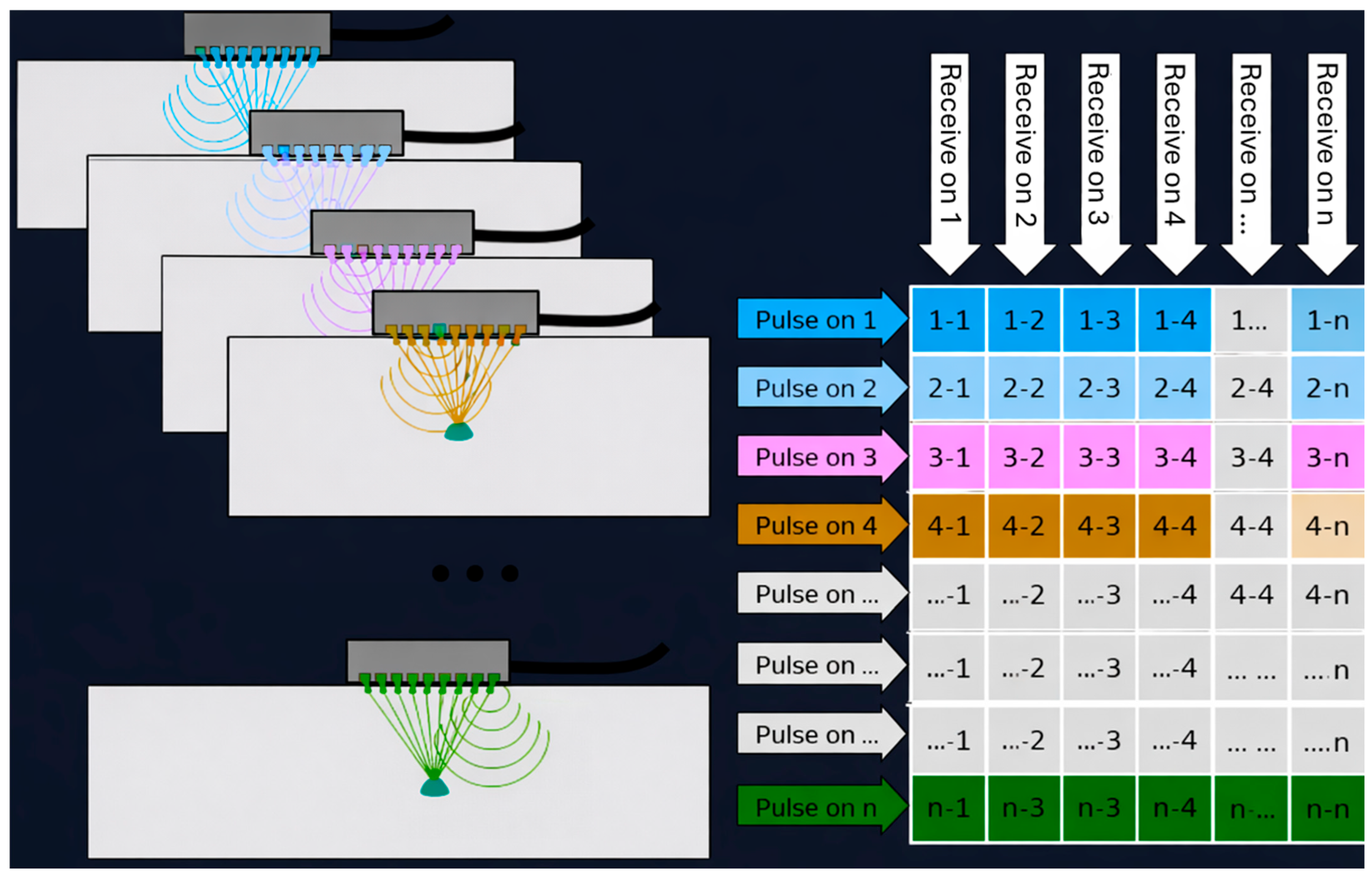
While standard PAUT represents a substantial advancement over conventional UT, further evolution has led to advanced imaging modalities such as Full Matrix Capture (FMC) and the Total Focusing Method (TFM). Conventional PAUT forms images through electronic beam steering, dynamic focusing, and manual positioning throughout the inspection process, where many elements transmit together, each with a different time delay to constructively interfere and produce a steered and focused beam at a specific angle [42,45,65]. By contrast, with synthetic aperture techniques such as TFM, each array element transmits individually while all other elements receive. The image is formed after acquisition using reconstruction algorithms in near real time, synthetically creating images through computation [77,78].
FMC, utilized in TFM and visualized in Figure 7, involves recording all transmit–receive element combinations within an array, effectively capturing the complete set of wave interactions within the inspected region [79]. This approach generates a comprehensive dataset that preserves detailed information about wave propagation paths. Unlike conventional focal laws that are predefined during acquisition, FMC allows flexile post-processing to reconstruct images with various focusing strategies. The result is a shift from physical focusing, beam-based inspection toward data-centric imaging.
The Total Focusing Method builds upon FMC data by synthetically focusing ultrasonic energy at every point within the region of interest. Using computational algorithms, TFM reconstructs wave paths from each transmit–receive pair to generate highly resolved images [74,80,81]. This synthetic focusing significantly improves spatial resolution compared to conventional PAUT imaging. Small, closely spaced, or geometrically complex discontinuities can be resolved with greater clarity. For welded steel infrastructure, where defect morphology and orientation directly influence structural performance, such enhanced imaging is particularly relevant.
However, advanced imaging modalities introduce increased data volume and computational demands. FMC datasets can be significantly larger than conventional PAUT data because signals from every transmit–receive element pair must be recorded, resulting in a large number of A-scans per inspection position [79]. This increase in data density substantially raises storage requirements and can lead to longer processing times when reconstructing TFM images. In field applications, balancing inspection speed with computational requirements becomes an important consideration. Data density may reduce scanning speed depending on the inspection geometry, requiring inspectors to balance acquisition rate with data transfer and processing capabilities. Additionally, real-time implementation often requires high-performance computing hardware, such as multi-core processors or GPUs, which may not always be practical in field environments [78]. Despite these challenges, advances in computing hardware and signal processing algorithms are steadily improving field implementation feasibility [74,80]. As computational efficiency increases, advanced imaging techniques are likely to play an expanding role in infrastructure inspection.
Despite superior imaging capability, advanced modalities such as FMC and TFM are not universally necessary for all weld inspections. Table 4 summarizes typical inspection scenarios and highlights situations where the increased spatial resolution of TFM provides a clear advantage over conventional PAUT. In particular, TFM has demonstrated improved capability for the detection and characterization of planar defects such as lack-of-fusion and fatigue cracks, because the reconstruction process enhances diffraction signals from crack tips while reducing dependence on amplitude-based interpretation. Several studies have reported improved flaw sizing accuracy using TFM compared with conventional beam steering approaches in PAUT, particularly for complex weld geometries and closely spaced reflectors [46,73,74,81,82]. TFM has also proven valuable in failure investigations and research applications where high-resolution reflectivity maps allow detailed analysis of flaw morphology and enable more reliable comparison between repeated inspections [83]. However, these advantages must be balanced against the increased data acquisition and processing requirements discussed previously.
While FMC and TFM are not universally required for all weld inspections, FMC and TFM’s greatest value arises in situations where defect morphology and orientation strongly influence structural performance, such as nonredundant steel tension members, or fracture-critical members of fatigue-sensitive regions, whose failure may cause a portion of or total structural collapse [77]. For the inspection of these special cases, additional inspection of the base metal occurs to ensure metal fatigue and defects are not overlooked. In this instance, the application of FMC and TFM serves as a necessary action to prevent structural failure [24]. The practical adoption of advanced imaging therefore depends on balancing resolution benefits against structural need, acquisition time, and computational effort. In this sense, FMC and TFM should be viewed as targeted tools for reducing decision uncertainty rather than universal replacements for standard phased array inspection.

5. Implementation, Standards, and Field Use

The successful implementation of ultrasonic inspection techniques in welded steel infrastructure depends on integration within established codes and standards [71]. Conventional UT procedures are well defined in structural welding specifications, providing clear guidance on calibration, acceptance criteria, and inspection methodology [31]. The incorporation of phased array annexes into welding standards reflects growing institutional recognition of PAUT capabilities [25,71]. These developments, summarized in Table 5, provide a regulatory framework for adopting advanced ultrasonic techniques. Although ultrasonic inspection standards such as AWS D1.1-D1.5 and related structural inspection codes provide well-established acceptance criteria for conventional UT and PAUT, these criteria are largely based on amplitude-based evaluation methods [29,30,31]. Advanced imaging techniques such as FMC/TFM produce high-resolution reflectivity maps rather than single amplitude responses, which can make direct application of traditional amplitude-based acceptance criteria challenging. Ongoing research and industry working groups are exploring how imaging-based metrics and probability of detection studies could support future codes provisions tailored to advanced imaging methods [25,46]. Standardization is therefore essential for ensuring consistent application across infrastructure systems.
Selection of an inspection methodology in practice is rarely based on detection capability alone. Agencies must balance reliability, cost, inspection time, qualification requirements, and data interpretation complexity. While advanced techniques provide improved information, they also introduce additional training and procedural demands [88]. The appropriate method therefore depends on the structural criticality of the component and the consequence of failure. For example, in the instance of nonredundant steel tension members or fracture-critical regions, additional inspection services are required for the base metal, providing an instance where advanced TFM imaging is necessary to avoid complete structural failure [86]. Additionally, advanced imaging such as TFM may be required when the flaw type and location are unknown, providing a 28.2% increase in POD over traditional PAUT and sub 2 mm accuracy for small defects [46,73]. Effective implementation therefore requires matching inspection resolution to engineering decision requirements rather than universally applying the most advanced available techniques.
Field implementation of PAUT and advanced imaging modalities presents additional challenges beyond regulatory acceptance. Welded infrastructure components often involve restricted access, irregular surfaces, coatings, and environmental exposure that complicate inspection. While PAUT is more adaptable to irregular geometries compared to traditional UT, it is still sensitive to large environmental vibrations that occur on live bridge inspection sites [42]. With this, equipment portability, power supply, and probe coupling conditions must be addressed during deployment. Inspector training and certification are therefore critical to ensure consistent application and interpretation of advanced ultrasonic techniques. Digital storage of PAUT datasets enables retrospective review and supports long-term asset management strategies. Infrastructure owners may use archived inspection data to track defect evolution over time [89]. This capability aligns with broader trends toward data-driven infrastructure management [90]. Effective implementation therefore requires not only technological capability but also procedural rigor and integration within asset management systems. Without this, proper training, and qualification of inspectors, the advantages of PAUT and advanced imaging may not be fully realized.

6. Automation, AI, and Future Directions

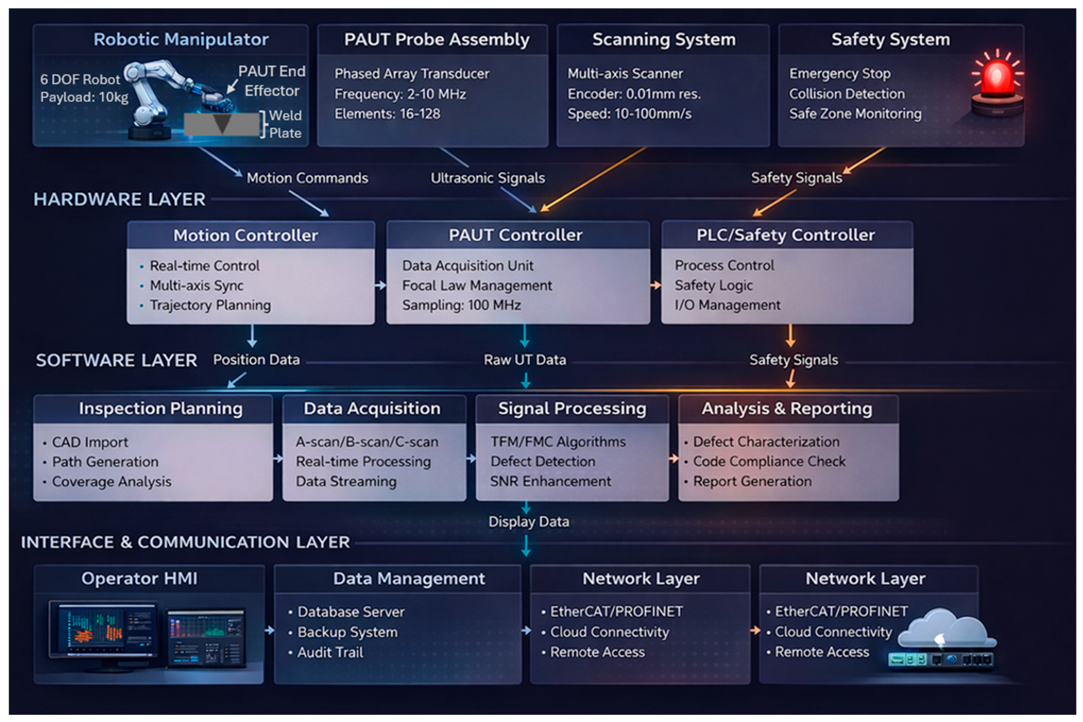
Automation and intelligent interpretation are being pursued primarily to address repeatability rather than replace inspectors. A framework for this implementation is displayed in Figure 8, which illustrates a digital inspection workflow combining automated scanning, ultrasonic data acquisition, algorithm-assisted interpretation, and data integration within asset management systems, summarized across representative studies and further expanded on here. Manual ultrasonic inspection inherently introduces variability in probe positioning, coupling, and interpretation, particularly across large infrastructure systems inspected over long service lives [90,91,92]. Mechanized scanning and algorithm-assisted evaluation aim to standardize data acquisition and stabilize interpretation outcomes [59,93]. The goal is not to eliminate human expertise but to ensure consistent measurements across time, inspectors, and structures.
Figure 8 conceptually represents a closed digital inspection loop. Automated scanning systems collect repeatable ultrasonic measurements while minimizing variations in probe placement and scanning velocity [59,87,93]. Machine learning-based analysis tools can subsequently assist inspectors by identifying potential indications, classifying defect types, and supporting flaw sizing [94]. Recent studies have demonstrated that deep learning models can successfully classify ultrasonic defect types from PAUT and TFM imaging datasets [95]. For example, CNN-based classifiers trained on labeled ultrasonic weld datasets have achieved classification accuracies exceeding 99% for common weld discontinuities, including cracks, porosity, and lack-of-fusion defects [81]. After analysis, the processed inspection results can be stored within digital infrastructure management systems or digital twin models, enabling comparison between inspection campaigns and supporting long-term structural modeling [63,77,96].
The evolution of ultrasonic inspection is increasingly linked with automation and intelligent data analysis. Automated scanning systems can improve repeatability by reducing variability associated with manual probe manipulation [59]. Mechanized or robotic scanning platforms allow consistent probe positioning and controlled movement across large welds [69], reducing the occurrence of false indications due to probe pressure or alignment variations [83]. For infrastructure applications involving difficult access or hazardous environments, automation can enhance safety and reliability [87,97]. These developments represent an important step toward standardization and repeatable inspection procedures.
In parallel, advances in artificial intelligence (AI) and machine learning (ML) offer new opportunities for ultrasonic data interpretation. A primary limitation of PAUT interpretation is the reliance on operator experience to distinguish true defects from geometric reflections or noise artifacts. Machine learning algorithms have been explored as a means of addressing this challenge by identifying patterns in ultrasonic datasets associated with specific defect types and successfully avoiding application errors such as signal dropout or environmental noise [83,98]. In particular, convolutional neural networks (CNNs) have demonstrated promising performance in classifying ultrasonic images derived from B-scan, C-scan, and TFM reconstructions. For example, CNN-based models trained on B-scan, C-scan, and TFM ultrasonic images have demonstrated strong performance in distinguishing crack-like defects from geometric reflections, reducing the reliance on manual interpretation [76]. These models can automatically extract spatial features related to crack morphology, porosity distributions, or lack-of-fusion indications, enabling more consistent defect classification [99,100]. Such approaches aim to reduce subjectivity inherent in manual amplitude-based interpretation. By leveraging large datasets, AI-assisted methods may improve consistency and efficiency in inspection workflows [54,63,94,100,101]. However, robust validation and careful training data selection are essential to ensure reliability and avoid overfitting.
Beyond classification, machine learning techniques are also being investigated for automated flaw sizing and localization. Algorithms capable of analyzing diffraction signals and reflectivity patterns may help improve the accuracy and repeatability of defect sizing compared with conventional amplitude-based interpretation methods [47,102]. Such approaches are particularly relevant for advanced imaging techniques such as FMC/TFM, where large datasets provide rich spatial information that can be leveraged by data-driven algorithms. In addition, data augmentation strategies are increasingly explored to address the limited availability of labeled ultrasonic datasets [103]. Generative adversarial networks (GANs), for example, have been proposed as a means of generating synthetic ultrasonic images to expand training datasets and improve model robustness when real defect data is limited [104,105].
Despite promising results, several challenges remain before AI-assisted ultrasonic inspection can be widely implemented within infrastructure applications. Machine learning models require large, high-quality labeled datasets, which can be difficult to obtain for rare defect types or safety-critical infrastructure components [94,95]. Model validation and reliability assessment are also critical concerns, particularly when inspection results may influence structural integrity decisions. In this context, explainable artificial intelligence (XAI) approaches are being investigated to provide greater transparency regarding the features used by machine learning models when identifying defects [106]. Ensuring that automated analysis tools produce interpretable and traceable results will be essential for regulatory acceptance and industry adoption.
Looking forward, integration of advanced ultrasonics with automation, digital data management, and intelligent interpretation frameworks suggests a broader transformation in infrastructure monitoring. Inspection data may increasingly be integrated within digital asset management platforms or digital twin models [107,108]. Such integration could enable predictive maintenance strategies informed by real inspection data over the service life of a structure. Continued research, validation, and standardization will be necessary to ensure these technologies are deployed safely and effectively. The convergence of advanced imaging, automation, and AI represents a promising direction for the future of weld inspection.

7. Conclusions

Ultrasonic testing has long served as a cornerstone of weld inspection in steel infrastructure due to its ability to detect internal discontinuities without damaging the structure. Conventional UT remains widely used and codified within established standards, providing a practical foundation for nondestructive evaluation. However, inherent limitations related to beam control, imaging capability, and interpretive subjectivity have driven the development of advanced techniques. Phased Array Ultrasonic Testing (PAUT) has addressed many of these limitations by enabling electronic beam steering, improved coverage, and enhanced visualization. These advancements have significantly strengthened inspection reliability in complex welded systems.
Advanced modalities such as FMC and TFM further extend ultrasonic capabilities by providing high-resolution, data-centric imaging. Although computational demands remain a practical consideration, continued improvements in processing power are expanding their feasibility for field deployment. Implementation within infrastructure contexts requires careful integration with standards, training, and asset management systems. As ultrasonic technologies continue to evolve, their role in supporting condition-based maintenance and risk-informed decision-making will likely expand. The future of welded steel inspection lies in the continued refinement and integration of advanced ultrasonic methods within intelligent infrastructure management frameworks.
Future progress in ultrasonic inspection of welded steel infrastructure will likely depend less on increasing sensitivity and more on improving interpretability and decision relevance. As inspection technologies advance, the primary challenge becomes translating measurement data into reliable engineering actions. Methods that reduce uncertainty in sizing, orientation assessment, and defect significance will have the greatest practical impact, particularly as the use of automation and AI continues to grow. Integration of advanced ultrasonics with structural assessment frameworks, therefore, represents a critical research direction. Ultimately, the value of nondestructive evaluation lies in enabling confident infrastructure decisions rather than simply detecting discontinuities.

Funding

This research received no external funding.

Data Availability Statement

No new data were created or analyzed in this study. Data sharing is not applicable to this article.

Acknowledgments

The authors would like to thank Georgia Southern University’s Allen E. Paulson College of Engineering and Computing as well as the Jack N. Averitt College of Graduate Studies for their support throughout the duration of this project. During the preparation of this manuscript, the authors used Figma Make (Figma Inc.,Figma.com web-based tool, accessed on the 17 February 2026) for purposes of assistance in drafting conceptual figures. The authors have reviewed and edited the output and take full responsibility for the content of this publication.

Conflicts of Interest

The authors declare no conflict of interest.

References

  1. Lin, W.; Teurhiko, Y. Bridge Engineering: Classifications, Design Loading, and Analysis Methods; Elsevier: Amsterdam, The Netherlands, 2017; ISBN 10.0128044322. [Google Scholar]
  2. Freyermuth, C. Building Better Bridges: Concrete vs. Steel. Civ. Eng.-ASCE 1992, 62, 66–71. [Google Scholar]
  3. FHWA. Bridge Inspector’s Reference Manual (BIRM). 2020. Available online: https://www.fhwa.dot.gov/bridge/inspection/ (accessed on 2 February 2026).
  4. FHWA. Specifications for the National Bridge Inventory; FHWA: Washington, DC, USA, 2022. [Google Scholar]
  5. FHWA. Bridge Welding Reference Manual. 2019. Available online: http://www.ntis.gov (accessed on 2 February 2026).
  6. ASCE Infrastructure Report Card. 2021. Available online: www.infrastructurereportcard.org (accessed on 2 February 2026).
  7. FHWA. Non-Destructive Testing of Fracture Critical Members Fabricated from AASHTO M244 Grade 100 (ASTM A514/A517) Steel; FHWA: Washington, DC, USA, 2021. [Google Scholar]
  8. Lee, S.; Kalos, N.; Shin, D.H. Non-destructive testing methods in the U.S. for bridge inspection and maintenance. KSCE J. Civ. Eng. 2014, 18, 1322–1331. [Google Scholar] [CrossRef]
  9. Spears, M.; Hedjazi, S.; Taheri, H. Ground penetrating radar applications and implementations in civil construction. J. Struct. Integr. Maint. 2023, 8, 36–49. [Google Scholar] [CrossRef]
  10. Linton, V.M.; Ripley, M.I. Influence of time on residual stresses in friction stir welds in age hardenable 7xxx aluminum alloys. Acta Mater. 2008, 56, 4319–4327. [Google Scholar] [CrossRef]
  11. Javadi, Y.; Sweeney, N.E.; Mohseni, E.; MacLeod, C.N.; Lines, D.; Vasilev, M.; Qiu, Z.; Mineo, C.; Pierce, S.G.; Gachagan, A. Investigating the effect of residual stress on hydrogen cracking in multi-pass robotic welding through process compatible non-destructive testing. J. Manuf. Process. 2021, 63, 80–87. [Google Scholar] [CrossRef]
  12. Harara, W.; Altahan, A. Attempt Towards the Replacement of Radiography with Phased Array Ultrasonic Testing of Steel Plate Welded Joints Performed on Bridges and Other Applications. Russ. J. Nondestruct. Test. 2018, 54, 335–344. [Google Scholar] [CrossRef]
  13. Haghani, R.; Al-Emrani, M.; Heshmati, M. Fatigue-prone details in steel bridges. Buildings 2012, 2, 456–476. [Google Scholar] [CrossRef]
  14. Fuštar, B.; Lukačević, I.; Dujmović, D. Review of Fatigue Assessment Methods for Welded Steel Structures. Adv. Civ. Eng. 2018, 2018, 3597356. [Google Scholar] [CrossRef]
  15. Andersson, M.; Danielsson, P.O. A simplified fracture mechanics method for fatigue life analysis of weld roots. Procedia Struct. Integr. 2023, 57, 307–315. [Google Scholar] [CrossRef]
  16. Kanvinde, A.M.; Deierlein, G.G. Cyclic Void Growth Model to Assess Ductile Fracture Initiation in Structural Steels due to Ultra Low Cycle Fatigue. J. Eng. Mech. 2007, 701–712. [Google Scholar] [CrossRef]
  17. Wang, C.; Zhu, T.; Yang, B.; Xiao, S.; Yang, G. A study of fatigue surface crack propagation paths of aluminum alloy butt welds using a Phased-Array Total-Focus imaging technique. Theor. Appl. Fract. Mech. 2024, 133, 104572. [Google Scholar] [CrossRef]
  18. Taheri, H.; Jones, C.; Taheri, M. Assessment and detection of stress corrosion cracking by advanced eddy current array nondestructive testing and material characterization. J. Nat. Gas Sci. Eng. 2022, 102, 104568. [Google Scholar] [CrossRef]
  19. Khedmatgozar Dolati, S.S.; Caluk, N.; Mehrabi, A.; Khedmatgozar Dolati, S.S. Non-destructive testing applications for steel bridges. Appl. Sci. 2021, 11, 9757. [Google Scholar] [CrossRef]
  20. Kanvinde, A. Predicting Fracture in Civil Engineering Steel Structures: State of the Art. J. Struct. Eng. 2017, 143. [Google Scholar] [CrossRef]
  21. Htut, Z.L.; Osawa, N.; Tanaka, S.; Toyosada, M. Efficient technique for evaluation of three-dimensional elastic–plastic fracture mechanics parameters based on equivalent distributed stress concept. Theor. Appl. Fract. Mech. 2024, 131, 104357. [Google Scholar] [CrossRef]
  22. Mosavi, A.; Yuan, H.; Carter, M. Reclassifying Fracture Critical Members (Non-Redundant Steel Tension Members) to System Redundant Members in a Steel Arch Bridge. Transp. Res. Rec. J. Transp. Res. Board 2022, 2679, 138–155. [Google Scholar] [CrossRef]
  23. Torti, A.; Arena, M.; Azzone, G.; Secchi, P.; Vantini, S. Bridge closure in the road network of Lombardy: A spatio-temporal analysis of the socio-economic impacts. Stat. Methods Appt. 2022, 31, 901–923. [Google Scholar] [CrossRef]
  24. Parr, M.J.; Connor, R.J.; Bowman, M. Proposed Method for Determining the Interval for Hands-on Inspection of Steel Bridges with Fracture Critical Members. J. Bridge Eng. 2009, 15, 352–363. [Google Scholar] [CrossRef]
  25. Azari, H.; Kok, R. Implementation of American Association of State Highway and Transportation Officials/American Welding Society D1.5 Phased Array Ultrasonic Weld Inspection Programs. Transp. Res. Rec. 2022, 2676, 486–494. [Google Scholar] [CrossRef]
  26. Gobbato, M.; Conte, J.P.; Kosmatka, J.B. Statistical performance assessment of an NDE-based SHM-DP methodology for the remaining fatigue life prediction of monitored structural components and systems. Proc. IEEE 2016, 104, 1575–1588. [Google Scholar] [CrossRef]
  27. ASTM E164-19; Standard Practice for Contact Ultrasonic Testing of Weldments. ASTM International: West Conshohocken, PA, USA, 2019. [CrossRef]
  28. Ali, M.G.S.; Elsayed, N.Z.; Eid, A.M. Ultrasonic Attenuation and Velocity in Steel Standard Reference Blocks. Available online: https://www.researchgate.net/publication/256293732 (accessed on 2 February 2026).
  29. Duke, S.M. Comparative Testing of Radiographic Testing, Ultrasonic Testing and Phased Array Advanced Ultrasonic Testing Non Destructive Testing Techniques in Accordance with the AWS D1.5 Bridge Welding Code; The Florida Department of Transportation Research Center: Tallahassee, FL, USA, 2014. [Google Scholar]
  30. AWS D1.1 D1.1M-2010; Structural Welding Code—Steel. American Welding Society: Doral, FL, USA, 2020.
  31. AASHTO/AWS D1.5M/D1.5:2020; Bridge Welding Code. American Association of State Highway and Transportation Officials: Washington, DC, USA; American Welding Society: Doral, FL, USA, 2020.
  32. Fan, J.; Dong, L.; Sun, D.; Ma, C.; Zhang, Z.; Wei, B.; Wang, Q.; Liu, L. Microstructure and gaseous hydrogen embrittlement of gas metal arc welding, cold metal transfer, and flux-cored arc welding weldments of X52 steel. Corros. Sci. 2026, 258, 113442. [Google Scholar] [CrossRef]
  33. Rizvi, S.A.; Ahamad, M. Effect of Heat Input on the Microstructure and Mechanical Properties of a Welded Joint—A Review. 2018. Available online: http://www.ripublication.com (accessed on 2 February 2026).
  34. Phetlam, P.; Uthaisangsuk, V. Microstructure based flow stress modeling for quenched and tempered low alloy steel. Mater. Des. 2015, 82, 189–199. [Google Scholar] [CrossRef]
  35. Di, X.; Ji, S.; Cheng, F.; Wang, D.; Cao, J. Effect of cooling rate on microstructure, inclusions and mechanical properties of weld metal in simulated local dry underwater welding. Mater. Des. 2015, 88, 505–513. [Google Scholar] [CrossRef]
  36. Li, D.; Yang, X.; Cui, L.; He, F.; Shen, H. Effect of welding parameters on microstructure and mechanical properties of AA6061-T6 butt welded joints by stationary shoulder friction stir welding. Mater. Des. 2014, 64, 251–260. [Google Scholar] [CrossRef]
  37. Talabi, S.I.; Owolabi, O.B.; Adebisi, J.A.; Yahaya, T. Effect of welding variables on mechanical properties of low carbon steel welded joint. Adv. Prod. Eng. Manag. 2014, 9, 181–186. [Google Scholar] [CrossRef]
  38. Ulbrich, D.; Psuj, G.; Wypych, A.; Bartkowski, D.; Bartkowska, A.; Stachowiak, A.; Kowalczyk, J. Inspection of Spot Welded Joints with the Use of the Ultrasonic Surface Wave. Materials 2023, 16, 7029. [Google Scholar] [CrossRef]
  39. ASTM A709/A709M-21; Standard Specification for Structural Steel for Bridges. AASHTO: Washington, DC, USA, 2023.
  40. Ji, Z.; Xu, D.; Wang, H.; Chen, J.; Fu, Y. Recent Advances in Non-Destructive Testing Technology for Coated Steel Structure Welds. Sensors 2025, 25, 6923. [Google Scholar] [CrossRef]
  41. Guo, W.; Zhao, X.; Zhao, Y.; Liu, Y.; Li, H.; Han, B. Research on optimal heat input parameter for TIG welding of thin plate 5083 aluminum alloy. Sci. Rep. 2025, 15, 15593. [Google Scholar] [CrossRef]
  42. Schultz, M.T.; Campbell, L.E.; Bell, R.D.; Sauser, P.W. A Study of Phased-Array Ultrasonic Testing (PAUT) for Detecting, Sizing, and Characterizing Flaws in the Welds of Existing Hydraulic Steel Structures (HSS). 2024. U.S. Army Engineer Research & Development Center. Available online: http://dx.doi.org/10.21079/11681/48750 (accessed on 2 February 2026).
  43. Williams, C.; Lappin, E.; Taheri, H. Assessment of Process Induced Welding Flaws in Structural Steel Members Using Phased Array Ultrasonic Nondestructive Testing. In Proceedings of the ASME 2024 International Mechanical Engineering Congress and Exposition, Portland, OR, USA, 17–21 November 2024. [Google Scholar] [CrossRef]
  44. Ultrasonic Flaw Detection Tutorial 2.5 Wave Front Dynamics Wave Front Formation. Available online: https://www.olympus-ims.com/en/ndt-tutorials/flaw-detection/wave-front/ (accessed on 16 January 2026).
  45. Ye, J.; Kim, H.J.; Song, S.J.; Kang, S.S.; Kim, K.; Song, M.H. Model-based simulation of focused beam fields produced by a phased array ultrasonic transducer in dissimilar metal welds. NDT E Int. 2011, 44, 290–296. [Google Scholar] [CrossRef]
  46. Irtiza, C.M.; Silwal, B.; Taheri, H. Ultrasonic Detectability of Planar and Volumetric Weld Defects: A Simulation-Based Signal-Response POD Study. NDT 2026, 4, 9. [Google Scholar] [CrossRef]
  47. Wilcox, P.D.; Holmes, C.; Drinkwater, B.W. Advanced reflector characterization with ultrasonic phased arrays in NDE applications. IEEE Trans. Ultrason. Ferroelectr. Freq. Control 2007, 54, 1541–1550. [Google Scholar] [CrossRef]
  48. Wang, Y.; Liu, N.; Gong, Y.; Zhu, X.; Li, Z.; Long, Z.; Teng, J.; Chen, J. Three-dimensional stress measurement for structural steel plates using ultrasonic T-waves and P-waves. Measurement 2022, 190, 110310. [Google Scholar] [CrossRef]
  49. Marcantonio, V.; Monarca, D.; Colantoni, A.; Cecchini, M. Ultrasonic waves for materials evaluation in fatigue, thermal and corrosion damage: A review. Mech. Syst. Signal Process 2019, 120, 32–42. [Google Scholar] [CrossRef]
  50. Ensminger, D.; Bond, J.L. Ultrasonics Fundamentals, Technologies, and Applications, 4th ed.; CRC Press: Boca Raton, FL, USA, 2025. [Google Scholar]
  51. Taheri, H.; Hassen, A.A. Nondestructive ultrasonic inspection of composite materials: A comparative advantage of phased array ultrasonic. Appl. Sci. 2019, 9, 1628. [Google Scholar] [CrossRef]
  52. Taheri, H.; Delfanian, F.; Du, J. Acoustic Emission and Ultrasound Phased Array Technique for Composite Material Evaluation. In Proceedings of the ASME 2013 International Mechanical Engineering Congress and Exposition, San Diego, CA, USA, 15–21, November 2013. [Google Scholar] [CrossRef]
  53. Wang, W.; Xu, C.; Zhang, Y.; Zhou, Y.; Meng, S.; Deng, Y. An improved ultrasonic method for plane stress measurement using critically refracted longitudinal waves. NDT E Int. 2018, 99, 117–122. [Google Scholar] [CrossRef]
  54. Yang, Z.; Yang, H.; Tian, T.; Deng, D.; Hu, M.; Ma, J.; Gao, D.; Zhang, J.; Ma, S.; Yang, L.; et al. A review in guided-ultrasonic-wave-based structural health monitoring: From fundamental theory to machine learning techniques. Ultrasonics 2023, 133, 107014. [Google Scholar] [CrossRef] [PubMed]
  55. Filipík, A.; Jan, J.; Peterlík, I. Time-of-Flight Based Calibration of an Ultrasonic Computed Tomography System. Radioengineering 2012, 21, 533–544. [Google Scholar]
  56. Chivers, R.C. Fundamentals of Ultrasonic Propagation; Springer: London, UK, 1991; ISBN 978-1-4471-1883-1. [Google Scholar]
  57. ASTM E587-15(2020); Standard Practice for Ultrasonic Angle-Beam Contact Testing. ASTM International: West Conshohocken, PA, USA, 2020. [CrossRef]
  58. Hossain, M.S.; Krenek, R.; Taheri, H.; Dababeneh, H. Ultrasonic Phased Array Technique for Defect Detection and Sizing in Heavy-Walled Cast Components. In Proceedings of the International Mechanical Engineering Congress and Exposition, Virtual, Online, 16–19 November 2020. [Google Scholar] [CrossRef]
  59. Lappin, E.; Oubre, J.; Gurau, V.; Taheri, H. Automated Robotic and AI-Driven Nondestructive Inspection for Enhanced Welding Flaw Detection. In Proceedings of the 2025 6th International Conference on Artificial Intelligence, Robotics and Control (AIRC), Savannah, GA, USA, 7–9 May 2025. [Google Scholar]
  60. Kinra, V.K.; Zhu, C. Time-Domain Ultrasonic NDE of the Wave Velocity of a Sub-Half-Wavelength Elastic Layer. 1993. Available online: www.astm.org (accessed on 16 February 2026).
  61. Cho, Y. Estimation of Ultrasonic Guided Wave Mode Conversion in a Plate with Thickness Variation. IEEE Trans. Ultrason. Ferroelectr. Freq. Control. 2000, 47, 591–603. [Google Scholar] [CrossRef] [PubMed]
  62. Vavilov, V.; Chulkov, A.; Dubinskii, S.; Burleigh, D.; Shpilnoi, V.; Derusova, D.; Zhvyrblia, V. Nondestructive testing of composite T-Joints by TNDT and other methods. Polym. Test. 2021, 94, 107012. [Google Scholar] [CrossRef]
  63. Lappin, E.; Taheri, H. AI Driven Interpretation of PAUT Data for AWS-Compliant Weld Flaw Assessment in Structural Steel Bridge Components. In Proceedings of the Transportation Research Board Annual Meeting, Washington, DC, USA, 11–15 January 2026. [Google Scholar]
  64. Luo, Z.-B.; Li, F.-L.; Cao, H.-Q.; Jin, S.-J.; Lin, L. Focal Law Optimization and Acoustic Field Simulation of PAUT on CFRP Radii. In Proceedings of the 2018 IEEE Far East NDT New Technology & Application Forum (FENDT), Xiamen, China, 6–8 July 2018; pp. 122–126. [Google Scholar] [CrossRef]
  65. Anandamurugan, S. Manual Phased Array Ultrasonic Technique for Weld Application. Available online: https://www.ndt.net/?id=9863 (accessed on 16 January 2026).
  66. Liu, W.; Wen, Z.; Wang, J.; Wang, S.; Wang, H.; Zhang, W.; Huang, S.; Hong, J. Experimental Study on Lateral Resolution of Phased Array Ultrasonic Testing of Irregular Structure Weld Defects. Shock Vib. 2022, 2022, 1427417. [Google Scholar] [CrossRef]
  67. Taheri, H.; Delfanin, F.; Du, J. Conventional and Phased Array Ultrasonic Testing for Composite Materials. In Proceedings of the ASNT 23rd Research Symposium, Minneapolis, MN, USA, 24–27 March 2014; pp. 114–148. [Google Scholar]
  68. Richard, D.; Zottig, F.; Maes, G. On the Use of Advanced Focusing Techniques for Enhanced PA UT Inspection Capability. Available online: http://www.ndt.net/?id=22764 (accessed on 16 January 2026).
  69. Lappin, E.; Oubre, J.; Taheri, H. Enhancing PAUT Inspection with Machine Vision and AI for Intelligent Structural Integrity Assessment. In Proceedings of the 2025 International Mechanical Engineering Congress and Exposition, Memphis, TN, USA, 16–20 November 2025. [Google Scholar] [CrossRef]
  70. Taheri, H.; Du, J.; Delfanian, F. Experimental Observation of Phased Array Guided Wave Application in Composite Materials. Mater. Eval. 2017, 75, 1308–1316. [Google Scholar]
  71. FHWA-HRT-24-010; Implementation of Phased Array Ultrasonic Testing (PAUT) For Bridge Welds. FHWA: Washington, DC, USA, 2024. Available online: https://highways.dot.gov/sites/fhwa.dot.gov/files/FHWA-HRT-24-010.pdf (accessed on 16 January 2026).
  72. Mielentz, F. Phased Arrays for Ultrasonic Investigations in Concrete Components. J. Nondestruct. Eval. 2008, 27, 23–33. [Google Scholar] [CrossRef]
  73. Irtiza, C.M.; Silwal, B.; Kardel, K.; Taheri, H. Implementing Phased Array Ultrasonic Testing and Lean Principles Towards Efficiency and Quality Improvement in Manufacturing Welding Processes. Appl. Sci. 2025, 15, 11271. [Google Scholar] [CrossRef]
  74. Piedade, L.P.; Painchaud-April, G.; Le Duff, A.; Belanger, P. Compressive Sensing Strategy on Sparse Array to Accelerate Ultrasonic TFM Imaging. IEEE Trans. Ultrason. Ferroelectr. Freq. Control 2023, 70, 538–550. [Google Scholar] [CrossRef]
  75. TxDOT. Changes to AASHTO/AWS D1.5:2020 Bridge Welding Code Prefabricated Structural Materials Section; TxDOT: Austin, TX, USA, 2021. [Google Scholar]
  76. Munir, N.; Park, J.; Kim, H.J.; Song, S.J.; Kang, S.S. Performance enhancement of convolutional neural network for ultrasonic flaw classification by adopting autoencoder. NDT E Int. 2020, 111, 102218. [Google Scholar] [CrossRef]
  77. Sorger, G.; Virkkunen, I.; Söderholm, C. Flaw sizing with plane wave imaging (PWI)—Total focusing method (TFM) and deep learning for reactor pressure vessel. NDT E Int. 2025, 153, 103332. [Google Scholar] [CrossRef]
  78. Carignan, J.; Despaux, M.-P.; Lachance, F.; Rioux, P. Sensitivity Response of Total Focusing Method (TFM) for Weld Inspection Versus Other Techniques. In Center for NDE Canada; Sonatest: Quebec City, QC, Canada, 2019. [Google Scholar]
  79. Spencer, R.; Sunderman, R.; Todorov, E. FMC/TFM experimental comparisons. In AIP Conference Proceedings; American Institute of Physics Inc.: Melville, NY, USA, 2018. [Google Scholar] [CrossRef]
  80. Menard, C.; Robert, S.; Cea, P.C.; Lesselier, D. Adaptive TFM Imaging in Anisotropic Steels Using Optimization Algorithms Coupled to a Surrogate Model. In Proceedings of the 46th Annual Review of Progress in Quantitative Nondestructive Evaluation; QNDE2019-7018; Iowa State University Digital Press: Ames, IA, USA, 2019. [Google Scholar]
  81. Yao, S.; Zhao, J.; Du, X.; Zhang, Y.; Zhang, Z. Multi-layered medium ultrasonic phased array sparse TFM imaging based on self-adaptive differential evolution algorithm. Mater. Sci. Technol. 2024, 35, 115402. [Google Scholar] [CrossRef]
  82. Guan, S.; Wang, X.; Hua, L.; Jiang, Q. Automated detection of multi-type defects of ultrasonic TFM images for aeroengine casing rings with complex sections based on deep learning. Chin. J. Aeronaut. 2024, 38, 103379. [Google Scholar] [CrossRef]
  83. Munir, N.; Kim, H.J.; Park, J.; Song, S.J.; Kang, S.S. Convolutional neural network for ultrasonic weldment flaw classification in noisy conditions. Ultrasonics 2019, 94, 74–81. [Google Scholar] [CrossRef] [PubMed]
  84. Jin, S.J.; Liu, C.F.; Shi, S.Q.; Lin, L.; Luo, Z.B. Profile reconstruction and quantitative detection of planar defects with composite-mode total focusing method (CTFM). NDT E Int. 2021, 123, 102518. [Google Scholar] [CrossRef]
  85. Stratoudaki, T.; Clark, M.; Wilcox, P.D. Full matrix capture and the total focusing imaging algorithm using laser induced ultrasonic phased arrays. In AIP Conference Proceedings; American Institute of Physics Inc.: Melville, NY, USA, 2017. [Google Scholar] [CrossRef]
  86. Medlock, R.D. Fabrication aspects of redundancy. in Bridge Maintenance, Safety, Management, Digitalization and Sustainability. In Proceedings of the 12th International Conference on Bridge Maintenance, Safety and Management IABMAS 2024; CRC Press: Boca Raton, FL, USA; Balkema: Rotterdam, The Netherlands, 2024; pp. 2238–2244. [Google Scholar] [CrossRef]
  87. Tian, Y.; Chen, C.; Sagoe-Crentsil, K.; Zhang, J.; Duan, W. Intelligent robotic systems for structural health monitoring: Applications and future trends. Autom. Constr. 2022, 139, 104273. [Google Scholar] [CrossRef]
  88. Chen, H.; Chalise, G.; Gan, S.; Nie, X. Experimental investigation on interfacial defect detection for SCCS with conventional and novel contact NDT techniques. Smart Mater. Struct. 2023, 32, 105026. [Google Scholar] [CrossRef]
  89. Kot, P.; Muradov, M.; Gkantou, M.; Kamaris, G.S.; Hashim, K.; Yeboah, D. Recent advancements in non-destructive testing techniques for structural health monitoring. Appl. Sci. 2021, 11, 2750. [Google Scholar] [CrossRef]
  90. Johann, S.; Stührenberg, J.; Tandon, A.; Dragos, K.; Bartholmai, M.; Strangfeld, C.; Smarsly, K. Implementation and validation of robot-enabled embedded sensors for structural health monitoring. In Proceedings of the 11th European Workshop on Structural Health Monitoring, EWSHM 2024, Potsdam, Germany, 10–13 June 2024. [Google Scholar] [CrossRef]
  91. Lattanzi, D.; Miller, G. Review of Robotic Infrastructure Inspection Systems. ASCE J. Infrastruct. Syst. 2017, 23. [Google Scholar] [CrossRef]
  92. Almadhoun, R.; Taha, T.; Seneviratne, L.; Dias, J.; Cai, G. A survey on inspecting structures using robotic systems. Int. J. Adv. Robot. Syst. 2016, 13. [Google Scholar] [CrossRef]
  93. Li, M. Automated and Robust Phased Array Ultrasonic Testing (PAUT) for Weld Inspection with Seam Identification and Tracking in Large Storage Tanks. In IEEE International Conference on Automation Science and Engineering; IEEE Computer Society: Los Alamitos, CA, USA, 2025; pp. 2955–2959. [Google Scholar] [CrossRef]
  94. Na, Y.; He, Y.; Deng, B.; Lu, X.; Wang, H.; Wang, L.; Cao, Y. Advances of Machine Learning in Phased Array Ultrasonic Non-Destructive Testing: A Review. AI 2025, 6, 124. [Google Scholar] [CrossRef]
  95. Mohammed, A.; Hussain, M. Advances and Challenges in Deep Learning for Automated Welding Defect Detection: A Technical Survey. IEEE Access 2025, 13, 94553–94569. [Google Scholar] [CrossRef]
  96. Hu, F.; Gou, H.Y.; Yang, H.Z.; Yan, H.; Ni, Y.Q.; Wang, Y.W. Automatic PAUT crack detection and depth identification framework based on inspection robot and deep learning method. J. Infrastruct. Intell. Resil. 2025, 4, 100113. [Google Scholar] [CrossRef]
  97. Gonclaves, R.L.; Givigi, S.N. Autonomous Robot System Architecture for Automation of Structural Health Monitoring. In Proceedings of the 2016 Annual IEEE Systems Conference (SysCon), Orlando, FL, USA, 18–21 April 2016; pp. 1–7. [Google Scholar] [CrossRef]
  98. Munir, N.; Kim, H.-J.; Song, S.-J.; Kang, S.-S. Investigation of deep neural network with drop out for ultrasonic flaw classification in weldments. J. Mech. Sci. Technol. 2018, 32, 3073–3080. [Google Scholar] [CrossRef]
  99. Kumar, R.P.; Deivanathan, R.; Jegadeeshwaran, R. Welding defect identification with machine vision system using machine learning. In Journal of Physics: Conference Series; IOP Publishing Ltd.: Bristol, UK, 2021. [Google Scholar] [CrossRef]
  100. Taheri, H.; Salimi Beni, A. Artificial Intelligence, Machine Learning and Smart Technologies for Nondestructive Evaluation. In Handbook of Nondestructive Evaluation 4.0; Meyendorf, N., Ida, N., Singh, R., Vrana, J., Eds.; Springer: Cham, Switzerland, 2022. [Google Scholar] [CrossRef]
  101. Sun, J.; Li, C.; Wu, X.J.; Palade, V.; Fang, W. An Effective Method of Weld Defect Detection and Classification Based on Machine Vision. IEEE Trans. Industr. Inform. 2019, 15, 6322–6333. [Google Scholar] [CrossRef]
  102. Zhang, M.; Feng, M.; Chen, C.; Yu, X.; Lian, G. Weld Defect Detection: Deep Learning-Based Image Processing and the Mechanisms of Defect Formation. Arch. Comput. Methods Eng. 2025. [Google Scholar] [CrossRef]
  103. Sun, H.; Ramuhalli, P.; Jacob, R.E. Machine learning for ultrasonic nondestructive examination of welding defects: A systematic review. Ultrasonics 2023, 127, 106854. [Google Scholar] [CrossRef] [PubMed]
  104. Cai, H.; Zhang, H.; Zhou, K.; Lin, K.; Wang, X.; Liu, W.; Tang, X.-Y. Physically Constrained Generative Adversarial Network Data Augmentation Method for Multichannel Ultrasonic Flowmeters of Natural Gas. Flow Meas. Instrum. 2025, 102, 102804. [Google Scholar] [CrossRef]
  105. Wu, P.; Liu, L.; Song, A.; Xiang, Y.; Xuan, F.Z. A data augmentation approach for improving data-driven nonlinear ultrasonic characterization based on generative adversarial U-net. Appl. Acoust. 2024, 225, 110208. [Google Scholar] [CrossRef]
  106. Wu, B.; Deng, B.; Zhao, M.; Huang, Y. Crack sizing in welded T-joint using an enhanced ultrasonic TOFD approach by a sparse representation framework. Measurement 2026, 258, 119517. [Google Scholar] [CrossRef]
  107. Gao, Y.; Li, H.; Fu, W.; Chai, C.; Su, T. Damage volumetric assessment and digital twin synchronization based on LiDAR point clouds. Autom. Constr. 2024, 157, 105168. [Google Scholar] [CrossRef]
  108. Milanoski, D.; Galanopoulos, G.; Zarouchas, D.; Loutas, T. Digital Twin-Based Damage Quantification of Composite Structures. In Proceedings of the 10th ECCOMAS Thematic Conference on Smart Structures and Materials, Patras, Greece, 3–6 July 2023; pp. 899–910. [Google Scholar] [CrossRef]
Figure 1. Welded joint showing weld toe, weld root, HAZ, and common crack initiation location.
Applsci 16 03206 g001
Figure 2. Planar vs. volumetric discontinuities.
Applsci 16 03206 g002
Figure 3. Longitudinal vs. shear wave propagation and mode conversion at weld interface.
Applsci 16 03206 g003
Figure 4. Angle-beam inspection geometry coverage of weld volume.
Applsci 16 03206 g004
Figure 5. PAUT beam steering using focal laws (sectorial scan visualization).
Applsci 16 03206 g005
Figure 6. Comparison of PAUT A-, B-, and C-scan configurations.
Applsci 16 03206 g006
Figure 7. PAUT Full Matrix Capture matrix concept.
Applsci 16 03206 g007
Figure 8. Automated robotic PAUT system architecture.
Applsci 16 03206 g008
Table 2. Key limitations of conventional ultrasonic testing (UT) in weld inspection and their practical implications for reliability of defect characterization.
LimitationPhysical/Methodological CauseInspection ConsequenceEngineering Impact
Orientation SensitivitySpecular reflection requires beam nearly normal to planar reflector [47].Planar defects may be missed if beam angle incorrect.Reduced probability of detection for cracks and lack of fusion.
Limited Beam CoverageFixed probe angle and single refracted path.Multiple scans required; incomplete coverage common.Increased inspection time and missed critical regions.
Amplitude DependenceSizing based on signal amplitude relative to DAC/TCG.Over or under sizing depending on coupling and attenuation.Inaccurate flaw sizing affects fitness for service decisions.
Coupling VariabilitySurface condition, roughness, and couplant thickness variations.Signal amplitude fluctuation unrelated to flaw size.False calls or missed defects.
Grain Structure NoiseScattering in coarse grained weld metal and HAZ.Low signal-to-noise ratio.Reduced reliability in structural welds.
Dead Zone Near SurfaceInitial pulse ring-down and near-field effects.Shallow defects are difficult to detect.Toe cracks and root defects missed.
Operator DependencyManual probe manipulation and interpretation.Results vary between inspectors.Poor repeatability and documentation challenges.
Limited Imaging CapabilityA-scan interpretation only (no spatial visualization).Difficult discrimination between flaw types.Conservative repair decisions or unnecessary repairs.
Geometric ShadowingWeld cap and root geometry block sound paths.Hidden regions remain uninspected.Incomplete structural assessment.
Calibration TransferabilityCalibration blocks are not representative of field welds.Incorrect sensitivity settings.Misinterpretation of real discontinuities.
Table 3. Performance comparison between conventional ultrasonic testing (UT) and Phased Array Ultrasonic Testing (PAUT) for welded steel inspection.
Capability MetricConventional UTPhased Array UT (PAUT)Practical Implication for Infrastructure Inspection
Beam CoverageSingle fixed angle per probe.Multiple angles electronically steered from one probe.PAUT reduces missed defect orientations and allows for full characterization of a welded region [43].
Inspection Area CoverageRequires multiple probe changes and passes.Sectorial scans cover weld volume in one pass.PAUT provides a faster inspection process and more complete volumetric assessment of the inspected region [43].
Probability of Detection (POD)Highly dependent on probe positioning.Improved due to multi-angle interrogation.PAUT provides higher reliability for safety-critical welds, with advanced modalities showing 28.2% higher detection rates [46].
Orientation SensitivityHighly sensitive; planar defects may be missed.Positional sensitivity; however, beam steering intersects reflectors at optimal angle.While also sensitive to positional variability, PAUT provides better crack detection capability. This is especially true when advance imaging such as TFM are employed [72,73,74].
Data RepresentationA-scan only.A-, B-, C-, and S-scan imaging.Visual interpretation of PAUT data, allowing for amplitude measurements from all geometric orientations, improves characterization.
Sizing AccuracyAmplitude-based estimation.Tip diffraction and imaging-based sizing.Both conventional UT and PAUT are capable of making accurate defect sizing evaluations for code-compliant inspections [31,75].
Inspection SpeedSlow inspection speed; multiple setups required.Faster inspection speed, electronic scanning, slow initial setup.PAUT allows for immediate data collection and storage for post-processing application and repeatability metrics [67].
RepeatabilityOperator-dependent.Digitally encoded and repeatable.PAUT, due to position-dependent traceable data collection, allows for more reliable monitoring over time [59].
DocumentationLimited record of inspection path.Permanent digital dataset.Because PAUT inspection data is collectable for post-inspection use, it enables auditability and structural monitoring [15].
Complex Geometry AdaptabilityDue to conventional UT’s single-element nature, it is difficult to utilize for complex inspection.PAUT’s multi-element arrays, adaptable focal laws, and beam angles are convenient for complex inspection.PAUT is effective in bridges, nodes, and thick joints due to the versatility of its interrogation angles.
Near-Surface DetectionLimited inspection.Improved with optimized focal depth.PAUT provides superior POD in near-surface detection, specifically in toe crack detection [46].
Automation CompatibilityMinimal application.Compatible with encoded scanners and robotics.PAUT’s ability to encode inspection data to a physical location on a part allows digital inspection workflows that are more compatible with automation algorithms and inspection procedures [76].
Table 4. Recommended ultrasonic inspection modality selection based on inspection objective and weld assessment requirements.
Inspection ObjectiveConventional UTPhased Array UT (PAUT)FMC/TFM (Advanced Imaging)Practical Rationale
Code Compliance Acceptance TestingSuitablePreferredNot typically requiredAmplitude-based acceptance criteria defined in most welding codes. Many standards utilize a variety of NDT methodologies. However, as technology evolves, PAUT collects higher-quality amplitude data in less time than both conventional UT and PAUT TFM [42].
Rapid Field ScreeningSuitableHighly suitableNot practicalSpeed prioritized over detailed characterization. UT, while commonly used in a field environment requires multiple passes to characterize a welded region. Due to this constraint and faster data collection rates than TFM, PAUT is highly suitable for rapid field inspection [42].
Detection of Unknown DiscontinuitiesLimitedGoodExcellentWhen the defect type is unknown, it is often best to collect as much data as possible. PAUT TFM provides multi-angle and full matrix capabilities where imaging improves detection probability. Representative studies find that TFM is especially reliable when the potential defect is smaller than 2 mm [46,73].
Planar Crack DetectionModerate reliabilityHigh reliabilityVery high reliabilityTFM resolves crack tips and diffraction signals. A representative study found that TFM had superior planar crack detection compared to other flaw types [46].
Flaw Sizing ApproximateAccurateHighly accurateImaging methods reduce amplitude dependency. As imaging techniques become more refined and focused, several studies conclude that accuracy increases, with the most accurate being TFM [5,84,85].
Root Defect CharacterizationDifficultGoodExcellentComplex sound paths require advanced focusing. A representative study found that TFM better sized root defects compared to other weld defect locations, allowing for higher code-compliance-based accept/reject decisions [73,78].
Monitoring Damage Growth Over TimeLimited repeatabilityGood repeatabilityExcellent repeatabilityImaging datasets allow comparison between inspections. PAUT TFM provides a focused array at every point in the established region of interest, allowing for superior monitoring of damage progression over time.
Thick Section WeldsLimited penetration controlEffectiveEffective but slowerPAUT provides optimized focal depth compared to the limited imaging capabilities of conventional UT and the slower processing times of PAUT TFM [43].
Complex GeometryDifficultAdaptableAdaptable but data-heavyUnlike conventional UT’s single-element transducer, PAUT’s multi-element array technology allows for steering that accommodates irregular geometries [66].
Research/Failure InvestigationNot idealCompatibleCompatible with high processing demandWhen investigating failure methods in a structure, it is found that PAUT is the most compatible, providing digital datasets that enable automation workflows [59,63,69].
Automated/Robotic Inspection, Corrosion or Damage MappingPoorModerateExcellentIn the instance of robotic inspection, TFM reconstructs reflectivity map rather than single echoes, making it excellent in robotic flaw detection [76].
Inspection Under Time ConstraintsFastest setupFast with full coverageSlowest processingProcessing time dominates TFM, making this inspection method the slowest for setup and processing [17,78]
DocumentationMinimalStrongStrongestBecause PAUT TFM provides element array data for every inspection point, imaging is the strongest and supports structural modeling [17,78].
Table 5. Recommended inspection modality selection based on structural criticality and consequence of failure for welded steel infrastructure.
Structural CategoryConsequence of FailureTypical ExamplesRecommended Inspection MethodRationale
Low Criticality Minimal safety risk, localized repair acceptable.Secondary stiffeners, attachments, non-load bearing brackets.Magnetic particle, dye penetrant, or conventional UT inspection depending on the structure [73].Rapid and economical screening sufficient.
Moderate CriticalityService disruption but limited collapse risk.Floor beams, railings, secondary bridge members.Conventional UT or PAUT as per AWS D1.5 criteria [30,31].Improved detection needed but high-resolution imaging not essential.
High CriticalityLocal structural failure possible.Girder web splices, flange groove welds, moment connections.PAUT provides higher POD than conventional UT, while also collecting enough data for full characterization [73].Multi-angle interrogation improves reliability [73].
Fracture-Critical MembersNo load redundance; failure leads to collapse.Tension flange butt welds in steel bridges.PAUT + Advanced Imaging (TFM/TOFD) [84,86]High probability of detection and accurate sizing required.
Fatigue Prone DetailsCrack initiation expected during service.Weld toes, attachments, retrofits.PAUT provides full characterization of fatigue propagation and is ideal for periodic monitoring [15].Repeatable measurements needed for crack growth tracking [15].
Post Event Assessment & Forensic InvestigationUnknown damage after overload, impact, or earthquake.Collision-damaged girders, fire-exposed members. PAUT and advanced imaging modalities such as TFM provide a clear indication of failure causes [17].Characterization in this instance is more important than speed.
Corrosion Critical EnvironmentsGradual section loss affects capacity.Coastal bridges, deicing salt exposure zones.PAUT or TFM mapping provides more detail in analysis [84].Imagining enables material loss mapping.
Long-Term Structural Health MonitoringAsset management planning.High-value bridges and energy facilities.Automated PAUT/robotic inspection [87].Automated robotic inspection enables repeatable data comparison [59].
Disclaimer/Publisher’s Note: The statements, opinions and data contained in all publications are solely those of the individual author(s) and contributor(s) and not of MDPI and/or the editor(s). MDPI and/or the editor(s) disclaim responsibility for any injury to people or property resulting from any ideas, methods, instructions or products referred to in the content.