Article

Environmentally Assisted Fatigue and Fracture Analysis in a Pipe Elbow Under Thermal Transients


by
Lenin Ramos-Cantú
1,
Luis Héctor Hernández-Gómez
2,*,
Francisco Garibaldi-Márquez
3,
Rafael García-Illescas
4,
Alejandra Armenta-Molina
2,
Marcos Adrián Guzman-Escalona
2 and
Abraham Villanueva García
2
1
División Académica de Ingeniería y Arquitectura, Universidad Juárez Autónoma de Tabasco, Cunduacán 86690, Tabasco, Mexico
2
Escuela Superior de Ingeniería Mecánica y Eléctrica Unidad Zacatenco, Instituto Politécnico Nacional, Unidad Profesional Adolfo López Mateos, Edificio 5, 2do Piso, Ciudad de México 07738, Mexico
3
Instituto Nacional de Investigaciones Forestales, Agrícolas y Pecuarias, Campo Experimental Pabellón, Pabellón de Arteaga 20670, Aguascalientes, Mexico
4
Instituto Nacional de Electricidad y Energías Limpias, Reforma 113, Cuernavaca 65490, Morelos, Mexico
*
Author to whom correspondence should be addressed.
Appl. Sci. 2026, 16(6), 2782; https://doi.org/10.3390/app16062782
Submission received: 20 October 2025 / Revised: 1 March 2026 / Accepted: 4 March 2026 / Published: 13 March 2026
(This article belongs to the Section Mechanical Engineering)

Abstract

The fatigue behaviour of a 90° long radius elbow, which is adjacent to the feedwater nozzle in a BWR, was analyzed. The start-up and shutdown transients were considered. A thermo-mechanical finite element analysis was carried out to determine the stresses induced by thermal transients, considering the environmental conditions in the reactor feedwater pipe. In addition, the Palmgren–Miner methodology and the ASME B&PVC code fatigue curve were applied to evaluate the accumulated damage and service life of the component. Environmental correction factors were considered to estimate environmentally assisted fatigue. Reductions in fatigue life were observed. In the second part of this paper, a part-through thickness semielliptical crack was also postulated in the internal surface of the elbow. It was aligned along the axial direction at the crown zone. Its growth was modelled using the Paris equation, evaluating the risk of failure using fracture parameters. It was found that the vulnerable area is located on the inner surface of the elbow, due to the concentration of stress caused by the curved geometry. Failure assessment diagrams (FADs) were plotted. It was found that the crack depth is the main factor governing crack behaviour under the conditions studied. The results provide a methodology for assessing the integrity of pipes subjected to specific environmental and operating conditions.

1. Introduction

Piping systems are involved in fluid transport. Most of their failures are due to fatigue [1]. Transient mechanical and thermal loads generate fatigue stresses [2]. Under these conditions, cracks initiate at stress concentration points.
Thermal fatigue commonly occurs in light water reactor (LWR) piping. This is an important damage mechanism [3] and degrades mechanical components [4]. In boiling water reactors (BWRs), thermal transients occur during reactor start-up and shutdown [5]. In these cases, local and global cyclic stresses are induced in the cross-section of the pipe. Their interaction with environmental conditions and local imperfections intensifies the damage.
A critical element in piping systems is the elbow due to the high stress concentration. More severe loading conditions develop compared to those occurring in straight pipes [6]. On the other hand, the internal surface of the reactor feedwater system is in contact with high-temperature water. This environmental condition accelerates ageing and significantly reduces the fatigue resistance of materials [7].
The ASME Boiler and Pressure Vessel Code (B&PVC) [8] presents fatigue curves for carbon steels and low-alloy steels, as well as stainless steels, among others. These curves were obtained through controlled deformation fatigue tests under dry conditions. For this reason, these curves are limited and cannot be directly applied to the fatigue analysis of materials exposed to the environmental conditions of nuclear power plants. To evaluate the fatigue under these conditions, fatigue design curves have been proposed [9,10,11]. However, the cost of these experiments is high. For this reason, the use of environmental penalty factors has been proposed. In this regard, researchers from laboratories in the United States [12,13,14,15] and Japan [16,17,18], among others, have proposed environmental correction factors for common materials in LWRs.
The feedwater nozzle of a BWR vessel is a passive component. Its structural integrity must be maintained throughout the reactor’s entire life. The accumulated damage under environmental-assisted fatigue in the adjacent 90° long radius elbow to such a nozzle is reported in this paper. One of the objectives of this analysis is to evaluate the ageing of the elbow as hours of operation accumulate. For the problem at hand, the regulation that has been followed establishes some guidelines, which are backed by the experience in the nuclear industry, to evaluate such ageing. The start-up and shutdown transients have been taken into consideration. In the second part of this paper, a semi-elliptical part-through thickness crack was postulated on the inner surface of the pipe elbow. It was aligned along the axial plane. The structural integrity of this elbow was assessed with the failure assessment diagram (FAD).

2. Materials and Methods

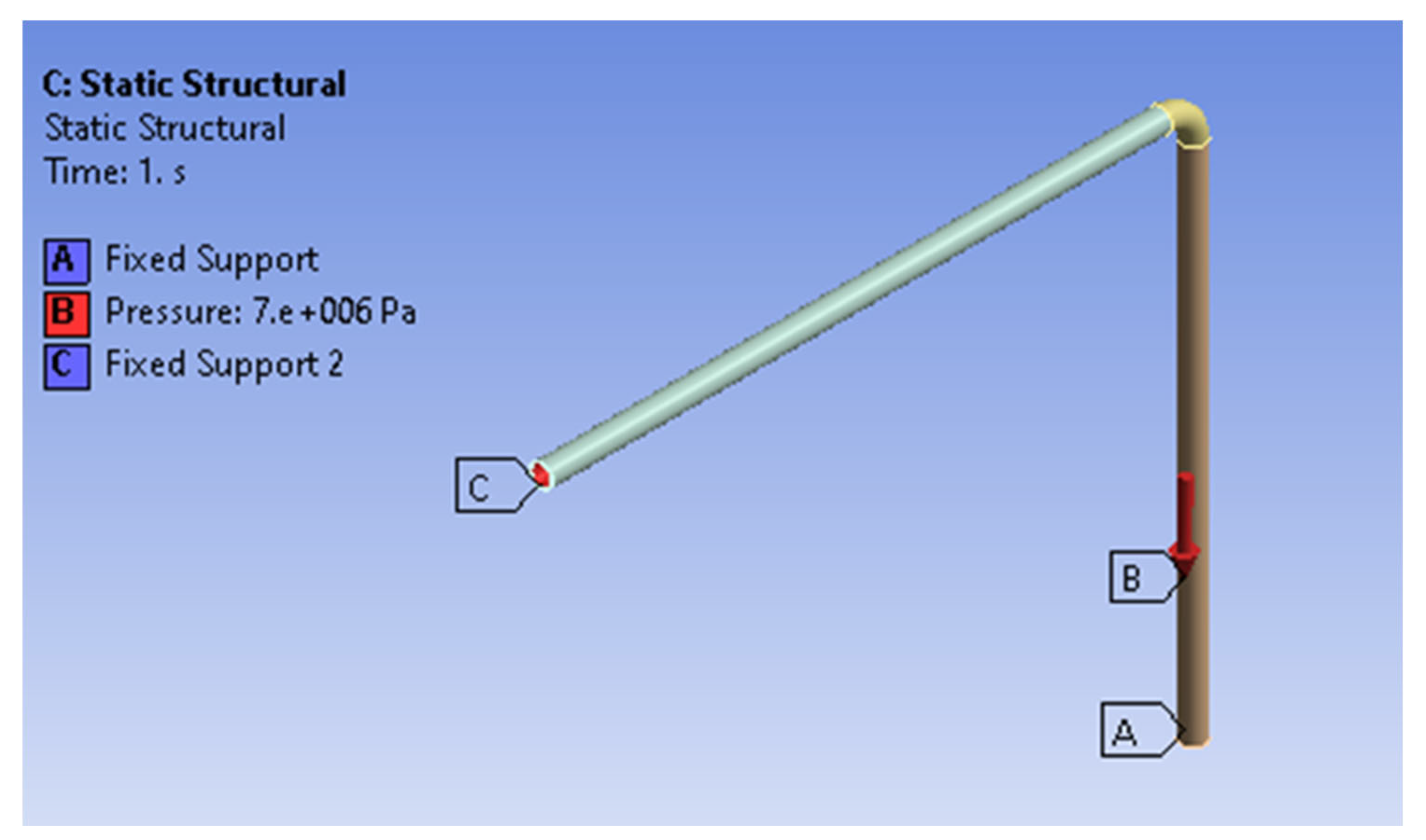
An L-shaped segment consisting of two straight pipe sections joined by a 90° long radius elbow was considered (Figure 1). Its nominal diameter and schedule are 12 inches (304.8 mm) and 80, respectively. The lengths of the pipe legs are 4.5 m for the horizontal section and 4.36 m for the vertical section. The pipe material is SA-106 Gr. C, which is commonly used in the feedwater piping system of the BWR. Its mechanical and physical properties are summarized in Table 1.
Initially, the thermo-mechanical analysis was performed to determine the stress distribution in the pipe model, specifically in the pipe elbow, under the environmental conditions (Section 2.1). Subsequently, an environment-assisted fatigue analysis was performed (Section 2.2). Finally, a fracture analysis was carried out considering a postulated semi-elliptical part-through thickness crack in the internal surface of the pipe elbow (Section 2.3). It was aligned along the axial plane.
A cycle, considered in this evaluation, is between the start-up and shutdown. It takes place when there is a reactor refuelling, an inspection, or an emergency shutdown of the reactor. According to [19], 80 and 120 cycles occur during 40 and 60 years of operation, respectively.
Nuclear regulations aim to address various aspects that impact design and operation. For this reason, they have been followed in the development of the reported work. Specifically, Section 3 [8] of the ASME code establishes the design guidelines for components of nuclear power plants. Section XI [20] of this code establishes the inspection requirements for safety-related components, as well as the guidelines for conducting fracture mechanics evaluations. NUREG/CR-6909 [15] establishes the criteria for determining fatigue life by considering the temperature, strain rate, and dissolved oxygen (DO) level in the water. In addition, the sulphur content in carbon and low-alloy steels is considered. Some of these criteria are based on experimental findings.

2.1. Thermo-Mechanical Analysis

A thermal analysis of the pipe system during the start-up and shutdown transients of a BWR-5 was carried out. They have been taken from reference [5]. Figure 2A shows the temperature and pressure variation in the feedwater during start-up. Figure 2B shows the variation in these parameters during shutdown.
During the start-up transient, a very pronounced temperature drop is observed, in which the feedwater temperature changes from approximately 286 °C to 39 °C in a short period. It takes place 18,000 s after the beginning of the start-up. High thermo-mechanical stresses in both the pipe and the elbow are generated. This occurs every time the reactor is started, which can lead to low-cycle thermal fatigue.
Convective heat transfer was established on the inner surface of the pipe, with a film coefficient of 669 W/m2·°C [21]. In the structural mechanical analysis, the temperature gradients in the pipe thickness were the initial conditions. An internal pressure of 7 MPa (normal operating pressure of the reactor) and fixed supports at the ends of the pipe were also considered. The mechanical analysis yielded the deformation amplitudes for each transient considered.
The thermo-mechanical analysis was performed using the ANSYS® code student version 2025 R1. The mesh has 921,816 elements and 3,905,879 nodes. The average quality of the mesh is 0.91. SOLID87, SOLID90, and SURF152 elements were used for the transient thermal analysis. SOLID186, SOLID187, and SURF154 elements were considered for the structural analysis. The elbow mesh was refined. Stress concentrations occur due to the change in geometry. Its cross-section changes from circular to oval, providing the pipe with flexibility.
A computer with an Intel® Core® 7 processor was used. It has 32 GB of RAM and 2 TB of solid-state storage.

2.2. Environmentally Assisted Fatigue Analysis

Environmentally assisted fatigue (EAF) is a critical degradation mechanism in metallic materials exposed to cyclic loads under aggressive environmental conditions. This phenomenon has become particularly relevant in the nuclear industry, where structural components, such as pipes, elbows, and nozzles, operate in environments characterized by high temperatures, pressure, and the presence of chemically active species, including dissolved oxygen and corrosion products. Unlike conventional fatigue evaluated under laboratory conditions in air, EAF incorporates the synergistic effects of the environment. Under these conditions, the fatigue life of the material is significantly reduced. Several studies have demonstrated that the light water reactor (LWR) environment can significantly accelerate crack initiation and propagation. Therefore, understanding this phenomenon is essential to ensure the structural integrity and long-term safety of components operating in these environments.
A fundamental parameter for quantifying the degree of fatigue life cycle utilization of a component under cyclic loads is the cumulative use fatigue factor (CUF). It can be determined with the Palmgren–Miner equation, shown in Equation (1).
C U F = i = 1 k n i N i
where n i represents the number of cycles at a stress magnitude i, and N i is the number of cycles of fatigue resistance of the material for a stress magnitude i.
Based on the Manson–Coffin–Basquin equation [22], the fatigue life cycles were determined for the strain amplitude with experimental data of carbon steel reported in the NUREG/CR-6909 [15]. Meanwhile, the material life cycles were taken from the fatigue curve in the ASME code [8]. This was done considering the strains in the start-up and shutdown transients. This resulted in Equation (2).
ε a = 0.00053 ( 2 N f ) 0.0048 + 0.1166 ( 2 N f ) 0.36
where ε a is the strain amplitude, which is obtained with the finite element method. The first term on the right-hand side of Equation (2) represents high-cycle fatigue, while the second term is low-cycle fatigue, where N f is the number of fatigue life cycles.
Since the CUF is traditionally based on fatigue curves obtained under laboratory conditions (usually in air or vacuum at room temperature), the degrading effects of the actual operating environment are not considered. Therefore, environmental correction factors must be incorporated to adjust the CUF to more realistic operating conditions, such as those in nuclear reactors, to determine environmentally assisted fatigue. These factors modify the fatigue life cycle of the material by considering variables such as temperature, dissolved oxygen concentration, sulphur content, and strain rate. As a result, the corrected environmental CUF (CUFen) provides a more conservative and accurate estimate of the accumulated damage. It is a key tool in assessing the safety and reliability of components subjected to severe operating conditions.
The environmental correction factors for each transient were calculated using Equation (3) [21].
F e n = e x p ( ( 0.003 0.031 ε ˙ * ) S * T * O * )
where S*, T*, O*, and ε ˙ * are the transformed sulphur content (%/wt), transformed metal temperature (°C), transformed dissolved oxygen (ppm), and transformed strain rate (%/s), respectively.
For the problem at hand, the parameters considered in Equation (3) were: 0.015%/wt, 0.14 ppm, 0.001% s−1, for the sulphur content of the steel, the dissolved oxygen content, and the strain rate of the material, respectively. They were considered in the start-up and shutdown transients. Meanwhile, the temperature was 288 °C and 189 °C for the start-up and shutdown transients, respectively.
The CUF, due to environmental fatigue, can be obtained with Equation (4).
C U F e n = C U F 1 × F e n 1 + C U F 2 × F e n 2 + + C U F n × F e n n
where C U F n and F e n n represent the CUF and the environmental correction factor for the nth transient, respectively.
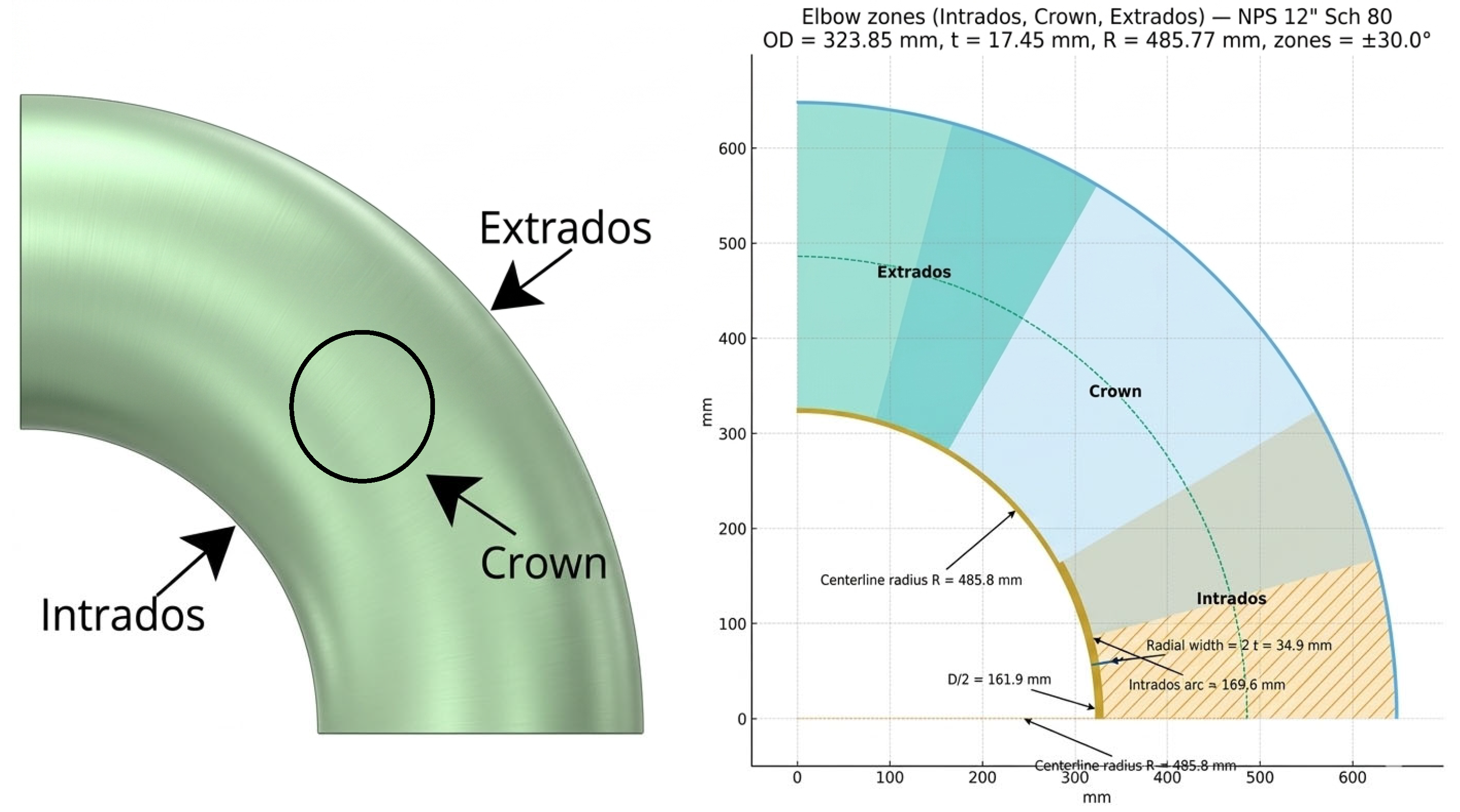
The fatigue analysis was conducted at the intrados, extrados, and crown areas of the pipe elbow (Figure 3).

2.3. Fracture Analysis

As previously mentioned, environmental fatigue takes place in the reactor feedwater piping system. This is particularly pronounced at the system’s elbows. This is mainly due to the transients during reactor start-up and shutdown. Ageing of the pipe material is triggered. Combined with imperfections in the material’s microstructure and the loading conditions, this leads to crack initiation.
An analysis using the failure assessment diagram (FAD) was carried out in accordance with ASME B&PVC, Section XI, Article H-4000 [20]. It is based on two parameters: The first (Kr) is the ratio between the stress intensity factor and the fracture toughness of the material. The other parameter (Sr) is the ratio between the applied stress and the reference stress, which is usually the material’s creep resistance. Equation (5), which is considered in code R6 [23], has been plotted in the diagrams. It is represented by the red curve.
K r = ( 1 0.14 S r 2 ) [ 0.3 + 0.7 e x p ( 0.65 S r 6 ) ]
This curve divides the graph into two zones. The lower zone is the safe zone. Conversely, the upper zone is where failure occurs.
Three modes of failure can be identified in the safe zone. A brittle fracture takes place when the following relationship is satisfied. The brittle failure zone in the FAD is limited by the vertical axis, the failure curve, and the straight magenta line.
K r S r > 1.8
An elastic–plastic failure takes place when the following relation is satisfied. Its domain in the FAD is limited by the failure curve and the magenta and blue straight lines.
0.2 < K r S r 1.8
The plastic collapse occurs when the following relationship is satisfied. The region of the FAD, in which this sort of failure takes place, is bounded by the failure curve, the horizontal axis, and the blue straight line.
K r S r 0.2   P l a s t i c   c o l l a p s e
For axial cracks in a pipe under internal pressure, the limit load cut-off for Sr is the vertical dashed green line. It is given by
S r c u t o f f = P l P o
P l is the internal pressure at the collapse limit load for an axial failure, and P o is the reference limit load pressure. Additional details can be found in ASME B&PVC, Section XI, Article H-4000 [20].
Regarding the cases of interest, a semi-elliptical part-through thickness crack was postulated on the inner surface of the crown of the elbow. Its thickness is 17.48 mm. The crack was oriented along the axial plane in accordance with the NUREG/CR-6765 [24]. It establishes guidelines for the evaluation of a cracked pipe. An initial depth of 3 mm was considered, as this size is the minimum detectable, according to the literature.
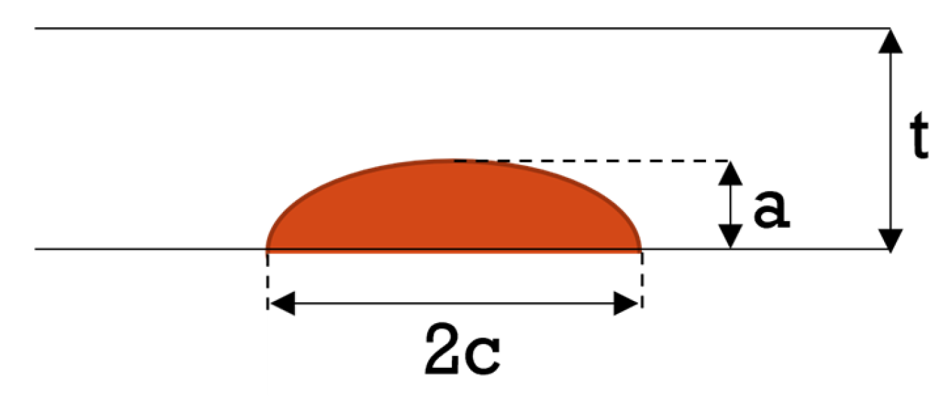
These analyses are intended to evaluate the crack propagation and whether it will grow in a stable or unstable manner. Figure 4 shows a representation of the crack geometry. The crack depth, the crack length, and pipe thickness are a, 2c, and t, respectively.
Table 2 shows the parameters considered for four analyzed cases of the postulated crack. The internal pressure was kept constant at 7 MPa for the first three cases. In the fourth case, evaluations were performed for pressures of 7 MPa, 10 MPa, and 15 MPa.
In the first case, the a/c ratio has been kept constant (0.5), while in the second case, the depth is constant (3 mm). In the third case, the half-length c (96 mm) remains constant in the evaluations. In the fourth case, the sensitivity of the assessment is evaluated. Combinations of the geometric parameters of the cracked elbow subjected to various pressures were assessed. More details of case 4 are given in the results Section 3.

3. Results

3.1. Thermo-Mechanical Analysis

Based on the transient thermal analysis of the 90° long radius elbow, the temperature gradient across its thickness was determined. Convective heat transfer was considered with a film coefficient of 669 W/m2·°C. The water temperature was 38 °C. The initial pipe temperatures for start-up and shutdown transients were 286 °C and 189 °C, respectively.
Figure 5A,B shows the temperature field of the internal surface and the thickness along an axial plane of the elbow. The first case corresponds to 18,000 s after the start-up transient begins. This is the point at which the temperature reaches its maximum (Figure 2A). The last case illustrates the temperature field 7200 s after the shutdown transient begins (Figure 2B).
As expected, the inner surface tends to cool more quickly because it is in direct contact with the water.
The temperature gradients obtained in the transient thermal analysis are the initial conditions in the structural analysis. The internal pressure in the pipe was taken as a uniform pressure of 7 MPa. Both ends of the pipe were considered fixed (Figure 1), which is the most critical case.
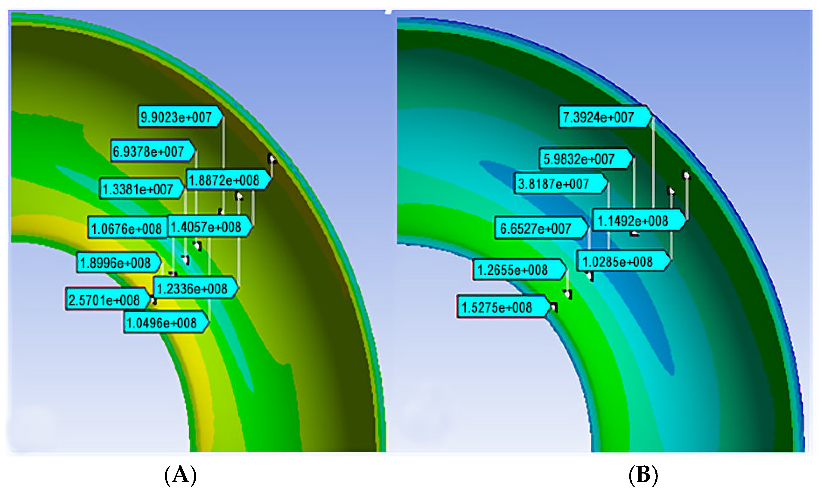
Due to the intensification of stresses and the oval geometry of the cross-section of the elbow, stress concentrations are developed. The stress analysis focused on this area. Figure 6 shows the stress distribution on the inner surface of the elbow for the start-up (A) and stop (B) transients. The figure shows some labels of the stress value in the middle of the inner surface of the elbow. As can be seen, the stresses are greater in the intrados area.

3.2. Environmentally Assisted Fatigue Analysis

For the fatigue analysis, the three areas of the elbow (intrados, crown, and extrados, as shown in Figure 3) were evaluated. In each case, one point on the inner surface was considered. The fatigue cycles considered are the reactor start-up and shutdown transients. Table 3 summarizes the results of the fatigue life cycles for A106 Gr. C steel for the three areas of the elbow on the inner surface of the elbow. Equation (3) was solved with Matlab® code version R25a. The strains determined by ANSYS® were considered.
About the CUF, Table 4 summarizes the results for 40 and 60 years of operation. This parameter is dimensionless and much less than one. Therefore, it is considered safe. Failure occurs when this value exceeds one.
Table 5 shows the results obtained for the CUF considering the environmental conditions in the reactor for start-up and shutdown transients over 40 and 60 years of operation. They are lower than one. Therefore, it is considered safe.
Based on the information reported in the previous tables, the area of the elbow most susceptible to fatigue is the intrados on the inner surface.

3.3. Fracture Analysis

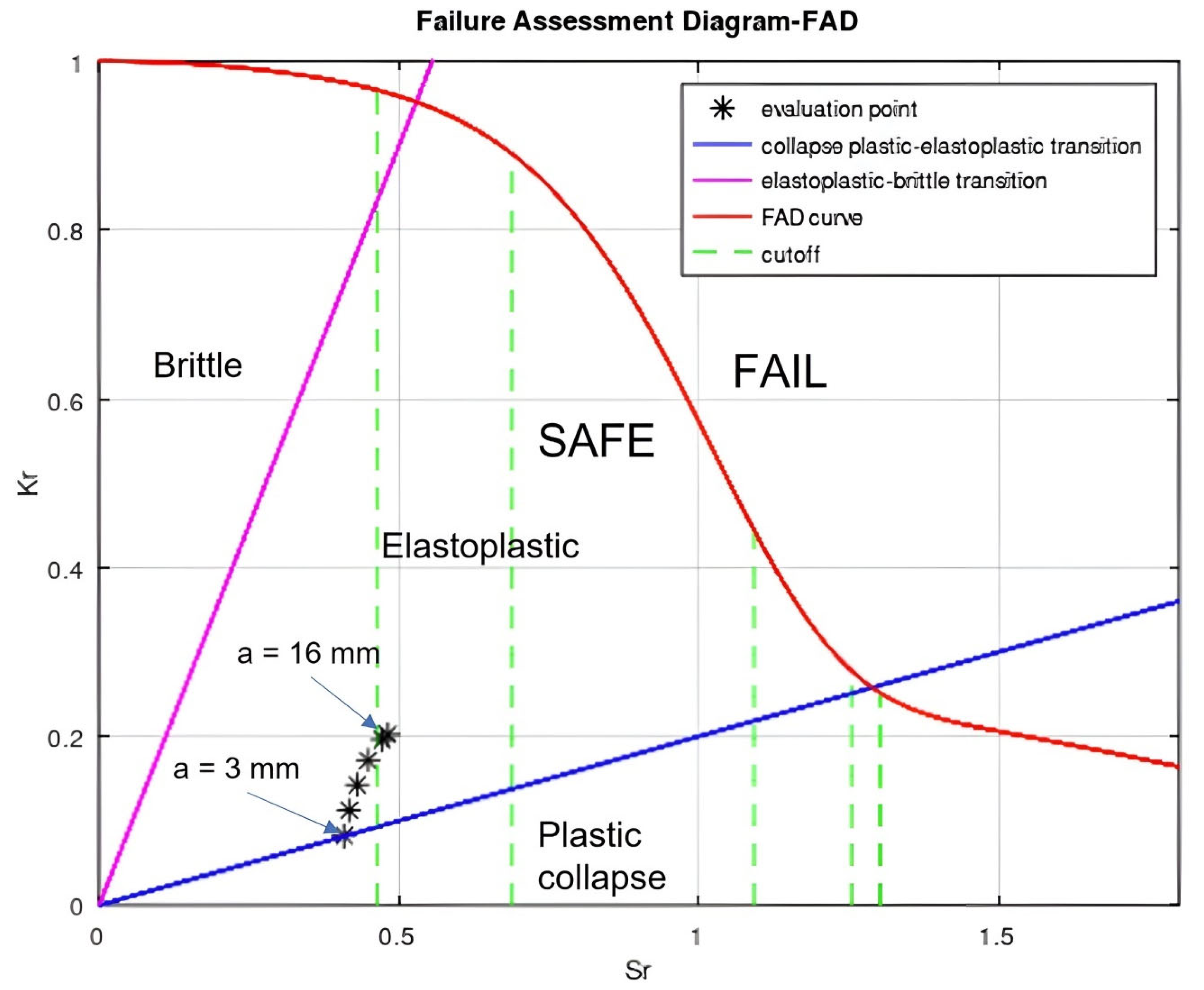
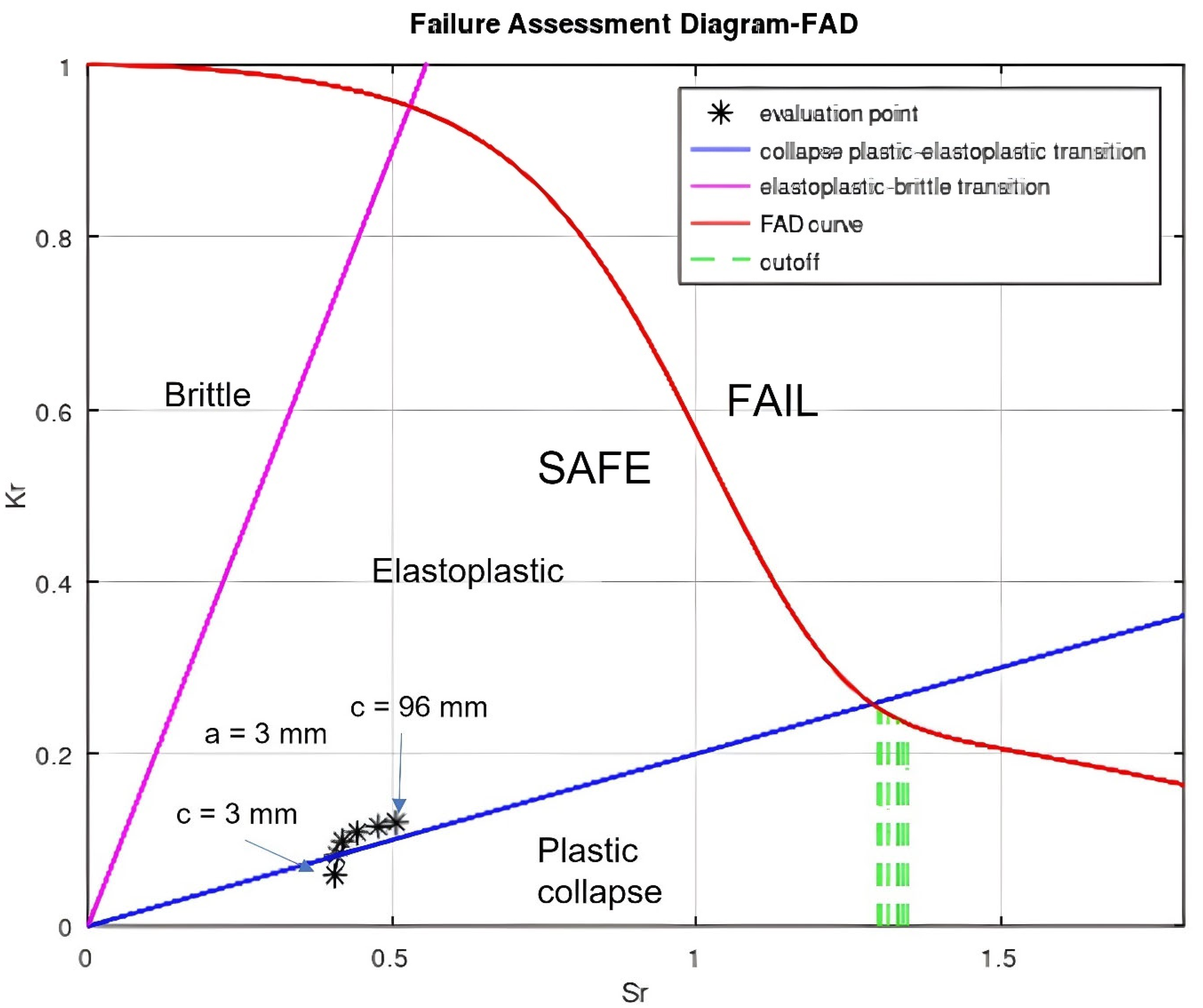
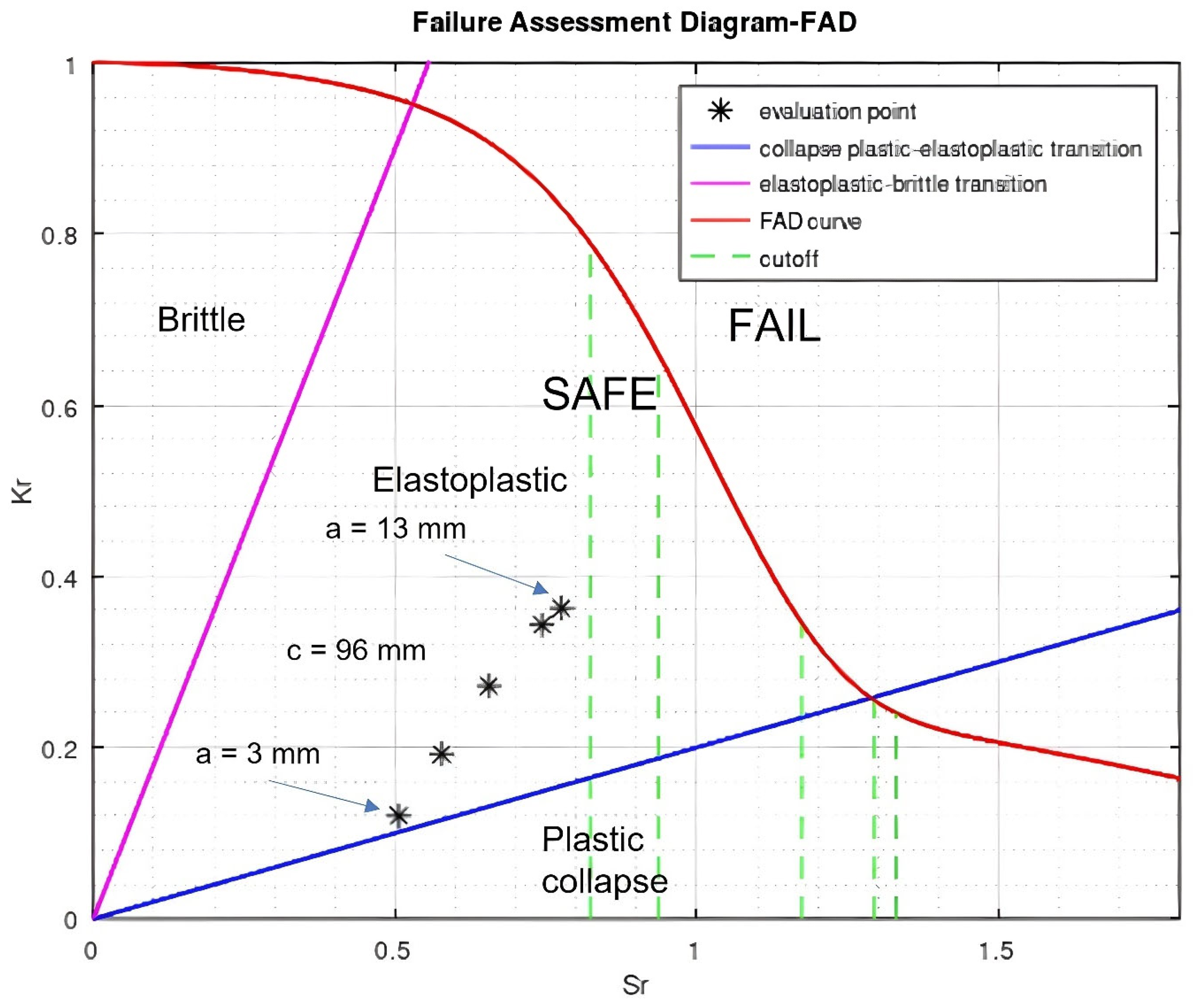
Figure 7, Figure 8, Figure 9 and Figure 10 show the results of the analysis with the FAD for the cases summarized in Table 2. As this is an axial crack, the ASME code recommends considering the cutoff. It would be the condition in which local inelasticity can be developed. This situation is represented by the vertical green lines.
Case 1.
The minimum crack depth of 3 mm is detectable [20,24]. For this reason, the propagation of the postulated crack was analyzed over a depth range of 3–16 mm. The a/c ratio was kept constant (0.5). Six evaluations were performed when the elbow was loaded with an internal pressure of 7 MPa.
The results in Figure 7 show that the material changes from plastic collapse to elastoplastic, as the depth of the crack increases. All assessment points are in the safe zone. However, the points representing a crack depth of 15 mm and 16 mm are located close to the vertical dotted line. It is the cutoff. According to ASME Code Section XI, Appendix H, it indicates that the FAD is not applicable. Furthermore, the maximum tolerable depth is 75% of the elbow thickness. In this case, it is 13 mm. Both cases mentioned above are greater than this depth.
Case 2.
Figure 8 shows the results when the crack depth is kept constant at 3 mm, and its length (2c) is varied from 6 mm to 192 mm. The evaluation points are located near the transition zone between plastic collapse and elastoplastic behaviour. As can be seen in Figure 8, varying the crack length while keeping the depth constant does not have much influence. However, if failure occurs in the material, it would probably be due to plastic collapse.
Case 3.
Figure 9 shows the behaviour of the crack when its depth varies from 3 mm to 13 mm, and the length (2c) remains at a constant value of 192 mm. All evaluation points fall within the elastoplastic zone. The depth of the crack has a significant influence on the stress intensity factor ratio, as well as on the stress ratio. Also, the evaluation point for the crack depth of 13 mm is very close to the cutoff, indicating high local plastic deformation.
Case 4.
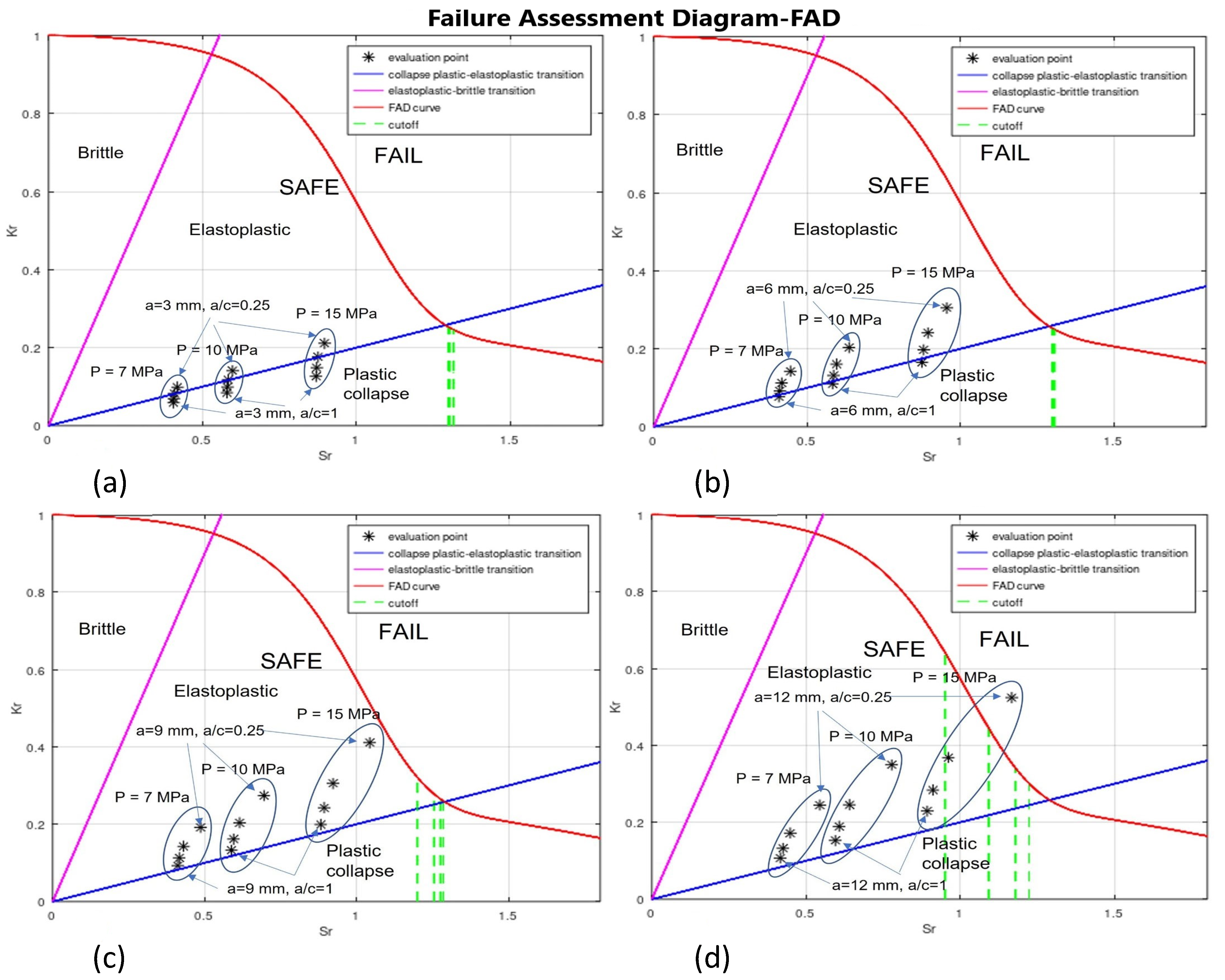
In this case, four sets of analyses were performed. They are summarized in Table 6. The objective is to evaluate the effect of crack depth on the structural integrity of an elbow. Three load cases were considered (7 MPa, 10 MPa, and 15 MPa).
In set A, the crack depth was 3 mm, and the a/t ratio remained constant (0.17). Four half-crack lengths were considered. A similar situation was considered in the sets B, C, and D. The crack depth was 6 mm, 9 mm, and 12 mm, and the a/t was 0.34, 0.51, and 0.69, respectively. It has been summarized in Table 6.
The behaviour is predominantly plastic in Figure 10a. The increase in pressure produces a slight increase in Sr and Kr, without structural risk. In Figure 10b, the evaluation is in the safe zone of the elastoplastic area. The component remains safe, but with greater plastic deformation and a lower safety margin as the pressure increases. In Figure 10c, the points at a pressure of 15 MPa are significantly closer to the border of the safe zone. The pressure increase is relevant. Deeper cracks have a greater risk than the superficial ones. In Figure 10d, the points of highest pressure practically reach or exceed the safety limit, indicating that under these conditions, the component would be at risk of structural failure. For large cracks and high pressures, the component loses its structural integrity.

4. Discussion

The results show the critical influence of environmental factors on the fatigue behaviour of pipe elbows under boiling water reactor (BWR) conditions. Specifically, it was found that the inner surface of the elbow intrados is the area most susceptible to environment-assisted fatigue (EAF), which is consistent with previous observations on stress intensification due to geometric transitions in pipe elbows [6].
A significant reduction in fatigue life was observed when environmental correction factors (Fen) were applied in locations exposed to high thermal gradients and cyclic loads. This is consistent with the findings of Chopra et al. [15], who demonstrated that the fatigue life of low-alloy steels in light water reactor (LWR) environments can be reduced by up to a factor of 50 compared to atmospheric environments. The empirical formulations of Fen used in this work were derived from the methodology proposed by Stevens [21] and Chopra and Shack [14], and their integration into the fatigue analysis provides a more realistic assessment of the durability of components under actual service conditions.
In addition, the influence of strain rate and metal temperature, two key variables in the equation for determining Fen, was evident in the results. The BWR start-up transient, characterized by a strong thermal shock at approximately 18,000 s, resulted in higher deformation amplitudes and, therefore, lower fatigue life predictions, especially on the inner surface of the elbow intrados. These results support the experimental observations of Higuchi and Iida [16], who highlighted that low strain rates and high temperatures (typically >250 °C) significantly increase susceptibility to EAF due to increased oxidation and hydrogen absorption kinetics.
The FADs developed in this work confirm that crack depth (a) is the main parameter influencing the transition between ductile and elastoplastic failure regimes. As crack depth increases, the behaviour of the system shifts toward the elastoplastic domain, indicating a reduced margin for defect tolerance under internal pressure conditions.
From a methodological perspective, the finite element approach employed, which uses thermo-mechanical coupling, demonstrates strong alignment with ASME B&PVC Section III and XI standards [8,20]. The combination of fatigue damage estimation using the Palmgren–Miner rule and crack growth analysis using Paris’s law provides a solid framework for assessing structural integrity during long-term operation, as also supported by NUREG/CR-6909 [15] and EPRI guidelines.
However, it should be noted that the cumulative usage factors (CUF and CUFen) obtained remain well below the design threshold of 1.0, even after considering 60 years of operation. This suggests a level of conservatism in the design methodologies, as also discussed in references [9,10], where alternative fatigue curves and environmental correction proposals are suggested to optimize design margins without compromising safety.
On the other hand, the ASME code for boilers and pressure vessels details the procedure for performing fatigue and fracture analyses of materials. However, the results obtained with this methodology are, in most cases, conservative for small defects. This is because pipe deformations, defective welds, corrosion, and additional bending stresses in the ordinary, extraordinary, and emergency operations that occur during the service life of a piping system are not considered [25].
Although hydrogen-induced degradation mechanisms were not explicitly modelled in this work, recent advances suggest that hydrogen absorption in regions under stress, especially under low-cycle fatigue, can further accelerate crack initiation and propagation [26]. The work of Fernández-Sousa et al. [27] and Golahmar et al. [28] demonstrates that hydrogen-enhanced localized plasticity (HELP) and debonding mechanisms can be incorporated into fatigue crack growth models to improve the accuracy of predictions.
On the other hand, in addition to the environmental and corrosive conditions of the fluid transported, the operating time of the pipe system must be considered. It is important to determine how the base material’s microstructure is affected by prolonged exposure to the corrosive environment and the operating conditions of the pipeline. As an example, the case study by Vira et al. [29] can be mentioned. They studied the degradation of the base material of a steel pipeline that transported gas for 31 years and analyzed the impact on the fatigue crack growth rate.
It would also be advisable to consider that the reactor feedwater piping is exposed to long-term operations, which, due to both internal and external environmental conditions, have a degrading effect on the steel’s microstructure. However, conducting experimental tests at the reactor site is extremely complex due to the radioactive environment and very strict safety regulations. Nevertheless, environmental penalty factors are an option accepted by the scientific community dedicated to these issues.
Finally, future research should explore the incorporation of advanced material degradation models, particularly those involving hydrogen diffusion and trap-based kinetics, as well as dissimilar metal weld (DMW) analysis. The development of multiscale models that combine thermo-mechanical loading with microstructural evolution would significantly improve the predictive capability of current methodologies. In addition, calibrating FEM-based methods using plant-specific operating transients, as suggested by EPRI, could reduce unnecessary conservatism and improve maintenance planning.

5. Conclusions

Nuclear power plants are expected to operate for many years. During their service life, they are exposed to ordinary, extraordinary, and emergency load conditions. These can generate elastoplastic conditions in the materials of the nuclear reactors and their components, which are exacerbated by the stress contraction due to the geometry of the elbows. Furthermore, contact of the internal walls with water generates environmentally assisted fatigue (EAF) due to corrosion. The latter is a complex process. However, penalty factors simplify the analysis. These have been accepted in the nuclear sector. All these factors allow for an evaluation of the components associated with the reactor cooling system.
Some research, such as that discussed in this paper, has been carried out on the degradation of the material in carbon steel pipe elbows, caused by the corrosive environment of the transported fluid and the loading conditions.
Roos et al. [30] analyzed two circumferential cracks, one postulated in the crown and the other in the extrados of the elbow. The feedwater conditions of a pressurized water reactor (PWR) were taken into account. The postulated crack in the crown was axial, and the one in the extrados was circumferential.
Similarly, Kussmaul et al. [31] evaluated the causes of a circumferential crack detected in the main feedwater pipe of a boiling water reactor (BWR). Cracks in two elbows of the reactor’s water purification system piping were also analyzed due to the presence of a longitudinal crack.
Kamaya [32] evaluated the damage caused by local fluctuations in fluid temperature at the elbow of a branch of the reactor’s main feedwater pipe. It was analyzed numerically and experimentally to calculate the thermal stress and its fluctuation. Although these studies analyze fractures at elbows in nuclear reactor feedwater pipes, they use different methodologies than those described here. They do not consider the use of environmental penalty factors.
In this work, the environmentally assisted fatigue (EAF) behaviour and fracture assessment of a 90° long elbow were analyzed, considering the actual operating conditions in the feedwater pipe of a BWR. Based on the reactor start-up and shutdown transients, a thermo-mechanical analysis was performed to determine the stress field in the elbow, as these elements are the most vulnerable due to stress intensification and, considering the transients, are prone to fatigue damage. Hernández-Gómez et al. [33] determined numerically that damage is increased as the temperature of the injected water is reduced.
The results indicated that the area most vulnerable to fatigue damage is located on the inner surface of the elbow, due to the intensification of stresses caused by the curved geometry. Significant reductions in fatigue life were observed when environmental correction factors (CUFen) were incorporated, particularly in the presence of high temperatures, low deformation rates, and dissolved oxygen, parameters consistent with reactor operation.
Furthermore, failure assessment diagrams (FADs) revealed that crack depth is the most influential parameter in the change in failure regime, indicating a clear transition to elastoplastic behaviour as the crack grows. The application of Paris’s law and the probabilistic approach under ASME XI code allowed for an accurate evaluation of the postulated surface crack growth on the inner surface of the elbow crown.
Despite the severe conditions considered, the CUF and CUFen values remained below the design threshold, suggesting adequate structural safety margins for the component evaluated. These results allow for the establishment of a robust methodology for evaluating the structural integrity of components in nuclear plants, considering both environmental conditions and actual thermal transients during operation.

Author Contributions

Conceptualization, L.R.-C., L.H.H.-G., and R.G.-I.; methodology, L.R.-C., L.H.H.-G., F.G.-M. and R.G.-I.; software, L.R.-C., M.A.G.-E., and A.V.G.; validation, L.R.-C., L.H.H.-G., and R.G.-I.; formal analysis, L.R.-C., L.H.H.-G., and R.G.-I.; investigation, L.R.-C. and A.A.-M.; resources, L.R.-C. and A.A.-M.; data curation, A.A.-M.; writing—original draft preparation, L.R.-C. and L.H.H.-G.; writing—review and editing, L.R.-C., L.H.H.-G.; supervision, L.H.H.-G. and R.G.-I.; project administration, L.H.H.-G., A.A.-M.; funding acquisition, L.H.H.-G. All authors have read and agreed to the published version of the manuscript.

Funding

This research was supported by the grant 211704 of CONAHCYT.

Institutional Review Board Statement

Not applicable.

Informed Consent Statement

Not applicable.

Data Availability Statement

The data used to support the findings of this study are available from the corresponding authors upon request.

Acknowledgments

The authors acknowledge the grant 211704 of the Consejo Nacional de Humanidades Ciencia y Tecnología (CONAHCYT of México) that supported this research. All the authors recognize Pablo Ruiz Lopez’s contribution to this research.

Conflicts of Interest

The authors declare no conflicts of interest.

Abbreviations

The following abbreviations are used in this manuscript:
ASMEAmerican Society of Mechanical Engineers
B&PVCBoiler and Pressure Vessel Code
BWRBoiling Water Reactor
CUFCumulative Usage Factor
CUFenCumulative Usage Factor—Environmental
DMWDissimilar Metal Welds
EAFEnvironmentally Assisted Fatigue
FADFailure Assessment Diagram
HELPHydrogen Enhanced Localized Plasticity
LWRLight Water Reactor
NUREGNuclear Regulatory Commission Report

References

  1. Arora, P.; Singh, P.K.; Bhasin, V.; Vaze, K.K.; Pukazhendhi, D.M.; Gandhi, P.; Raghava, G. Fatigue Crack Growth Behavior in Pipes and Elbows of Carbon Steel and Stainless Steel Materials. Procedia Eng. 2013, 55, 703–709. [Google Scholar] [CrossRef] [Scilit]
  2. Schuler, X.; Herter, K.H. Thermal Fatigue Due to Stratification and Thermal Shock Loading of Piping. In Proceedings of the 30. MPA-Seminar in Verbindung Mit Dem 9. Deutsch-Japanischen Seminar, Stuttgart, Germany, 6–7 October 2004. [Google Scholar]
  3. Paffumi, E.; Nilsson, K.; Taylor, N.G. Simulation of Thermal Fatigue Damage in a 316L Model Pipe Component Japan Society of Mechanical Engineers. Int. J. Press. Vessel. Pip. 2008, 85, 798–813. [Google Scholar] [CrossRef] [Scilit]
  4. Nilsson, K.; Dolci, F.; Seldis, T.; Ripplinger, S.; Grah, A.; Simonovski, I. Assessment of Thermal Fatigue Life for 316L and P91 Pipe Components at Elevated Temperatures. Eng. Fract. Mech. 2016, 168, 73–91. [Google Scholar] [CrossRef] [Scilit]
  5. Evon, K.; Gilman, T.; Walter, M. Fatigue Monitoring of BWR Feedwater Nozzles. In ASME 2013 Pressure Vessels and Piping Conference; ASME: New York, NY, USA, 2013; p. V01AT01A038. [Google Scholar]
  6. Harun, M.F.; Mohammad, R.; Kotousov, A. Low Cycle Fatigue Behavior of Elbows with Local Wall Thinning. Metals 2020, 10, 260. [Google Scholar] [CrossRef] [Scilit]
  7. Simonen, F.A.; Khaleel, M.A.; Phan, H.K.; Harris, D.O.; Dedhia, D.D.; Kalinousky, D.N.; Shaukat, S.K. Evaluation of Environmental Effects on Fatigue Life of Piping. Nucl. Eng. Des. 2001, 208, 143–165. [Google Scholar] [CrossRef] [Scilit]
  8. ASME International. ASME Boiler and Pressure Vessel Code Section III, Division 1—Appendices Rules for Construction of Nuclear Facility Components, 2010th ed.; ASME International: New York, NY, USA, 2010. [Google Scholar]
  9. Donnell, W.J.O.; Donnell, W.J.O.; Donnell, T.P.O. Proposed New Fatigue Design Curves for Austenitic Stainless. In ASME Pressure Vessels and Piping Division Conference; ASME: Denver, CO, USA, 2005; pp. 109–132. [Google Scholar]
  10. O’Donnell, W.J.; O’Donnell, T.P. Proposed New Fatigue Design Curves for Carbon and Low-Alloy Steels in High Temperature Water. J. Press. Vessel Technol. Trans. ASME 2009, 131, 024003. [Google Scholar] [CrossRef] [Scilit]
  11. Chopra, O.K. Development of Fatigue Design Curve for Austenitic Stainless Steels in LWR Environments: A Review. In ASME Pressure Vessels and Piping Conference; ASME Press: Vancouver, BC, Canada, 2002; pp. 119–132. [Google Scholar]
  12. Chopra, O.K.; Michaud, W.F.; Shack, W.J. Fatigue of Carbon and Low-Alloy Steels in LWR Environments. In Proceedings of the 21st Water Reactor Safety Information Meeting; U.S. Nuclear Regulatory Commision: Bethesda, MD, USA, 1993. [Google Scholar]
  13. Chopra, O.K.; Shack, W.J. Overview of Fatigue Crack Initiation in Carbon and Low-Alloy Steels in Light Water Reactor Environments. J. Press. Vessel Technol. Trans. ASME 1999, 121, 49–60. [Google Scholar] [CrossRef] [Scilit]
  14. Chopra, O.K.; Shack, W.J. Methods for Incorporating the Effects of LWR Coolant Environments in Pressure Vessel and Piping Fatigue Evaluations. In Proceedings of the Second International Conference on Fatigue of Reactor Components, Snowbird, UT, USA, 29–31 July 2002; pp. 674–691. [Google Scholar]
  15. Chopra, O.K.; Stevens, G.L. Effect of LWR Water Environments on the Fatigue Life of Reactor Materials, NUREG/CR-6909, Rev.1; Final Report; U.S. Nuclear Regulatory Commission: Washington, DC, USA, 2018.
  16. Higuchi, M.; Iida, K. Fatigue Strength Correction Factors for Carbon and Low-Alloy Steels in Oxygen-Containing High-Temperature Water. Nucl. Eng. Des. 1991, 129, 293–306. [Google Scholar] [CrossRef] [Scilit]
  17. Higuchi, M. Revised Proposal of Fatigue Life Correction Factor Fen for Carbon and Low Alloy Steels in LWR Water Environments. J. Press. Vessel Technol. Trans. ASME 2004, 126, 438–444. [Google Scholar] [CrossRef] [Scilit]
  18. Sakaguchi, K.; Suzuki, S.; Kanasaki, H.; Nomura, Y.; Tsutsumi, K.; Higuchi, M. Effect of Factors on Fatigue Life in PWR Water Environment. In ASME Pressure Vessels and Piping Division Conference; ASME: Vancouver, BC, Canada, 2006; pp. 103–111. [Google Scholar]
  19. Evon, K.; Gilman, T.; Walter, M. Fatigue Life of BWR Feedwater Nozzles Considering Actual Plant Transients. In Pressure Vessels and Piping Conference; ASME: Vancouver, BC, Canada, 2014; p. V003T03A066. [Google Scholar]
  20. Boiler and Pressure Vessel Committee on Nuclear Inservice Inspection. Section XI Rules for Inservice Inspection of Nuclear Power Plant Components; ASME: New York, NY, USA, 2010. [Google Scholar]
  21. Stevens, G.L. Environmentally Assisted Fatigue Screening Methods (Revision 1); EPRI: Palo Alto, CA, USA, 2020. [Google Scholar]
  22. Campbell, F.C. Fatigue and Fracture-Understanding the Basics; Campbell, F.C., Ed.; ASM International: New York, NY, USA, 2012; ISBN 9781615039760. [Google Scholar]
  23. Milne, I.; Ainsworth, R.A.; Dowling, A.R.; Stewart, A.T. Assessment of the Integrity of Structures Containing Defects. Int. J. Press. Vessel. Pip. 1988, 32, 3–104. [Google Scholar] [CrossRef] [Scilit]
  24. Scott, P.; Olson, R.J.; Wilkowski, G.M. NUREG/CR-6765 Development of Technical Basis for Leak-Before-Break Evaluation Procedures; Division of Engineering Technology, Office of Nuclear Regulatory Research, US Nuclear Regulatory Commission: Washington, DC, USA, 2002. [Google Scholar]
  25. Chmelko, V.; Garan, M.; Berta, I. Calculation of burst pressure of pipeline with local defect. Procedia Struct. Integr. 2020, 26, 417–421. [Google Scholar] [CrossRef] [Scilit]
  26. González-Velázquez, J.L. A Practical Approach to Fracture Mechanics; Elsevier: Cambridge, MA, USA, 2021; ISBN 9780128230206. [Google Scholar]
  27. Fernández-Sousa, R.; Betegón, C.; Martínez-Pañeda, E. Cohesive Zone Modelling of Hydrogen Assisted Fatigue Crack Growth: The Role of Trapping. Int. J. Fatigue 2022, 162, 106935. [Google Scholar] [CrossRef] [Scilit]
  28. Golahmar, A.; Kristensen, P.K.; Niordson, C.F.; Martínez-Pañeda, E. A Phase Field Model for Hydrogen-Assisted Fatigue. Int. J. Fatigue 2022, 154, 106521. [Google Scholar] [CrossRef] [Scilit]
  29. Vira, V.; Krechkovska, H.; Kulyk, V.; Duriagina, Z.; Student, O. Peculiarities of Fatigue Crack Growth in Steel 17H1S after Long-Term Operations on a Gas Pipeline. Materials 2023, 16, 2964. [Google Scholar] [CrossRef] [Scilit] [PubMed]
  30. Roos, E.; Herter, K.H.; Schuler, X.; Chattopadhyay, J.; Kushwaha, H.S. Integrity Assessment for Safety-Related Nuclear Piping. Int. J. Press. Vessel. Pip. 2014, 123, 46–59. [Google Scholar] [CrossRef] [Scilit]
  31. Kussmaul, K.; Blind, D.; Jansky, J. Cracking in Feedwater Pipework of Light Water Reactors: Causes and Remedies. Int. J. Press. Vessel. Pip. 1984, 17, 83–104. [Google Scholar] [CrossRef] [Scilit]
  32. Kamaya, M. Assessment of Thermal Fatigue Damage Caused by Local Fluid Temperature Fluctuation (Part I: Characteristics of Constraint and Stress Caused by Thermal Striation and Stratification). Nucl. Eng. Des. 2014, 268, 121–138. [Google Scholar] [CrossRef] [Scilit]
  33. Hernández-Gómez, L.H.; Pérez-Escobar, B.L.; Beltrán-Fernández, J.A.; Flores-Campos, J.A.; Pérez-Montejo, S.; Jiménez-Santiago, K.I.; Ruiz-López, P.; Urriolagoitia-Calderón, G.M. Thermal Fatigue Analysis in a High Pressure Cooling System (HPCS) Nozzle of a Boling Water Reactor. Defect Diffus. Forum 2017, 370, 162–170. [Google Scholar] [CrossRef] [Scilit]
Figure 1. Pipe system (12 inches (304.8 mm) nominal diameter) analyzed. The end C is joined to the feedwater nozzle, both ends are fixed, and the internal pressure is 7 × 10⁶ Pa.
Applsci 16 02782 g001
Figure 2. Thermal and pressure transients in a BWR-5. (A) Start-up. (B) Shutdown.
Applsci 16 02782 g002
Figure 3. The intrados, extrados, and crown zones of a 12-inch (304.8 mm) nominal diameter, schedule 80, 90° long radius elbow, and its dimensions.
Applsci 16 02782 g003
Figure 4. Geometry of a part-through thickness elliptical crack in the axial direction.
Applsci 16 02782 g004
Figure 5. Temperature field [°C] (A) at 18,000 s after the start-up transient initiation, (B) at 7200 s after the shutdown initiation.
Applsci 16 02782 g005
Figure 6. Stress field [Pa] on the internal surface of the elbow. (A) Start-up (B) shutdown.
Applsci 16 02782 g006
Figure 7. Failure assessment diagram when the range of the crack length is between 12 mm and 64 mm and the depth-to-half-length ratio of the crack (a/c) is 0.5. The internal pressure is 7 MPa.
Applsci 16 02782 g007
Figure 8. Failure assessment diagram when the crack depth is 3 mm, and its length (2c) varies between 6 mm and 192 mm. The internal pressure is 7 MPa.
Applsci 16 02782 g008
Figure 9. Failure assessment diagram when the crack depth varies in the range between 3 mm and 13 mm. Its length (2c) is 192 mm. The internal pressure is 7 MPa.
Applsci 16 02782 g009
Figure 10. Failure assessment diagram for a/c ratio in the range between 1 and 0.25. The internal pressure is 7 × 10⁶ Pa, 10 × 106 Pa, and 15 × 106 Pa, for crack depths of: (a) 3 mm; (b) 6 mm; (c) 9 mm; (d) 12 mm.
Applsci 16 02782 g010
Table 1. Physical properties of A106 Gr. C steel.
PropertyTensile Strength (MPa)Yield Strength (MPa)Young’s Modulus (GPa)Poisson’s RatioFracture Toughness (MPa-m1/2)Density (kg/m3)
Mechanical4832371880.31587750
PropertyThermal Expansion Coefficient (mm/mm°C)Thermal Conductivity Coefficient (W/m°C)Thermal Diffusivity Coefficient (m2/s)Specific Heat (J/kg°C)
Thermal12.753.613.4516.13
Table 2. Analyzed cases.
ParameterCase 1Case 2
Crack depth a (mm)3691215163
Crack half-length c (mm)612182430323612244896
a/c   ratio0.510.50.250.1250.06250.3125
a/t   ratio0.170.340.510.690.860.920.17
Internal pressure (MPa)77
Case 3Case 4
Crack depth a (mm)36912133, 6, 9 and 12
Crack half-length c (mm)963, 4, 6, 8, 9, 12, 16, 18, 24, 36 and 48
a/c   ratio0.031250.06250.093750.1250.13541, 0.75, 0.5 and 0.25
a/t   ratio0.170.340.510.690.740.17, 0.34, 0.51 and 0.69
Internal pressure (MPa)77, 10 and 15
Table 3. Fatigue life cycles for A106 Gr. C steel, considering the BWR start-up and shutdown transients.
ZoneStart-upShutdown
Internal Surface
(Number of Cycles)
Internal Surface
(Number of Cycles)
Intrados8.07 × 1051.72 × 107
Extrados4.10 × 1061.14 × 109
Crown3.98 × 1010infinite
Table 4. Cumulative fatigue factor for A106 Gr. C steel for start-up and shutdown transients, considering 40 and 60 years of operation.
Zone40 Years60 Years
Internal SurfaceInternal Surface
Intrados1.04 × 10−41.56 × 10⁻⁴
Extrados1.82 × 10−52.73 × 10⁻⁵
Crown2.01 × 10−93.02 × 10⁻⁹
Table 5. Cumulative environmental fatigue factor for A106 Gr. C steel for start-up and shutdown transients, considering 40 and 60 years of reactor operation.
Zone40 Years60 Years
Internal SurfaceInternal Surface
Intrados1.32 × 10−31.98 × 10⁻³
Extrados2.38 × 10−43.57 × 10⁻⁴
Crown2.64 × 10−83.96 × 10⁻⁸
Table 6. Parameters considered in the evaluation of case 4.
ParameterABCD
Crack depth a (mm)369 12
Crack half-length c (mm)3 4612681224912183612162448
a/c   ratio10.750.50.2510.750.50.2510.750.50.2510.750.50.25
a/t   ratio0.170.340.510.69
Internal pressure (MPa)71015710157101571015
Disclaimer/Publisher’s Note: The statements, opinions and data contained in all publications are solely those of the individual author(s) and contributor(s) and not of MDPI and/or the editor(s). MDPI and/or the editor(s) disclaim responsibility for any injury to people or property resulting from any ideas, methods, instructions or products referred to in the content.