1. Introduction
Superplastic forming (SPF) processes for sheet metal are primarily used in the aerospace industry, as they involve high equipment and sheet material costs and lengthy forming times. The processing techniques used require a very high forming temperature (the process temperature must be constant and greater than 0.5 T
m, where T
m is the melting temperature expressed in K) [
1]. The superplastic sheet is pushed into the forming die by pressurized gas using the hot blow forming technique [
2]. The sheet material is characterized by considerable ductility expressed by a high strain rate sensitivity index, m [
1].
The gas pressure must be appropriately regulated to allow the material deformation to occur within the optimal strain rate range characteristic of the material being processed. Since the optimal strain rate is very low (generally between 10
−3 and 10
−5 s
−1), forming times are long [
1].
Although spin-forming is a cost-effective method for manufacturing axisymmetric shells with constant thickness, superplastic forming (SPF) is preferred for processing complex geometries and difficult-to-form lightweight alloys (like Ti and Mg) in a single operation, despite the inherent thinning issues.
While early studies focused on pressure profile optimization [
3], recent trends have shifted towards modifying the initial blank characteristics to actively control material flow. Advanced techniques such as tailor-welded blanks and machined profiled blanks have gained traction [
4,
5]. Furthermore, while complex AI-driven optimization methods are emerging [
6], industrial scalability often benefits from geometrically determined solutions. Regarding the material, AZ31 magnesium alloy remains a reference standard for lightweight applications, with recent studies continuing to refine its superplastic capabilities through microstructural control [
7,
8].
To manufacture a spherical container in superplastic titanium alloy, two hemispherical shells are welded together [
9]. To produce a single hemispherical shell, one generally starts with a circular blank of constant thickness. The forming product presents a non-uniform final thickness distribution (the greater the deviation from the optimal superplastic forming conditions), with greater thinning focused in the pole region of the dome. Therefore, with the aim of controlling the final thickness distribution of a forming product, the authors in [
10] highlighted the opportunity to employ the multiphase forming technique or to use blanks characterized by a variable thickness profile.
The multiphase forming technique requires the forming process to occur in several phases: generally, there are two phases (a pre-forming phase, which uses the action of pressurized gas or the action of a punch, and a second phase to complete the forming cycle through the action of pressurized gas).
Li et al. adopted a two-phase approach to obtain a more uniform thickness distribution of cylindrical parts [
11]. Jafar et al. highlighted how the absence of contact between the sheet and the forming die does not produce any significant improvement in the final thickness distribution [
12]. The influence of the pre-forming phase on the final thickness distribution of superplastic domes was analyzed using different materials: Ti alloy “SP-700” containing 4.5%Al, 3%V, 2%Fe, and 2%Mo [
13]; Ti3Al alloy [
14]; 7475 aluminum alloy [
15]; and AA5083 alloy [
16]. The geometry of the pre-forming dies also significantly influences the multiphase process [
17]. Luo et al. employed a mechanical pre-forming operation, in which the material is fed into the die cavity for the subsequent superplastic forming phase [
18]. A similar approach was employed in [
19]. Giuliano et al. highlighted that it is possible to obtain a product with more uniform thickness, but at the expense of forming times [
20]. For this reason, the use of variable thickness blanks can represent an important alternative choice.
This type of thickness profile was proposed by Murzina et al. in [
10] and was also explored by the authors in [
21,
22] for various forming product configurations.
In the literature, analytical solutions have been proposed [
23,
24,
25,
26], which present simplified hypotheses and numerical solutions [
27] that utilize automatic procedures, albeit leading to a non-linear optimal blank profile and high calculation times.
In [
23], simplified hypotheses were used to uniform the thickness of a small dome. In [
24], both a hemispherical part and a conical part were produced starting from blanks with non-linearly variable thickness. In [
25], the blank profile presents a sigmoidal trend, while in [
26], a blank with non-linearly variable thickness is proposed, starting from an inverse simulation approach. In [
27], the finite element simulation of SPF processes was incorporated into an automated procedure guided by the multi-objective genetic algorithm MOGA-11.
Unlike complex non-linear profiles derived from theoretical optimization, the truncated conical geometry proposed here bridges the gap between numerical efficiency and industrial feasibility, offering a solution that is both effective in reducing thinning and simple to machine using standard CNC turning.
The use of a linear blank thickness profile is more desirable as it can be concretely realized more simply and economically through the use of a numerical control machine for chip removal [
9]. This work, which contributes to progress in the production technique of hemispherical shells in superplastic materials, will demonstrate that the optimal blank profile is of the truncated conical type.
In this study, the optimal profile is defined as the initial blank thickness distribution that results in the minimum thinning factor (A) in the final component:
where (S
f)
max and (S
f)
min are, respectively, the max and min thicknesses of the final thickness profile of the hemispherical shell.
2. Materials and Methods
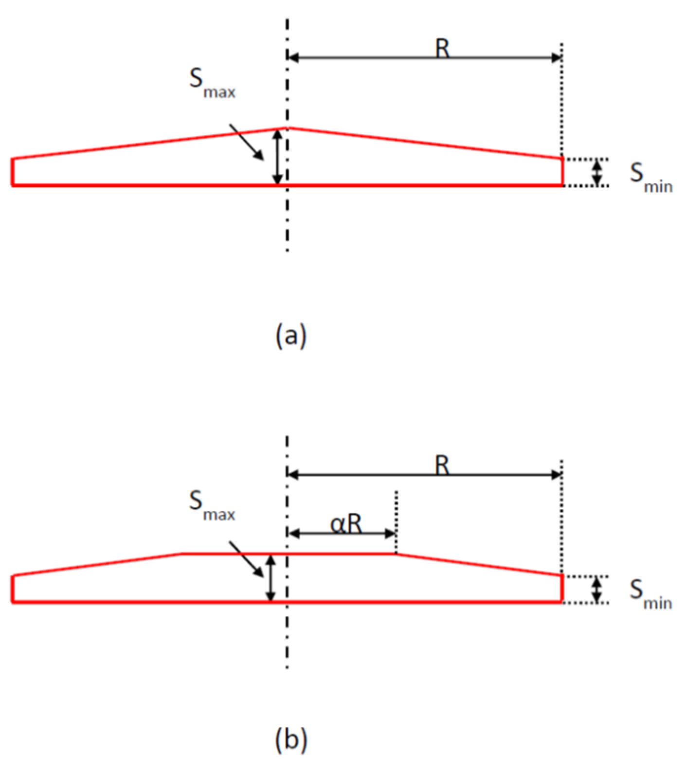
To manufacture the hemispherical shell via superplastic forming (SPF), the scheme of the circular blank, characterized by a simple conical thickness profile, is shown in
Figure 1a. The blank is characterized by three parameters: radius,
R; minimum blank thickness at the peripheral zone,
Smin; and maximum blank thickness at the axis of symmetry,
Smax. These latter two parameters are calculated as described below.
The initial volume of the blank,
V0, is equated to the final volume,
Vf, of the hemispherical shell, considering it characterized by a perfectly uniform thickness distribution of thickness
Smed. The volume of the blank consists of two parts: a cylindrical part (characterized by radius
R and height
Smin), V
1, and a conical part (characterized by a radius
R and a height S
max − S
min), V
2. Therefore:
The approximate final volume of the hemispherical shell is equal to
It should be noted that Equation (3) provides sufficient accuracy for thin shells where the thickness is negligible compared to the radius of curvature (t/R << 1).
Equating the blank volume to the final volume of the hemispherical shell yields
This relationship correlates Smin and Smax to Smed.
The previous treatment can be generalized to the case where the circular blank presents a truncated conical section (
Figure 1b). The geometry is governed by the dimensionless parameter (0 ≤≤ 1), which defines the radial extent of the constant-thickness region. Specifically, the central portion of the blank maintains a constant thickness, S
max, up to a radius of R, beyond which the thickness decreases linearly to S
min at the outer edge, R. In this case, Equation (4) transforms into
Equation (5) reduces to Equation (4) by α = 0.
If the initial profile of the blank were constant (S
0 = S
max = S
min), one would obtain
Setting S0 = 1, Smed = 0.5 mm is obtained.
The forming process of a hemispherical dome was simulated via FEM using the commercial software MSC-MARC 2005. The problem to be addressed involves axial symmetry, which can be schematized in a 2D environment using 4-node axisymmetric elements. In this way, four-node, isoparametric, quadrilateral elements adapted for axisymmetric applications were used. The elements were uniformly distributed along the sheet metal’s radius. A further simplification involves adopting only one half of the blank profile. The die geometry consists of a circular profile (radius
R = 50 mm) connected to the die edge by a small die entry radius (
r = 2 mm). The blank is constrained at the edge so as to avoid any sliding and thinning thereof. The process is assumed to occur under conditions of perfect lubrication. To ensure the material exhibits perfectly plastic behavior, the analysis required the use of the rigid-plastic flow formulation. Furthermore, the analysis did not require the use of an automatic mesh, thus maintaining the number of finite elements unchanged during the forming process simulation. Further details on the software adopted and mesh discretization are reported in [
28].
The material behavior is characterized by the power law expressed by the following equation [
1]:
where
is the equivalent strain rate, while
K (strength coefficient) and m (strain rate sensitivity index) are material constants.
This does not preclude the use of more articulated constitutive equations via FEM. Since this work aims to promote a blank design methodology for producing a hemispherical shell with uniform thickness, attention will be focused on the influence of the strain-rate sensitivity index, m, i.e., a parameter typical of the behavior of so-called superplastic materials.
The law used is typical of superplastic materials. Unlike m, the value of the constant K does not affect the final thickness profile of the hemispherical shell.
During the analysis, blanks with a truncated conical thickness profile will be considered. The different profiles employed are characterized by the parameter α previously defined. For comparison, keeping the material volume constant, the behavior of blanks characterized by a constant thickness profile will be considered.
As seen in
Figure 1b, the blank with a truncated conical section is characterized by a cylindrical element (of radius αR and height S
max) and by an element with a profile varying linearly from a height S
max to a height S
min. The equality of the blank volume to the hemispherical shell volume produces Equation (5), which correlates S
min and S
max to S
med. Once the parameter α is fixed, through a series of numerical simulations (conducted by fixing S
min in the range 0.80 ≤ S
min ≤ 1), the optimal blank profile is determined (i.e., that profile which guarantees equality between the thickness at the pole and the thickness at the edge of the produced hemispherical shell). While minimizing the global thickness variance is the ultimate goal, the condition of equal thickness at the pole and edge (S
p = S
e) was chosen as a robust and computationally efficient convergence criterion for the iterative search. Preliminary tests showed this condition effectively minimizes the thinning factor (A) for this specific geometry. This profile minimizes the thickness differences in the hemispherical shell.
3. Numerical Results
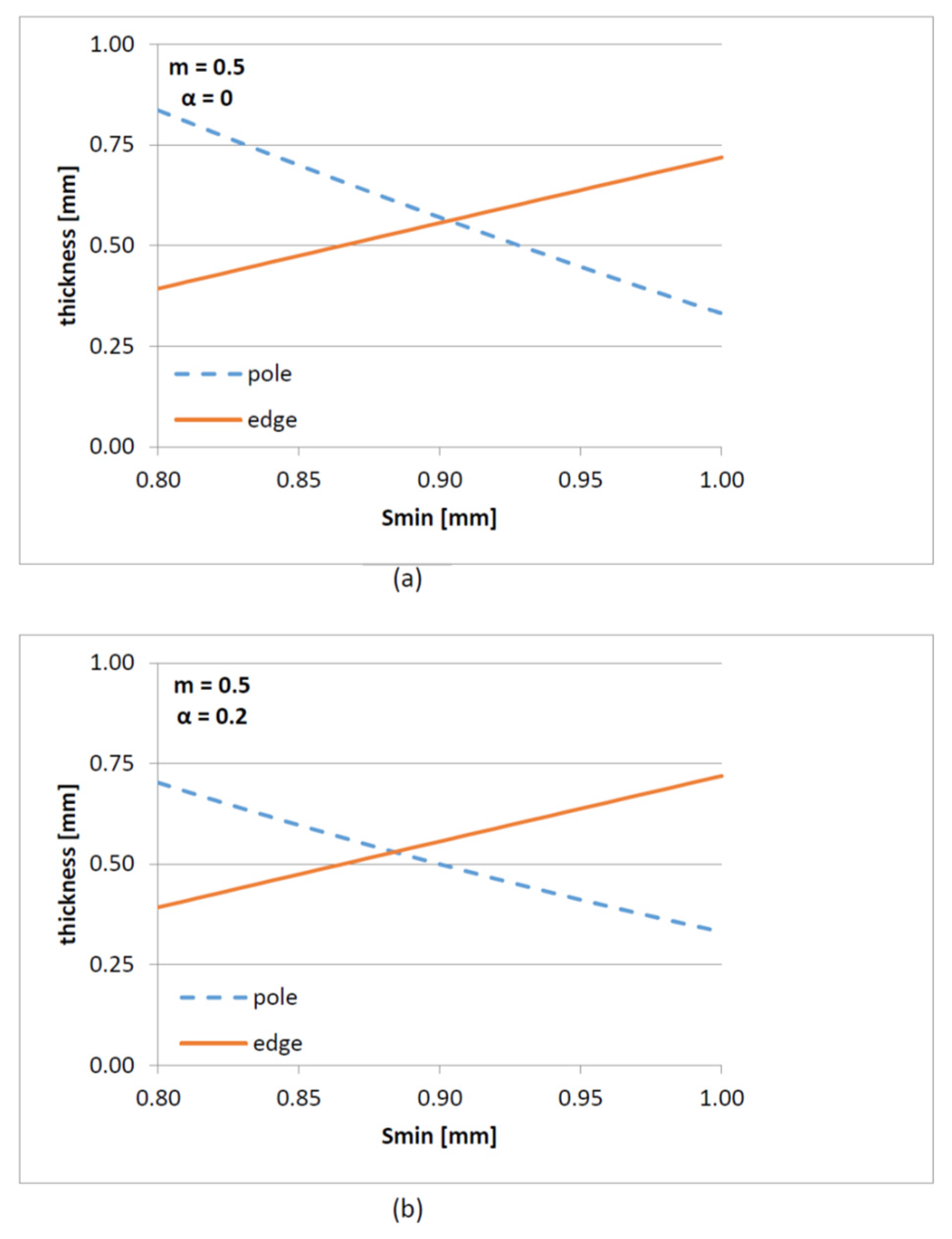
In FEM modeling, once the value of parameter α was defined, the blank geometry was prepared (fixing Smax and Smin), and several FEM simulations were conducted varying Smin in the range 0.80 ≤ Smin ≤ 1 (the value of Smax follows from Equation (5)). The results of these simulations lead to two curves, Sp-Smin and Se-Smin, which correlate, respectively, the thickness at the pole, Sp, and the thickness at the edge, Se, of the hemispherical shell with respect to the starting blank profile (identified by the thickness Smin).
Figure 2 shows the aforementioned curves for two cases of the blank profile (
α = 0 and
α = 0.2) and for a material with index m = 0.5 [
1].
Figure 2 shows that the two curves cross, corresponding to the optimal blank profile. Corresponding to the crossing point, the thickness at the pole of the hemispherical shell is equal to the thickness at the edge. Note that this value is different from 0.5 mm since there is not a perfectly uniform distribution of the final thicknesses of the hemispherical shell.
A further FEM simulation (carried out starting from the optimal blank profile identified in the previous step, corresponding to the crossing point between the curves S
p − S
min and S
e − S
min, that means S
p = S
e) allows evaluating the final thickness distribution of the obtained product. The criterion (S
p = S
e) serves as a highly effective geometric constraint for hemispherical shapes, ensuring that the two most critical thinning points are balanced.
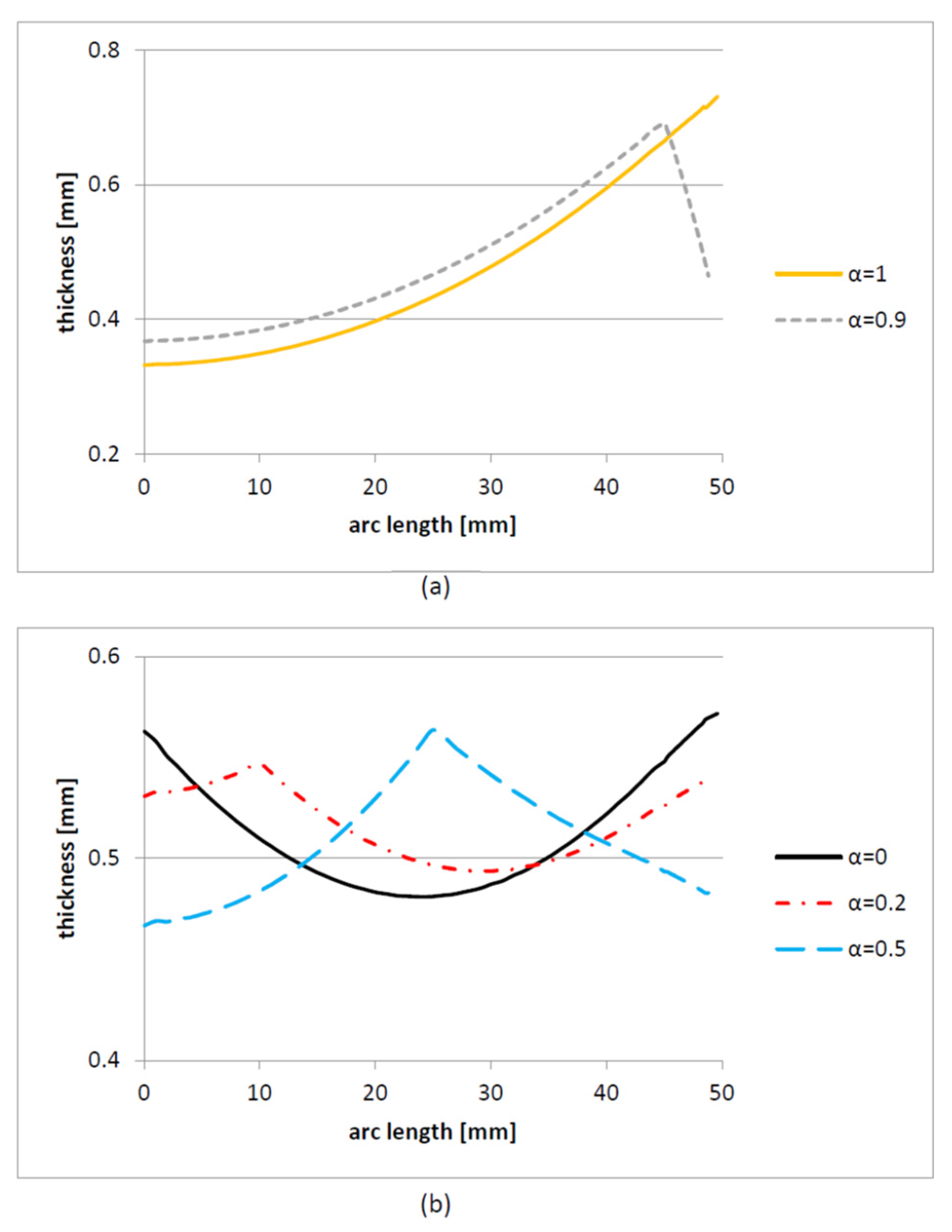
Figure 3 shows the results obtained by varying α from 0 to 1, considering only the optimal conditions.
Figure 3 shows only the results (a) for α = 0.9 and α = 1 and (b) for α = 0, α = 0.2, and α = 0.5.
It is clear that the final thickness profile obtained for α = 0.9 and α = 1 (i.e., a constant blank thickness of 1 mm), as represented in
Figure 3a, with thickness values outside the range of 0.4 to 0.6 mm, results in a highly non-uniform thickness distribution of the manufactured product. Furthermore, from
Figure 3b, it can be inferred that the most uniform thickness distribution corresponds to the value α = 0.2. This result is well represented in
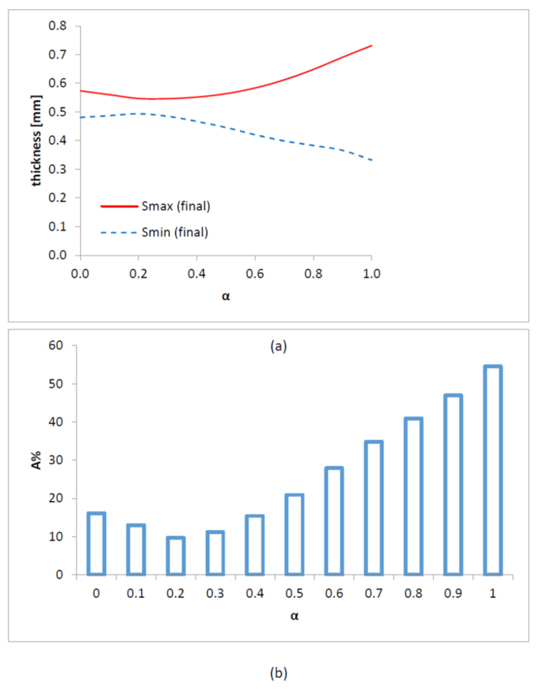
Figure 4. In
Figure 4a, the maximum (S
max) and minimum (S
min) final thicknesses of the hemispherical shell, obtained through FEM simulation, are represented under optimal blank profile conditions and for all values of α investigated (the material is characterized by a strain rate sensitivity index of m = 0.5).
Figure 4b shows the values of the thinning factor A calculated for each value of the parameter
α. From
Figure 4b, it can be inferred that the lowest reduction in thickness occurs for α = 0.2. This reduction is very significant as it goes from an A value of approximately 55% (if a constant thickness blank is used, i.e.,
α = 1) to a value of approximately 10% (if a blank characterized by
α = 0.2 is used).
Although manufacturing the variable blank adds a preliminary step, the structural integrity it provides allows for reduced starting sheet weight, potentially reducing material costs for mass production.
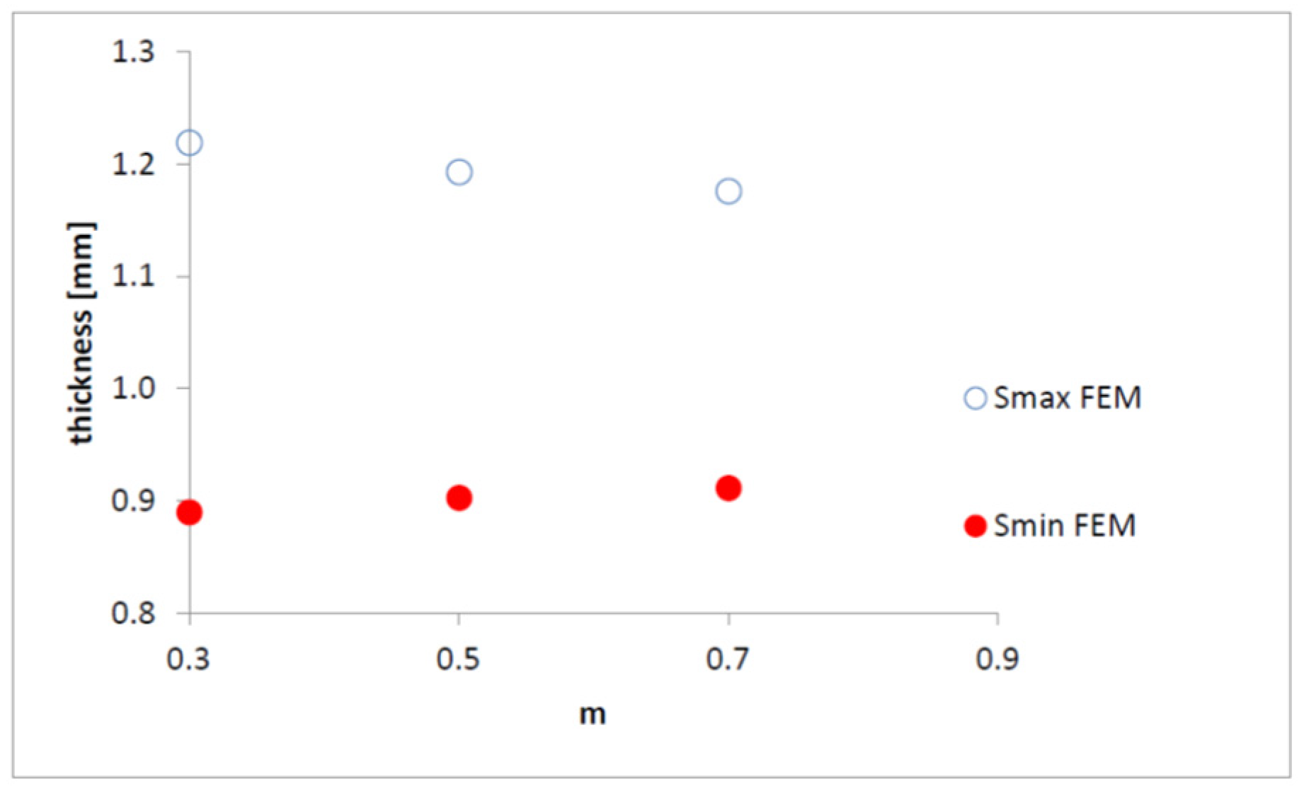
Figure 5 shows the FEM results for the optimal blank thicknesses (S
max and S
min) at α = 0, as the strain-rate sensitivity index, m, varies. From
Figure 5, it can be deduced that, in evaluating the optimal parameters of the blank profile (S
max and S
min), FEM modeling captures the influence of parameter m. In fact, via FEM, passing from m = 0.3 to m = 0.7, S
max reduces by approximately 3.5%, while S
min increases by approximately 2.4%.
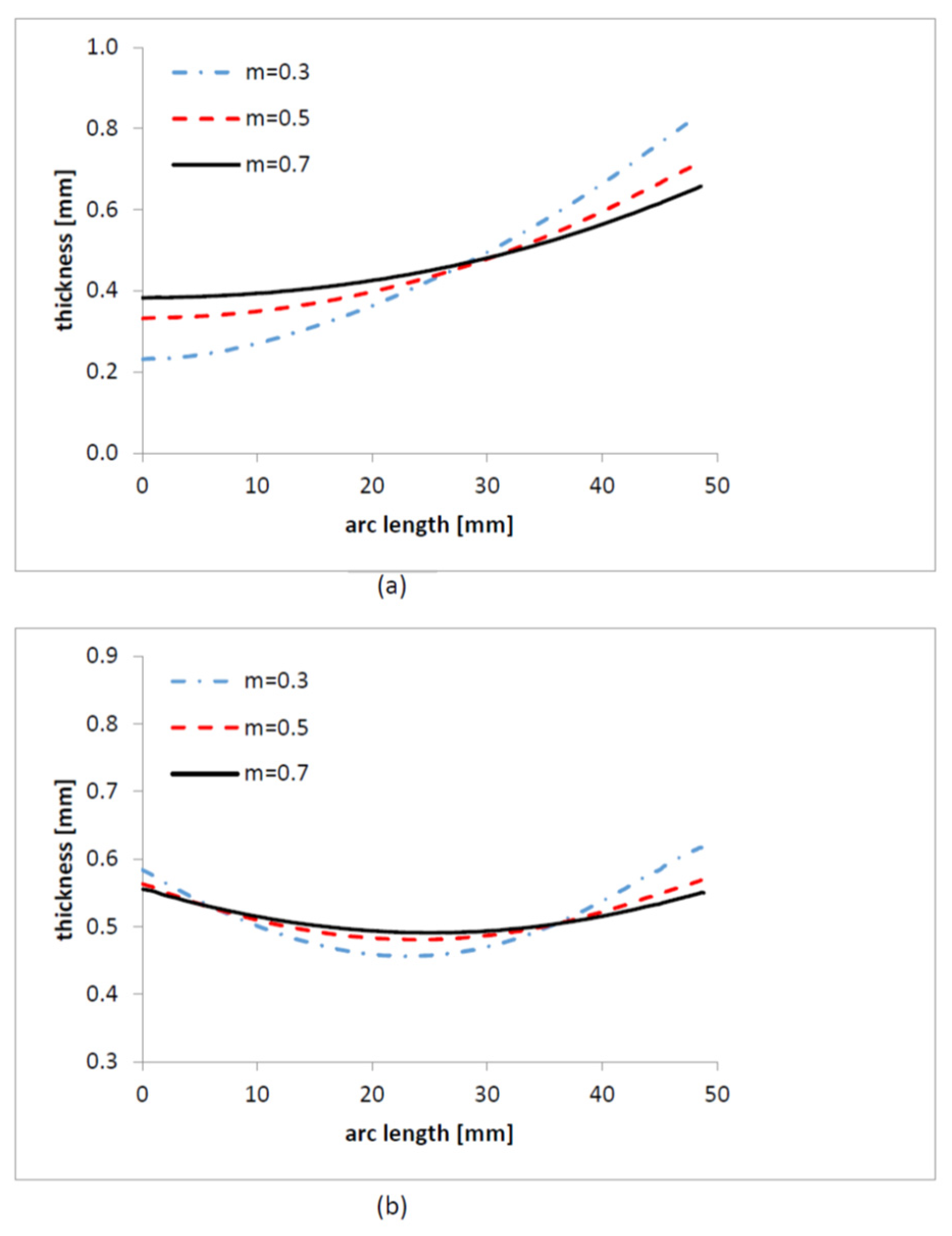
The dependence of the thickness distribution of a superplastic hemispherical shell on the parameter m is well documented in the literature [
23,
27,
29]. To validate this result,
Figure 6a shows the final thickness distribution of the hemispherical shell for different values of the strain-rate sensitivity index, m. The difference between maximum and minimum thicknesses expressed by the thinning factor A decreases as m increases. In particular, it ranges from approximately 72% for m = 0.3 to approximately 55% for m = 0.5, and up to approximately 43% for m = 0.7.
Figure 6b also shows the final thickness distributions for different values of m using the optimal blank profiles (the optimal condition shown applies only to the case α = 0). The value of the thinning factor A reduces with m passing to approximately 26% for m = 0.3, to approximately 16% for m = 0.5, and to approximately 12% for m = 0.7.
The numerical analysis reported in this work is based on the results obtained with a typical value of the strain-rate sensitivity index (m = 0.5) for superplastic materials. The aim of the work is to identify a truncated-conical blank that minimizes the thinning factor, A.
Figure 4 demonstrates that to achieve a minimum value of A (A = 9%), it is necessary to use a truncated-conical blank characterized by a value of α = 0.2. The value α = 0.2 was found to be independent of the numerical analysis value of m and of the die radius, R. Therefore, a value of R = 30 mm can also be used for the experimental geometry.
4. Experimental Verification
The numerical study was performed on a generic radius of R = 50 mm to establish general design rules. The experimental validation was conducted on an available die with a R of 30 mm. Since superplastic forming is governed by strain rates and geometric ratios (thickness/radius), the results are presented in terms of the normalized thickness and the thinning factor A, which are dimensionless, scalable parameters.
The experimental activity used the superplastic magnesium alloy AZ31 at 440 °C. This alloy has the following chemical composition by weight: Mg-3% Al-1% Zn.
The equipment used is located at the University of Cassino’s laboratory. Details regarding the equipment used are reported in [
28,
30].
In [
28], the authors obtained a hemispherical shell from both a constant-thickness blank and a variable-thickness blank that was not optimized for a conical profile section. Similarly, in [
30], a hemispherical shell was obtained starting from a non-optimized truncated conical blank. In the present work, however, a hemispherical shell was produced from both an optimized blank with a conical profile section (α = 0) and an optimized blank with a truncated conical profile (
α = 0.2), as shown in
Figure 7. The hemispherical shell was also obtained starting from a constant thickness blank (
α = 1) and of volume equal to that of the variable thickness blanks (see
Figure 7). The thicknesses of the produced shell were measured using a Prismo Vast MPS coordinate measuring machine from Zeiss
® (Oberkochen, Germany), as reported in [
28]. The thickness was measured at different points along the meridian. Due to fixture constraints, the shell’s extreme edge was not accessible. It is worth noting that this unmeasured peripheral region corresponds to the material constrained by the blank holder (i.e., the clamping zone). Since this area undergoes less significant superplastic deformation than the active dome, its exclusion from the analysis is considered acceptable and allows a focused evaluation of the useful component’s uniformity. It was possible to identify the optimal values, S
max and S
min, for the variable-thickness blanks, and the thickness value for the constant-thickness blank.
Table 1 reports the thickness values measured at the specified distances from the shell’s axis of symmetry. The results presented in
Table 1 were subsequently commented on, and the values of A were obtained from them. The paragraph concluded by identifying the blank with a truncated-conical profile (α = 0.2) as the optimal one (the measured value of A is the smallest value). From
Table 1, it can be deduced that the thicknesses of the shell obtained starting from a constant thickness blank thin out corresponding to the axis of symmetry of the hemispherical shell. The minimum and maximum thicknesses measured on the shell are, respectively, (S
f)
min = 0.305 mm and (S
f)
max = 0.437 mm.
From the same table, it can be deduced that, starting from a conical blank, one has (Sf)min = 0.440 mm in the region between 15 and 25 mm from the axis of symmetry, and (Sf)max = 0.510 mm corresponding to the axis of symmetry. The shell, obtained from a blank characterized by a truncated conical profile of type α = 0.2, presents a value of (Sf)min = 0.452 mm at a distance of 25 mm from the axis of symmetry, and (Sf)max = 0.492 mm near the axis of symmetry.
The minimum and maximum thickness data corresponding to the three situations addressed allow determining the thinning factor A (a parameter that quantifies the uniformity of shell thicknesses). From the definition of the thinning factor A (Equation (1)), it is obtained that it is possible to produce a hemispherical shell starting from a constant thickness blank with the thinning factor A approximately 30%. The thinning factor A reduces to approximately 14% when a variable-thickness blank with a conical profile is used. Finally, the value of the thinning factor A reduces further (A approximately 9%) if a blank with a truncated conical profile with α = 0.2 is used.