Article

A Concept of an Emergency Braking Device for a Mine Suspended Monorail Travelling at an Increased Speed


KOMAG Institute of Mining Technology, Pszczyńska 37, 44-101 Gliwice, Poland
*
Author to whom correspondence should be addressed.
Appl. Sci. 2026, 16(3), 1338; https://doi.org/10.3390/app16031338
Submission received: 12 December 2025 / Revised: 9 January 2026 / Accepted: 26 January 2026 / Published: 28 January 2026
(This article belongs to the Special Issue Advances in Coal Mining Technologies)

Abstract

Increasing the permissible travel speed of suspended monorails in underground mines improves the efficiency and profitability of hard coal mining. However, increasing the maximum speed requires addressing a number of issues affecting the safety of the crew and the mine infrastructure. The concept of a new emergency braking device presented in this article is intended to protect against excessive temperature increases on friction surfaces during braking. The article presents the results of preliminary numerical simulations, the purpose of which was to calculate the temperature of a wet multi-plate brake, its propagation, and verify the condition for not exceeding the maximum permissible temperature of external surfaces in contact with a potentially explosive atmosphere.

1. Introduction

Efficiency of underground transport methods is one of the key aspects ensuring smooth mining processes and productivity in underground hard coal mines [1,2]. This article is limited to auxiliary transport methods related to transporting crews to the workplace. Development of these machines through the use of increasingly new generations of drive motors, state-of-the-art designs of support sets, and methods of suspending routes has revolutionised the flexibility of transport operations, enabling them to travel on the routes with inclinations of up to 30°, which are not possible for the conventional floor-mounted systems [1,3,4,5]. However, it should be noted that the strategic consolidation of mining operations and depletion of easily accessible coal deposits have significantly extended the distance between the shaft and the active mining faces [1,2]. This route extension has created a significant logistical and economic challenge related to the miners’ travel time to the workplace. This time is determined by the maximum permissible speed of the suspended monorails during crew movement. This speed determines the travel time, which is included in the miner’s working time but is not effective work time [1,2,6].
In Polish and Slovenian underground mines, current regulations limit the maximum permissible speed of suspended monorails for personnel movement to 2 m/s, while German regulations allow speeds of up to 3 m/s [1,7]. The economic impact of these time losses is significant and well-documented. Tests at İMBAT Mining Co. in Manisa, Turkey, showed that reducing travel time by just 15 min each way resulted in an increase in mining productivity by 1606.95 tons per day [2,8]. Therefore, there is growing international interest in increasing the permissible speed of suspended monorails for moving personnel, which would directly extend operating time and improve mining efficiency [1,7].
Besides the speed, tests are underway to introduce electric drives to replace diesel drives, with the goal of reducing the exhaust emissions in underground mines [1,7,9]. At the same time, state-of-the-art control systems using innovative mechatronic solutions are being implemented in monorail designs [1,10,11,12,13]. These technological advances create a foundation upon which increased travel speeds can be safely implemented [1,11,14].
While increasing travel speeds brings obvious economic benefits, it also poses significant safety challenges, especially during emergency braking [1,7]. The kinetic energy of a moving monorail increases proportionally to the square of its speed, meaning that emergency braking at high speeds generates significantly greater forces and g-forces than those experienced at current operating speeds [1,7].
According to Polish mining regulations, deceleration when moving personnel during emergency braking must not exceed 10 m/s2, while Slovenian regulations set a similar limit of 9.81 m/s2. These limits are intended to minimise the risk of injury to operators and passengers, because excessive deceleration can cause uncontrolled movement of personnel within cabins, potentially resulting in injuries from impact with the cabin structure or ejection from seats [1,7,15,16,17]. To address the problem of deceleration during emergency braking, the authors conducted extensive tests using virtual prototyping methods, such as kinematic and dynamic simulations of multibody systems (MBSs) and the finite element method (FEM). The analysed numerical models were validated based on the results of pioneering in situ and bench measurements taken by the authors as part of various testing projects. Research work using the computational models of suspended monorails travelling at speeds up to 5 m/s showed that conventional emergency braking systems can generate decelerations significantly exceeding regulatory limits under certain conditions, particularly when braking empty or lightly loaded trains on levelled or inclined routes. On the other hand, on routes with steep downward gradients (30° gradient), standard braking forces may be insufficient to stop a train within the required braking distances [1,7,18,19,20,21,22,23].
One of the tests during the virtual prototyping process involved simulations with virtual anthropomorphic models of HYBRID III test devices (ATDs)—analogous to dummies used in car safety tests—to estimate the risk of injury during emergency braking or collisions. These tests calculated Head Injury Index (HIC) values, demonstrating that at a speed of 5 m/s, operators without seat belts are at significantly higher risk of serious or fatal head injuries in emergency situations. The results of these studies led to recommendations for mandatory passive safety features, including seat belts and headrests, in operator and passenger cabins of high-speed monorails [16,24].
Another solution to the braking management problem has emerged as sequential emergency braking algorithms. Unlike conventional systems that immediately release maximum braking force, sequential braking divides the total braking force into two stages. At the first stage, a reduced braking force (typically 40–50% of maximum) is applied, after which the system monitors the actual braking. If the measured deceleration falls below a specified threshold after a specified time (typically 0.3–0.5 s), a second braking stage—which may include multi-disc brakes integrated with the gear drives—is activated to provide additional braking force. This adaptive approach allows the braking system to modulate forces based on actual operating conditions (train load, route gradient, etc.), preventing excessive deceleration while ensuring adequate braking capacity [25]. Numerical simulations of sequential braking systems have demonstrated their excellent performance in various operational scenarios. By analysing the impact of changes in braking force parameters, delays between braking stages, and braking force distribution coefficients, the researchers identified configurations that maintain deceleration within acceptable limits while minimising braking distance. Tests of braking algorithm parameters have shown that the sequential system can effectively manage emergency braking on horizontal and inclined sections of the route [26,27].
It should be remembered that, in addition to the direct impact on personnel, emergency braking at high speeds causes the suspended monorail line and its supporting infrastructure to be subjected to dynamic overloads that may exceed the permissible forces defined by law. The suspended line, constructed of I155 or I140 V steel rails suspended from the curves of the flexible pavement support using chains and slings, is not a rigid structure; individual rails can move relative to each other at the joints, and the entire line can undergo longitudinal and vertical displacements under the influence of dynamic loads. Furthermore, to ensure stability, the suspended line must always be stabilised on curves and gradients, and if necessary, stabilisation of straight sections is recommended at least every 100 m [5,10,20,28,29,30,31,32]. Studies have shown that during emergency braking at a speed of 5 m/s, the forces acting on the roadway suspensions can increase by 52–65% compared to braking at 1 m/s, with the diagonal stabilising stays subject to the greatest stress. These forces are transferred via the suspension chains to the steel arches of the roadway support, which in Polish mines can be loaded with a maximum force of 40 kN per arch. Exceeding these limits can cause deformation or damage to the arch, which can lead to roadway collapse: a catastrophic event that endangers personnel and disrupts mine operations [1,2,5,7,10,20,30]. The method of suspension and stabilisation of the roadway significantly influences the magnitude and distribution of dynamic forces during emergency braking. Comparative numerical simulations of seven different suspension configurations—from simple vertical suspensions to complex systems incorporating diagonal suspensions and flexible side stays with vibration damping elements—demonstrated significant differences in maximum suspension forces, track displacements, and operator decelerations. The results showed that the introduction of flexible side stays reduced the maximum suspension forces by approximately 27.5% compared to a purely vertical suspension [5,10,28,29,33]. These results highlight the need for evidence-based guidelines for high-speed track installations that ensure both personnel safety and infrastructure integrity. Pioneering tests conducted on-site, at specialised test rigs, and in underground mines provided empirical confirmation of these theoretical predictions. Special force transducers, mechanically integrated with the suspension systems by replacing three chain links, enabled real-time measurement of suspension forces during actual monorail operation [1,5,7,23,28,29,33,34].
Readers can find more details on the solutions discussed in relation to increasing the speed limit in previous articles by the authors cited in the references.
An equally important safety issue that emerged from high-speed braking research concerns the thermal behaviour of braking system components. During emergency braking, kinetic energy is converted into thermal energy at the interface between the brake shoes and the rail. Tests conducted by the authors in collaboration with the Central Mining Institute (GIG) in Poland, using high-speed thermal imaging cameras and contact-based temperature measurement methods with a sampling rate of 1200 Hz, documented brake shoe surface temperatures during the emergency braking at various speeds [26,35,36,37]. The results indicate that single-shoe configurations can generate surface temperatures exceeding 150 °C during emergency braking at 5 m/s, with maximum recorded temperatures reaching 171.3 °C. In several tests, mechanical sparking—visible as bright spots on thermal images—was observed at the brake shoe–rail interface, caused by localised material ablation and friction-induced glow. These transient thermal phenomena pose a serious safety risk in underground coal mines, where methane and coal dust create a potentially explosive atmosphere. The test stand consisted of a 3 m diameter flywheel with an 8 mm thick toothed ring, enabling the braking system to be tested at different kinetic energies by adding or removing steel sheets from the frame [13,30,35].
The ATEX Directive (European Directive 2014/34/EU) and the harmonised standard PN-EN ISO 80079-36:2016 [38] specify the maximum permissible surface temperatures of equipment used in explosive atmospheres to prevent ignition of flammable gases or dust clouds. For equipment operating in underground coal mines where methane is present, classified as having explosion hazard levels a, b, or c (methane concentration potentially exceeding 0.5%, 1.0%, or more, respectively), non-electrical mechanical equipment must not exceed a surface temperature of 150 °C in the presence of accumulated coal dust. The observed exceedance of this temperature limit during high-speed emergency braking using single-shoe brakes indicates that conventional braking systems may not meet ATEX requirements during high-speed operation [38,39,40]. Numerical simulations using finite element thermal analysis (FEM) provided additional insight into this phenomenon. Time-domain thermal calculations, assuming a thermal conductivity of 40 W/(m·K) and a specific heat capacity of 444 J/(kg·K) for steel, showed that short-term heating of the friction surface (approximately 0.14 s), even to temperatures exceeding 200 °C, does not cause significant heat transfer into the brake pad material, nor does it cause a sustained temperature increase that would compromise normal operation. Furthermore, bench tests measuring internal brake shoe temperatures using built-in thermocouples confirmed that repeated braking at 5 m/s with intervals of several minutes between cycles causes only a small (1–2 °C) cumulative temperature increase, indicating that braking solely in emergency situations does not cause problematic heat buildup. However, transient surface temperature fluctuations during each braking applications remain a compliance issue that needs to be addressed through modified braking system design [1,26,35,37,39]. Potential solutions identified by tests include increasing the effective friction surface area by using dual pairs of brake shoes (which has been shown to reduce the maximum temperature below 150 °C even at a speed of 5 m/s and achieve an average maximum braking force of 99.4 kN with a kinetic energy of 6273 J); implementing active brake component cooling the systems; or enclosing the friction surfaces in oil bath housings for more efficient heat dissipation. Use of dual brake pads allowed for the shortest braking distance while maintaining surface temperature within acceptable limits. Each of these solutions has its advantages and technical challenges, which must be assessed in the context of the overall system design and operational requirements [1]. The above discussion has shown that conventional emergency braking devices, while suitable for current operating speeds of 2 m/s, exhibit significant limitations when used on suspended monorails operating at 3–5 m/s [1,7]. In particular, traditional systems cannot simultaneously meet three interrelated safety requirements:
  • Crew protection: Preventing excessive deceleration forces (>10 m/s2) that can cause injury to operators and passengers, requiring integration with advanced control algorithms and adaptive force modulation, as demonstrated in the HYBRID III ATD analyses [16,17,24,33,34];
  • Route and support protection: Limiting dynamic forces transferred to the route suspensions and arch supports to prevent infrastructure damage, which requires careful coordination with optimised route stabilisation systems and limiting each suspension force below the maximum working load of 40 kN [2,5,7,10,20,28,30,31];
  • ATEX compliance: Maintaining the surface temperature of brake components below 150 °C to eliminate the risk of methane and coal dust ignition in explosive atmospheres, in accordance with the requirements of European standards (PN-EN ISO 80079-36:2016 [38]) and Polish mining regulations (PN-G 46860:2011 [15]) [13,30,35,39,40].
The main goal of these tests is to develop and virtually validate a conceptual design for an innovative emergency braking device, specially designed to address these shortcomings. The author work presented in this article focuses on temperature issues, how to dissipate it, and ensuring compliance with the ATEX standard [1,38,39,41].
This article presents a new design for a multi-disc brake, in which the braking plates are enclosed and immersed in an oil bath. Braking occurs through frictional engagement of the braking wheels with the rail web. The article presents both the concept of the new braking device and the results of numerical simulations performed to confirm lack of dangerous heating of the device surface, even during braking from a speed of 9 m/s.

2. Materials and Methods

2.1. Concept of the Geometric Form of the New Emergency Braking Device for Suspended Monorail

The implementation of high-speed underground railways necessitates the development of a new type of emergency braking device. Its main feature should be the elimination of open friction surfaces, which can pose an obstacle when approving individual components of the suspended monorail for use, particularly for high-speed operation.
The suggested emergency braking device for high-speed overhead monorails for passenger transport is derived from the solutions currently used in toothed drive and braking systems. Its main component is a set of multi-disc brakes immersed in an oil bath. The entire system is enclosed in a compact enclosure. A friction wheel, whose lateral friction surface presses against the rail web, is the actuator. This surface can be manufactured in one of two variants: (1) elastomer; (2) metal with knurling (straight or cross). Isolation of the hottest friction surfaces from a potentially explosive atmosphere is the innovative feature of the proposed solution. While multi-disc brakes are used in suspended monorail systems, they are integrated with the drive system and cannot be used as a standalone emergency braking device.
The above solution significantly improves operational safety by achieving the following:
  • eliminating open surfaces that can heat up to temperatures exceeding 150 °C;
  • reducing dynamic overloads in the joints and suspensions of the suspended monorail track, resulting from the movement of brake pads compressed between two adjacent rails.
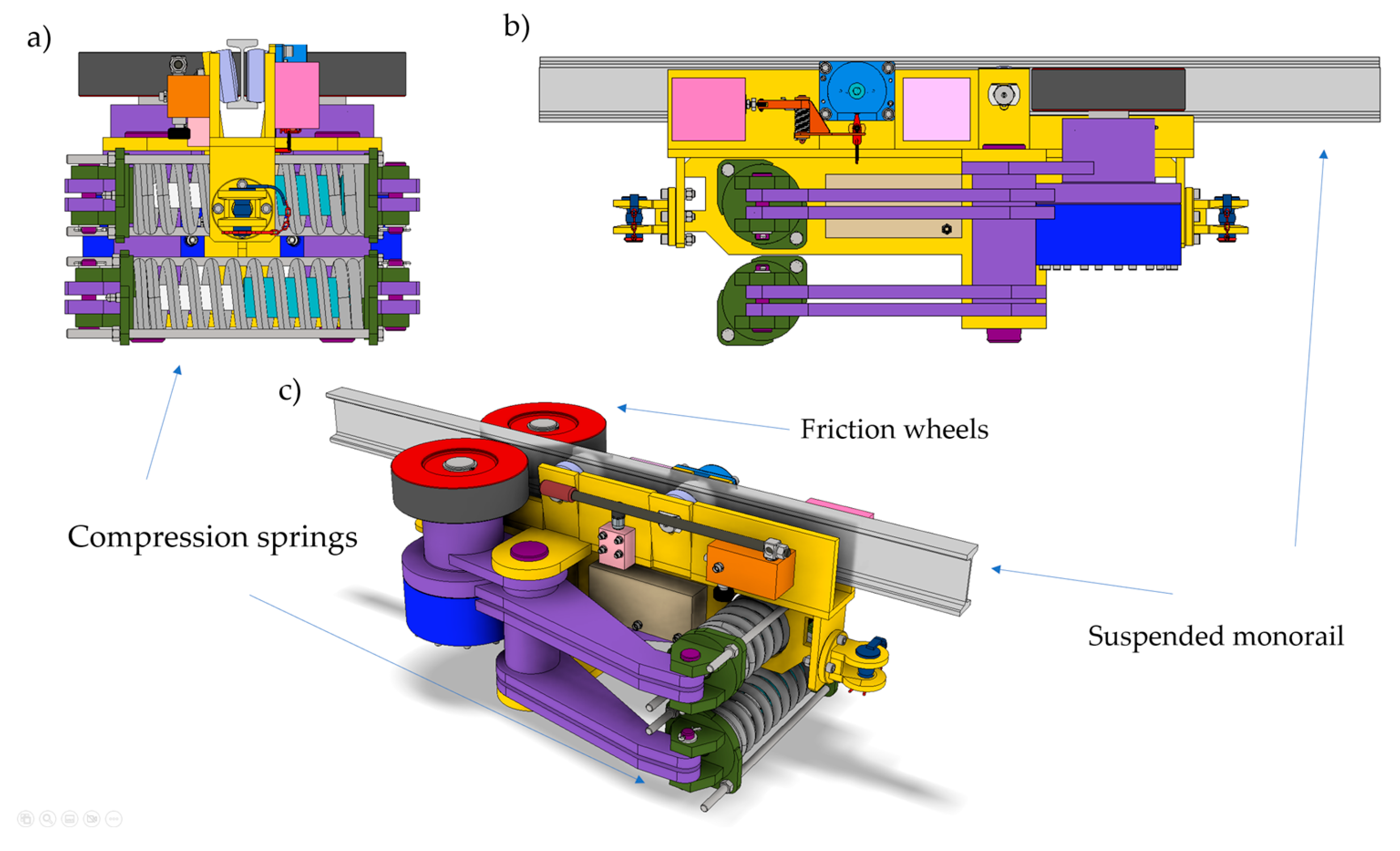
Figure 1 shows the emergency braking device with the emergency braking mechanism of a suspended monorail, in orthogonal and perspective views.
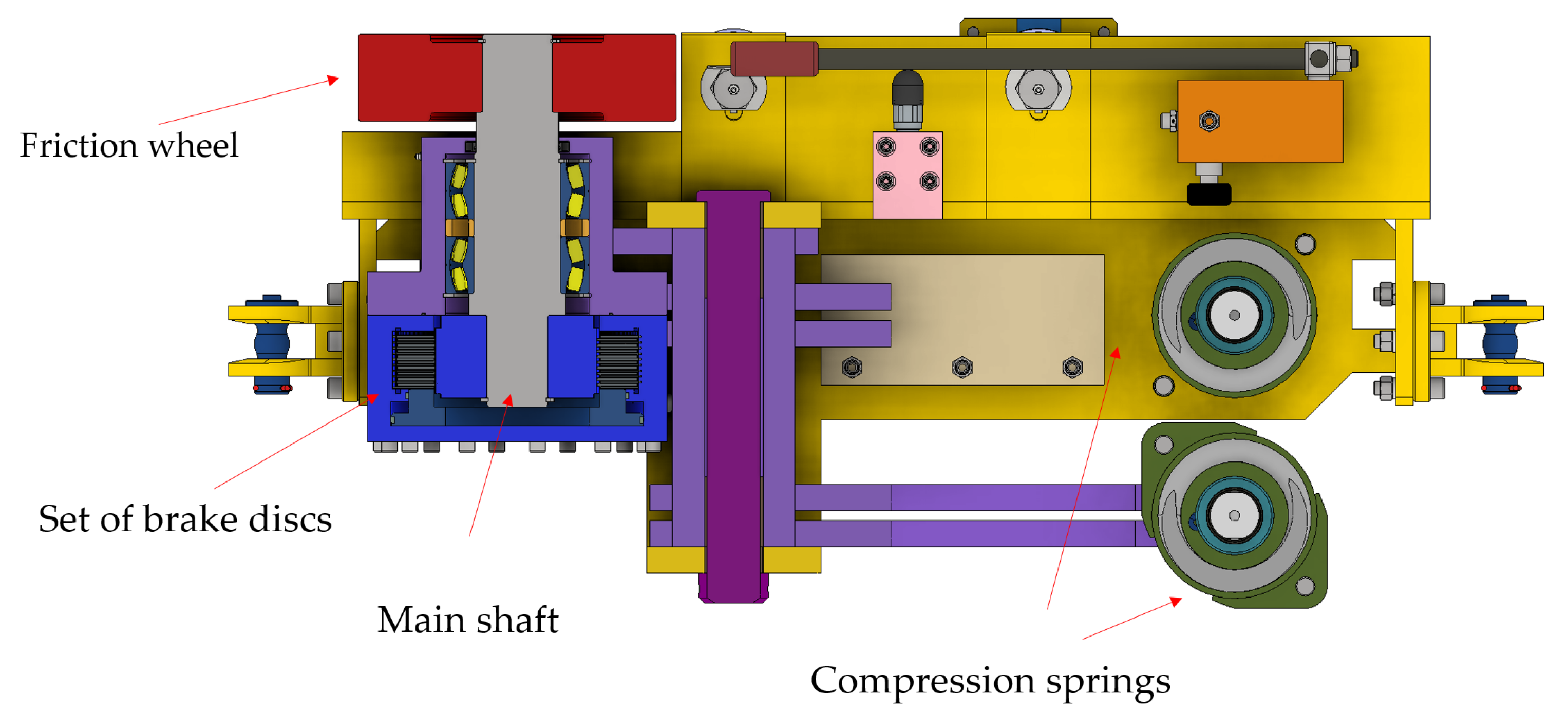
The emergency braking device moves on four bearing-mounted rollers that roll on the lower flanges of the suspended rail’s I-beam. The emergency braking mechanism consists of two symmetrical, two-armed brake levers that operate on a scissor-like principle in a plane parallel to the lower flanges of the suspended rail. The longer lever arms are spread apart at their ends by brake springs. Braking wheels are pivotally attached to the ends of the shorter lever arms and pressed against the rail web. Lengths of the arms as well as the spring pressure force are selected so that the force exerted by them on the braking wheels against the rail web ensures frictional engagement at maximum braking force. Figure 2 shows a longitudinal cross-section through the body of the emergency braking device.
The brake enclosure contains a stack of alternating plates, the outer plates meshing with the inner surface of the enclosure and the inner plates meshing with the outer surface of the hub. The brake braking torque is generated by the piston pressing against the stack of plates, and is implemented by a set of springs. The plates and bearings are immersed in oil. The kinetic energy of the suspended high-speed railway transport unit is converted into heat by friction between the outer and inner plates, which is absorbed by the oil and the emergency braking device enclosure.

2.2. Virtual Prototyping

The main objective of the numerical calculations is to determine the kinetic energy profile, including the maximum kinetic energy value and the time it takes for the transport unit to dissipate (MBS environment). In turn, the influence of heat flux and cooling intensity was analysed using the Altair Simlab/Optistruct ver. 2024 finite element method (FEM) software environment to determine changes in the brake pad temperature and its propagation towards the external surfaces of the emergency braking device housing. Four variants were analysed, differing in the maximum speed achieved by the transport unit.

2.2.1. Computational Model Developed in a Software Environment Based on the Kinematics and Dynamics of Multibody Systems (MBSs)

The MBS model was developed to calculate the kinetic energy of the transport unit in relation to the emergency braking process at various maximum monorail speeds. This model consists of 39 rigid bodies connected by geometric constraints and contact models defined between selected bodies. The model was developed on the basis of a geometric model, by introducing simplifications related to the removal of small components (such as screws, washers, seals, etc.) that do not affect kinematics and dynamics. The behaviour of 39 independent solids allows for a complete representation of the work and flow of forces and moments during emergency braking. The model consisted of two main components: the brake bogie and a body assigned a concentrated mass of 15 tons, corresponding to the mass of the transport unit. A geometric constraint was applied to the body representing the mass of the monorail, restricting its 5 degrees of freedom, leaving only the possibility of translation parallel to the axis of the track along which the brake bogie was travelling. The MBS model of the device is shown in Figure 3.
At the first phase of the simulation, the transport unit was accelerated to maximum speed. This was achieved by activating the force vectors pressing the friction wheels against the rail web and activating the driving torque vectors applied to the friction wheels. After reaching maximum speed, the driving torque vectors were deactivated, while the force vectors compressing the multi-disc brake plates were activated. This generated a braking force that, through frictional engagement of the friction wheels with the rail, brought the transport set to a stop. Once the set stopped, the simulation ended.
Boundary conditions adopted in the MBS model were as follows:
  • the force pressing the friction wheels onto the rail web, applied at the end of the brake lever (arm), was 4 × 10,000 N;
  • the compression force of the plates in the multi-disc brake was 75,000 N;
  • the friction coefficient between the plates in the multi-disc brake was 0.9;
  • the friction coefficient between the friction wheel and the rail was 0.6.
The purpose of the developed model was to estimate the kinetic energy values at various braking speeds of a suspended monorail. During the simulation, the loading method of the monorail route, the loads on individual suspension slings, and other important aspects necessary for the design and approval of the transport set were not taken into account. Level of detail in the presented model was intentionally simplified to provide the simplest possible estimate of the amount of kinetic energy that will be converted into thermal energy flow in the multi-disc brake. This value serves as input data for numerical FEM thermal analyses conducted using a detailed model of the multi-disc brake. Based on the results of the thermal analyses, it will be possible to correct the parameters of the multi-disc brake, which will enable it to operate safely (by preventing excessively high external surface temperatures). Depending on the needs, the contact force of the friction wheels and the design of the friction wheels themselves can also be modified. Therefore, the boundary condition values adopted in the MBS model are the base values that will be selected and modified in subsequent stages of the design and construction process.

2.2.2. Computational Model Developed in a Finite Element Method-Based Software Environment

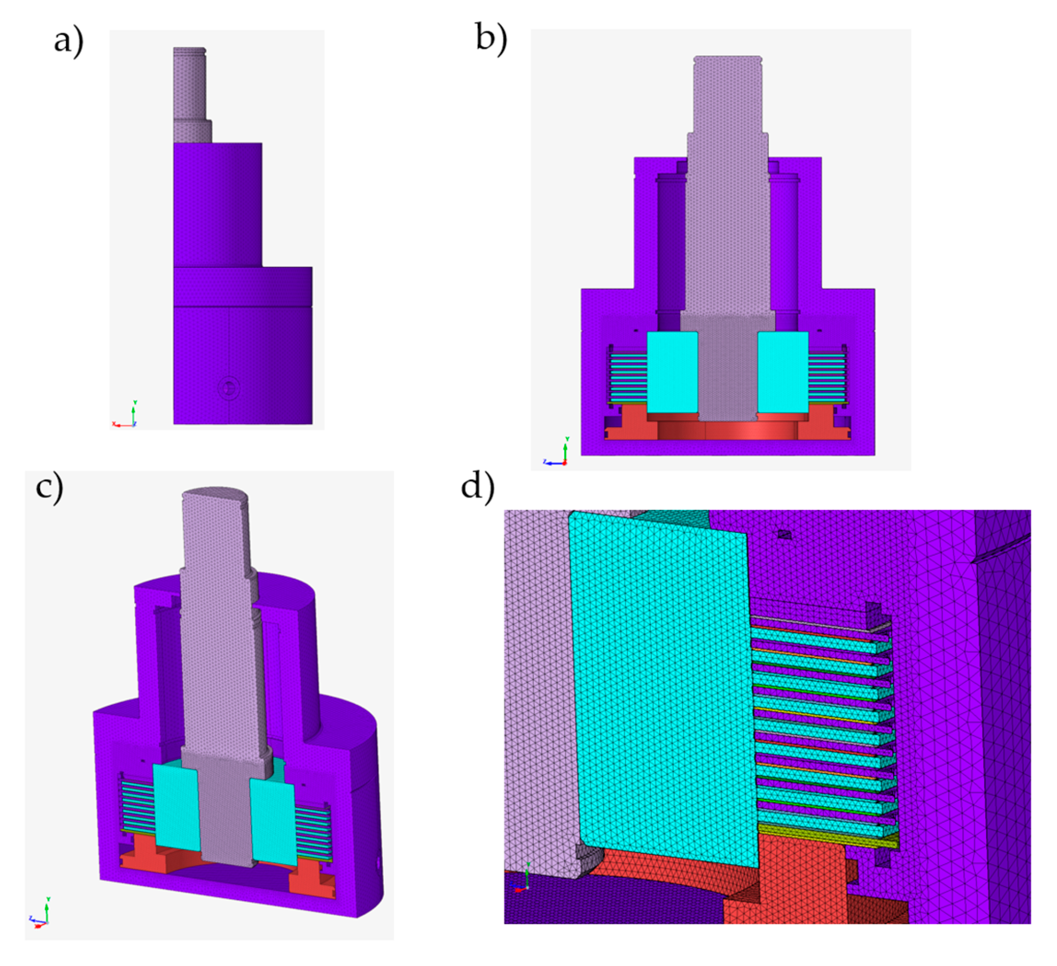
Based on the spatial geometric model, the FEM computational model was created in the Altair Simlab/Optistruct ver. 2024 software environment. Time-varying thermal calculations were performed for the multi-disc brake enclosure of the emergency braking device. In order to speed up the calculation process while maintaining high quality of the results, the symmetry of geometric features was used (the calculations included half of the body and internal parts), as shown in Figure 4.
A 3D geometric model of the multi-disc brake was discretized using second-order tetrahedral solid elements (TET10). These elements ensure high accuracy of calculation results with acceptable calculation time. Computational model consists of 3.8 million nodes and 2.1 million of TET10.
The following two models of materials were defined as follows:
  • Steel (enclosure, shaft, inner and outer brake discs):
    • Density, 7850 kg/m3;
    • Thermal conductivity, 49.81 W/(m·K);
    • Heat capacity 500 J/(kg·K).
  • Friction of lining (attached to the two outer sides of the non-rotating brake discs):
    • Density, 1570 kg/m3;
    • Thermal conductivity, 0.4 W/(m·K);
    • Heat capacity 530 J/(kg·K).
The following boundary conditions were defined as follows:
  • Forced convection on the surface of oil-wetted components, 870 W/(m2·K);
  • Free convection on the external surfaces of the emergency braking device housing, 20 W/(m2·K);
  • Initial temperature and temperature during the simulation process: 293.15 K (20 °C);
  • TIE contacts between the brake discs and linings, as well as between the brake discs and the shaft, and between the brake discs and the brake assembly enclosure;
  • Simulation time: 5 s.
Four time-varying thermal calculations were performed for the heating and cooling the brake discs and linings, differing in the intensity and duration of the heat flux. These were proportional to the changes in the time taken for the transport unit to dissipate kinetic energy. Time taken to reach the maximum value and then return to zero for the heat flux was assumed to be 0.15 s.
One of the simplifications used in the FEM calculation model was a constant convection coefficient on the brake disc surfaces. This is related to emergency braking situations; this phenomenon is short-lived, therefore there is no need to introduce forced circulation of cooling oil and radiators. All brake discs are immersed in oil. The primary goal of the calculations was to assess the safety status associated with the use of the emergency braking device, i.e., ensuring that the permissible temperature on its external surfaces, which are in contact with a potentially explosive atmosphere, is not exceeded.
Due to the nature of emergency braking, this phenomenon is short-lived, therefore there is no need to introduce forced circulation of cooling oil and radiators.

3. Results

3.1. Results of MBS Simulation

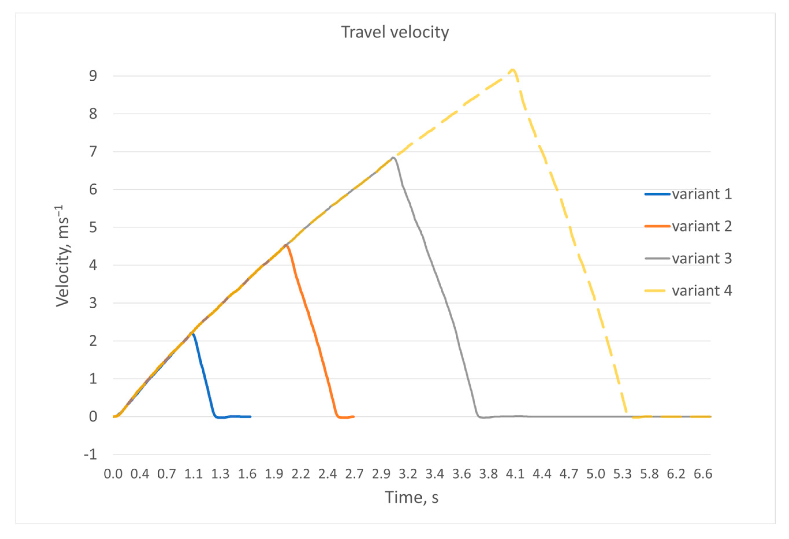
Emergency braking of four variants of speed of a suspended mine monorail were simulated. Variant 1 was the baseline variant, referring to current Polish mining regulations, which determine the maximum permissible speed of the transport unit when carrying people. The maximum permissible speed is 2 ms−1. Taking into account the inertia of the control system and the actuators of the emergency braking systems, after activation of the emergency braking system, there is a certain increase in the speed of the accelerating unit, particularly when travelling on a slope. Therefore, in variant 1, the maximum speed of the unit was achieved at 2.2 ms−1. In subsequent variants, the travel speed at which emergency braking was activated increased. The maximum recorded speeds of the set were as follows: in variant 2–4.5 ms−1, in variant 3–6.8 ms−1, in variant 4–9.1 ms−1. The curves of the speed during the simulation of each variant are presented in Figure 5.
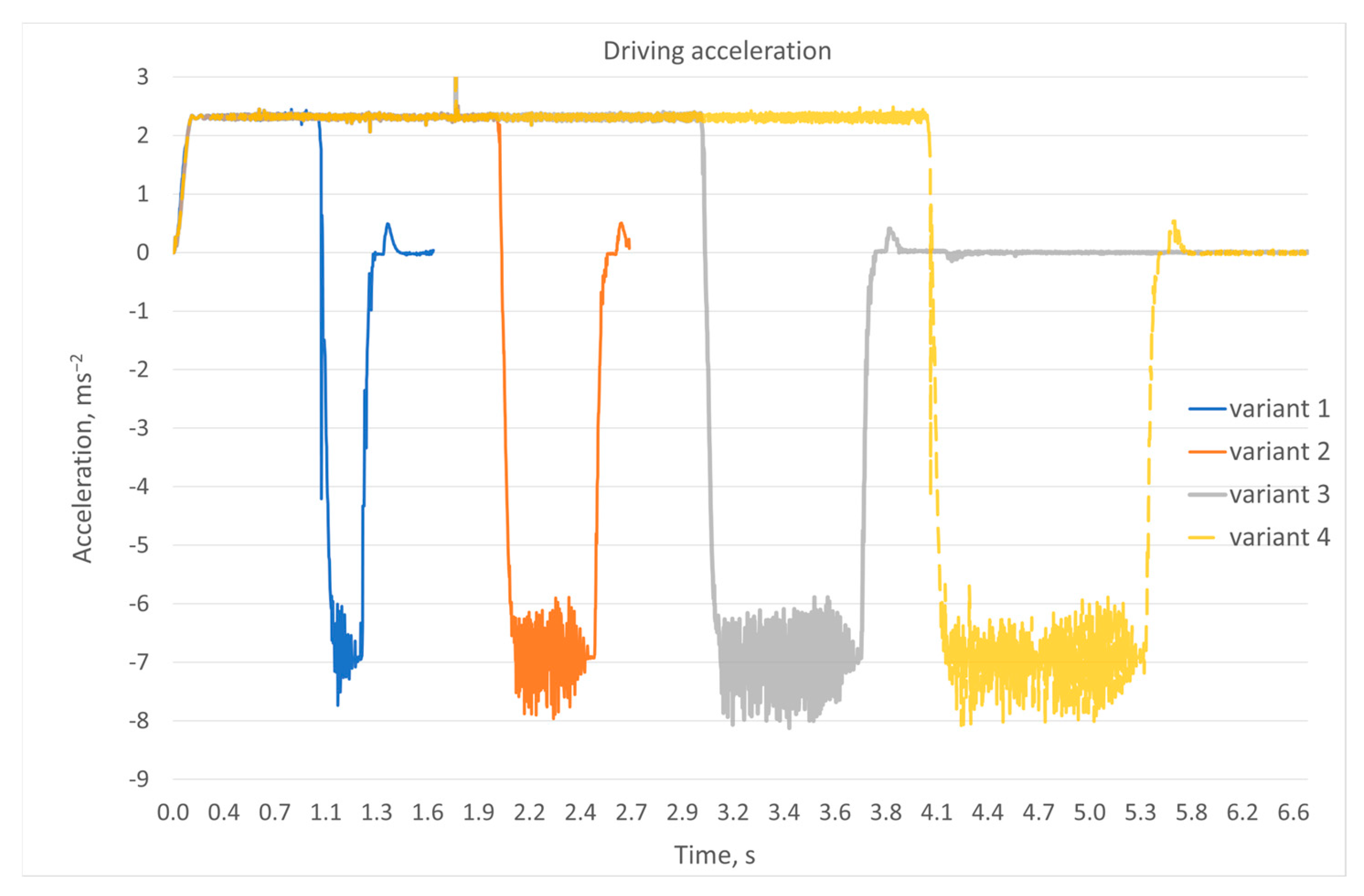
The maximum deceleration during emergency braking is another aspect regulated by law and having a significant impact on the safety of the driver and the crew. Polish law stipulates that this deceleration value cannot exceed an overload of 10 ms−1, which is not significantly higher than 1 G. The braking force of the multi-disc brakes was selected to obtain a maximum overload of approximately 0.8 G. The acceleration values recorded during the simulation for each variant are shown in Figure 6.
In Table 1, the minimum acceleration values, overloads, and braking time recorded during emergency braking in each of the analysed variants are presented.
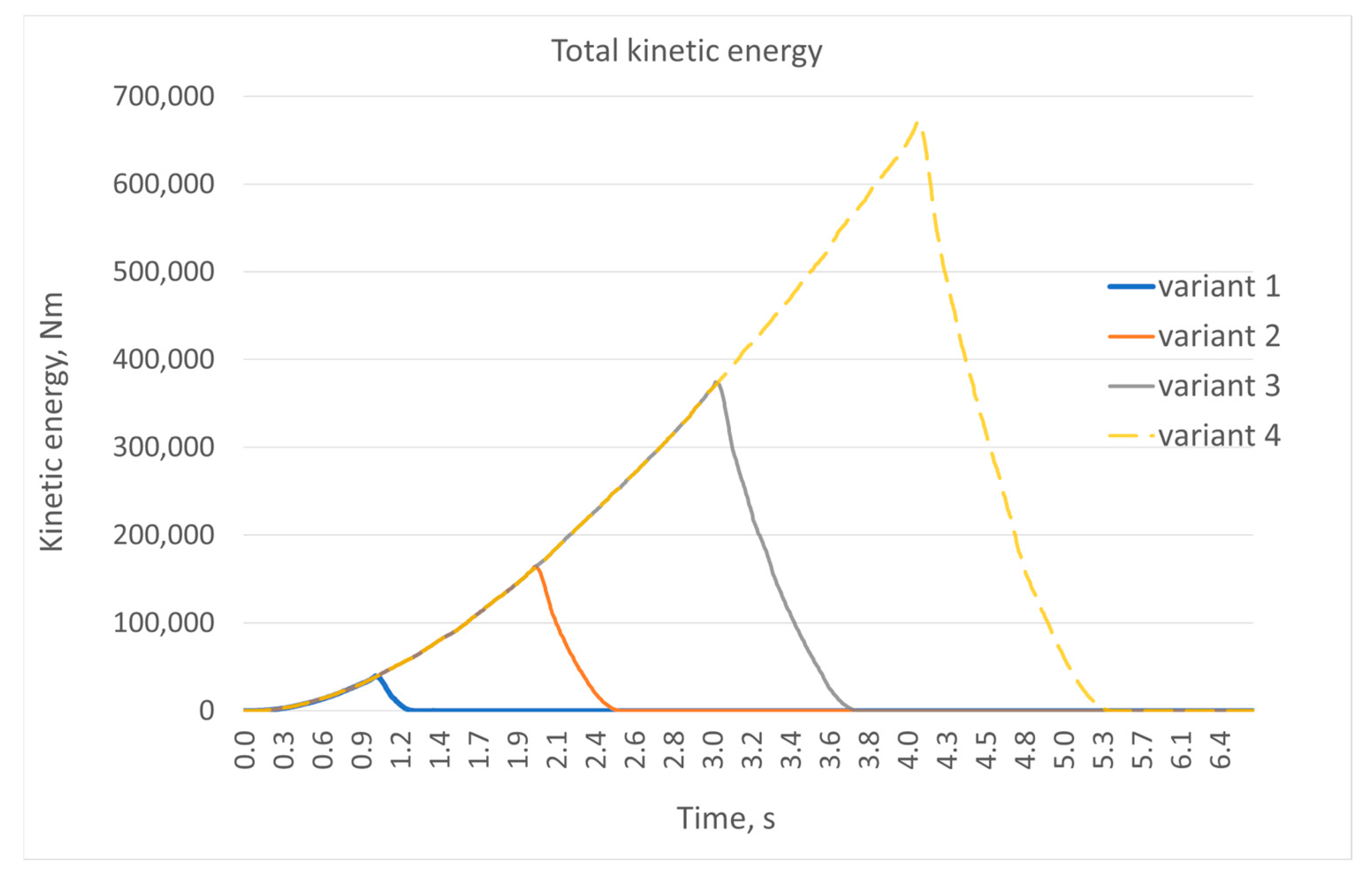
During the braking process, most of the kinetic energy of a speeding transport unit is dissipated as thermal energy generated by the actuators (friction) of the braking device. In emergency braking simulations, the total kinetic energy of the transportation set was determined at various speeds. For simplification purposes, it was assumed that all of this energy is converted into thermal energy, which is generated on the friction surfaces in the multi-disc brake. As is known, kinetic energy is directly related to the square of speed. This is a direct cause of the problem of exceeding the permissible surface temperature during emergency braking at speeds higher than permitted by law. This implies the need to develop a new solution to this problem. Figure 7 presents curves of the total kinetic energy of the transport set in relation to the emergency braking simulation variants.
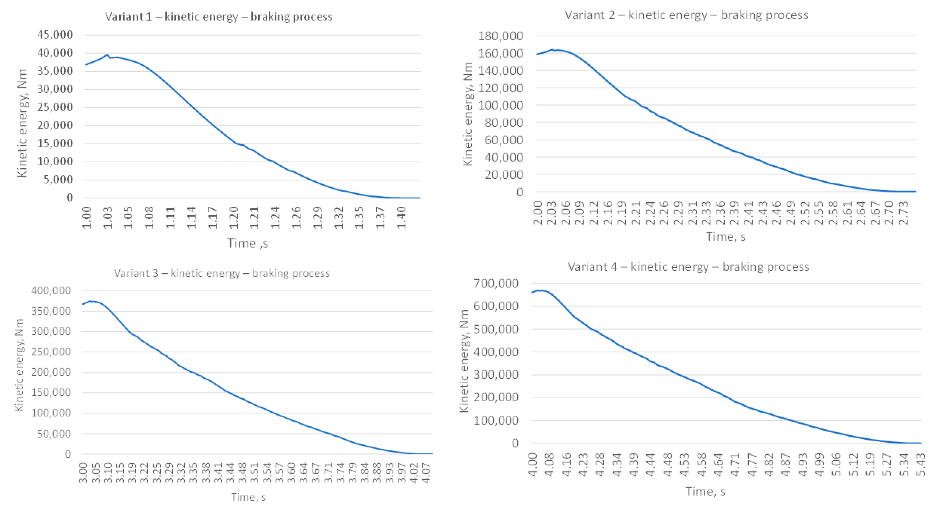
Purpose of determining the kinetic energy curve of the transport set was to calculate input data for thermal analyses using the FEM. This article assumes that the braking process begins when the maximum driving speed is reached and the braking forces are activated (pressure of the brake pads in a multi-disc brake). The braking process ends when the transport set speed reaches 0. Figure 8 presents kinetic energy curve segments recorded during the emergency braking process for all four simulation variants.

3.2. Results of MES Simulation

Based on the physical relationships between the kinetic energy and the power of the system, the following equation has been assumed.
P = d E k d t
The system’s energy is dissipated and released as heat flux between the brake discs and the surfaces they are pressed against. The surface area of the ten brake discs was 0.57 m2. Table 2 presents the maximum kinetic energy of the complete transportation set, the system’s power, and the heat flux released during the FEM simulation.
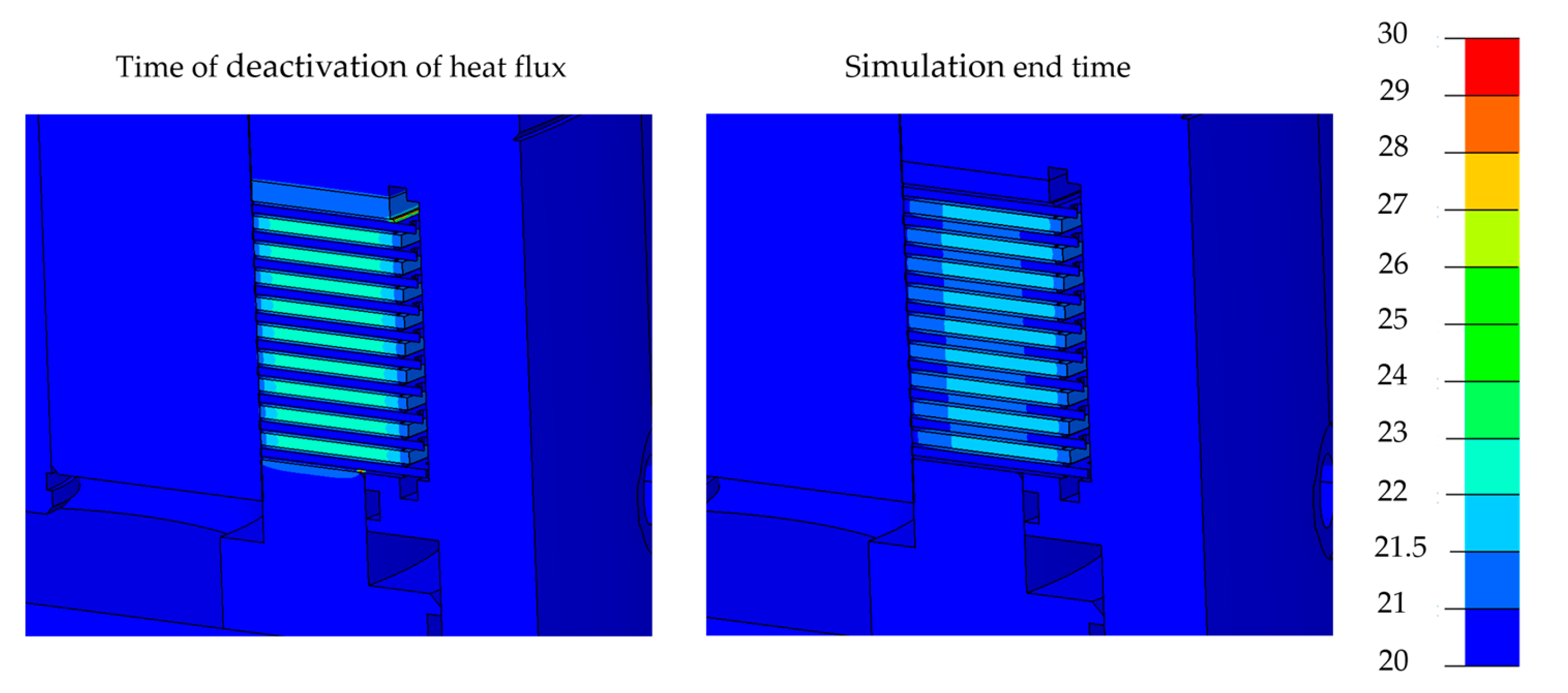
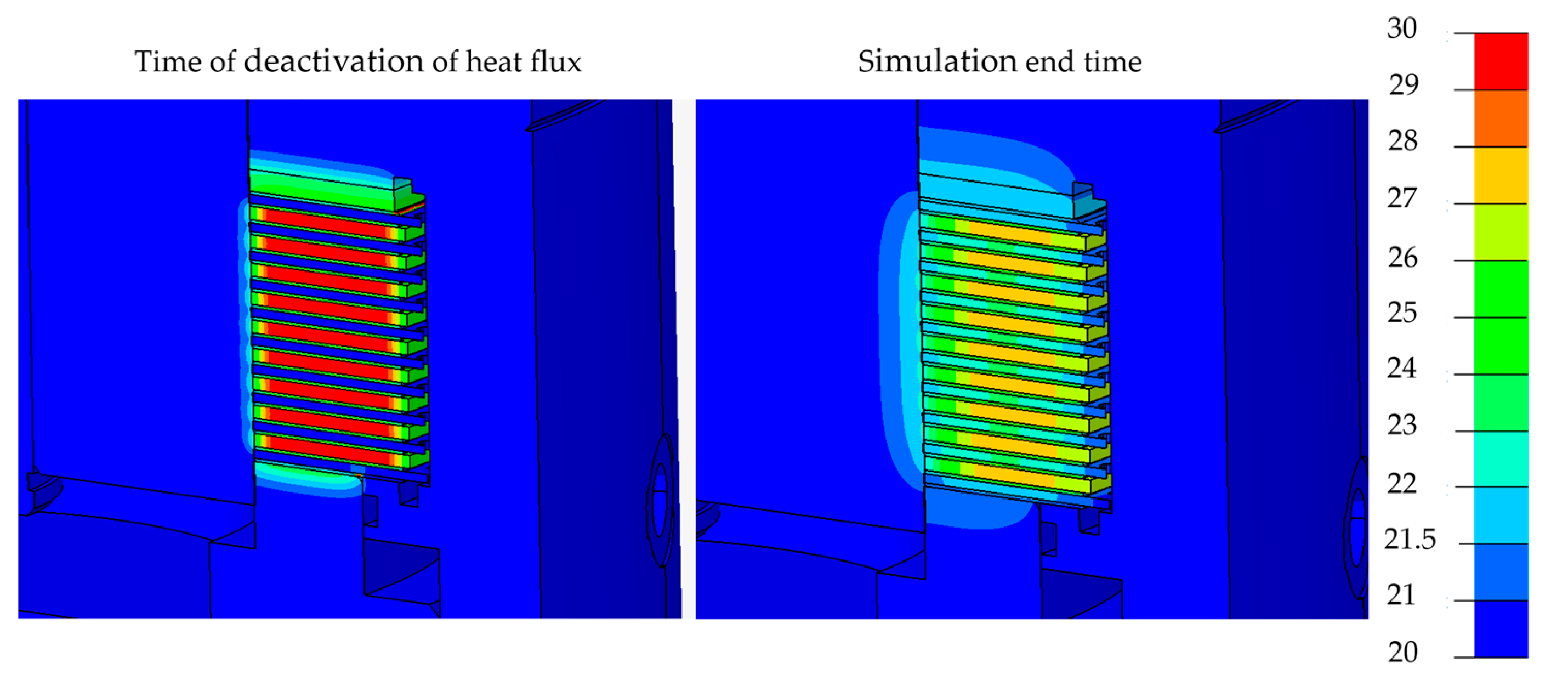
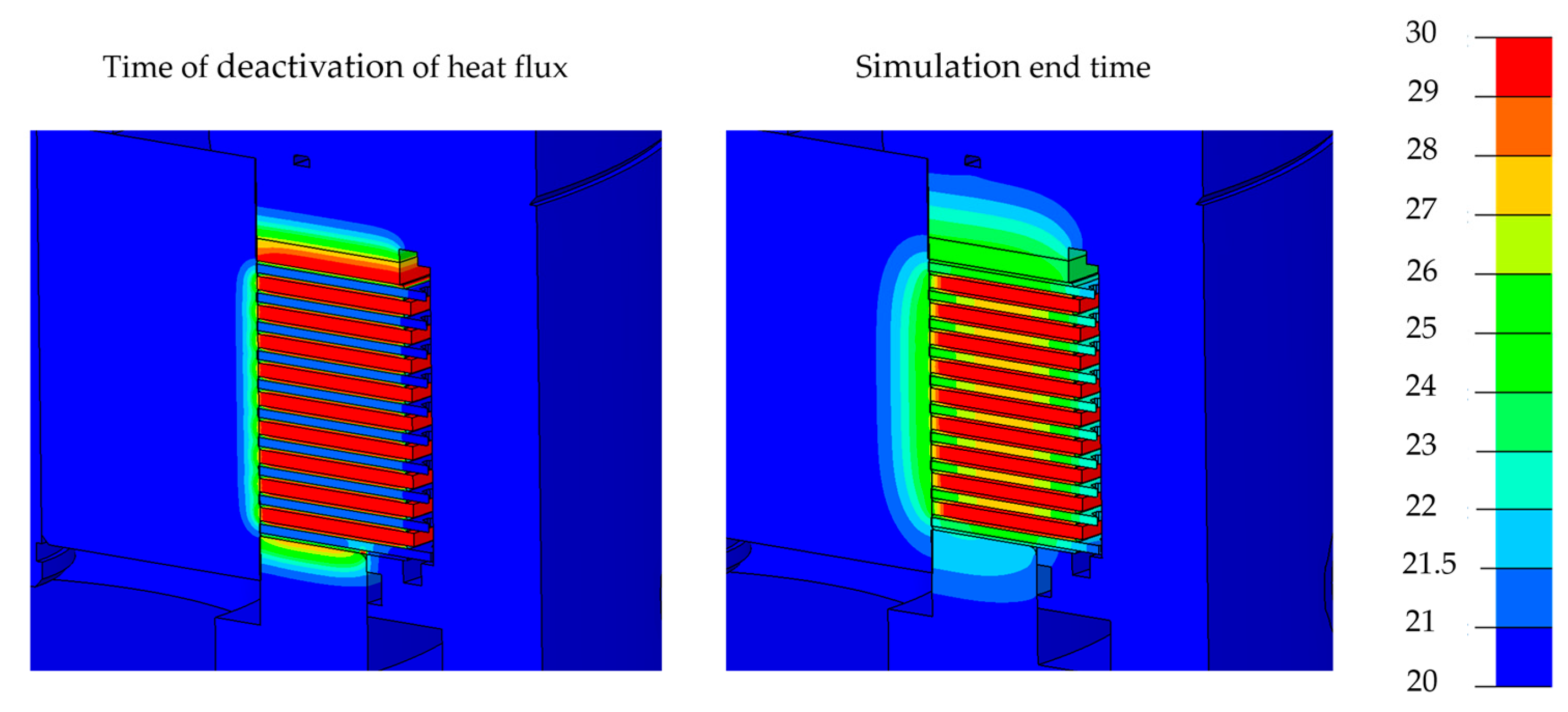
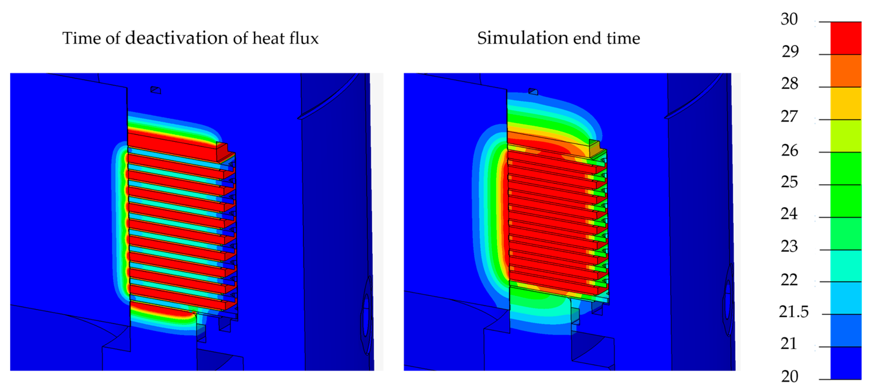
Figure 9, Figure 10, Figure 11 and Figure 12 present the results of numerical calculations in the form of thermal maps of the multi-disc brake area: at the moment of termination of the heat flux deactivation and at the end of the simulation process, i.e., at 5 s.
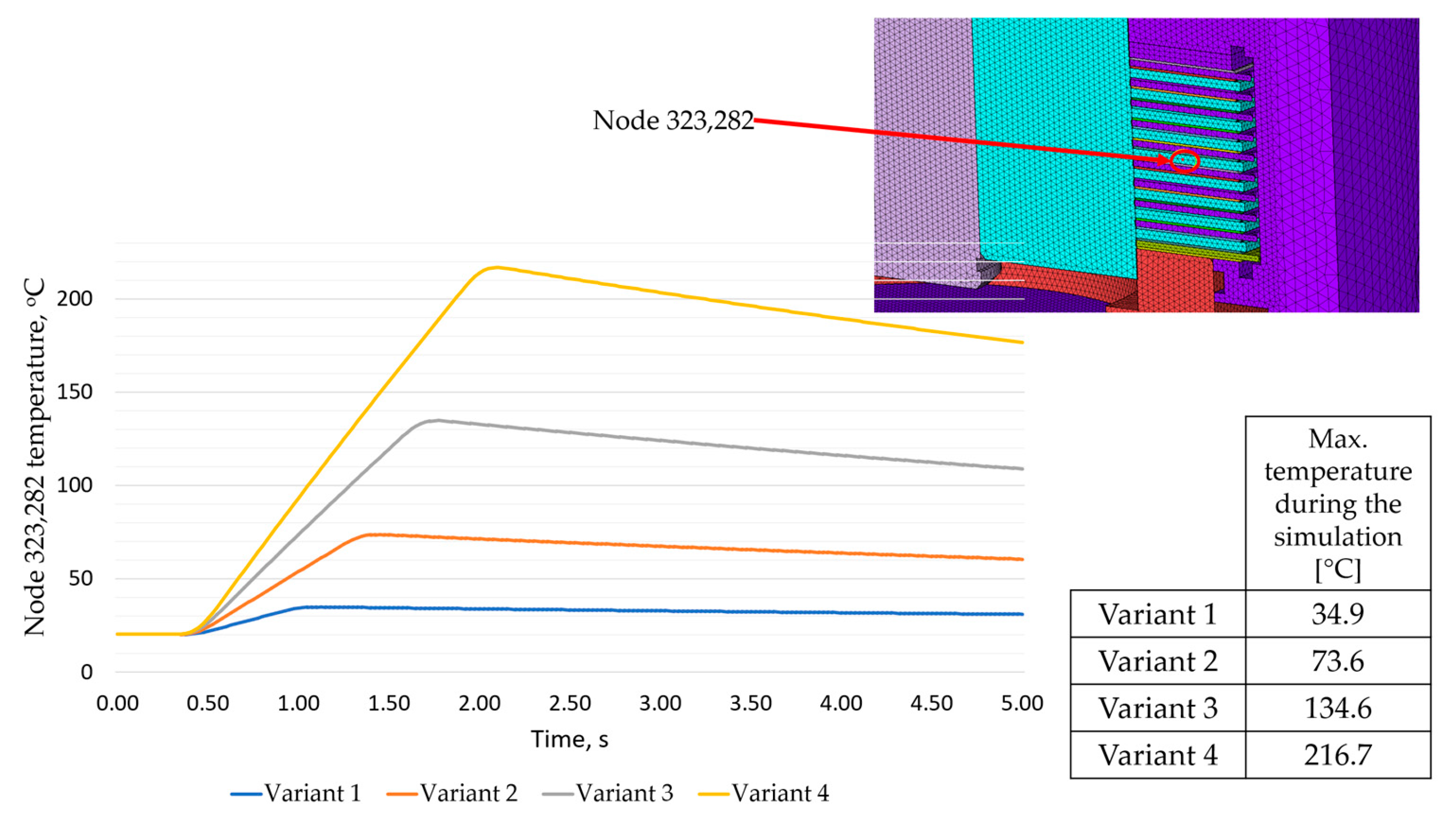
For comparison, Figure 13 shows the temperature changes in node no. 323,282 in each variant, along with its location. The figure also shows the maximum temperature.

4. Discussion

The presented solution and concept of the new braking device are a preliminary proposal for adapting emergency braking devices to higher-speed operations. The simulation results presented in this article are one of the first steps aimed at developing and verifying the correct operation of the analysed device. Therefore, it is important to be aware that the assumed model simplifications and boundary conditions are rough results that allow for an assessment of the feasibility of further, more detailed work, for example, regarding topographic optimisation of the brake assembly enclosure. One aspect that should be considered is the possibility of the friction wheel becoming stopped during emergency braking. This can happen when rails are dirty or damp, significantly reducing the coefficient of friction between the friction wheel and the suspended rail. When the friction wheels slip, the location of thermal energy release changes, resulting in contact between the friction wheel and the rail web. Preventing this type of friction wheel blocking can be realised in several ways. One method is to use steel friction wheels with a knurled contact surface with the rail, which will prevent wheel slippage. Another approach is to develop an intelligent braking monitoring system whose operation would be analogous to ABS systems in the automotive industry.
Another aspect that should be analysed in further work concerns the detailed numerical thermal analyses. These analyses will allow for the impact of local oil heating in the area of the brake pads to be taken into account, as well as the ability to analyse changes in the physical properties of multi-disc brake components (e.g., related to thermal deformation, thermal stress, etc.).
When developing a new emergency braking device, it is essential to consider all the problems and issues discussed in the introduction. Therefore, it is necessary to consider the possibility of modifying the design and changing the parameters of components, such as the springs pressing the friction wheels against the rail. If necessary, by modifying the spring stiffness and lever arm length, it is possible to develop a series of devices characterised by appropriate braking force. In such a case, the number and variant of the device should be selected for the specific transportation set. This is to ensure that the maximum permissible overload acting on people in the monorail is not exceeded. It is also worth considering the possibility of implementing a sequential braking algorithm in the device, ensuring both adequate braking efficiency and the safety of both the crew and the route.
Another issue concerns the limiting speeds adopted for the purposes of this study, at which emergency braking occurs. It should be emphasised that the maximum speed of suspended monorails during crew transport in Poland is 2 m/s. Literature analyses and the authors’ experience indicate the need to change the regulations permitting crews to travel at speeds greater than 2 m/s. Currently, it is impossible to determine what maximum speed can be considered permissible. This, of course, requires appropriate modifications and adjustments to the suspended monorail route and its routes, along with appropriate regulations.
The capabilities and limitations of numerical models should also be taken into account. In the models presented, parameter values were adopted based on experience and previous research and developed by the authors of the models. However, changing the type of friction wheel lining changes the wheel–rail friction coefficient. Similarly, a change in the diameter of the friction wheel resulting from wear affects the dynamic phenomena occurring in the device. Another area of nuance is the selection and characteristics of the springs pressing against the brake pads. The type of oil used in the brake can also affect the efficiency of the braking and heat dissipation processes. Such nuances may cause some discrepancies between the simulation results and the actual object. Therefore, an important phase of the research will be the validation of the computational models when a prototype of the device is created.

5. Conclusions

The concept of a new emergency braking device can be safely used when suspended monorails operate at speeds higher than currently permitted. The presented analyses are the first step of the research work and require extensive detailing and appropriate approvals for use in underground mines. Nevertheless, the development of such a device solves a number of problems related to emergency braking, which may prompt discussions with legislative bodies to amend the legal regulations specifying the permissible speeds of suspended monorail transport units. One of the main advantages of implementing this type of solution is ensuring that the transformation of kinetic energy into thermal energy occurs in an isolated space, without causing significant temperature changes on surfaces in contact with a potentially explosive atmosphere. Taking into account the remaining limitations mentioned in the introduction and discussion sections, such a device may contribute to the development of suspended railways towards speedy underground railway units, thus increasing the efficiency and profitability of mining processes.
According to the authors, it is very important to raise awareness of existing risks and then find solutions to minimise their occurrence. The expansion of the presented concept, together with the development of an appropriate control system for the braking device, provides an opportunity for the development of underground transport systems. At the same time, this concept provides an opportunity to increase safety and work efficiency, as well as an opportunity for the development of companies manufacturing suspended railway equipment. The topics addressed are relevant on the international stage, which allows for their global application without territorial restrictions.

6. Patents

As part of the research work, i.e., the design and construction process along with virtual prototyping, a Polish patent No. 245925 was obtained, “Emergency braking device with multi-disc brakes”.

Author Contributions

Conceptualisation, J.T. and K.S.; methodology, J.T. and K.S.; software, J.T. and K.S.; data curation, J.T. and Ł.O.; writing—original draft preparation, K.S. and J.T.; writing—review and editing, K.S.; visualisation, J.T. and D.M.; supervision, J.T. and D.M. All authors have read and agreed to the published version of the manuscript.

Funding

This research received no external funding.

Institutional Review Board Statement

Not applicable.

Informed Consent Statement

Not applicable.

Data Availability Statement

The original contributions presented in this study are included in the article. Further inquiries can be directed to the corresponding author.

Acknowledgments

Calculations were carried out at the Academic Computer Centre in Gdańsk, Poland.

Conflicts of Interest

The authors declare no conflict of interest.

References

  1. Świder, J.; Szewerda, K.; Tokarczyk, J.; Plewa, F.; Grodzicka, A.; Kędzia, K. An Overview of Possibilities of Increasing the Permissible Speed of Underground Suspended Monorails for Transporting People in the Conditions of Polish Underground Mining. Energies 2023, 16, 3703. [Google Scholar] [CrossRef]
  2. Szewerda, K.; Tokarczyk, J.; Wieczorek, A. Impact of Increased Travel Speed of a Transportation Set on the Dynamic Parameters of a Mine Suspended Monorail. Energies 2021, 14, 1528. [Google Scholar] [CrossRef]
  3. Gutarevych, V. Dynamic model of movement of mine suspended monorail. Transp. Probl. 2014, 9, 13–18. [Google Scholar]
  4. Becker, F.; Zell, M. The state of the art in positively guided rail transport systems for underground mining. Min. Rep. 2014, 150, 34–46. [Google Scholar] [CrossRef]
  5. Song, Z.A.; Jiang, F. Hydraulic system elaboration and simulation for single-drive light-load monorail locomotive in fully mechanized coal mining applications. IOP Conf. Ser. Mater. Sci. Eng. 2019, 474, 012006. [Google Scholar] [CrossRef]
  6. Herbuś, K.; Szewerda, K.; Świder, J. Virtual prototyping of the suspended monorail in the aspect of increasing the permissible travel speed in hard coal mines. Eksploat. Niezawodn. 2020, 22, 610–619. [Google Scholar] [CrossRef]
  7. Regulation of the Minister of Energy of 23 November 2016 on Detailed Requirements for the Operation of Underground Mining Plants. J. Laws Repub. Pol. 2017, 1118. Available online: https://www.dziennikustaw.gov.pl/du/2017/1118 (accessed on 19 December 2025).
  8. Yilmaz, A.I.; Büyükyildiz, G.; Ekici, A.; Çalik, M.; Önder, Ö.; Aksoy, C.O. Staff transportation two way on the belt conveyor. Acta Montan. Slovaca 2013, 18, 141–150. [Google Scholar]
  9. Pieczora, E.; Suffner, H. Rozwój napędów dołowych kolejek podwieszonych [Development of underground drives for suspended monorails]. Min. Mach. 2017, 3, 44–57. [Google Scholar]
  10. Szewerda, K.; Tokarczyk, J.; Świder, J.; Grodzicka, A. Impact of suspension and route stabilization on dynamic parameters of self-driven mine suspended monorails. Eksploat. Niezawodn. 2022, 24, 617–628. [Google Scholar] [CrossRef]
  11. Stankiewicz, K. Mechatronic systems developed at the KOMAG. Min. Mach. 2020, 162, 58–68. [Google Scholar] [CrossRef]
  12. Jagoda, J.; Hetmańczyk, M.; Stankiewicz, K. Dispersed, self-organizing sensory networks supporting the technological processes. Min. Mach. 2021, 2, 13–23. [Google Scholar] [CrossRef]
  13. Kuric, I.; Cisar, M.; Tlach, V.; Zajačko, I.; Gál, T.; Więcek, D. Technical Diagnostics at the Department of Automation and Production Systems. In Intelligent Systems in Production Engineering and Maintenance; Advances in Intelligent Systems and Computing; Springer: Berlin/Heidelberg, Germany, 2019; Volume 835, pp. 474–484. [Google Scholar] [CrossRef]
  14. Lutyński, A. KOMAG activities in the domestic and international research areas. Min. Mach. 2021, 4, 47–60. [Google Scholar] [CrossRef]
  15. PN-G 46860:2011; Mine Railway Systems—Braking Trolleys and Emergency Braking Devices—Requirements. Polish Committee for Standardization: Warsaw, Poland, 2011.
  16. Prochowski, L.; Żuchowski, A. Analysis of the influence of passenger position in a car on a risk of injuries during a car accident. Eksploat. Niezawodn. 2014, 16, 360–366. [Google Scholar]
  17. Kowalski, P.; Zajęć, J. Research on simultaneous impact of hand-arm and whole-body vibration. JOSE Int. J. Occup. Saf. Ergon. 2012, 18, 59–66. [Google Scholar] [CrossRef]
  18. Pytlik, A. Tests of steel arch and rock bolt support resistance to static and dynamic loading induced by suspended monorail transportation. Stud. Geotech. Mech. 2019, 41, 81–92. [Google Scholar] [CrossRef]
  19. Pytlik, A.; Rotkegel, M.; Szot, Ł. Investigation of the effect of suspended monorail speed on forces in selected route elements. Przegląd Górniczy 2016, 11, 30–37. [Google Scholar]
  20. Drozd, K.; Nieoczym, A. Dynamic Load of Suspension Chains Generated during the Movement of the Self-Powered Diesel Transportation System on a Suspended Monorail Track in the Mining Excavation; Monograph; Lublin University of Technology: Lublin, Poland, 2020; ISBN 978-83-7947-426-4. [Google Scholar]
  21. Dumitriu, M.; Gheți, M.A.; Cruceanu, I.C. Experimental Analysis of the Vertical Vibration of the Railway Bogie During Braking. Procedia Manuf. 2020, 46, 49–54. [Google Scholar] [CrossRef]
  22. Wojtyra, M.; Frączek, J. Metoda Układów Wieloczłonowych w Dynamice Mechanizmów; Oficyna Wydawnicza Politechniki Warszawskiej: Warsaw, Poland, 2007; ISBN 978-83-7207-703-5. [Google Scholar]
  23. Pástor, M.; Živčák, J.; Puškár, M.; Lengvarský, P.; Klačková, I. Application of Advanced Measuring Methods for Identification of Stresses and Deformations of Automotive Structures. Appl. Sci. 2020, 10, 7510. [Google Scholar] [CrossRef]
  24. Danelson, K.A.; Golman, A.; Kemper, A.; Gayzik, F.; Gabler, H.C.; Duma, S.M.; Stitzel, J.D. Finite element comparison of human and Hybrid III responses in a frontal impact. Accid. Anal. Prev. 2015, 85, 125–156. [Google Scholar] [CrossRef]
  25. Verstraete, M.L.; Roccia, B.A.; Mook, D.T.; Preidikman, S. A co-simulation methodology to simulate the nonlinear aeroelastic behavior of a folding-wing concept in different flight configurations. Nonlinear Dyn. 2019, 98, 907–927. [Google Scholar] [CrossRef]
  26. Waddad, Y.; Magnier, V.; Dufrénoy, P.; De Saxcé, G. Multiscale thermomechanical modelling of frictional contact problems considering wear—Application to a pin-on-disc system. Wear 2019, 426–427, 1399–1409. [Google Scholar] [CrossRef]
  27. Jiang, Y.; Zhong, W.; Wu, P.; Zeng, J.; Zhang, Y.; Wang, S. Prediction of wheel wear of different types of articulated monorail based on co-simulation of MATLAB and UM software. Adv. Mech. Eng. 2019, 11, 1687814019856841. [Google Scholar] [CrossRef]
  28. Horyl, P.; Šňupárek, R.; Maršálek, P.; Poruba, Z.; Pacześniowski, K. Parametric Studies of Total Load-Bearing Capacity of Steel Arch Supports. Acta Montan. Slovaca 2019, 24, 213–222. [Google Scholar]
  29. INESI European Project: Increase Efficiency and Safety Improvement in Underground Mining Transportation Routes. RFCS, 2017–2020, Contract No. 754169. Available online: https://inesi.komag.eu (accessed on 19 December 2025).
  30. Małkowski, P.; Ostrowski, Ł.; Bednarek, Ł. The Effect of Selected Factors on Floor Upheaval in Roadways—In Situ Testing. Energies 2020, 13, 5686. [Google Scholar] [CrossRef]
  31. Wu, G.; Chen, W.; Jia, S.; Tan, X.; Zheng, P.; Tian, H.; Rong, C. Deformation characteristics of a roadway in steeply inclined formations and its improved support. Int. J. Rock Mech. Min. Sci. 2020, 130, 104324. [Google Scholar] [CrossRef]
  32. Spiryagin, M.; Persson, I.; Wu, Q.; Bosomworth, C.; Wolfs, P.; Cole, C. A co-simulation approach for heavy haul long distance locomotive-track simulation studies. Veh. Syst. Dyn. 2019, 57, 1363–1380. [Google Scholar] [CrossRef]
  33. Wicher, J.; Więckowski, D. Influence of vibrations of the child seat on the comfort of child’s ride in a car. Eksploat. Niezawodn. 2010, 4, 102–110. [Google Scholar]
  34. Żuchowski, A. Analysis of the influence of the impact speed on the risk of injury of the driver and front passenger of a passenger car. Eksploat. Niezawodn. 2016, 18, 436–444. [Google Scholar] [CrossRef]
  35. Kałuża, G. Temperature measurements in the process of testing explosion-proof devices. Masz. Elektr. Zesz. Probl. 2017, 1, 85–89. [Google Scholar]
  36. Yevtushenko, A.A.; Grzes, P. Mutual influence of the sliding velocity and temperature in frictional heating of the thermally nonlinear disc brake. Int. J. Therm. Sci. 2016, 102, 254–262. [Google Scholar] [CrossRef]
  37. Lian, Q.; Deng, G.; Tieu, A.K.; Li, H.; Liu, Z.; Wang, X.; Zhu, H. Thermo-mechanical coupled finite element analysis of rolling contact fatigue and wear properties of a rail steel under different slip ratios. Tribol. Int. 2020, 141, 105943. [Google Scholar] [CrossRef]
  38. PN-EN ISO 80079-36:2016-07; Explosive Atmospheres—Part 36: Non-Electrical Equipment for Explosive Atmospheres—Basic Method and Requirements. Polish Committee for Standardization: Warsaw, Poland, 2016.
  39. Górny, M. Ignition risk assessment of nonelectrical part of drive system. Napędy Sterow. 2017, 19, 82–88. [Google Scholar]
  40. Krause, E.; Smoliński, A. Analysis and assessment of methane hazard-producing parameters in longwall environments. J. Sustain. Min. 2013, 12, 13–19. [Google Scholar] [CrossRef]
  41. Cioca, I.L.; Moraru, R.I. Explosion and/or fire risk assessment methodology: A common approach, structured for underground coal mine environments. AMS 2012, 57, 53–56. [Google Scholar] [CrossRef]
Figure 1. Emergency braking device for a high-speed suspended railway with a multi-disc brake: (a) Front view; (b) side view; (c) isometric view.
Applsci 16 01338 g001
Figure 2. Longitudinal section through the brake lever assembly.
Applsci 16 01338 g002
Figure 3. Computational model of MBS class.
Applsci 16 01338 g003
Figure 4. Computational model of multi-disc brake developed for thermal calculations: (a) Side view; (b) front view; (c) isometric view; and (d) close-up view of brake discs.
Applsci 16 01338 g004
Figure 5. Time process of the speed of a transportation set.
Applsci 16 01338 g005
Figure 6. Time process of acceleration recorded during the simulation of emergency braking.
Applsci 16 01338 g006
Figure 7. Time process of kinetic energy of the transportation set.
Applsci 16 01338 g007
Figure 8. Time process of transportation set kinetic energy during the emergency braking.
Applsci 16 01338 g008
Figure 9. Temperature distribution (°C) in the area of the multi-disc brake at the moment of termination of the heat flux deactivation and at the end of the simulation: variant 1.
Applsci 16 01338 g009
Figure 10. Temperature distribution (°C) in the area of the multi-disc brake at the moment of termination of the heat flux deactivation and at the end of the simulation: variant 2.
Applsci 16 01338 g010
Figure 11. Temperature distribution (°C) in the area of the multi-disc brake at the moment of termination of the heat flux deactivation and at the end of the simulation: variant 3.
Applsci 16 01338 g011
Figure 12. Temperature distribution (°C) in the area of the multi-disc brake at the moment of termination of the heat flux deactivation and at the end of the simulation: variant 4.
Applsci 16 01338 g012
Figure 13. Curves of temperature changes inside the brake disc in variants 1–4 (node no. 323,282 and its location).
Applsci 16 01338 g013
Table 1. Acceleration, overload, and braking time for each variant.
Variant No.Minimum Acceleration, ms−2OverloadBraking Time (Deceleration Action), s Time from the Moment of Starting the Braking Force Increase Until Stopping V = 0
1−7.740.79 g0.425 s
2−7.960.81 g0.76 s
3−8.120.83 g1.09 s
4−8.160.83 g1.43 s
Table 2. The maximum values of the kinetic energy of the system and the corresponding power and heat flux.
Variant No.Maximum Kinetic Energy of the Set, NmPower of the System, WHeat Flux, W/m2
139,62493,232.9163,566.0
2164,076215,889.5378,753.5
3374,325343,417.43602,486.72
4670,420468,825.17822,500.3
Disclaimer/Publisher’s Note: The statements, opinions and data contained in all publications are solely those of the individual author(s) and contributor(s) and not of MDPI and/or the editor(s). MDPI and/or the editor(s) disclaim responsibility for any injury to people or property resulting from any ideas, methods, instructions or products referred to in the content.