Article

Dynamic Characteristics of Rolling Elements in Cageless Bearings Based on a Nonlinear Dynamic Model

1
School of Mechanical Engineering, Jiangsu University of Science and Technology, Zhenjiang 212100, China
2
Key Laboratory of Advanced Manufacturing and Intelligent Technology, Ministry of Education, Harbin University of Science and Technology, Harbin 150080, China
*
Author to whom correspondence should be addressed.
Appl. Sci. 2026, 16(18), 9284; https://doi.org/10.3390/app16189284 (registering DOI)
Submission received: 11 August 2026 / Revised: 6 September 2026 / Accepted: 7 September 2026 / Published: 19 September 2026

Abstract

The main reason cageless bearings fail as protective bearings for magnetic levitation bearings is the uncontrolled motion of isolated rolling elements without a cage. This leads to sliding, friction, and collisions between the rolling element and the raceway, or among the rolling elements themselves. In this work, the universal nonlinear dynamic model of cageless bearings is established. The kinematic behavior of the rolling element in the cageless bearing is analyzed, and the sliding and discontinuous contact collision phenomena of the rolling element are explained from a kinematic perspective. Subsequently, the influence of different working conditions on the rolling-element contact behavior is demonstrated. In the model incorporating the randomness of rolling elements in cageless bearings, the numerical solution method is optimized. Experimental results confirm that the model is correct. The primary contact between adjacent rolling elements occurs in the transition zone between the loaded and unloaded zones. The higher the rotational speed, the less likely the rolling element is to collide and make contact. The larger the axial load, the more likely the rolling element is to rub continuously. The influence of radial load on the slip rate of the rolling elements is relatively small. These results provide a suitable operating range for cageless bearings.

1. Introduction

A large number of bearing failures in turbines of aircraft-propelled gas turbine units and other applications are caused by high-frequency sliding contact between the cage and the rolling elements. Researchers believe that rolling bearings without cages can effectively eliminate faults. Therefore, a fully loaded bearing without a cage has been proposed [1]. Experimental studies on wear and rolling moment associated with full complement ball bearings appeared in the 1960s. In the early 1980s, with the development of magnetic bearing rotor systems, the process of rotor drop has gradually been used as backup bearings for rocket engine rotor systems due to the fact that fully loaded ball bearings retain the characteristics of ball bearings suitable for high-speed rotation while improving radial stiffness and load-bearing capacity [2,3]. At the same time, since there is no cage to limit the range of motion of the rolling elements, the dropping rotor drives the cageless bearing to rotate. The smooth operation of the rotor is directly influenced by the kinematic behavior of the rolling elements. Therefore, investigating the kinematic behavior of the rolling elements is of great significance for maintaining the dynamic behavior of the rotor system.
Research on the motion of bearing rolling elements mainly focuses on both experimental and theoretical aspects. In references [4,5,6,7], high-speed photography was used to observe the kinematic behavior by tracking the contact-point trajectories of rolling elements, and it was found that cageless bearings exhibit smaller rotational deflection and more stable operation during the rotor drop process. Townsend et al. [8] found through comparative torque experiments that the friction torque caused by sliding between rolling elements is the main factor affecting the motion stability of rolling elements. However, the applicability of empirical relationships obtained through experiments is limited to bearings used under a certain model and similar test conditions. For cageless bearings with different dimensional parameters under different operating conditions, bearing rolling element motion testing is usually not possible due to time and financial constraints. Therefore, it is essential to develop a general model for the motion characteristics of rolling elements.
In bearing dynamics modeling, within the quasi-static framework, Gupta [9] considered the six-degree-of-freedom motion of the rolling element and established a transient motion model. For the rolling element, the sliding rate under specific operating conditions served as a parameter characterizing its motion. Jain et al. [10] developed a rolling element–raceway friction model combined with lubrication theory. Accounting for the effect of centrifugal force on high- speed rolling elements, the model also quantifies the impact of the applied load on their sliding behavior. Houpert [11,12] and Wang et al. [13] investigated the cage–rolling element interaction, derived the governing dynamic equations that incorporate pocket geometry and nonlinear contact effects, and quantified the cage’ s influence on rolling- element sliding. Li et al. [14] investigated a bearing dynamics model for rolling- element sliding during entry into and exit from the bearing area. Based on the sliding characteristics, the relationship between slip and load and speed was obtained via the prediction-correction variable-step integration method. The authors analyzed the constraint capability of cage pocket geometric deformation on the centrifugal motion of ceramic balls and thereby determined the bearing trajectory. Yu [15] introduced continuous contact forces, used a modified friction model for the ball–raceway tangential interaction, proposed a planar multibody dynamic model that considered contact characteristics of ball bearings, and obtained the vibration characteristics of rolling- element impacts induced by the clearance in the raceway structure. Deng et al. [16] examined the dependence of cage- rolling element collisions on inner- ring groove radius and rolling- element population and explored the sliding characteristics of rolling elements. Based on equilibrium forces and moments, Yu et al. [17] optimized the multibody dynamics modeling and solution methods for ball bearings by integrating contact, lubrication, and other relevant factors. They developed a fully coupled transient solution method, which enhances the fidelity of the bearing model.
In the above studies, the kinematic behavior of the rolling element, although constrained by the cage, is similar to that in cageless bearings. The conditional assumptions are ideal; in practical applications, the motion of rolling elements in a cageless bearing is inherently stochastic. However, research on cageless bearings primarily focuses on the effect of rotor drop on rotor operational stability. Cole et al. [18] explained the dynamic behavior of a 2-degree-of-freedom bearing and established a rolling and sliding model for the inner race of the rotor and cageless bearing. This research predicted the time at which the rolling element movement caused the rotor to operate stably under impact load. Neisi et al. [19] derived the relationship between friction resistance and velocity features in the rolling element–raceway contact by analyzing the model of frictional resistance generated by relative sliding motion, assuming a uniform distribution of non-contact rolling elements in the cageless bearing. Based on Neisi’s research, Zhilnikov et al. [20] considered the problem of rolling elements contacting each other during the start-up stage of cageless bearings and investigated a differential equation of motion for rolling elements with 2 degrees of freedom. They revealed that the rolling elements first separate and then experience discontinuous contact during operation. Accumulation of the rolling element caused by this random contact results in rotor instability. Helfert [21] observed the motion pattern of the rotor drop bearing using high-speed photography, inferred the variation law of the revolution speed of the rolling element in the cageless bearing, and established a model of the rolling element speed and contact force to verify the sliding behavior of the rolling element.
Based on the research above, the motion behavior of rolling elements is critical to rotor system dynamics. However, despite these contributions, several limitations remain in existing studies on cageless bearing dynamics. In terms of modeling dimensionality, early models mostly adopted 2-DOF simplifications, considering only the orbital motion of rolling elements while retaining the assumption of circumferentially uniform spacing inherited from caged bearings, thus failing to capture spatial attitude variations or non-uniform contact characteristics. Regarding contact mechanisms, existing studies primarily focus on impact behavior, with limited systematic consideration of continuous torsional friction that may occur after collision, which restricts the model’s ability to capture actual motion behavior. In terms of numerical methods, conventional algorithms face convergence difficulties at contact force discontinuities, making it challenging to meet the stability requirements imposed by strong nonlinearities and abrupt characteristics. Regarding randomness characterization, existing studies lack a reasonable physical explanation for the randomness in rolling element motion observed in experiments, and its origin remains unclear. In terms of experimental validation, existing studies are predominantly numerical simulations without systematic experimental validation, leaving the reliability of model predictions to be further verified. These limitations constrain the predictive capability and engineering applicability of current cageless bearing dynamic models.
To address the above limitations, the present work introduces innovations in the following aspects:
(1) A 6-DOF dynamic model for rolling elements is developed, incorporating both instantaneous impact collisions and continuous torsional friction between adjacent rolling elements. This model overcomes the limitations of traditional 2-DOF models and more comprehensively captures the complex random rubbing-impact behavior in cageless bearings.
(2) A hybrid numerical solution strategy combining a Newton–Raphson quasi-static initial solution, Runge–Kutta transient handling, and Adams–GSTIFF variable-step main time-domain integration is developed, effectively resolving numerical convergence difficulties at contact discontinuities.
(3) The complex deterministic dynamic characteristics of rolling element motion are revealed through multiple-initial-condition deterministic simulations, showing that the observed randomness arises from the system’s inherent nonlinear dynamics rather than from external random excitations.
(4) High-speed photography experiments are conducted for the first time, tracking all 14 rolling elements and directly comparing theoretical predictions with experimental measurements, thereby systematically revealing how speed and load influence the dynamic behavior of the rolling elements.

2. Kinematic Model of Cageless Bearing

2.1. Theoretical Modeling and Coordinate System Conversion of Cageless Bearing

The kinematic model for cageless bearings computes contact forces at the rolling-element/raceway interface, accounting for deformation, load distribution, and interactions between adjacent elements. The analysis aims to predict rolling-element kinematic characteristics and bearing stability under skidding or impact. Simplified models, such as those used in vibration analysis, fail to produce satisfactory results because they omit cage constraints and the varying states of motion of each rolling element. In general, considering the actual bearing motion, the bearing is modeled with a fixed outer ring, an inner ring rotating at angular speed ωi, and subjected to either pure radial or combined axial-radial loads. The assumption is that the inner ring of the bearing possesses 3 DOF, whereas each rolling element has 6 DOF. The elastic deformation and contact force within the bearing follow Hertz elastic contact theory. For each bearing component, the mass center and geometric center coincide.
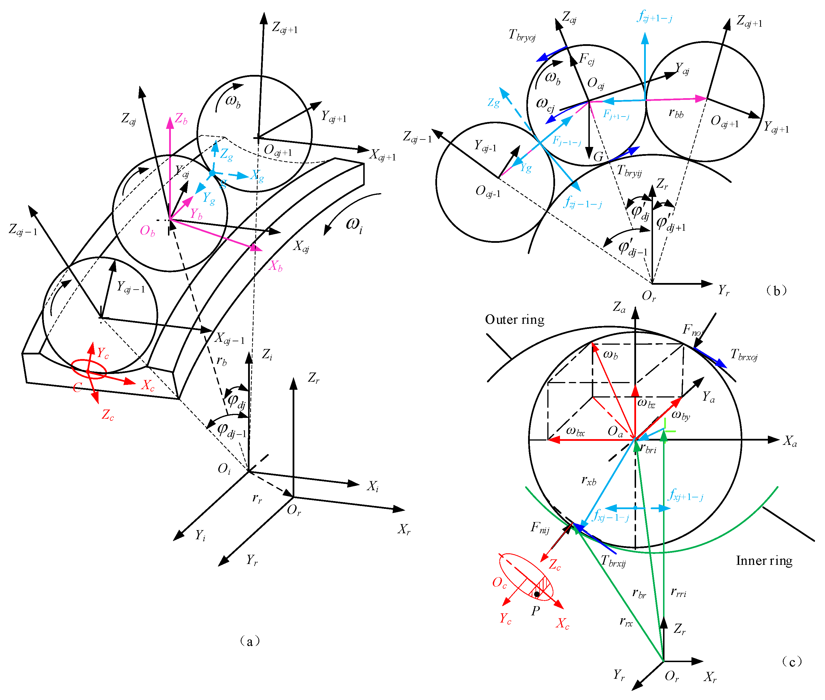
The spatial position and attitude of the rolling elements change during motion. To accurately describe the motion characteristics and interactions of each element inside the cageless bearing, a coordinate system is established for each rolling element (Figure 1a).
The following six coordinate systems, illustrated in Figure 1, are defined to characterize the forces and motions of each bearing component. The inertial coordinate system OiXiYiZi, whose position is fixed in space, has its origin at the bearing outer-race center, and the Xi axis coincides with the bearing’s symmetry axis. Two coordinate systems exist for each rolling element; the azimuthal coordinate system OaXaYaZa describes the element’s spatial position. The origin of this system is located at the center of mass of the rolling element. The Xa axis is aligned with the bearing axis, the Ya axis with the direction of circumferential motion, and the Za axis is defined by the right-hand rule. The azimuthal coordinate system rotates about the inertial Xi axis at the orbital angular velocity. The other coordinate system is the fixed body coordinate system ObXbYbZb, which represents the kinematic behavior of the rolling elements. Its center Ob of the azimuthal coordinate system, the Xb axis aligns with the rolling-element rotation axis. Initially, the body-fixed and azimuthal coordinate systems coincide.
The coordinate system OrXrYrZr is fixed to and follows the inner ring, which relates the inner ring’s position to its motion in space. The origin is located at the inner ring’s mass center, and Xr is always along the axis direction. The rolling-element–raceway contact characteristics are formulated within the OcXcYcZc coordinate system. The origin of this coordinate system coincides with the contact center Oc; the Xc axis is the short half-axis of the contact ellipse, Yc is along the rolling element movement direction, and Zc is along the contact normal direction and always points toward the raceway. The contact coordinate system between adjacent rolling elements is OgXgYgZg. Point Og is fixed at the contact point, the Yg axis follows the contact normal and points toward the rolling element’s rotational direction, and the Zg axis is orthogonal to the line connecting the centers of adjacent rolling elements.
Under load, the bearing’s inner ring translates along the x-, y-, and z-axes in the inertial coordinate system; its position relative to the origin is given by rr(δx,δy,δz). In the inertial coordinate system, the rolling element’s position is expressed by rb(x,r,θb), its translational velocity by v b i x ˙ , r ˙ , θ ˙ b , and its rotational angular velocity has three components ωb(ωbx, ωby, ωbz). Its rotation attitude is described by the angles (η,ζ,λ) in the fixed body coordinate system. The transformations between the coordinate systems all satisfy the Cardan angle transformation matrix.

2.2. Rolling Element-Raceway Contact on Cageless Bearing

To analyze the kinematic characteristics of rolling elements at different spatial positions, this paper is based on the spatial geometric vector relationship. By combining coordinate system transformations, we can obtain the relative position vectors of the rolling element center and the raceway center, respectively, as shown in Figure 1a and Figure 1c (the superscript i represents the inertial coordinate system).
r b r r = T i r r b i r r i
where Tir is the transformation matrix between the inertial and inner ring coordinate systems.
The angular position of the rolling element in the lap coordinate system can be determined according to Equation (2) as
φ d i r = arctan r b r 2 r r b r 3 r
The angular position determines the transformation matrix Tra between the inner-ring and the azimuthal coordinate systems.
In the azimuthal coordinate system, the rolling-element center position relative to the inner-ring groove curvature center is expressed by
r b r i a = T i a T i r r b r r r r r i r
where Tia and Tir denote the transformation matrices from the inertial to azimuthal coordinate system, and from inner ring to inertial system, respectively. r r r i r is the inner-ring groove curvature-center position vector at angular position φ d i r .
The contact status between the rolling element and the raceway is assessed by calculating the distance δk from point p on the rolling element to the raceway.
δ k = r b r i a f i 0.5 D w
Contact criterion: δk < 0 indicates a non-contact state, whereas δk > 0 indicates a contact-deformation state.
Therefore, the contact-point velocity of the rolling element relative to the raceway is defined as
v b c = T a c T i a T i b ω b b × T i a T a c r x b c + v b i v r c = T a c T i a T i r ω r r ω c i × r r x i + v r i
where Tac denotes the transformation from the azimuthal to the rolling-element contact coordinate system, r r x i is the vector from the contact point to the inner ring’s rotational center, and it can be expressed as: r r x i = T i r r b r r T i a T a c r x b c , r x b c is the contact-point-to-rolling element-center distance is defined as: r x b c = x , y , R δ 2 x 2 R δ 2 a 2 + 0.25 D w 2 a 2 T , R δ = 2 f d / 2 f + 1 , Dw is the rolling-element diameter, and a is the long semi-axis of the contact ellipse.
The normal contact force, taking into account the viscous damping of the lubricant, can be expressed by
F b n k = ± K δ k + C h + o v r b 3 c
where is the normal component of the initial contact-point sliding velocity, given as v r b c = v r c v b c . Cho is the viscous damping coefficient of the lubricant. The sign convention for the viscous damping coefficient follows the definition of the contact normal direction in the local contact coordinate system. When the rolling element contacts the outer ring, Cho is taken as negative, and when it contacts the inner ring, it is taken as positive.
The contact ellipse is sectioned into m narrow strips in the xc direction. The tangential components of the friction force Fbnk on the contact area k bars can be depicted as
F b r k = μ k F b n k T b r x k = F b n k sin θ f T b r y k = F b n k cos θ f
where θf is the angle between the frictional force Fbrk and the contact ellipse’s major axis. µk is the friction coefficient of the k-th strip in the contact area, which is determined by an experimental regression formula [22].
The force-vector relationship for the rolling-element–raceway interaction is described as
T b r x = k = 1 m T b r x k T b r y = k = 1 m T b r y k F n = k = 1 m F b n k
Therefore, we obtain the incremental moments Mkb (rolling element) and Mkr (raceway) as
M b r c = k = 1 m r x b c δ × T b r x k , T b r y k , 0 T M r b c = k = 1 m r x b c δ + T b p T i b r b r i × T b r x k , T b r y k , 0 T

2.3. Interactions Between Adjacent Rolling Elements

Due to the lack of cage restrictions, adjacent rolling elements may experience random, instantaneous impact collisions and bouncing, or continuous friction from sustained mutual contact. The discontinuous friction force between adjacent rolling elements is analyzed first. Three adjacent rolling elements (Nos. 1, 2, and 3) are used as the main research object. Rolling element No. 2 is the primary focus.
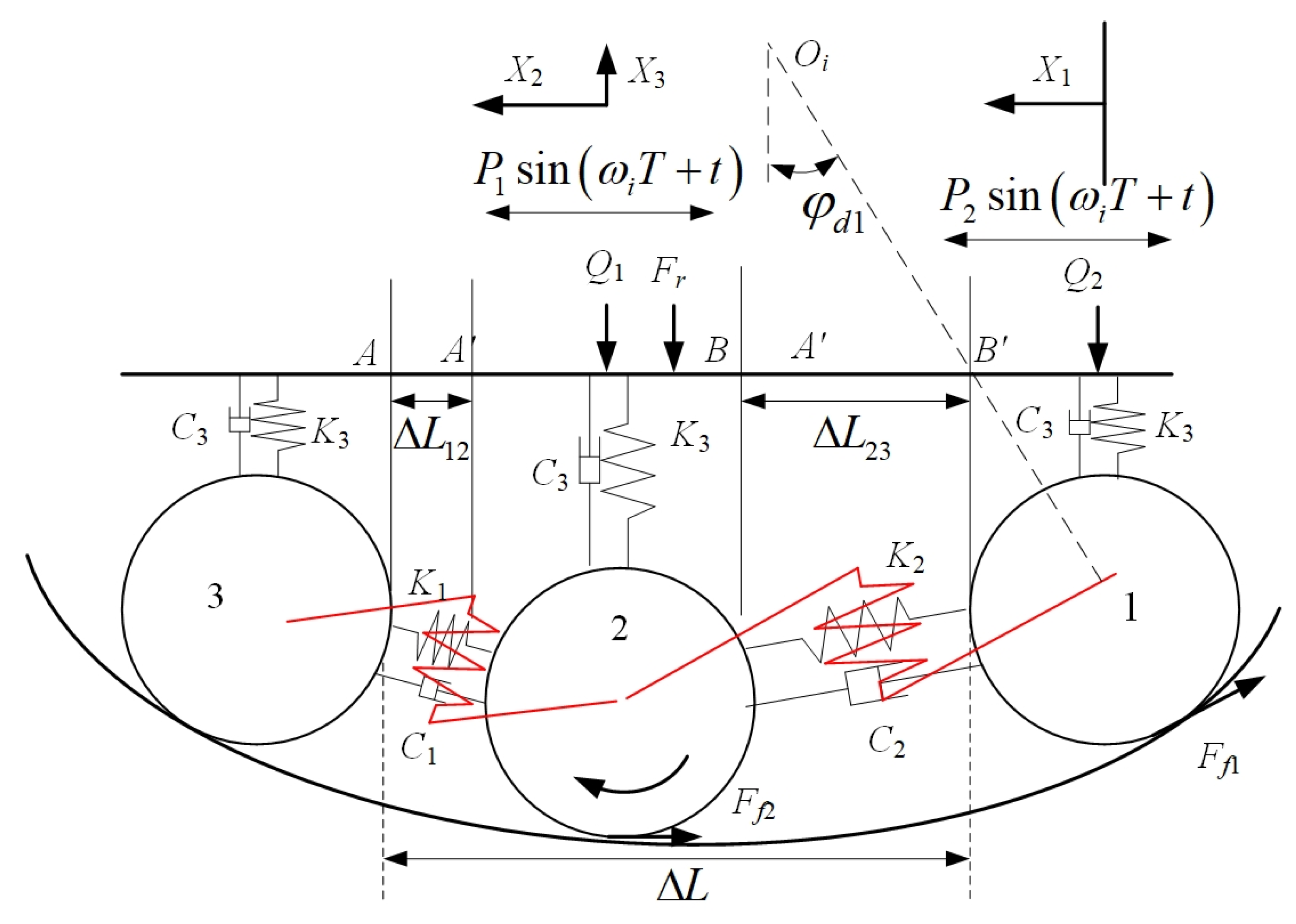
A random clearance ∆L exists between rolling elements No. 1 and No. 3, within which the motion of rolling element No. 2 is constrained. The random clearance ΔL is the uncertain relative spacing between adjacent rolling elements, which arises from the stochastic evolution of the dynamic system. Considering the angle of friction between rolling elements, the tangential force at the contact point causes the rolling element to spin, and adjacent rolling elements tend to twist around the contact point. The tangential force is simplified as a torsion spring model. Accounting for the ring–rolling element friction, the contact characteristics between adjacent rolling elements are simplified as a collision excitation system containing friction and random clearance. The model is shown in Figure 2. Three adjacent rolling elements (Nos. 1, 2, and 3) are equivalent to oscillators with masses M1, M2, and M1, respectively. The kinematic characteristics of rolling element No. 2 are mainly analyzed. The No. 1 and No. 3 rolling elements are equivalent to an integral oscillator with a mass of M1 = 2M2. The inner ring drives the rolling element via a friction force; the friction force is simplified as a simple harmonic force P sin(ωiT + t), which is related to the contact load and inner-ring speed.
The motion equation of No. 2 rolling element is
M 2 X ¨ 2 + C 1 X ˙ 2 + K 1 X 2 + C 2 X ˙ 2 X ˙ 1 + K 1 X 2 X 1 = F f 2 sin φ d 2 + P 1 sin ω i T + t M 1 X ¨ 1 + C 2 X ˙ 2 X ˙ 1 + K 2 X 2 X 1 = F f 1 sin φ d 1 + P 2 sin ω i T + t M 2 X ¨ 3 + C 3 X ˙ 3 + K 3 X 3 = Q 1
where Ff1 and Ff2 are the friction forces at the rolling-element/outer-ring interface. φd1 and φd2 are the angular positions of adjacent rolling elements No. 1 and No. 2. K3 is the stiffness coefficient at the rolling-element/outer-ring interface. C3 is the damping coefficient. K1 and K2 are the contact stiffnesses of adjacent rolling elements, and C1 and C2 are the damping coefficients. Perform dimensionless processing on the parameters in the equation.
The relative velocity of adjacent rolling elements before and after contact can be determined from the above equation. The motion form is defined by the relative velocity and clearance range: (1) There is no contact between adjacent rolling elements. (2) Within the constrained clearance, two rolling elements collide. (3) Two adjacent rolling elements come into contact but do not separate, and move together at the same revolution speed. The three kinematic behaviors are discussed as follows: When rolling element No. 2 receives an impact force from No. 1 that exceeds the ring friction, and provided that the speed of No. 2 is not zero, it undergoes accelerated sliding motion. At this time, when the minimum clearance between two adjacent rolling elements falls below the critical oil film value, Hertzian contact deformation occurs between the rolling elements. Both rolling elements are in motion, and the continuous contact model can be expressed as
x ˙ 1 = y 1 y ˙ 1 = f 1 1 μ m a 1 sin ω t + τ 2 ζ 1 + μ c 2 y 1 y 2 1 + μ k 1 x 1 x 2 x ˙ 2 = y 2 y ˙ 2 = f 2 a 2 sin ω t + τ 2 ζ 1 + μ c 2 y 2 y 1 μ m 1 + μ k 2 x 2 + 1 + μ k 1 x 1
When the relative displacement between adjacent rolling elements reaches the clearance limit, the elements come into contact, but their rotational speeds are unequal. A velocity jump occurs between them within an extremely short time interval, and the relative velocity reverses direction. The system enters the instantaneous collision stage, where the restitution coefficient model must be employed. At this point, there is also a collision between adjacent rolling elements, which can result in
μ m x ˙ 1 + + x ˙ 2 + = μ m x ˙ 1 + x ˙ 2 x ˙ 2 + x ˙ 1 + = R x ˙ 2 x ˙ 1
where x ˙ 1 + , x ˙ 1 , x ˙ 2 + and x ˙ 2 are the velocities of the rolling element before and after collision, respectively. R is the recovery coefficient; in this study, R is taken to be 0 R < 1 . The case R = 0 corresponds to a perfectly plastic collision (maximum dissipation), while R = 1 corresponds to a perfectly elastic collision.
The transient collision impact force between any adjacent rolling elements is determined by the continuous contact force method. Considering the position and posture of adjacent rolling elements and the collision velocities of rolling elements in different contact states. By combining Equations (10)–(12), the collision impact force Fim between adjacent rolling elements can be determined as
F i m = 1 + μ c 2 x ˙ 2 + 1 + μ k 2 x 2 1 + μ c 1 x ˙ 1 + 1 + μ k 1 x 1
Within the constraint clearance range, the No. 1 rolling element gradually moves closer to rolling element No. 2 and does not separate after contact. Instead, the two rolling elements rotate synchronously at the same speed. The adjacent rolling elements undergo frictional motion without any instantaneous impact force, so the revolution speed and acceleration of rolling elements No. 1 and No. 2 are the same at this stage. The vibration system becomes an oscillator with a mass of (2M2), and the dynamic equation can be described as
F 1 = a 1 sin ω t + τ μ k 2 l μ k 1 x 1 μ c 1 x ˙ 1 F f q q f 1 F 2 = a 2 sin ω t + τ μ k 2 l + F f q q f 2
F1 and F2 are the combined forces exerted on No. 1 and No. 2 rolling elements during the contact process, respectively.
Due to the identical speed and acceleration of the two rolling elements, the torsional friction force generated between adjacent rolling elements during synchronous motion can be determined based on the same combined force as
F f q q = μ m a 1 sin ω t + τ μ k 2 l μ k 1 x 1 μ c 1 x ˙ 1 f 1 + f 2 + μ k 2 l a 2 sin ω t + τ 1 + μ m
Based on the above analysis, the spatial position and relative motion velocities of adjacent rolling elements can be determined, the possible collision impact and friction states between them can be assessed using the principle of vibration collision. Combined with the bearing structure and the inter-rolling-element clearance, the collision impact force and torsional friction model for the rolling element can be developed. The torque model under collision and friction can be determined as
M f = R w F f q q
In addition to the instantaneous impact force between adjacent rolling elements, the nonlinear Hertzian contact force is determined by the rolling element’s position and velocity, while the relative position vector of adjacent rolling elements and the contact-point velocity model are formulated accordingly. The minimum gap between adjacent rolling elements indicates the contact state, and the interaction form is then determined by the relationship between the speeds of adjacent rolling elements.
Combined with Figure 1b, the relative position vectors of the jth and jth + 1 rolling elements in the azimuth coordinate system can be represented as
r b b i = T i a r b j i r b j + 1 i
The minimum surface clearance between adjacent rolling elements is calculated as
h 0 = r b b i D
By comparing the minimum clearance with the critical oil film thickness a, we can determine whether the rolling elements are in contact. When h0 > 4/3∆r, there is no interaction between adjacent rolling elements. When 4/3∆r > h0 > ∆r, there is no Hertzian contact deformation between adjacent rolling elements, but oil film dynamic pressure generated by the oil film. When h0 < ∆r, adjacent rolling elements undergo Hertzian contact deformation. The normal contact force of adjacent rolling elements under fluid dynamic pressure can be determined as
F b f n = U L φ 128 α r R z h
where L is combined with the contact geometry, and its numerical value is defined as L = 5.163, ϕ = 0.6, ar = 1, U is a dimensionless velocity parameter and is written as U = η 0 U i o 2 E .
Before the hydrodynamic contact force can be determined, the relative sliding velocity at the rolling-element contact point must be analyzed. The coordinates of any point within the contact circle are defined as (xg, 0, zg), and the location vectors of the contact point with respect to the centers of two adjacent spheres Ob are described as follows.
r g b g = x g , D / 2 , z g T r g p g = x g , D / 2 , z g T
With respect to the inertial coordinate system, the translational speeds of adjacent rolling elements are defined as v b j i x ˙ b j , r ˙ b j , θ ˙ b j and v b j + 1 i x ˙ b j + 1 , r ˙ b j + 1 , θ ˙ b j + 1 , and the rotational velocities of rolling bodies are defined as ω b j b ω b j x b , ω b j y b , ω b j z b and ω b j + 1 b ω b j + 1 x b , ω b j + 1 y b , ω b j + 1 z b . The sliding speeds of adjacent rolling elements at the contact points are calculated as
v g b g = T b g ω b j b × r g b g + T b g T b i v b j i v g p g = T p g ω b j + 1 b × r g p g + T p g T p i v b j + 1 i
where Tbg and Tpg denote the matrices transforming from the fixed body coordinate system to the spherical contact coordinate system, respectively.
Therefore, the relative sliding speed at the contact point is given as
v b p g = v g b g v g p g
When h0 ≤ ∆r, in addition to the lubricant action, the Hertzian force due to contact deformation and the damping force from hysteresis damping are also considered in the rolling element contact normal force. It can be expressed as
F b c n = K δ b p 3 / 2 + C n v b p 2 g
The adjacent-rolling-element contact force is then obtained as
F b n = F b f n Δ r < h 0 < 4 Δ r / 3 F b c n h 0 Δ r
After the normal contact force is determined, the frictional force between adjacent rolling elements can be obtained as
T j j + 1 x g = a a a 1 z / a 2 a 1 z / a 2 μ k q q x Δ T q q g d x d z T j j + 1 z g = a a a 1 x / a 2 a 1 x / a 2 μ k q q z Δ T q q g d z d x
where Δ T q q g is the frictional force at any point within the contact area; it can be expressed as Δ T q q g = 3 μ k q q F q q a 2 2 π 1 a x 2 a z 2 d z d x .
By integrating the incremental traction and moment over the contact ellipse, one can obtain the total force Fb and moment Mb exerted on the rolling element and the raceway, respectively.
F b q a = T b g F b q g = T b g T x , F b n , T y T M b q a = T b g r b g g × F b q g

2.4. Centrifugal Force and Drag Force of Rolling Element

The centrifugal force, caused by the rolling element’s high-speed revolution around the bearing center, must be considered; it can be given as
F c j = m b r b θ ˙ 2
The lubricant–air mixture produces a drag force that affects the rolling-element motion and can be expressed as
F d = 1 2 C D ρ A V 2
where CD, ρ and A are the drag coefficient, equivalent density of the lubricant–air mixture, and effective area in the translational direction, respectively:
A = 1 4 π D w 2

3. Cageless Bearing Dynamics Modeling and Solution Method

3.1. Cageless Bearing Dynamics Model

Considering the rolling-element–raceway contact forces, inter-rolling-element contact forces, drag force, and lubricant drag effect, and according to the force and moment interactions among rolling element components, the motion attitude of the rolling elements and the motion characteristics of the bearing inner ring are taken into account. Based on Eulerian kinematics theory, Eulerian equations of motion are established for each rolling element to describe its spatial motion. For each rolling element, the equation of motion is
x ¨ b j m b = F b r o x a + F b r i x a + F b q x a r ¨ b j m b = F b r o z a + F b r i z a + F b q i i + 1 z a + F b q i i 1 z a + m b r b j θ ˙ b j m b r b j θ ¨ = F b r o y a F b r i y a F b q i i + 1 y a F d 2 m b r ˙ b j θ ˙ b j + F b q i i 1 y a
The equation of rotational motion describing the characteristics of autorotation attitude can be represented as
I b ω ˙ x b j = M b r x i a + M b r x o a + M b q x a M e x a I b ω ˙ y b j = M b r y i a + M b r y o a + M b q y a M e y a + I b ω z b j θ ˙ b j I b ω ˙ z b j = M b r z i a + M b r z o a M e z a I b ω y b j θ ˙ b j + M b q y a
where mb is the mass of the rolling element, and I is the inertia moment vector of the rolling element; it can be written as follows I b = m b D w 2 / 10 .
Regarding the inner race motion, a 3-DOF motion model is established as follows.
m r x ¨ r = j = 1 14 T i c F r b i x j c + F a m r y ¨ r = j = 1 14 T i c F r b i y j c m r z ¨ r = j = 1 14 T i c F r b i z j c + F r I r θ ¨ r y = j = 1 14 T r a M r b i y a I r θ ¨ r z = j = 1 14 T r a M r b i z a
where Ir is the moment of inertia of the inner ring, θry is the angle of deflection of the inner circle around the y-axis, θrz is the angle of deflection of the inner circle around the z-axis.

3.2. Numerical Simulation Procedure

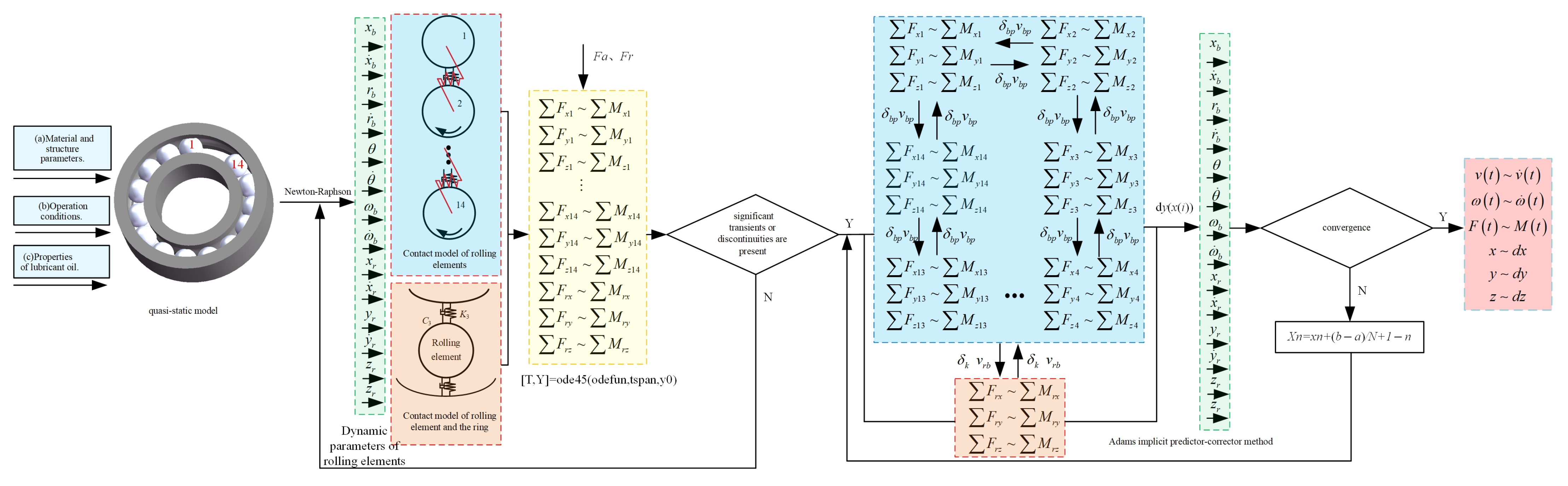
The initial condition for the dynamic model is the static state of the cageless bearing (Figure 3). Under gravity, the rolling elements are in mutual contact, while the first and 14th are separated and specially designated. Then, the initial parameters (material and structural parameters, operating conditions, lubricant properties) are considered. Specifically, the present model is established under the assumptions of isothermal elastohydrodynamic lubrication and fully flooded conditions. The lubricant density and drag coefficient are employed to evaluate the fluid resistance, while viscosity η 0 and the viscosity-pressure coefficient α are used to calculate the hydrodynamic contact force. These parameters are substituted into the component interaction model, and the Newton-Raphson scheme is first employed to solve the quasi-static model to obtain the force, torque, linear velocity, and angular velocity in the corresponding coordinate system. The impact collision or continuous friction between adjacent rolling elements leads to significant differences in the results (velocity, acceleration, and force) of each iteration compared with the previous step. This requires reducing the step size to improve solution accuracy through the Runge–Kutta scheme. We formulate the dynamic equations for the rolling element and ring, together with the contact equation, and then substitute the force, torque, linear velocity, and angular velocity into them. To simplify interpolation for arbitrary steps, the Adams-GSTIFF variable-step integration algorithm [23] in the mean-difference form proposed by Gupta is adopted. This algorithm triggers adaptive step-size adjustment by detecting abrupt changes in contact forces. This mechanism, together with local truncation error control, ensures solution accuracy and computational stability at contact discontinuities. The model was solved using MATLAB 2019b.
The structural parameters and material properties of the cageless bearing, along with the initial values and lubrication characteristics for the dynamic calculation, are shown in Table 1. Three typical bearing speeds (n = 1800, 3000, and 6000 rpm) and three load scenarios (pure axial and combined) are used in the simulations, based on the actual operating conditions of motorized spindle bearings.

4. Kinematic Characteristics Analysis of Cageless Bearings

Before presenting the kinematic analysis, it is necessary to verify that the numerical results are independent of the solver settings. A convergence test was conducted at 3000 rpm and 500 N. Two sets of simulations were performed: one with the original settings and another with tightened tolerances and a halved maximum step size. The predicted slip rate curves from the two simulations are essentially coincident, with the maximum slip rate changing only slightly from 7.8% to 7.2% when the step size is reduced. This confirms that the slip velocity results are not significantly affected by changes in the numerical settings, and the results presented below are numerically converged and reliable.
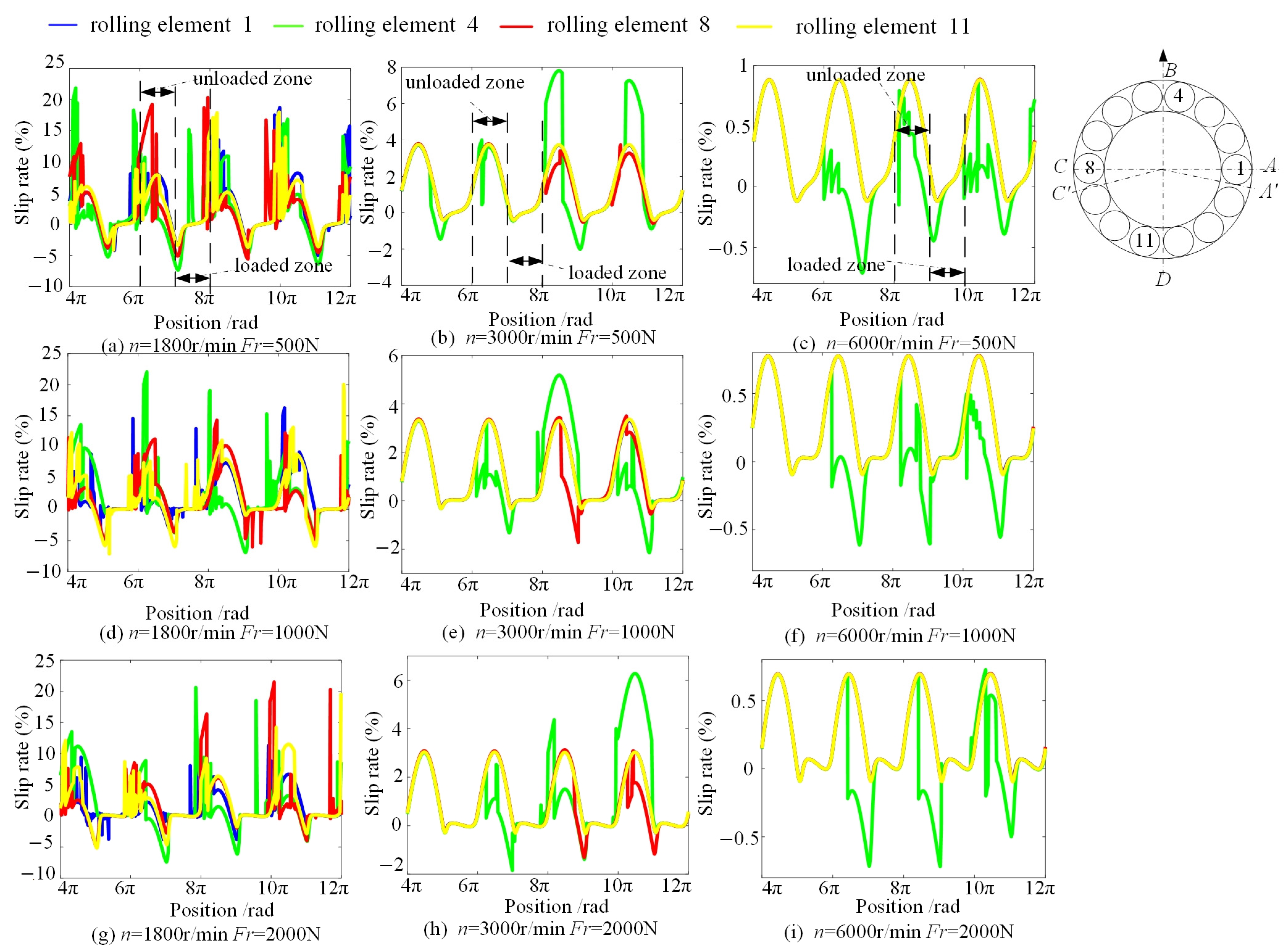
The motion trend of each rolling element varies randomly during operation. Therefore, while ensuring generality, four rolling elements with different initial positions among the 14 rolling elements were selected for analysis and numbered 1, 4, 8, and 11. For the cageless bearing, only a constant radial load (Fr = 500 N, 1000 N, 2000 N); Figure 4 presents the slippage rate of the rolling elements at various rotational speeds.
The initial positions of the four rolling elements 1, 4, 8, and 11 are located at the junction of the bearing and unloaded zone (point A), the top of the unloaded zone (point B), the unloaded zone boundary and loaded zone (point C), and the maximum load in the loaded zone (point D). Sliding is more severe at 1800 r/min, whereas at 3000 and 6000 r/min, elements 1, 8, and 11 exhibit consistent slip rates. Thus, initial placement in the unloaded zone facilitates slip occurrence. The maximum slip rates in the unloaded zone are 22%, 7.8%, and 0.89%, respectively, while those in the loaded zone are −6%, −0.5%, and −0.1%, respectively. In the engineering simplification adopted in this study, the theoretical speed is calculated based on the pure-rolling geometric relationship, and the slip rates in both the loaded and unloaded zones adopt the same theoretical speed as a reference to maintain consistency across all operating conditions. As the rotational speed increases, rolling-element sliding weakens during revolution. According to Equation (27), the centrifugal force increases from 0.726 N at 1800 rpm to 2.017 N at 3000 rpm and 8.069 N at 6000 rpm. Based on Hertzian contact theory and the friction model of Sakaguchi [22], the frictional driving force at the rolling element–raceway interface increases from 7.79 N at 1800 rpm to 16.31 N at 6000 rpm. This indicates that the increase in rotational speed enhances the frictional driving force, thereby suppressing skidding and impact events among the rolling elements. Consequently, the reduction in slip rate is attributed to the increased friction caused by the rising centrifugal force. Clearly, the slip rate of the cageless bearing is significantly reduced above 3000 r/min, which is consistent with the literature [24]. As the radial load increases, the slip-rate range barely changes, implying that rotational speed is the governing factor. In contrast, the slip rate of rolling elements in the unloaded zone is greater than that of the loaded zone.
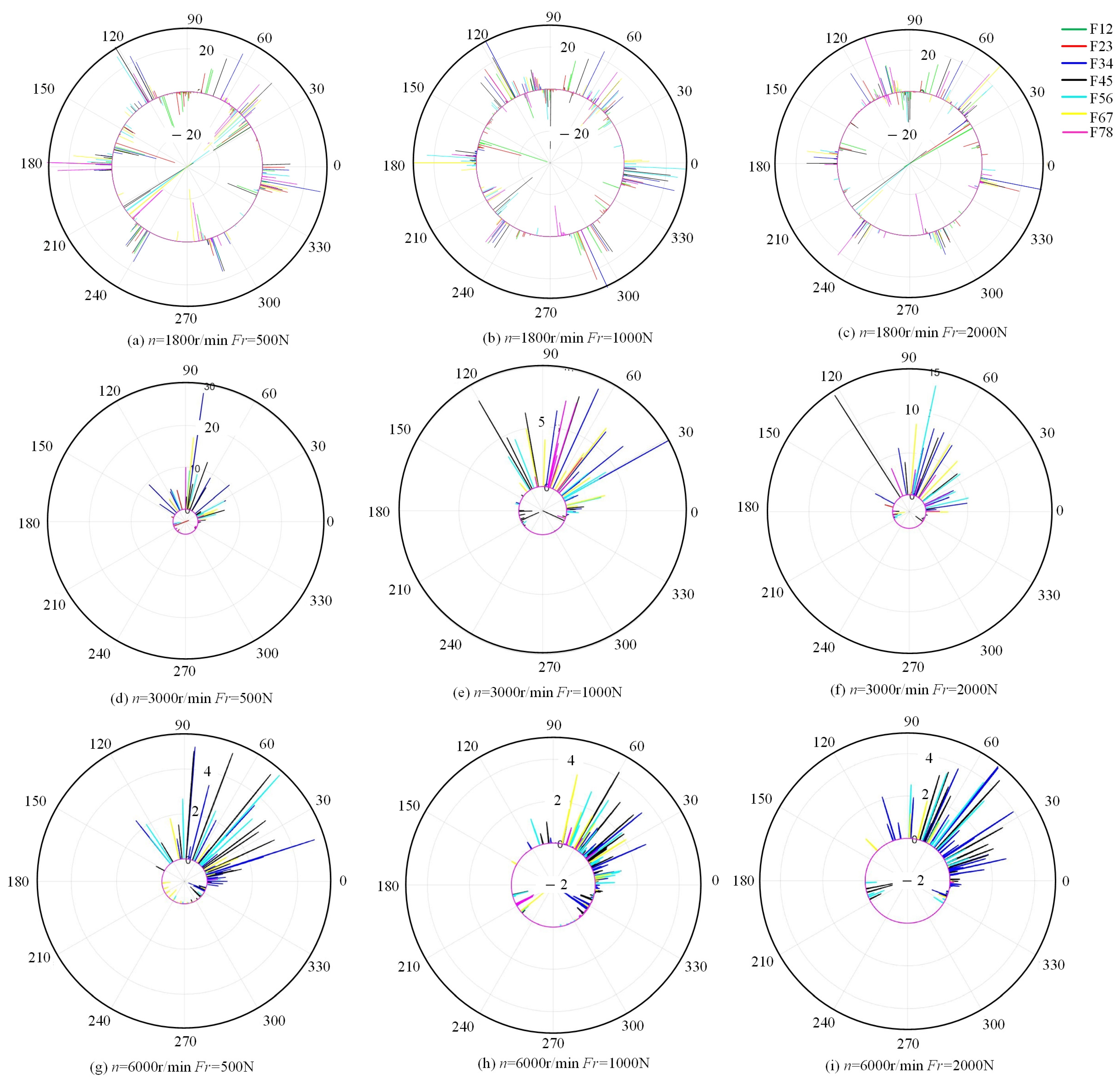
To describe the relationship between the sudden change in revolution speed and the locations where collisions occur, polar coordinates were used to depict the contact force distribution among adjacent rolling elements within 12 revolution cycles under different operating conditions, as shown in Figure 5. At speeds of 3000 r/min and 6000 r/min, the contact area between adjacent rolling elements is primarily located in the unloaded zone, and the collision frequency is less than 1800 r/min. Within the loaded zone, there is almost no collision within the angular position range of 240–300°. The collision impact force between adjacent rolling elements in the unloaded zone is positive, indicating that the rear one drives the front one to move. In the loaded zone, the contact force is negative, and the rear rolling element is blocked by the front one. However, the amplitude of the collision impact force is smaller than that in the unloaded zone, and under the same radial load, as the bearing rotates faster, the amplitude of the collision impact force decreases.
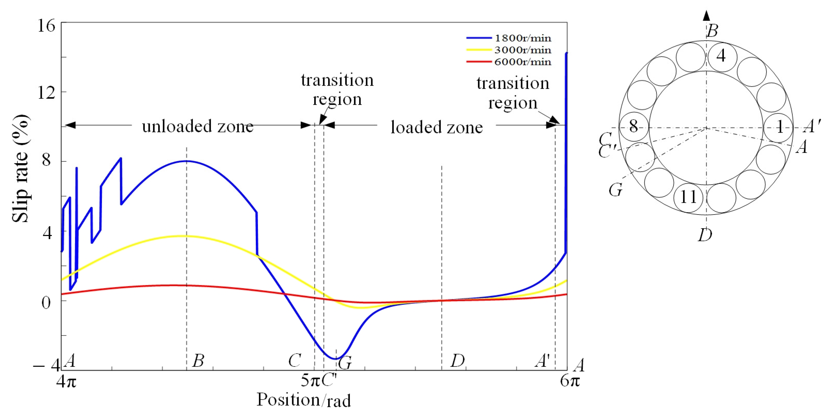
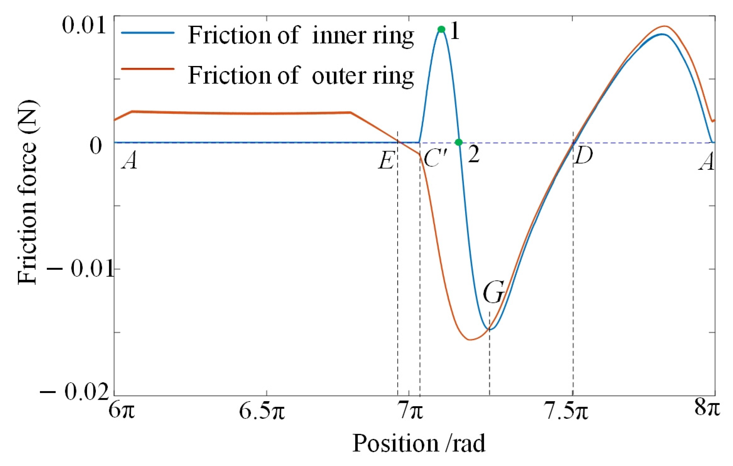
To further analyze the dynamic behavior within one cycle, the slip rate of rolling element 1 over one orbital period is shown in Figure 6. The slip rate is the relative difference between a rolling element’s actual and theoretical revolution speeds. In the first half of the unloaded zone (AB section), the component of gravity acting on the rolling elements opposes the linear velocity. Because the rolling element is in the deceleration “climbing” stage, its revolution speed gradually falls below the theoretical speed, reaching a minimum at point B. Under gravity, the revolution speed of the rolling element gradually increases. When the rolling element moves to point C′, it re-engages with both raceways simultaneously, where frictional forces are present. Accounting for gravity, the rolling element’s speed progressively decreases until it moves out of the loaded zone (point A). During this process, when the rolling element reaches point D, it enters pure rolling with a slip rate of 0. As the rolling element transitions from the loaded to the unloaded zone (AA section), its speed decreases more rapidly. This is because the rolling element is no longer driven by inner-ring friction; the slip rate increases, and it reciprocates multiple cycles. As the rolling element transitions from the loaded zone into the unloaded zone (section AB), the slip rate exhibits multiple abrupt changes. This is caused by the relatively small centrifugal force, which leads to high-frequency intermittent contacts between rolling element 1 and its adjacent rolling elements.
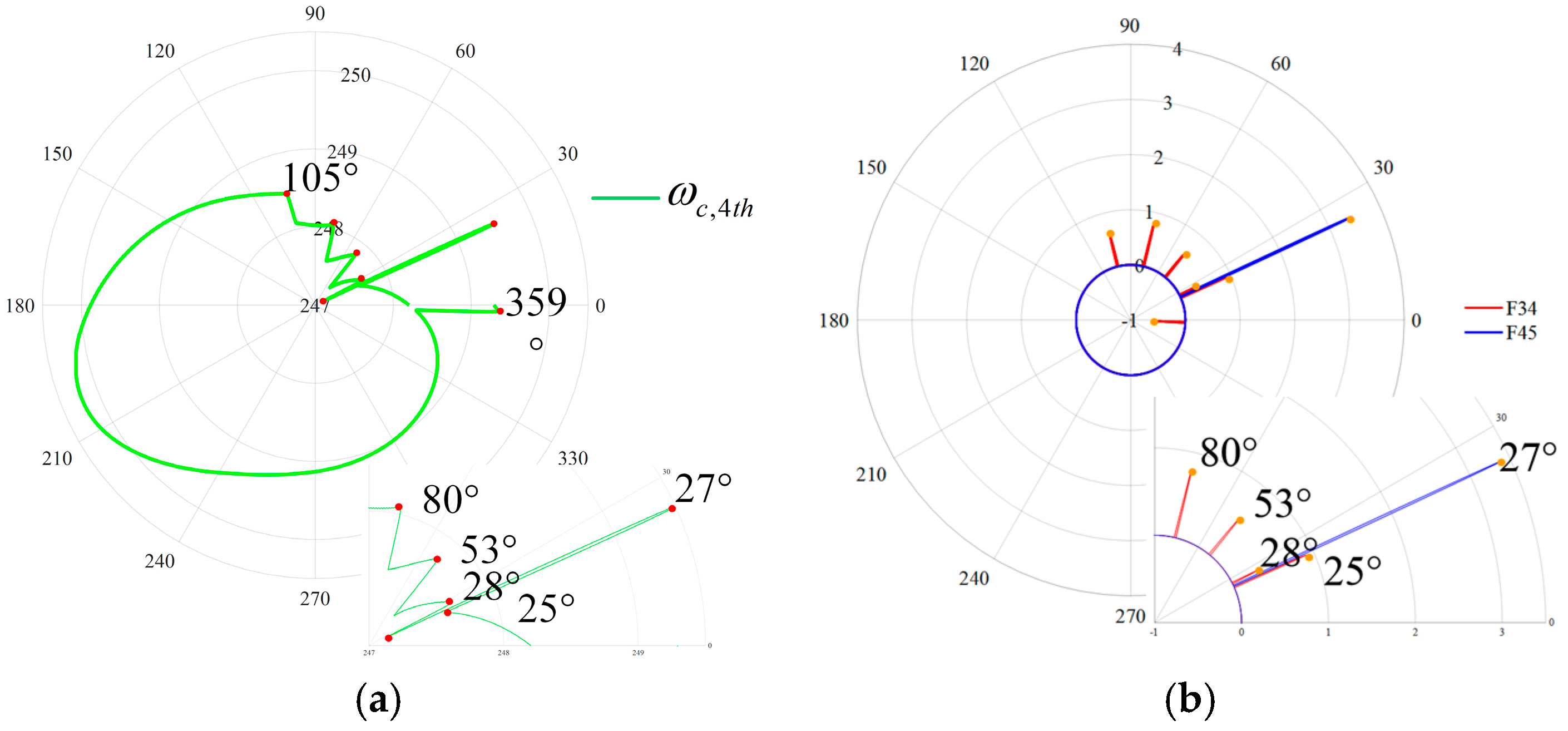
To confirm the slippage-collision relationship, we analyzed three adjacent rolling elements (Nos. 3, 4, and 5) and obtained their angular velocities and contact forces. As shown in Figure 7a, when rolling element No. 4 is located at angular positions of 25°, 27°, 28°, 53°, and 80°, its velocity undergoes abrupt changes. By comparing with Figure 7b, it can be observed that at these four positions, rolling element No. 4 is subjected to both the driving force applied by rolling element No. 3 and the resistive force applied by rolling element No. 5. This leads to random collisions between rolling element No. 4 and the other rolling elements, with the occurrences predominantly observed within the transition zone and the unloaded zone.
Figure 8 illustrates the influence of different operating conditions on the rolling element. Since the bearing is subjected solely to radial load, only the angular velocity in the x-direction is considered for analysis. As the load increases, the friction torque rises from 0.059 N·m to 0.236 N·m. According to Equation (31), the augmented net torque enhances the rolling element’s disturbance rejection capability against speed fluctuations, thereby attenuating the amplitude of spinning angular velocity variation. Rotational speed elevation leads to a quadratic increase in centrifugal force (Equation (27)), raising the friction torque in the unloaded zone from 0.000276 N·m to 0.00307 N·m. Concurrently, at elevated speeds, the oil film stabilizes under EHL conditions (Equation (6)), and the intensified spinning inertia effect (Equation (31)) further suppresses angular velocity fluctuations. The synergistic effect of these mechanisms confirms that the amplitude of spinning angular velocity variation diminishes monotonically with increasing load and rotational speed. Compared to the loaded zone, the spin angular velocity in the unloaded zone is larger. The variation in spin angular velocity of the rolling element arises from the friction torque exerted by the raceway. Thus, the spin angular velocity in the loaded zone is stable. With increasing inner ring rotational speed, the change in spin angular velocity gradually decreases.
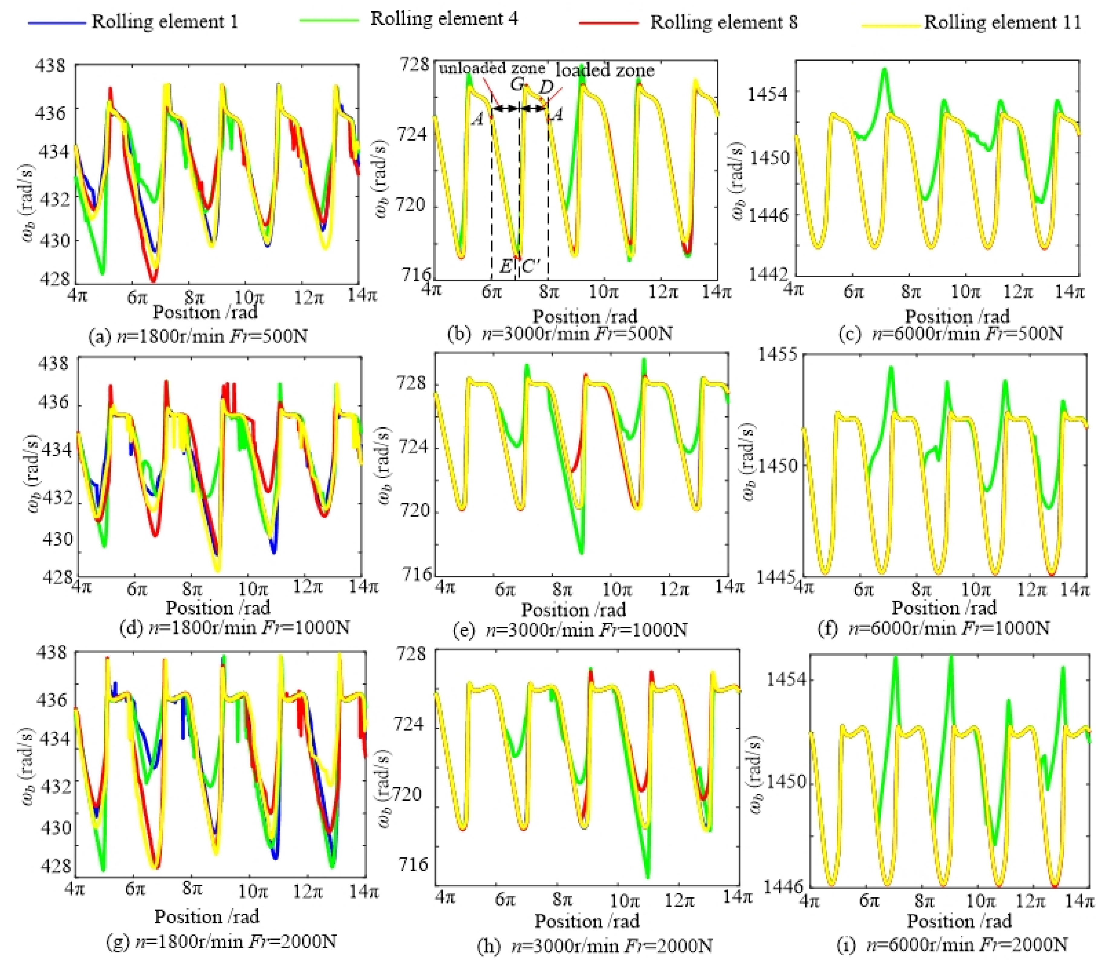
One revolution period is selected from Figure 8b to analyze the spin behavior of the 14 rolling elements. Figure 9 mainly presents results for rolling elements 1, 4, 8, and 11, while the remaining 10 rolling elements are shown as gray lines. In the unloaded zone, the rotational velocity of the rolling element initially decreases, then slightly increase as it approaches the loaded zone. In the transition zone, the spin angular velocity increases sharply. At the bottom of the loaded zone (the position of maximum radial load), the rotational velocity reaches the theoretical value under pure rolling conditions. Upon entering the unloaded zone, the rotational velocity gradually decreases. The first four rolling elements on the right side of the unloaded zone suddenly change their motion and climb from rest during inner-ring rotation. They tend to accumulate under the action of gravity components. As a result, due to the accumulation of slip contact during the initial movement, they slip severely in subsequent movements, and the rolling element–ring friction remains low. The angular velocity of their rotational motion also varies randomly with slip.
Figure 9 and Figure 10 show that as the rolling element moves into the unloaded zone (section AE), it is no longer in contact with the inner ring and is only hindered by the outer-ring friction force, which slows it down. The friction direction of the outer ring is the same as the rotation direction, driving the rolling element to gradually accelerate its rotation in section EG. The spin angular velocity increases sharply to its maximum at point G. Subsequently, opposing the motion, the friction torque of the inner and outer rings decelerates the rotation of the rolling element (section GA).
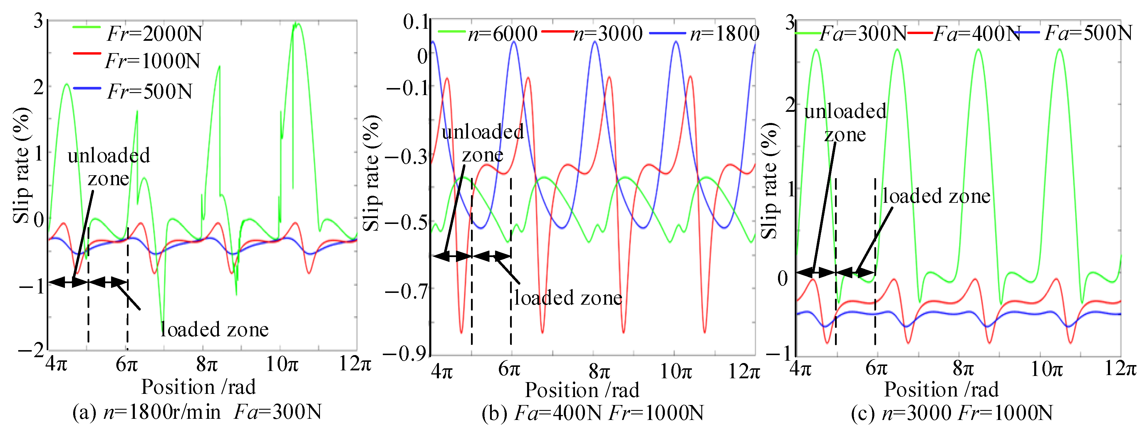
Among axial load, radial load, and rotational speed, rotational speed has the least influence on bearing slip, as shown in Figure 11. As the radial load increases, the inner ring displaces further in the direction of the applied load. The unloaded zone thereby expands, and the frictional driving force provided by the inner ring becomes insufficient. At lower rotational speeds, rolling elements may collide with each other due to gravity within the unloaded zone, inducing slip (Figure 11a). As the inner-ring angular speed increases, the rolling elements experience greater centrifugal force, resulting in increased friction with the outer ring and a consequent reduction in slip (Figure 11b). A larger axial load generates a greater normal force through the contact angle between the inner/outer rings and the rolling elements, thereby increasing frictional force in the direction of motion and making slip less likely (Figure 11c). The areas with severe slip remain the unloaded zone; as the radial load increases and the axial load decreases, the slip of the rolling elements increases.
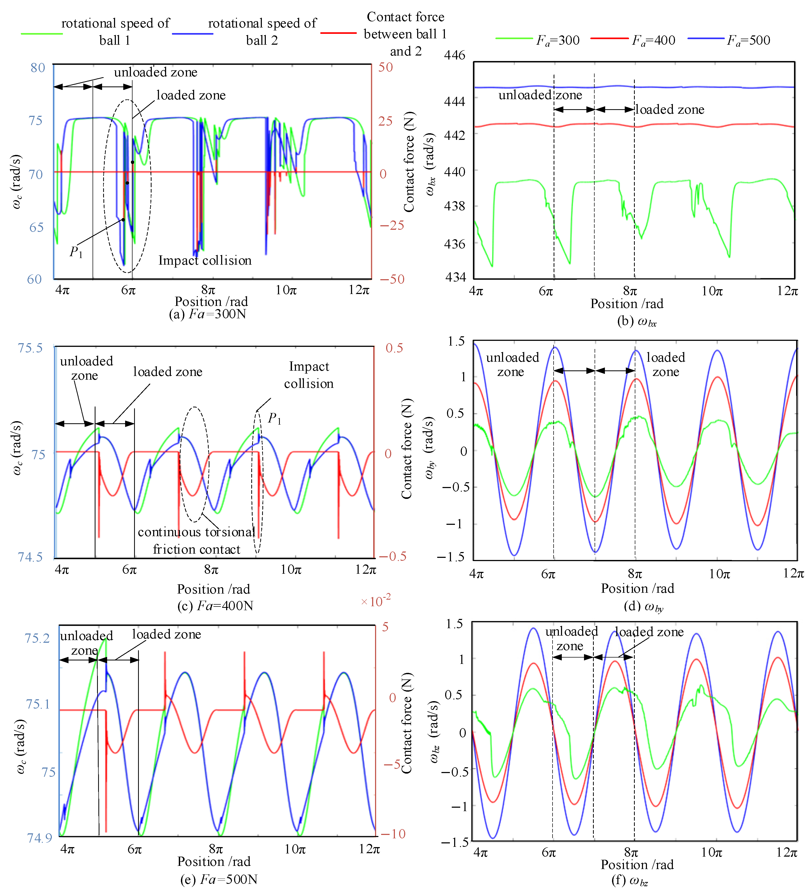
Under combined load, the contact forces and motion characteristics of adjacent rolling elements are illustrated in Figure 12. Figure 12a,c,e depict the correlation between the rolling-element revolution and the contact forces. When the friction force between rolling elements 1 and 2 suddenly changes from 0 to P 1 , the velocity of rolling element 1 decreases instantly, while that of rolling element 2 increases. This indicates that rolling element 2 is chasing rolling element 1 at this moment. The contact force takes the form of an impact collision force. After the impact collision, the adjacent rolling elements continue to move at the same speed, and the contact form becomes continuous torsional friction. Thus, the motion of adjacent rolling elements involves both impact collision and torsional friction, which occur randomly under combined loads. As the axial load increases, continuous torsional friction contact is more likely to occur. Figure 12b,d,f display the rotational attitude of the rolling elements under combined loads, in which the three velocity components and the contact angle with the raceway all increase with the axial load.
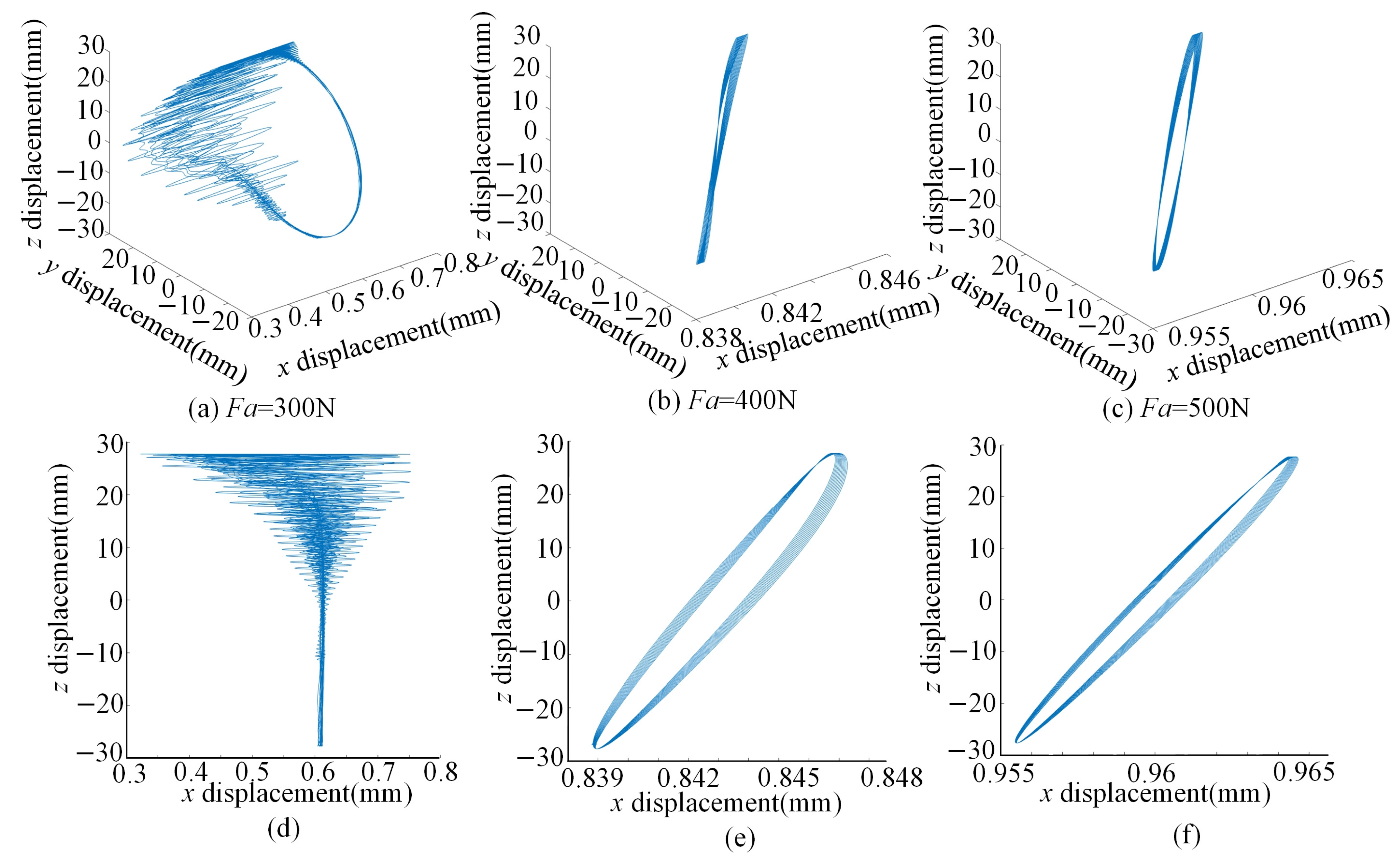
Figure 13 illustrates the motion characteristics of the rolling element through the trajectory of the contact point. When the axial load is small, the swing angle of the contact trajectory increases, and the rotation exhibits randomness. Due to the decrease in the rotation angular velocity component ωbx, the revolution velocity decreases, which leads to random contact collisions. The swing angle of the contact trajectory decreases as the axial load rises, and its rotation attitude is more stable. However, as the spin angular velocity components ωby and ωbz, increase, the spin motion and gyroscopic motion between adjacent rolling elements are more pronounced, resulting in friction. Collisions readily occur in the unloaded zone, while friction readily occurs in the loaded zone.
Therefore, the above results indicate that the adjacent-rolling-element contact force is primarily dominated by impact collision forces under pure radial loading, whereas under combined loading, both impact collision and torsional friction forces are present. The impact collision induces sliding, while torsional friction causes spin and gyroscopic motion. The impact of rotational speed on slip is more significant than that of radial load. The lower the rotational speed, the more severe the slip is, and the more readily the rolling elements contact and accumulate. Continuous friction caused by excessive axial load may, under conditions of high sliding speed or prolonged duration, lead to frictional heat generation and accelerated wear. Likewise, the friction torque, gyroscopic motion, and spin motions are theoretically expected to contribute to wear progression. These phenomena are more pronounced in the unloaded zone. It is apparently indicated that contact and accumulation of rolling elements are also concentrated in the unloaded zone.
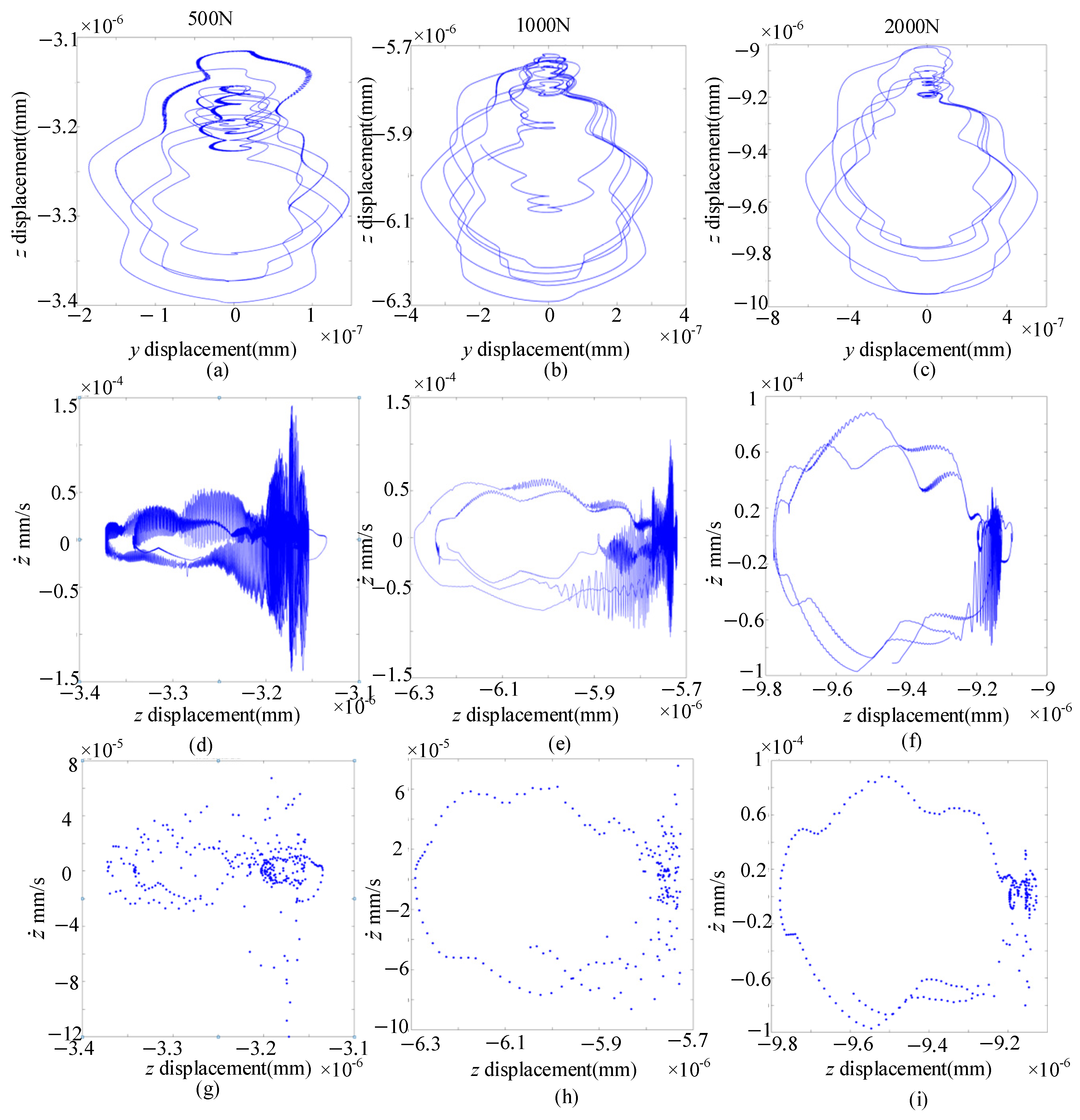
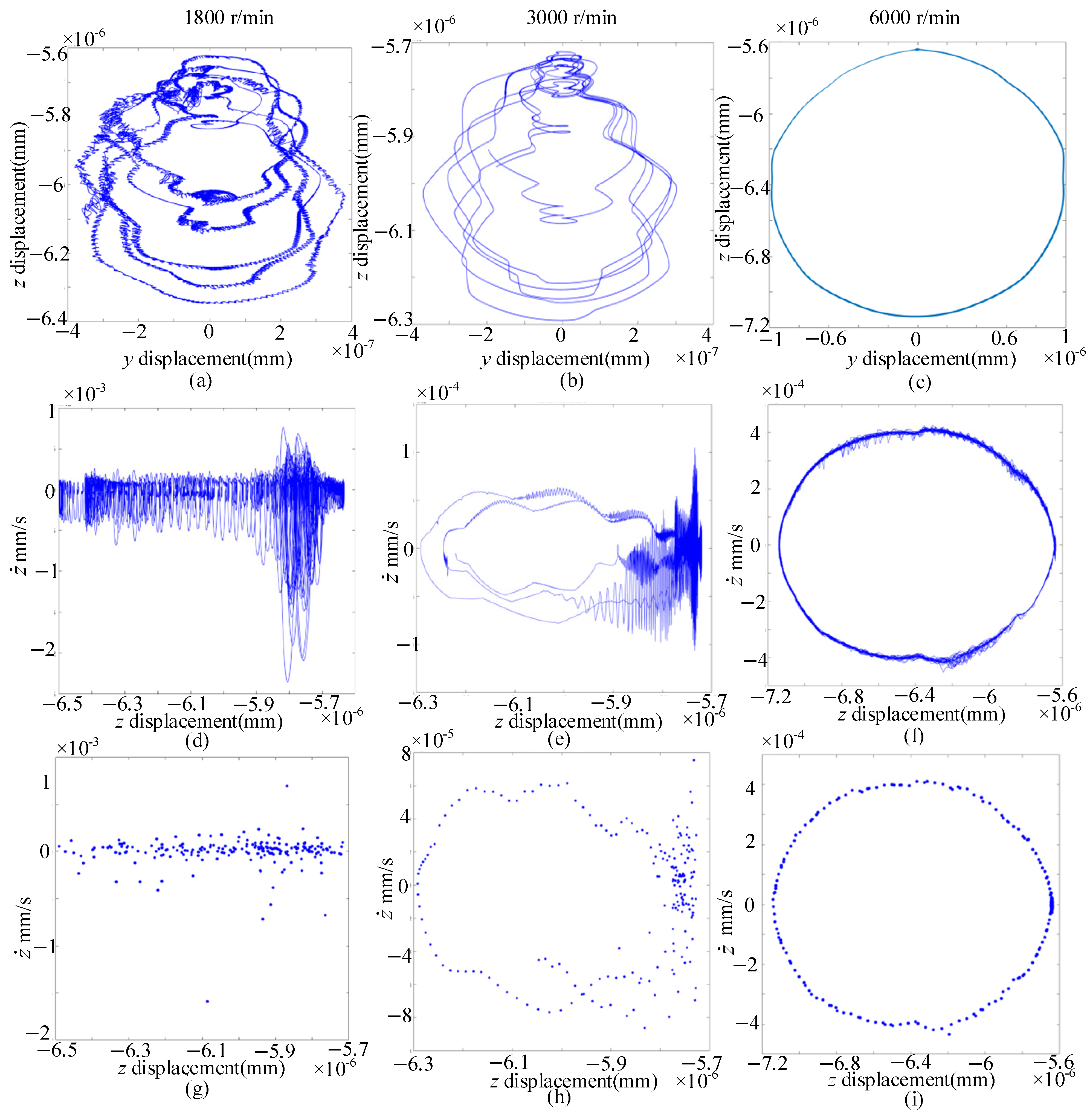
Cageless bearing system stability depends on adjacent rolling-element collisions, which are analyzed using a phase plane diagram, a Poincaré section map, and the inner ring trajectory in the time domain. Figure 14 shows the influence of different rotating speeds.
At 1800 r/min, the rolling element slips severely and causes irregular collisions, resulting in an uneven distribution. The center trajectory of the inner circle (Figure 14a) consists of irregular dynamic curves formed by the overlapping of multiple non-closed quasi-circular trajectories. The phase diagram of the inner circle (Figure 14d) is a non-closed curve formed by the superposition of multiple quasi-elliptical curves, corresponding to the Poincaré section map (Figure 14g), which consists of numerous scattered points that are disorderly distributed without forming a closed curve. This indicates that the bearing is in an unstable, aperiodic dynamic state. As the speed increases, the trajectory of the bearing inner ring is shown in Figure 14c as a closed curve band, and the corresponding Poincaré section map (Figure 14f) is represented as a closed curve composed of a finite point set. It is found that the cageless bearing changes from an aperiodic dynamic state to a quasi-periodic state at this time.
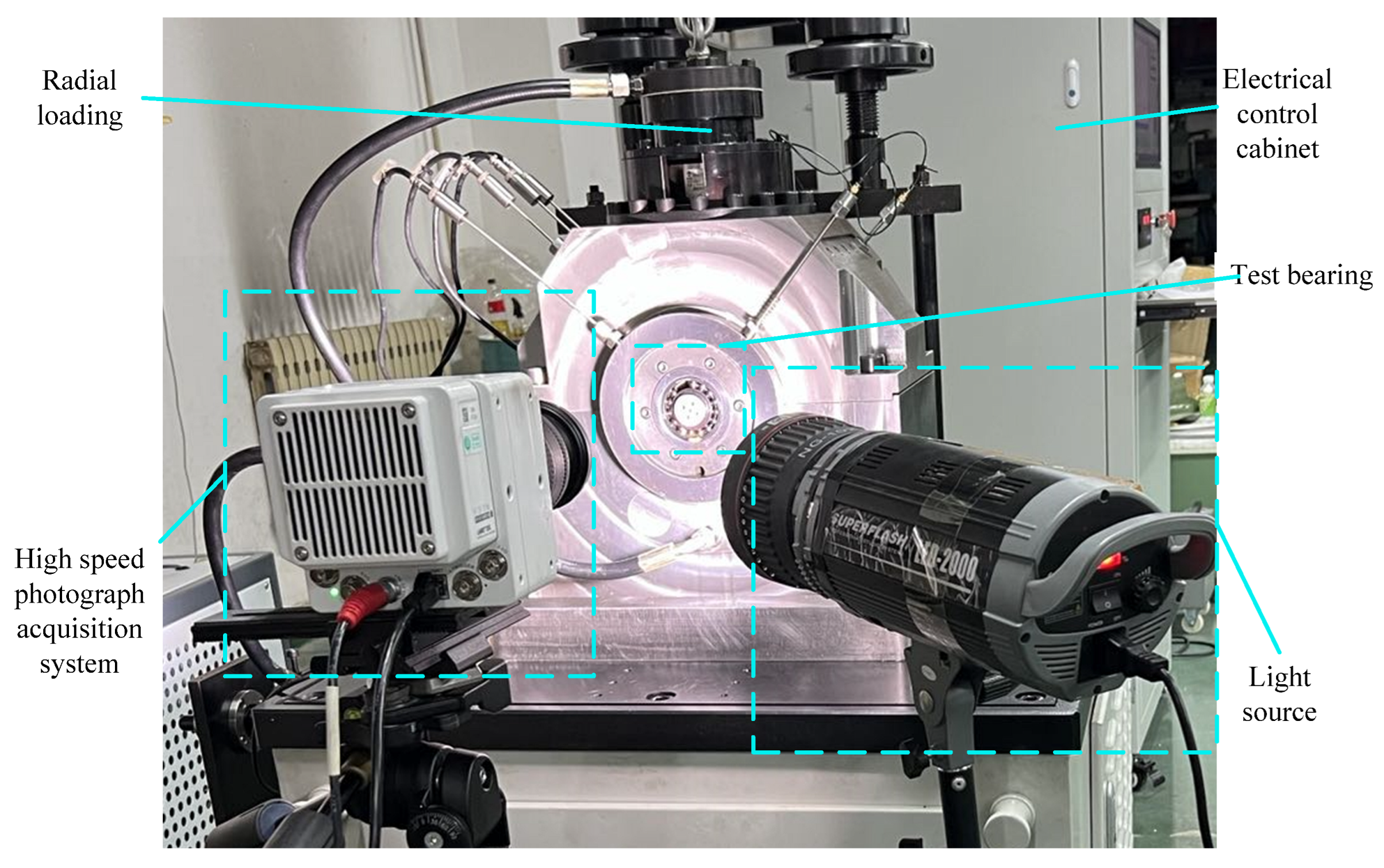
Figure 15 shows the influence of different radial loads. An increase in radial load results in a greater vertical (z-axis) displacement of the inner ring (Figure 15a–c), while its horizontal (y-axis) displacement remains essentially constant. The center trajectory of the inner ring gradually changes from aperiodic to repetitive. The phase diagrams (Figure 15d–f) are all aperiodic and non-closed curves. As the radial load increases, the mapping points of the Poincaré section map (Figure 15g–i) decrease gradually and become geometric segments composed of dense points. With increasing radial load, the amplitude of the aperiodic motion of the system decreases significantly, the fluctuation range of the inner-ring trajectory contracts, and the fluctuation amplitudes of collision forces and slip rates are reduced. This indicates that, while the complex dynamic behavior is maintained, the dynamic response tends toward relative stability, which corresponds to the sliding and collision characteristics of rolling elements in Figure 12. For kinematic characteristic analysis, a high-speed camera is employed to capture the trajectory of the rolling element. The experimental device for the motion of a cageless bearing is shown in Figure 16. The high-speed camera used in the experiments is a VEO-710-L (Phantom/ Wayne, NJ, USA), equipped with a Nikon (NIKON CORPORATION, Tokyo, Japan) 24–85 mm f/2.8–4 D AF Zoom lens. The frame rate is set to 10,000 FPS, with an image resolution of 1280 × 800 pixels and an exposure time of 10 μs. The field of view is 102 mm × 64 mm, corresponding to a spatial resolution of approximately 12.5 pixels/mm. The coating applied to the rolling element surfaces is a black spray coating. This coating is applied solely to the rolling element surfaces for optical tracking purposes to enhance image recognition accuracy, and is not applied to the inner or outer raceway surfaces.
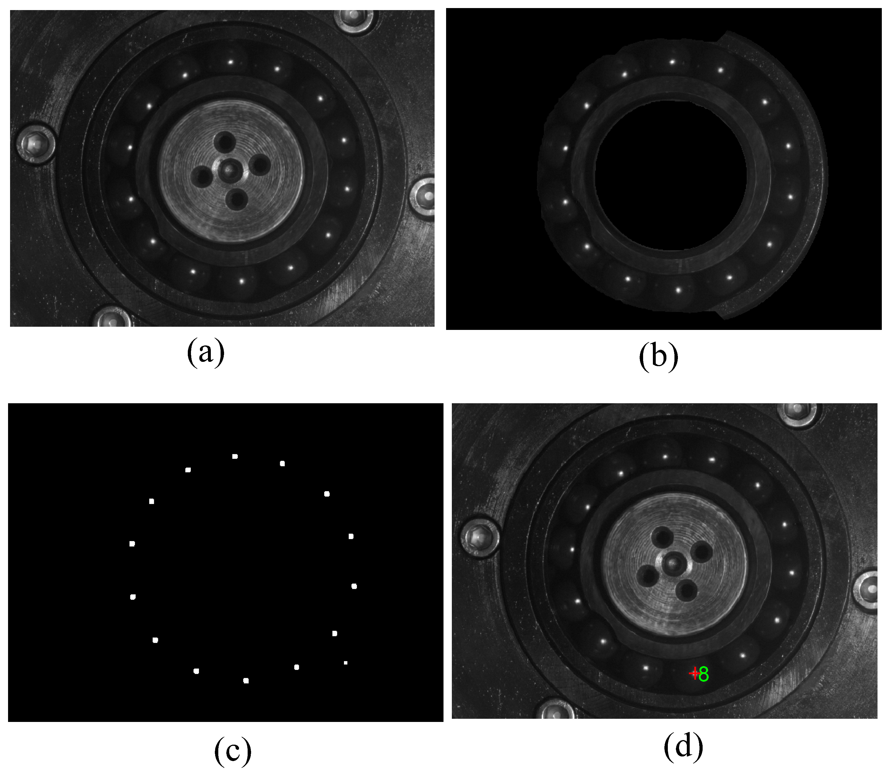
Given the available experimental space for positioning the light sources and camera, the light sources and high-speed cameras are placed at the front end of the test bearing end face, and the camera is calibrated. Owing to the light-reflecting properties of metal rolling elements, capturing their motion with a camera poses significant challenges. Hence, this article selects rolling elements with black surface coatings for testing. Based on the principles of incident light reflection and refraction, the surface reflective highlights of the rolling element are recorded in Figure 17a. For accurate identification of the reflective points on the rolling elements, the connected domain of the image is calibrated and cropped to determine the bearing contour, as shown in Figure 17b. The image preprocessing employs a two-stage binarization strategy. Global binarization combined with a connected-component area-threshold criterion is applied to extract the bearing contour and filter out metallic reflection noise. Local binarization is then used to focus on the reflective point regions on the rolling element surfaces, followed by dilation and filling operations. To identify the trajectory of the reflective points on the rolling elements, a thresholding method is used to binarize the image, and the marked points are expanded, as depicted in Figure 17c. The identification of the reflective point markers is combined with the frame number and shooting time of the high-speed photography images, and the spatial coordinate data of the marked points of the rolling element are collected once per frame, as shown in Figure 17d. The center coordinate values of the 14 rolling elements at any position are collected.
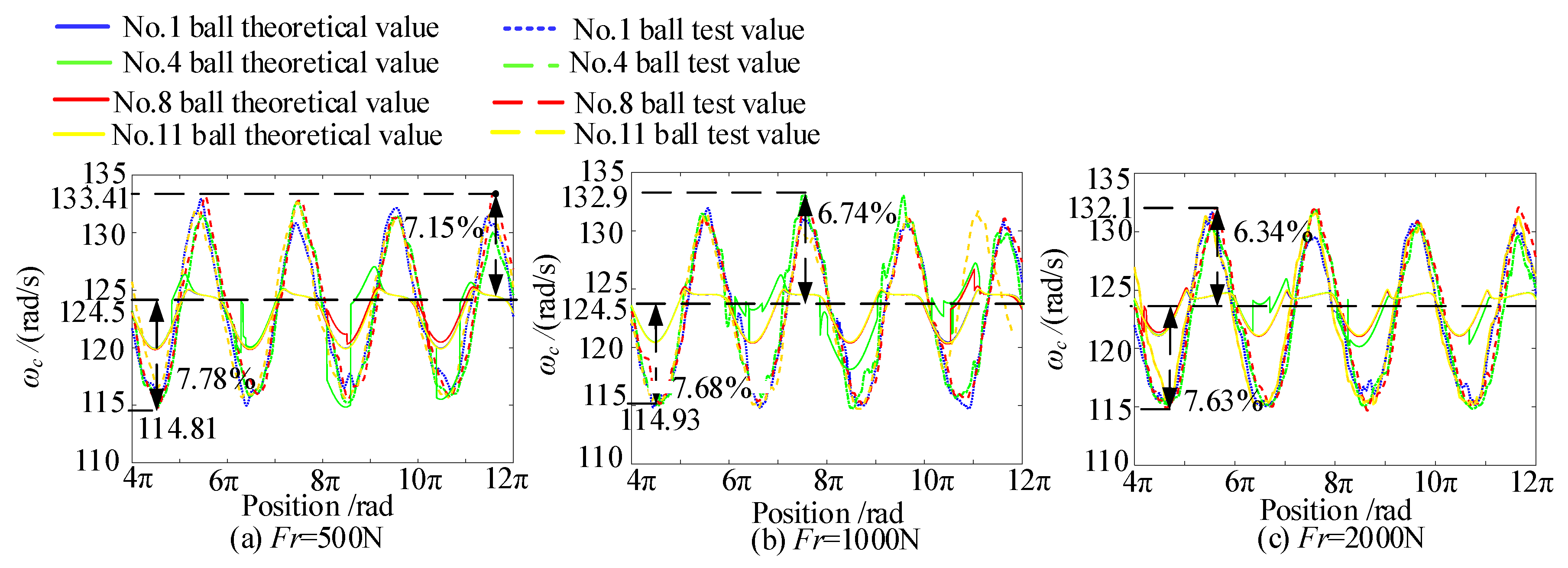
Figure 18 compares the experimental and theoretical revolution speeds of the rolling element under radial loads of 500, 1000, and 2000 N at 3000 r/min. The measured revolution speed first decreases and then increases, which is similar to the trend predicted by the theoretical model. Due to the large bearing clearance during the experiment, the range of the loaded zone decreases under radial load, causing the rolling element to continuously accelerate under the combined action of gravity and the inner ring, and then decelerate after reaching the position of the maximum radial load. Radial load reduces the revolution-speed fluctuation of the rolling element. The maximum slip rate decreases from 7.15% under a radial load of 500 N to 6.74% under a load of 1000 N. With the radial load increased to 2000 N, the slip rate is 6.34%, and the slip rates in the unloaded zone are 7.87%, 7.68%, and 7.63%, respectively. It follows that increasing the radial load is beneficial for reducing bearing slip. As the radial load increases, the contact area between the rolling element and both rings enlarges. The frictional forces provided by both rings work together to better ensure the pure rolling motion tendency of the rolling element.
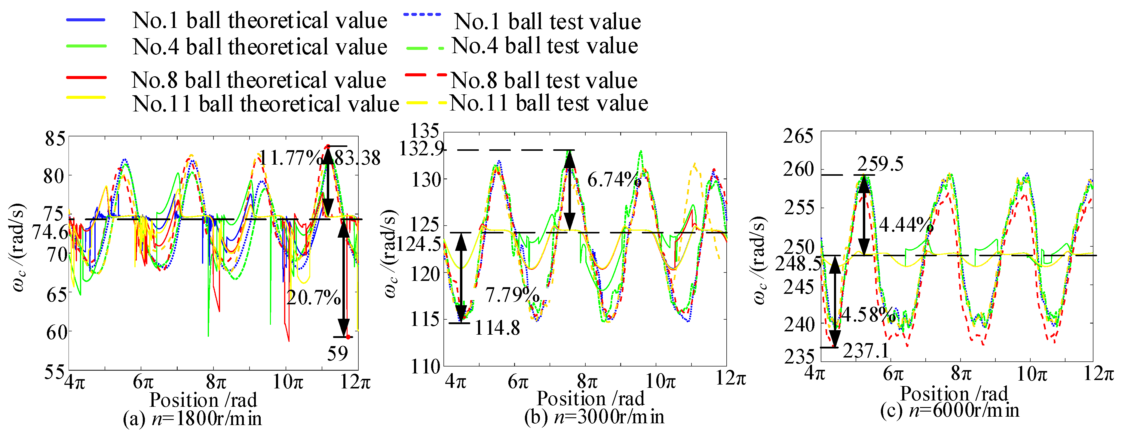
The experimental and theoretical revolution speeds of the rolling element under a 500 N radial load and inner-ring speeds of 1800, 3000, and 6000 r/min are shown in Figure 19. According to the experimental results, as the bearing speed increases, the fluctuation range of the rolling element’s revolution speed decreases. At 3000 r/min, the maximum slip rate of the rolling element drops from 11.77% to 6.74%. When the speed continues to increase to 6000 r/min, the slip rate is 4.44%, and the slip rates in the unloaded zone are 20.7%, 7.79%, and 4.58%, respectively. This indicates that high rotational speed conditions are beneficial for reducing bearing slip. Figure 18 and Figure 19 show that the bearing inner ring speed, rather than radial load, has a more significant impact on slip. Rotational speed is the dominant factor affecting slip rate, while the effect of radial load is relatively weak. This is attributable to the fact that as the bearing speed increases, the centrifugal force gradually takes effect, enhancing the contact pressure between the rolling elements and the outer raceway and increasing the friction driving force, thereby suppressing skidding. Meanwhile, the lubricant film thickens under EHL conditions, which reduces the shear stress at the rolling element–inner ring interface. However, this local reduction in inner-ring friction does not reverse the overall trend of slip reduction, as the outer-raceway friction dominates the global dynamic behavior. The overall slip rate still decreases with increasing speed.
The maximum error between the experimental and theoretical results across different operating conditions is 18.67%. This error arises from insufficient consideration of lubricant effects in theoretical calculations at low speeds (1800 r/min), resulting in adjacent rolling element contact and revolution slip. To quantitatively assess the influence of lubrication on the predicted slip rate at 1800 rpm, a sensitivity analysis was conducted on three key lubrication-related parameters: lubricant viscosity η 0 (0.02–0.06 Pa·s), oil film thickness h 0 (0.1–0.35 μm), and viscous damping coefficient C h o (2500–7500 N·s/m). The results show that when each parameter is varied individually, the predicted slip rate decreases from approximately 24.5% to 15.9% (viscosity variation), from approximately 24.8% to 17.0% (oil film thickness variation), and from approximately 24.4% to 16.8% (damping coefficient variation), respectively—corresponding to a reduction of approximately 30–35% in the theoretical slip rate. The deviation between the theoretical predictions and the experimental value (11.77%) is notably reduced. This quantitative analysis confirms that lubrication and oil film parameters are relatively sensitive in influencing the slip rate, and supports the conclusion that lubrication effects are the primary factor responsible for the larger discrepancy under low-speed conditions. However, in the experiment, lubricating oil wraps around adjacent rolling elements to form an oil film with damping characteristics at low rotational speeds, thereby reducing the collision force and avoiding significant speed changes. The error range between the experimental and theoretical models under other operating conditions is 1.0–7.07%, which effectively verifies the reliability of the theoretical results of the dynamics model from experimental data and also reveals the kinematic characteristics of the rolling element. Consequently, a theoretical basis and a suitable operating range are provided for future design and use.
In view of the complexity of the model and the operating conditions, the error metrics are systematically analyzed to facilitate a clearer comparison between the theoretical predictions and the experimental measurements, as summarized in Table 2.
As shown in the table, except for the low-speed condition at 1800 rpm, the MAE values for all other conditions range from 3% to 6%, with RMSE values around 6%, indicating that the model achieves satisfactory predictive accuracy under medium and high-speed conditions.

5. Conclusions

In this study, we focused on the dynamic characteristics of rolling elements and the stability of bearing operation in cageless bearings. A 6-degree-of-freedom dynamic model was developed to account for sliding at the rolling element–raceway interface, lubrication, possible instantaneous impacts between adjacent rolling elements, and continuous mutual friction. It was experimentally validated using an improved numerical simulation algorithm that incorporates rolling element randomness. The motion characteristics under different working conditions were analyzed with respect to rolling element sliding, rotation attitude, collision zones, and changes in the inner-ring trajectory. The following conclusions are drawn for a cageless ball bearing with specific geometric parameters (rolling element diameter of 9.525 mm, 14 rolling elements) under the investigated operating conditions (speeds of 1800–6000 rpm, radial loads of 500–2000 N, and axial loads of 300–500 N). Direct generalization to other bearing types or operating ranges should be made with caution and requires further case-specific investigation. The main conclusions are as follows:
(1) Collisions between adjacent rolling elements mainly occur in the unloaded zone, and low-probability collisions also occur in the transition zone between the unloaded and loaded zones. Under pure radial load, there is impact collision contact between adjacent rolling elements. Under combined load, there is instantaneous collision contact and continuous friction between adjacent rolling elements.
(2) The impact force of a collision can cause sliding behavior of the rolling element during revolution, which also occurs in the transition zone. Sliding behavior leads to continuous friction, which may in turn promote spin and gyroscopic motion of the rolling element—a potential mechanism for contact heating and wear that warrants further experimental investigation. Rotational speed affects slip more significantly under pure radial load, and the lower the rotational speed, the more severe the slip. Under combined loads, the axial load has the greatest influence, while rotational speed has the weakest; as the axial force increases, the spin and contact friction of adjacent rolling elements become more severe.
(3) At 1800 r/min, the cageless bearing is in an aperiodic dynamic state, and as the speed increases, the bearing’s operating area stabilizes in a quasi-periodic state. Variations in radial load have little effect on the bearing’s unstable state. Excessive axial load promotes continuous friction and spin/gyroscopic motion; therefore, prolonged operation in the high-axial-load regime should be avoided in bearing design and control. When the axial load is predetermined by operating conditions and cannot be reduced, its adverse effects can be mitigated through structural design measures such as increasing the contact angle or optimizing the raceway curvature radius coefficient. Higher rotational speed, by enhancing the centrifugal effect, contributes to system stability.
The motion characteristics model of ball cageless bearings proposed in this article, after preliminary analysis and research, can comprehensively describe the revolution motion characteristics and the rotation motion principle of the rolling elements. The present findings provide a theoretical underpinning for predicting the smoothness of adjacent rolling element contact characteristics and for determining the distribution law of rolling elements in operating cageless bearings. Sensitivity analysis of lubrication-related parameters further indicates that viscosity, oil film thickness, and damping coefficient significantly influence the predicted slip rate at low speeds, highlighting the necessity of incorporating more accurate lubrication models for low-speed cageless bearing simulations. Meanwhile, wear of the coating on the rolling element surfaces may also alter the dynamic behavior of the rolling elements. Therefore, sensitivity analysis with respect to factors such as coating condition, friction coefficient, restitution coefficient, and lubricant fluid-state coupling will be a key focus of future work.


Author Contributions

Conceptualization, Y.Z. and Q.W.; methodology, Y.Z. and Q.W.; software, Q.W. and M.W.; validation, Q.W., M.W. and Y.Z.; formal analysis, Q.W.; investigation, Q.W., M.W. and Y.J.; resources, Y.Z.; data curation, Q.W., M.W. and Y.J.; writing—original draft preparation, Q.W.; writing—review and editing, Q.W. and Y.Z.; visualization, Q.W., M.W. and Y.J.; supervision, Y.Z.; project administration, Y.Z.; funding acquisition, Y.Z. All authors have read and agreed to the published version of the manuscript.
Funding

This research was funded by the National Natural Science Foundation of China (grant number 51875142), China.

Institutional Review Board Statement

Not applicable.

Informed Consent Statement

Not applicable.

Data Availability Statement

The original contributions presented in the study are included in the article, further inquiries can be directed to the corresponding author.

Conflicts of Interest

The authors declare no conflicts of interest.

References

  1. Johnson, R.L.; Bisson, E.E. Bearings and lubricants for aircraft turbine engines. In SAE Golden Anniversary Annual Meeting; SAE: Detroit, MI, USA, 1955. [Google Scholar] [CrossRef] [Scilit] [PubMed]
  2. Eickhoff, K.G.; White, A. The performance of ball bearings in nitrogen and carbon dioxide at elevated temperatures. ASLE Trans. 1961, 4, 39–49. [Google Scholar] [CrossRef] [Scilit]
  3. Silayev, B.M.; Danilenko, P.A. Method of calculating high-speed rolling bearings intended for an aircraft engine based on considering the wear process. J. Frict. Wear 2015, 36, 350–354. [Google Scholar] [CrossRef] [Scilit]
  4. Hirano, F. Motion of a ball in angular-contact ball bearing. ASLE Trans. 1965, 8, 425–434. [Google Scholar] [CrossRef] [Scilit]
  5. Kingsbury, E.P. Ball Contact Locus in an Angular Contact Bearing. J. Lubr. Technol. 1983, 105, 166–170. [Google Scholar] [CrossRef] [Scilit]
  6. Jones, A.B. A General Theory for Elastically Constrained Ball and Radial Roller Bearings Under Arbitrary Load and Speed Conditions. J. Basic Eng. 1960, 82, 309–320. [Google Scholar] [CrossRef] [Scilit]
  7. Shevchenko, S.; Mukhovaty, A.; Krol, O. Geometric aspects of modifications of tapered roller bearings. Procedia Eng. 2016, 150, 1107–1112. [Google Scholar] [CrossRef] [Scilit]
  8. Townsend, D.P.; Allen, C.W.; Zaretsky, E.V. Study of Ball Bearing Torque Under Elastohydrodynamic Lubrication. J. Lubr. Technol. 1974, 96, 561–570. [Google Scholar] [CrossRef] [Scilit]
  9. Gupta, P.K. Transient Ball Motion and Skid in Ball Bearings. J. Lubr. Technol. 1975, 97, 261–269. [Google Scholar] [CrossRef] [Scilit]
  10. Jain, S.; Hunt, H. A dynamic model to predict the occurrence of skidding in wind-turbine bearings. J. Phys. Conf. Ser. 2011, 305, 012027. [Google Scholar] [CrossRef] [Scilit]
  11. Houpert, L. Ball bearing and tapered roller bearing torque: Analytical, numerical and experimental results. Tribol. Trans. 2002, 45, 345–353. [Google Scholar] [CrossRef] [Scilit]
  12. Houpert, L. Cagedyn: A contribution to roller bearing dynamic calculations. Part III: Experimental validation. Tribol. Trans. 2010, 53, 848–859. [Google Scholar] [CrossRef] [Scilit]
  13. Wang, Z.; Liang, L.; Wang, Z.; Meng, W.; Zhang, K. Nonlinear Vibration Analysis of Full-Ceramic Angular Contact Ball Bearings considering Cage Cracks. Int. J. Struct. Stab. Dyn. 2025, 2750180. [Google Scholar] [CrossRef] [Scilit]
  14. Li, F.; Deng, S.; Zhang, W. Skidding characteristics of ball bearings withstanding a frequent oscillating condition. J. Mech. Eng. 2021, 57, 168–178. [Google Scholar] [CrossRef] [Scilit]
  15. Chen, Y.; Liu, K.; Qiu, R.; Yu, C.; Xia, X.; Sun, Y. Dynamic Analysis of Planar Multibody Systems Considering Contact Characteristics of Ball Bearing Joint. Int. J. Struct. Stab. Dyn. 2021, 21, 2150159. [Google Scholar] [CrossRef] [Scilit]
  16. Deng, S.; Zhu, X.; Qian, D.; Wang, F.; Hua, L. Nonlinear dynamic correlation between balls, cage and bearing rings of angular contact ball bearings at different number of balls and groove curvature radii. Nonlinear Dyn. 2023, 111, 3207–3237. [Google Scholar] [CrossRef] [Scilit]
  17. Yu, X.; Wang, K.; Han, Y.; Fu, Y. Differentiable and Self-Auditing Transient Dynamics Solver for Ball Bearings: OpenBEARD Cross-Verified Against ADORE. Appl. Sci. 2026, 16, 7039. [Google Scholar] [CrossRef] [Scilit]
  18. Cole, M.O.T.; Keogh, P.S.; Burrows, C.R. The Dynamic Behavior of a Rolling Element Auxiliary Bearing Following Rotor Impact. J. Tribol. 2001, 124, 406–413. [Google Scholar] [CrossRef] [Scilit]
  19. Neisi, N.; Heikkinen, J.; Sillanpää, T.; Hartikainen, T.; Sopanen, J. Performance evaluation of touchdown bearing using model-based approach. Nonlinear Dyn. 2020, 101, 211–232. [Google Scholar] [CrossRef] [Scilit]
  20. Zhil’nikov, E.P.; Balyakin, V.B.; Lavrin, A.V. A method for calculating the frictional moment in cageless bearings. J. Frict. Wear 2018, 39, 400–404. [Google Scholar] [CrossRef] [Scilit]
  21. Helfert, M. Analysis of anti-friction bearings by means of high-speed videography. Experimental analysis of the retainer bearing behavior after touchdown of a magnetically suspended rotor. Tribol. Schmier. 2008, 55, 10–15. [Google Scholar]
  22. Sakaguchi, T.; Harada, K. Dynamic Analysis of Cage Behavior in a Tapered Roller Bearing. J. Tribol. 2006, 128, 604–611. [Google Scholar] [CrossRef] [Scilit]
  23. Gupta, P.K. Advanced Dynamics of Rolling Elements; Springer: New York, NY, USA, 2012; pp. 66–71. [Google Scholar]
  24. Zhao, Y.; Wu, C. Numerical simulation to research the collision and skidding of rolling elements for cageless bearings. Ind. Lubr. Tribol. 2022, 74, 1101–1109. [Google Scholar] [CrossRef] [Scilit]
Figure 1. Definition of coordinate system and force analysis of cageless bearing: (a) Coordinate system of cageless bearing. (b) Adjacent rolling element collision contact model. (c) Rolling element and ring contact Model.
Applsci 16 09284 g001
Figure 2. Collision excitation with friction and random clearances between rolling elements.
Applsci 16 09284 g002
Figure 3. Dynamic model and flow chart of its numerical iterative simulation of cageless bearings.
Applsci 16 09284 g003
Figure 4. Rotational slip rate of rolling element for different rotational speeds and radial loads.
Applsci 16 09284 g004
Figure 5. The contact collision force distribution of adjacent rolling elements for different rotational speeds and radial loads.
Applsci 16 09284 g005
Figure 6. Rotational motion of a rolling element in a revolutionary period.
Applsci 16 09284 g006
Figure 7. Contact force and angular velocity of adjacent rolling elements: (a) Distribution of sudden changes in angular velocity of rolling elements. (b) Distribution of sudden changes in contact force of rolling elements.
Applsci 16 09284 g007
Figure 8. Spin angular velocity of rolling element under different working conditions.
Applsci 16 09284 g008
Figure 9. Spin angular velocity of 14 rolling elements.
Applsci 16 09284 g009
Figure 10. Friction force between rolling element and raceway in one cycle.
Applsci 16 09284 g010
Figure 11. The influence of different factors on rolling element slip under combined load.
Applsci 16 09284 g011
Figure 12. Motion characteristics of rolling elements: (a,c,e) the relationship between the rotational speed of rolling elements and collision forces; (b,d,f) three directional components of rotational velocity of rolling element.
Applsci 16 09284 g012
Figure 13. Contact trajectory between rolling element and raceway: (ac) three-dimensional contact trajectory under axial loads of 300 N, 400 N, and 500 N; (df) trajectory projections in the X-Z direction under axial loads of 300 N, 400 N, and 500 N.
Applsci 16 09284 g013
Figure 14. Dynamic characteristics of bearings at different speeds: (a) Center trajectory, (d) phase diagram, and (g) Poincaré section map of the inner ring at 1800 r/min; (b) Center trajectory, (e) phase diagram, and (h) Poincaré section map of the inner ring at 3000 r/min; (c) Center trajectory, (f) phase diagram, and (i) Poincaré section map of the inner ring at 6000 r/min.
Applsci 16 09284 g014
Figure 15. Dynamic characteristics of bearings under different loads: (a) Center trajectory, (d) phase diagram, and (g) Poincaré section map of the inner ring at Fr = 500 N; (b) Center trajectory, (e) phase diagram, and (h) Poincaré section map of the inner ring at Fr = 1000 N; (c) Center trajectory, (f) phase diagram, and (i) Poincaré section map of the inner ring at Fr = 2000 N.
Applsci 16 09284 g015
Figure 16. Collection System for the Motion Characteristics of Rolling Elements of Cageless Bearings.
Applsci 16 09284 g016
Figure 17. Identification and marking of rolling elements in Cageless Bearings: (a) original image. (b) crop image. (c) binary image. (d) marking point image.
Applsci 16 09284 g017
Figure 18. Theoretical and experimental speeds under different radial loads: (a) Fr = 500 N; (b) Fr = 1000 N; (c) Fr = 2000 N.
Applsci 16 09284 g018
Figure 19. Theoretical and experimental speeds of revolution at different speeds: (a) n = 1800 r/min; (b) n = 3000 r/min; (c) n = 6000 r/min.
Applsci 16 09284 g019
Table 1. Parameters for the cageless bearing and the initial values used in the numerical simulation.
ParameterNumericalParameterNumerical
Inner race diameter36.48 mmMass of rolling element3.5519 × 10−3 kg
Outer race diameter55.53 mmMass of inner ring6.2356 × 10−2 kg
Rolling element diameter 9.525 mmDensity of ball and ring7.81 g/cm3
Curvature radius factor of Inner ring 0.515Poisson’s ratio of ball and ring0.3
Curvature radius factor of outer ring 0.52Elastic modulus of ball and ring208 GPa
Density of lubricant oil0.826 g/cm3Viscosity of lubricant oil0.04 Pa·s
Viscosity-pressure coefficient1.5 × 10−8 Pa−1Reference temperature20 °C
Temperature-viscosity coefficient0.027 K−1Axis of quality 2 kg
Table 2. Comparison of theoretical and experimental results on the slip rate of rolling elements.
Speed (r/min)Load (N)Theoretical Slip RateExperimental Slip RateMAERMSE
180050022.8%11.77%16.24%17.35%
100022.1%12.9%15.8%16.81%
200021.6%10.7%16.21%17.03%
30005006.7%7.79%5.34%5.67%
10005.2%7.68%5.92%6.03%
20006.3%7.63%6.09%6.33%
60005000.82%4.58%3.22%3.81%
10000.74%3.4%3.23%3.48%
20000.63%3.1%3.17%3.44%
Note: MAE and RMSE are calculated from point-by-point data across the entire slip rate curve for each operating condition. Maximum error: the maximum relative error across all data points for this operating condition; MAE and RMSE are calculated from point-by-point data across the entire curve for this operating condition.
Disclaimer/Publisher’s Note: The statements, opinions and data contained in all publications are solely those of the individual author(s) and contributor(s) and not of MDPI and/or the editor(s). MDPI and/or the editor(s) disclaim responsibility for any injury to people or property resulting from any ideas, methods, instructions or products referred to in the content.