
Article

CFD-Based Parametric Optimization of Friction Pad Geometry for Drag Torque Reduction in a Wet Clutch


1
Department of Smart Air Mobility, Korea Aerospace University, Goyang 10540, Gyeonggi-do, Republic of Korea
2
Department of Aerospace and Mechanical Engineering, Korea Aerospace University, Goyang 10540, Gyeonggi-do, Republic of Korea
*
Author to whom correspondence should be addressed.
Appl. Sci. 2026, 16(14), 7285; https://doi.org/10.3390/app16147285
Submission received: 30 June 2026 / Revised: 17 July 2026 / Accepted: 18 July 2026 / Published: 21 July 2026

Abstract

In this study, we numerically investigated the effect of friction pad geometry on drag torque reduction in the disengaged state of a wet clutch used in an integrated mechanical limited-slip differential (mLSD)-disconnector module. A paper-based friction pad was considered, and three-dimensional computational fluid dynamics (CFD) simulations were performed for a periodic sector using ANSYS Fluent 2021 R1 under oil-filled single-phase conditions. The numerical approach was validated against previously reported numerical results, showing an average deviation in dimensionless drag torque of less than 0.5%. The effects of friction pad geometry on lubricant flow behavior, wall shear stress, and drag torque were then evaluated. Based on these results, full factorial combination analysis and piecewise cubic Hermite interpolating polynomial (PCHIP) methods were applied to derive an optimized groove geometry that reduces drag torque while limiting the reduction in friction pad area. The selected PCHIP-based geometry reduced drag torque by approximately 4.10% relative to the reference geometry while limiting the friction pad area loss to within 2.50%. These results show that drag torque can be reduced by forming an effective oil discharge path through appropriate groove geometry design, providing a practical CFD-based optimization approach for improving wet clutch efficiency while maintaining the effective friction pad area.

1. Introduction

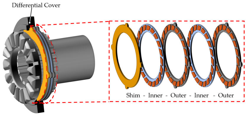
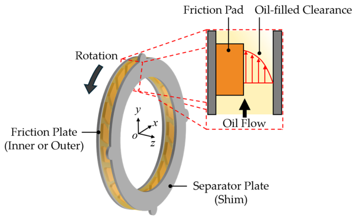
Driven by greenhouse gas emission regulations and the growth of the electric vehicle (EV) market, automotive powertrains are rapidly transitioning from internal combustion engine-based systems to electrified powertrain architectures. In electrified drivetrains, stable torque delivery, high drivetrain efficiency, and compact packaging are key design requirements [1,2]. A mechanical limited-slip differential (mLSD) improves handling and driving stability by controlling torque transmission between the driving wheels [3], whereas a disconnector reduces unnecessary power transmission and rotational losses by disconnecting the drive shaft from the power transmission path under specific operating conditions [4]. To satisfy these functional and packaging requirements, an mLSD-integrated disconnector can be used as a compact drivetrain module that combines limited-slip differential and power-disconnection functions, as shown in Figure 1. In this module, a wet multi-plate clutch is used as a key component for power connection and disconnection. However, even in the disengaged state, a thin oil film remains in the clearance between the friction plate and the separator plate, as shown in Figure 2. The relative rotation between the plates shears this oil film and generates drag torque leading to residual torque transmission and mechanical power loss in the drivetrain [5,6,7,8,9,10]. Therefore, reducing drag torque in the disengaged wet clutch is important for improving the efficiency of the mLSD-integrated disconnector.
To reduce drag torque in wet clutch systems, previous studies have investigated the effects of operating conditions, lubricant flow behavior, groove geometry, and optimization-based design approaches [5,6,7,8,9,10,11,12,13,14,15,16,17,18]. These studies have shown that drag torque, particularly under open or disengaged clutch conditions, is strongly affected by rotational speed, plate clearance, oil viscosity, oil supply conditions, and the flow regime within the clutch clearance [6,7,8,9,11,12,13,14,15,16]. In addition, groove geometry plays an important role in modifying the lubricant flow path, pressure distribution, and wall shear stress, all of which directly influence drag torque [5,10,13,15,16,17,18]. Based on this relationship, recent studies have applied optimization-based design approaches to the design of groove geometry to further reduce drag torque in wet clutch systems [17,18]. However, most previous studies have focused on conventional wet clutch systems or specific groove profiles, and the application of groove geometry optimization to wet clutches used in mLSD-integrated disconnectors has remained limited. Moreover, in practical clutch design, reducing drag torque by simply enlarging the groove can decrease the effective friction pad area, which is closely related to the torque transmission capability in the engaged state. Previous studies on grooved wet-clutch friction surfaces have shown that groove area, groove depth, and groove pattern affect engagement characteristics, contact pressure, thermal behavior, and friction material wear [19,20]. Li et al. [20] examined groove area ratios ranging from approximately 10% to 25% and showed that an increase in groove area can reduce the effective land area and alter the contact pressure, engagement time, and wear characteristics. Based on these findings, the decrease in friction pad area relative to the reference geometry was conservatively restricted to within 2.5% in the present optimization. However, friction pad area alone does not fully represent engagement performance, which is also affected by contact pressure distribution, thermal behavior, friction characteristics, and wear. Accordingly, friction pad area was used as a first-order proxy for preserving engagement capability rather than as a direct measure of engagement performance.
In this study, the effects of friction pad and groove geometry on drag torque reduction in the disengaged wet clutch of an mLSD-integrated disconnector were numerically investigated under oil-filled single-phase conditions. This condition was selected because drag torque under open or disengaged clutch conditions is mainly governed by viscous shear when the clutch clearance remains filled with lubricant, making it suitable for evaluating geometry-induced changes in wall shear stress [11,15,16]. A three-dimensional CFD model was developed using ANSYS Fluent 2021 R1 while considering the porous characteristics of the friction pad [21,22]. A periodic sector including a single friction pad and groove was also modeled to represent the repeated pad arrangement. The numerical model was validated through comparison with the reference results of Razzaque and Kato [5]. Using the validated model, lubricant flow through the groove was analyzed to examine how friction pad and groove geometry affect oil discharge behavior, wall shear stress, and drag torque. Four geometry parameters, θ1, θ2, θ3, and w, were selected as design variables. To evaluate the independent effect of each geometry parameter, one parameter was varied at a time while the other parameters were fixed at their reference values, with the change in friction pad area limited to within 2.5% for each case. Based on the parametric CFD results, full factorial combination analysis and PCHIP methods were applied to derive an optimized geometry that minimizes drag torque while considering the effective friction pad area [23,24]. The results provide a practical groove design approach for reducing drag torque while preserving the friction pad area.

2. Numerical Model and Optimization Methods

2.1. Numerical Model

In this study, a three-dimensional numerical model was developed using ANSYS Fluent 2021 R1 to analyze drag torque under fully oil-filled, single-phase conditions, where viscous shear in the lubricant film is the dominant drag torque mechanism. The present analysis was limited to steady, incompressible, laminar flow at a separator plate rotational speed of 1000 rpm. The continuity and momentum equations for the free-flow clutch clearance and the porous friction pad are given by Equations (1)–(4).
· u = 0
ρ u · u = p + μ 2 u
· u D = 0
ρ u D · u D = p + μ e f f 2 u μ K u D , where   μ e f f = μ 1 ε 2.5 ,   u D = ε u
where K, p, u, uD, ε, μ, μeff, and ρ are the permeability of the porous friction pad, pressure, velocity vector in the free-flow clutch clearance, Darcy velocity vector in the porous friction pad, porosity, dynamic viscosity, effective dynamic viscosity, and oil density, respectively. The paper-based friction pad was treated as a porous medium to account for the flow resistance within the friction material. Accordingly, the free-flow clutch clearance was governed by the standard incompressible momentum equation, as given in Equation (2), whereas the porous friction pad was governed by the Darcy–Brinkman-type momentum equation, as given in Equation (4). The porosity and permeability of the paper-based friction pad were set to 0.55 and 5.0 × 10⁻¹³ m2, respectively, based on representative values reported in previous studies [21,22].
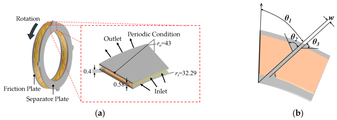
As shown in Figure 3, the computational domain was defined as a single clearance between one friction plate and one separator plate, including one friction pad and the adjacent groove. This local domain was modeled instead of the entire multi-plate clutch pack to focus on the oil shear flow contributing to drag torque. Because the friction pad geometry is periodically repeated in the circumferential direction, a 1/20 sector of the clutch was used to represent the repeated pad arrangement. Periodic boundary conditions were applied to both circumferential sides of the sector. The friction plate wall was set as stationary, whereas the separator plate wall was assigned a rotational speed of 1000 rpm to reproduce the relative motion in the disengaged state. A no-slip condition was applied to all solid walls. Pressure boundary conditions were applied to represent the oil supply and discharge conditions. The inner radial boundary was defined as a pressure inlet with a total gauge pressure of 4740.73 Pa, while the outer radial boundary was defined as a pressure outlet with a gauge pressure of 0 Pa. The working fluid density and dynamic viscosity were set to ρ = 829.5 kg/m3 and μ = 0.01832 Pa·s, respectively. The convergence criterion was set to a residual of 1.0 × 10⁻⁶.
The groove geometry of the friction pad was parameterized using three angle variables (θ1, θ2, θ3) and the groove width (w), as shown in Figure 3b. θ1 represents the groove angle, whereas θ2 and θ3 define the outlet side groove geometry. These parameters were analyzed to determine how friction pad and groove geometry parameters affect oil discharge paths, shear stress distribution, and drag torque characteristics. The reference geometry was defined based on representative grooved wet-clutch friction plate configurations reported in previous drag-torque studies [15,25,26]. The reference geometry is set to θ1 = 38°, θ2 = 58°, θ3 = 30.8°, and w = 1.0 mm. All drag torque reduction rates and friction pad area reduction rates were calculated relative to this reference geometry.
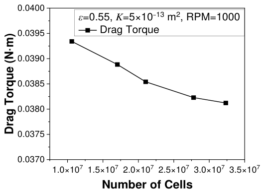
A mesh independence test was conducted using five mesh systems containing approximately 1.1 × 10⁷, 1.7 × 10⁷, 2.1 × 10⁷, 2.8 × 10⁷, and 3.2 × 10⁷ cells. Figure 4 shows the variation in the calculated drag torque with mesh refinement. The drag torque decreased progressively as the number of cells increased, and the difference between the coarsest and finest meshes was approximately 3.2%. In particular, the difference between the 2.8 × 10⁷ cell and 3.2 × 10⁷ cell meshes was only 0.28%, indicating that further mesh refinement had a negligible effect on the calculated drag torque. Therefore, the 3.2 × 10⁷ cell mesh was selected for the subsequent simulations.

2.2. Drag Torque and Friction Pad Area Evaluation

The drag torque is evaluated from the circumferential wall shear stress acting on the separator plate surface. The circumferential component was obtained from the Cartesian wall shear stress components using Equation (5).
τ θ = τ x sin θ + τ y cos θ
where τx, τy, τθ, and θ are the wall shear stress component in the x-direction, the wall shear stress component in the y-direction, the circumferential wall shear stress, and the circumferential coordinate, respectively. To quantify the overall circumferential wall shear stress acting on the separator plate, the area-averaged value is defined as
τ θ = 1 A s A s τ θ d A
where As and ⟨τθ⟩ are the separator plate surface area and the area-averaged circumferential wall shear stress, respectively. The drag torque is then calculated by integrating the circumferential wall shear stress over the separator plate surface using Equation (7).
T = A s τ θ r d A
where r and T are the radial position and the drag torque, respectively. Because a 1/20 periodic sector was used in the numerical model, the torque calculated in the sector was converted to the full clutch geometry by considering the number of repeated sectors.
To evaluate the influence of groove geometry, the relative changes in friction pad area, drag torque, and area-averaged circumferential wall shear stress are defined with respect to the reference geometry using Equations (8)–(10), respectively.
R A = A A r e f A r e f × 100   %
R T = T T r e f T r e f × 100   %
R τ θ = τ θ τ θ r e f τ θ r e f × 100   %
where A, Aref, RA, RT, Rτθ, Tref, and ⟨τθref are the friction pad area of each groove geometry, friction pad area of reference geometry, relative change in friction pad area, relative change in drag torque, relative change in area-averaged circumferential wall shear stress, drag torque of the reference geometry, and area-averaged circumferential wall shear stress of the reference geometry, respectively.

2.3. Friction Pad Geometry Optimization

The effects of the groove design parameters were analyzed by varying θ1, θ2, θ3, and w. To evaluate the individual influence of each parameter, one parameter was varied while the other parameters were fixed at the reference values. The design variable vector and the range of each design variable are defined by Equations (11) and (12).
x = θ 1 , θ 2 , θ 3 , w
0 θ 1 60 ,   18 θ 2 98 ,   0 θ 3 60 ,   0.8 w 1.2
where x is the design variable vector. These ranges define the overall design space used for parametric analysis and geometry optimization. For each design case, the relative changes in friction pad area and drag torque were calculated using Equations (8) and (9). These relative changes were used to quantify the individual effect of each design variable.
To derive the optimum groove geometry without performing CFD simulations for every combined geometry, two optimization approaches, namely a full factorial combination analysis and a PCHIP-based interpolation approach, were applied based on the individual parameter effects. In both approaches, the response of a combined groove geometry was estimated using an independent effect superposition approach. The predicted relative changes in friction pad area and drag torque were calculated by summing the individual effects, as expressed in Equations (13) and (14).
R ^ A x = i = 1 4 R A , i x i
R ^ T x = i = 1 4 R T , i x i
where i, R ^ A , R ^ T , RA,i, RT,i, and xi are the design variable index, the predicted relative changes in friction pad area and drag torque for the combined groove geometry, the individual effect of the i-th design variable on the friction pad area and the drag torque, and the i-th design variable, respectively. The groove geometry was selected to reduce drag torque while limiting the decrease in friction pad area to within 2.5%. The independent effect superposition approach assumes that the effects of θ1, θ2, θ3, and w are additive. Therefore, interaction effects among the groove parameters are not explicitly represented in the present optimization framework. Accordingly, the predicted responses of the combined geometries should be interpreted as engineering approximations based on the independently evaluated parameter effects.
A full factorial combination analysis was performed using the independent effect superposition approach based on the single-parameter CFD results, rather than by performing direct CFD simulations for every combination. The number of evaluated combinations is expressed as
N = i = 1 4 n i
where N and ni are the total number of evaluated combinations and the number of predefined levels for the i-th design variable, respectively. The full factorial combination analysis was used to identify the best geometry among the discrete candidate combinations.
The PCHIP method was then applied to estimate intermediate geometries between the predefined design levels. In this approach, interpolation functions were constructed for the individual effects obtained from the single-parameter CFD results. Therefore, geometries that were not directly simulated could be evaluated within the same superposition framework. The PCHIP interpolation function, expressed using cubic Hermite basis functions, and normalized coordinate are given by Equation (16) and Equation (17), respectively.
y x = h 00 t y k + h 10 t x k + 1 x k m k + h 01 t y k + 1 + h 11 t x k + 1 x k m k + 1
t = x x k x k + 1 x k
where mk, mk+1, t, x, xk, xk+1, y, yk, and yk+1 are the slopes at xk and xk+1, normalized coordinate, interpolation point, lower and upper bounds of the interpolation interval, interpolated value, and function values at xk and xk+1, respectively. In this study, y represents either the individual effect on the friction pad area or the individual effect on the drag torque. For each design variable, the CFD-derived values of RA,i and RT,i at the predefined parameter levels were used as the interpolation nodes (xk, yk). Separate PCHIP functions were constructed for the friction pad area and drag torque responses of θ1, θ2, θ3, and w. Within each interpolation interval, each response was evaluated using the cubic polynomial defined by Equations (16)–(21). The predicted responses of a combined geometry were then obtained by substituting the interpolated individual effects into Equations (13) and (14). The Hermite basis functions in Equation (16) are given by
h 00 t = 2 t 3 3 t 2 + 1
h 10 t = t 3 2 t 2 + t
h 01 t = 2 t 3 + 3 t 2
h 11 t = t 3 t 2
For the full factorial combination analysis, an exhaustive enumeration procedure was used. All discrete combinations of the predefined design-variable levels were generated, and their combined responses were estimated using Equations (13) and (14). Combinations exceeding the 2.5% friction pad area reduction constraint were excluded, and the feasible combination with the largest predicted drag torque reduction was selected. For the PCHIP-based optimization, separate interpolation functions were constructed for the area and drag torque responses of each design variable using Equations (16)–(21). The interpolated functions were evaluated over the prescribed design-variable ranges using a grid-search procedure. The feasible point with the largest predicted drag torque reduction was selected as the PCHIP-based optimum.

3. Results and Discussion

3.1. Numerical Model Validation

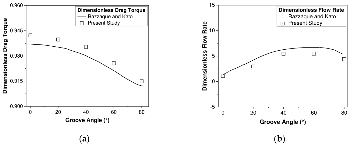
To validate the present numerical model, Figure 5 compares the dimensionless drag torque and dimensionless flow rate obtained from the present simulation with the numerical results of Razzaque and Kato [5]. The validation model was constructed using the same geometric and operating conditions as those used in the reference study. As shown in Figure 5, the present numerical results showed good agreement with the reference results [5]. The average deviation of the dimensionless drag torque was less than 0.5%. The dimensionless flow rate showed a trend similar to that of the reference result. These results indicate that the present numerical model can reasonably reproduce the dimensionless drag torque and flow rate characteristics obtained by Razzaque and Kato [5] under the same geometric and operating conditions. However, this comparison represents numerical validation and does not constitute experimental validation of the specific mLSD-integrated disconnector clutch geometry investigated in this study.

3.2. Effect of Groove Geometry on Shear Stress and Drag Torque

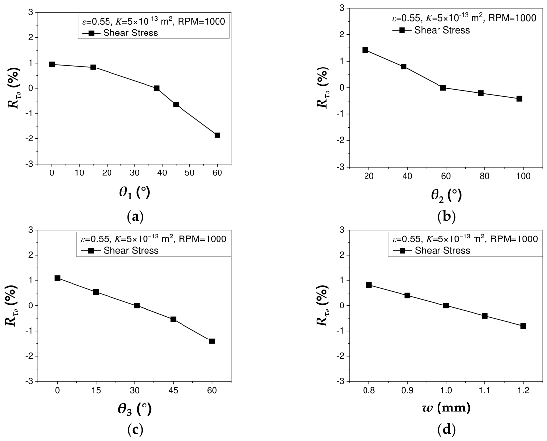
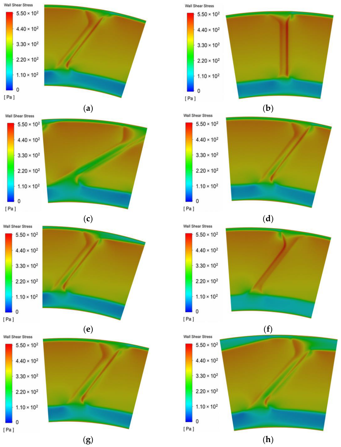
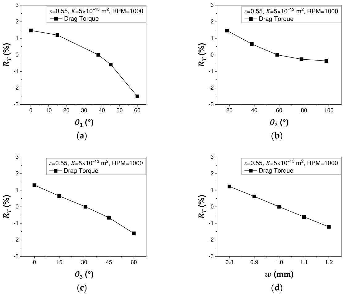
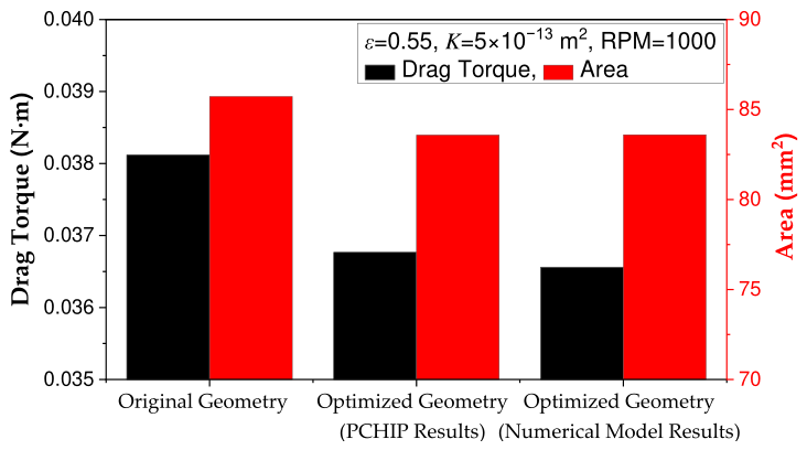
The effects of the groove design parameters on the area-averaged circumferential wall shear stress (⟨τθ⟩), corresponding local distribution, and drag torque are shown in Figure 6, Figure 7 and Figure 8, respectively. Figure 6 quantifies the overall change in ⟨τθ⟩, whereas Figure 7 identifies the regions where the local stress changed. Figure 8 presents the resulting change in drag torque. The groove angles (θ1, θ2, and θ3) and the groove width (w) were varied independently. For the reference geometry, ⟨τθ⟩ and drag torque were 402.89 Pa and 0.0381 N·m, respectively. To facilitate comparison among the groove geometries, both quantities were expressed as relative changes with respect to these reference values. Because drag torque is calculated as a radius-weighted surface integral of τθ, Figure 8 reflects both the magnitude and radial distribution of the wall shear stress presented in Figure 6 and Figure 7.
As shown in Figure 6a, ⟨τθ⟩ decreased as θ1 increased. Among the investigated parameter ranges, θ1 produced the largest decrease. The corresponding distributions in Figure 7a–c show that the high-wall-shear-stress region on the separator plate surface was strongly affected by θ1. Compared with the reference geometry, θ1 = 0° case exhibited a broader region of relatively high stress, whereas the θ1 = 60° case showed a lower area-averaged value. This change is consistent with the formation of a more favorable radially outward oil discharge path. Figure 6b shows that the effect of θ2 on ⟨τθ⟩ was relatively limited compared with those of the other design parameters. Although θ2 changed the outlet-side groove geometry, it was located opposite to the main radially outward oil flow. Therefore, θ2 did not strongly modify the main oil discharge path, and its contribution to reducing wall shear stress was smaller than those of θ1, θ3, and w. As shown in Figure 6c, increasing θ3 also reduced ⟨τθ⟩. The distributions in Figure 7a,d,e show that the region of high circumferential wall shear stress near the outer radial boundary decreased as θ3 increased. This change was primarily observed near the groove outlet, indicating that θ3 modified the outlet-side oil flow. The reduction in the high-stress region consequently decreased ⟨τθ⟩. Figure 6d shows that ⟨τθ⟩ decreased monotonically as w increased from 0.8 to 1.2 mm. Increasing w enlarged the oil discharge passage, allowing lubricant to exit the clutch clearance more readily. Consequently, the region of high circumferential wall shear stress decreased, as shown in Figure 7a,f,g. However, unlike the groove angles, the groove width directly changes the effective friction pad area. Therefore, the effect of w should be interpreted together with the drag torque variation and the area constraint.
Figure 8 presents the drag torque variation caused by each groove design parameter. As θ1 increased from 0° to 60°, drag torque decreased by approximately 3.96%, as shown in Figure 8a. The corresponding reductions for θ2, θ3, and w were approximately 1.18%, 2.87%, and 2.41% over their respective ranges, as presented in Figure 8b–d. Among the design parameters, θ1 produced the largest drag torque reduction, whereas θ2 had the smallest effect. The drag torque trends generally followed the changes in ⟨τθ⟩. Differences in their reduction rates resulted from the radial distribution of τθ, which is considered in the drag torque calculation.
Overall, these results indicate that drag torque can be reduced not simply by increasing the groove area, but by forming an effective oil discharge path through appropriate control of the inlet- and outlet-side groove geometries. The results also show that drag torque reduction is closely related to the decrease in wall shear stress and the reduction in the high-wall-shear-stress region. However, because drag torque is an area-integrated quantity, it should be evaluated by considering both the wall shear stress distribution and the effective friction pad area.

3.3. Groove Geometry Optimization

Based on the results in Section 3.2, groove geometry optimization was performed to reduce the drag torque of the wet clutch in the disengaged state while limiting the reduction in friction pad area to 2.5%. Using the individual effects of θ1, θ2, θ3, and w, the response of each combined groove geometry was estimated based on the independent effect superposition approach described in Section 2.3. The full factorial combination analysis was used as a discrete-level optimization baseline, whereas the PCHIP-based interpolation approach was used to evaluate intermediate geometries between the predefined design levels.
Figure 9 compares the optimization results obtained using the full factorial combination analysis and PCHIP-based interpolation approaches. In the full factorial combination analysis, the geometry with θ1 = 60°, θ2 = 98°, θ3 = 60°, and w = 0.800 mm showed the largest predicted drag torque reduction among the discrete candidate combinations. The predicted decreases in drag torque and friction pad area relative to the reference geometry were 3.28% and 2.37%, respectively. In the PCHIP-based interpolation approach, the geometry with θ1 = 60°, θ2 = 59.60°, θ3 = 50.55°, and w = 1.003 mm showed the largest drag torque reduction. The predicted decreases in drag torque and friction pad area relative to the reference geometry were 3.56% and 2.50%, respectively. Because this geometry provided a larger drag torque decrease than the full factorial combination analysis result while satisfying the area constraint, it was selected as the final groove geometry.
The selected geometry was then evaluated using the established CFD model. The final CFD-evaluated geometry had a friction pad area of 83.59 mm2, corresponding to a reduction of 2.49% relative to the reference geometry. Therefore, the final geometry satisfied the prescribed 2.5% friction pad area constraint. The direct CFD evaluation showed a 4.10% reduction in drag torque, compared with the PCHIP-predicted reduction of 3.56%. The difference between the two reduction rates was 0.54 percentage points. The relative difference between the PCHIP-predicted and CFD-evaluated drag torque values was 0.56%, calculated relative to the direct CFD result. These results support the drag torque reduction achieved by the selected geometry under the conditions investigated. However, interaction effects among the design parameters were not separately quantified. Figure 7h shows the wall shear stress distribution of the CFD-evaluated optimized geometry. Compared with the reference geometry in Figure 7a, the optimized geometry exhibited a reduced high-wall-shear-stress region on the separator plate surface, which is consistent with the reduction in drag torque. This reduction was mainly attributed to improved radially outward oil flow through the groove and the resulting decrease in wall shear stress. At θ1 = 60°, the groove guided the oil inflow in a direction favorable for radially outward discharge. The combination of θ2 = 59.60° and θ3 = 50.55° improved the outlet discharge path, while w = 1.003 mm provided a sufficient flow passage for oil discharge under the area constraint. Finally, the PCHIP-based geometry selection showed that drag torque can be reduced not simply by decreasing the friction pad area, but by forming an effective oil discharge path and reducing wall shear stress.
The present results are limited to the fully oil-filled, single-phase, steady, laminar flow condition investigated at 1000 rpm. Under partially filled or high-speed operating conditions, free-surface deformation, aeration, and multiphase flow may alter the oil distribution and drag torque characteristics. In addition, variations in oil supply rate, rotational speed, temperature-dependent viscosity, and clutch clearance may change the relative effects of the groove design parameters. Therefore, the quantitative results and the optimized geometry obtained in this study should not be directly generalized beyond the investigated operating condition.

4. Conclusions

In this study, the effects of friction pad groove geometry on drag torque in the disengaged state of a wet clutch with a paper-based friction pad were numerically analyzed under oil-filled single-phase conditions. A three-dimensional CFD model was developed using ANSYS Fluent 2021 R1. The paper-based friction pad was modeled as a porous medium to account for the flow resistance within the friction material. The numerical model was validated by comparison with dimensionless drag torque and flow rate results of Razzaque and Kato [5]. The calculated dimensionless drag torque showed good agreement with the reference result, with an average deviation of less than 0.5%. The dimensionless flow rate also showed a similar trend to the reference result. These results indicate that the present model can reasonably predict the shear-driven lubricant flow and drag torque characteristics of a disengaged wet clutch.
The effects of the groove design parameters θ1, θ2, θ3, and w were evaluated using the area-averaged circumferential wall shear stress (⟨τθ⟩), local wall shear stress distribution, and drag torque. Under the present operating conditions and within the investigated parameter ranges, increasing these parameters generally reduced ⟨τθ⟩ by modifying the oil discharge path. Among the design parameters, θ1 produced the largest drag torque reduction because it promoted radially outward oil discharge and reduced the region of high-τθ on the separator plate surface. In contrast, θ2 had the smallest effect because it did not substantially alter the main oil discharge path. Increasing θ3 reduced the high-shear-stress region near the outer radial boundary adjacent to the groove outlet. Increasing w enlarged the oil discharge passage, resulting in lower ⟨τθ⟩ and drag torque. Over the investigated ranges, drag torque decreased by approximately 3.96%, 1.18%, 2.87%, and 2.41% as θ1, θ2, θ3, and w increased, respectively. These results indicate that drag torque reduction depends on both the overall magnitude and radial distribution of τθ.
Based on the parametric CFD results, full factorial combination analysis and PCHIP-based interpolation approaches were applied to optimize the groove geometry while limiting the decrease in friction pad area to within 2.5%. The full factorial combination analysis approach was used as a discrete-level optimization baseline. The predicted decreases in drag torque and friction pad area relative to the reference geometry were 3.28% and 2.37%, respectively. The PCHIP-based interpolation approach was then used to evaluate intermediate geometries between the predefined design levels. The selected PCHIP-based geometry showed predicted decreases in drag torque and friction pad area of 3.56% and 2.50%, respectively. This geometry was selected as the final groove geometry because it provided a larger drag torque decrease than the full factorial combination analysis result while satisfying the area constraint. The selected geometry was further evaluated using the CFD model. The CFD result showed a 4.10% decrease in drag torque relative to the reference geometry. The relative difference between the PCHIP-predicted and CFD-evaluated drag torque values was 0.56%, calculated relative to the direct CFD result. These results show that drag torque can be reduced not simply by increasing the groove area, but by forming an effective oil discharge path that decreases wall shear stress in the clutch clearance. Therefore, the CFD-based parametric optimization procedure used in this study can provide a practical design approach for reducing drag torque in wet clutch systems with consideration of both shear stress reduction and friction pad area preservation.

Author Contributions

Conceptualization, S.P.J.; methodology, S.P.J.; software, S.J.P.; validation, S.J.P.; investigation, S.J.P.; data curation, S.J.P., G.B., H.K.J., H.J.L.; writing—original draft preparation, S.J.P.; writing—review and editing, S.P.J.; project administration, S.P.J.; funding acquisition, S.P.J. All authors have read and agreed to the published version of the manuscript.

Funding

This work was supported by Korea Planning & Evaluation Institute of Industrial Technology (KEIT) grant funded by Korean government (MOTIE) (RS-2024-00469455).

Institutional Review Board Statement

Not applicable.

Informed Consent Statement

Not applicable.

Data Availability Statement

The original contributions presented in this study are included in the article. Further inquiries can be directed to the corresponding author.

Conflicts of Interest

The authors declare no conflicts of interest.

Abbreviations

Afriction pad area of each groove geometry [mm2]
Areffriction pad area of the reference geometry [mm2]
Asseparator plate surface area [mm2]
idesign variable index
Kpermeability of the porous friction pad [m2]
mkslope at xk
mk+1slope at xk+1
Ntotal number of evaluated combinations
ninumber of predefined levels for the i-th design variable
ppressure [Pa]
rradial position [m]
R ^ A relative change in friction pad area [%]
RA,iindividual effect of the i-th design variable on the friction pad area [%]
R ^ T relative change in drag torque [%]
RT,iindividual effect of the i-th design variable on the drag torque [%]
R τ θ relative change in wall shear stress [%]
tnormalized coordinate
Tdrag torque [N·m]
Trefdrag torque of the reference geometry [N·m]
uvelocity vector [m/s]
uDDarcy velocity vector [m/s]
wgroove width [mm]
xdesign variable vector or interpolation point
xii-th design variable
xklower bound of the interpolation interval
xk+1upper bound of the interpolation interval
yinterpolated value
ykfunction value at xk
yk+1function value at xk+1
εporosity of the friction pad
θcircumferential coordinate [rad]
θ1groove angle [°]
θ2outlet side groove angle parameter [°]
θ3outlet side groove angle parameter [°]
μdynamic viscosity [Pa·s]
μeffeffective dynamic viscosity [Pa·s]
ρoil density [kg/m3]
τxwall shear stress component in the x-direction [Pa]
τywall shear stress component in the y-direction [Pa]
τθcircumferential wall shear stress [Pa]
τθarea-averaged circumferential wall shear stress [Pa]
τθrefarea-averaged circumferential wall shear stress of the reference geometry [Pa]

References

  1. Kwon, K.; Jo, J.; Min, S. Multi-objective gear ratio and shifting pattern optimization of multi-speed transmissions for electric vehicles considering variable transmission efficiency. Energy 2021, 236, 121419. [Google Scholar] [CrossRef]
  2. Kwon, K.; Lee, J.-H.; Lim, S.-K. Optimization of multi-speed transmission for electric vehicles based on electrical and mechanical efficiency analysis. Appl. Energy 2023, 342, 121203. [Google Scholar] [CrossRef]
  3. Russo, R.; Strano, S.; Terzo, M. Enhancement of vehicle dynamics via an innovative magnetorheological fluid limited slip differential. Mech. Syst. Signal Process. 2016, 70–71, 1193–1208. [Google Scholar] [CrossRef]
  4. Škugor, B.; Deur, J.; Chen, W.; Zhang, Y.; Dai, E. Optimization of straight-line driving torque vectoring for energy-efficient operation of electric vehicles with multiple motors and disconnect clutches. Optim. Eng. 2025, 26, 753–780. [Google Scholar] [CrossRef]
  5. Razzaque, M.M.; Kato, T. Effects of groove orientation on hydrodynamic behavior of wet clutch coolant films. J. Tribol. 1999, 121, 56–61. [Google Scholar] [CrossRef]
  6. Kitabayashi, H.; Li, C.; Hiraki, H. Analysis of the various factors affecting drag torque in multiple-plate wet clutches. In Proceedings of the 2003 JSAE/SAE International Spring Fuels and Lubricants Meeting, Yokohama, Japan, 19–22 May 2003; SAE Technical Paper 2003-01-1973; SAE International: Warrendale, PA, USA, 2003. [Google Scholar]
  7. Aphale, C.R.; Cho, J.; Schultz, W.W.; Ceccio, S.L.; Yoshioka, T.; Hiraki, H. Modeling and parametric study of torque in open clutch plates. J. Tribol. 2006, 128, 422–430. [Google Scholar]
  8. Yuan, Y.; Liu, E.A.; Hill, J.; Zou, Q. An improved hydrodynamic model for open wet transmission clutches. J. Fluids Eng. 2007, 129, 333–337. [Google Scholar]
  9. Hu, J.; Peng, Z.; Wei, C. Experimental research on drag torque for single-plate wet clutches. J. Tribol. 2012, 134, 014502. [Google Scholar] [CrossRef]
  10. Huang, J.; Fan, Y.; Qiu, M.; Fang, W. Effects of groove on behavior of flow between hydro-viscous drive plates. J. Cent. S. Univ. 2012, 19, 347–356. [Google Scholar] [CrossRef]
  11. Iqbal, S.; Al-Bender, F.; Pluymers, B.; Desmet, W. Mathematical model and experimental evaluation of drag torque in disengaged wet clutches. ISRN Tribol. 2013, 2013, 206539. [Google Scholar] [CrossRef]
  12. Zhou, X.; Walker, P.; Zhang, N.; Zhu, B.; Ruan, J. Numerical and experimental investigation of drag torque in a two-speed dual clutch transmission. Mech. Mach. Theory 2014, 79, 46–63. [Google Scholar] [CrossRef]
  13. Mahmud, S.F.; Pahlovy, S.A.; Kubota, M.; Ogawa, M.; Takakura, N. Multi-phase simulation for studying the effect of different groove profiles on the drag torque characteristics of transmission wet clutch. In Proceedings of the SAE 2016 World Congress and Exhibition, Detroit, MI, USA, 12–14 April 2016; SAE Technical Paper 2016-01-1144; SAE International: Warrendale, PA, USA, 2016. [Google Scholar]
  14. Pahlovy, S.A.; Mahmud, S.F.; Kubota, M.; Ogawa, M.; Takakura, N. Development of an analytical model for prediction of drag torque characteristics of disengaged wet clutches in high speed region. In Proceedings of the WCXTM 17: SAE World Congress Experience, Detroit, MI, USA, 4–6 April 2017; SAE Technical Paper 2017-01-1132; SAE International: Warrendale, PA, USA, 2017. [Google Scholar]
  15. Neupert, T.; Benke, E.; Bartel, D. Parameter study on the influence of a radial groove design on the drag torque of wet clutch discs in comparison with analytical models. Tribol. Int. 2018, 119, 809–821. [Google Scholar] [CrossRef]
  16. Neupert, T.; Bartel, D. High-resolution 3D CFD multiphase simulation of the flow and the drag torque of wet clutch discs considering free surfaces. Tribol. Int. 2019, 129, 283–296. [Google Scholar] [CrossRef]
  17. Zhang, L.; Zhang, Y.; Wei, C.; Yan, Y. Optimization design of oil groove shape on the surface of friction plate in high-speed wet clutch aimed at minimizing drag torque. J. Tribol. 2024, 146, 034601. [Google Scholar] [CrossRef]
  18. Rogkas, N.; Patsouras, D.; Lazaridis, C.; Zalimidis, P.; Rakopoulos, D.; Spitas, V. Optimal groove design for viscous drag reduction in wet clutch lubrication to enhance energy-efficiency in power transmissions. Energy 2026, 348, 140376. [Google Scholar] [CrossRef]
  19. Jang, J.Y.; Khonsari, M.M.; Maki, R. Three-dimensional thermohydrodynamic analysis of a wet clutch with consideration of grooved friction surfaces. J. Tribol. 2011, 133, 011703. [Google Scholar]
  20. Li, M.; Khonsari, M.M.; McCarthy, D.M.C.; Lundin, J. Parametric analysis of wear factors of a wet clutch friction material with different groove patterns. Proc. Inst. Mech. Eng. Part J J. Eng. Tribol. 2017, 231, 1056–1067. [Google Scholar] [CrossRef]
  21. Miura, T.; Sekine, N.; Azegami, T.; Murakami, Y.; Itonaga, K.; Hasegawa, H. Study on the dynamic property of a paper-based wet clutch. In Proceedings of the International Congress & Exposition, Detroit, MI, USA, 23–26 February 1998; SAE Technical Paper 981102; SAE International: Warrendale, PA, USA, 1998. [Google Scholar]
  22. Marklund, P. Permeability measurements of sintered and paper based friction materials for wet clutches and brakes. SAE Int. J. Fuels Lubr. 2010, 3, 857–864. [Google Scholar] [CrossRef]
  23. Fritsch, F.N.; Carlson, R.E. Monotone piecewise cubic interpolation. SIAM J. Numer. Anal. 1980, 17, 238–246. [Google Scholar] [CrossRef]
  24. Salviano, L.O.; Dezan, D.J.; Yanagihara, J.I. Optimization of winglet-type vortex generator positions and angles in plate-fin compact heat exchanger: Response surface methodology and direct optimization. Int. J. Heat Mass Transf. 2015, 82, 373–387. [Google Scholar] [CrossRef]
  25. Ryu, J.S.; Sung, I.-H. Effects of friction plate area and clearance on the drag torque in a wet clutch for an automatic transmission. J. Korean Soc. Tribol. Lubr. Eng. 2014, 30, 337–342. [Google Scholar] [CrossRef]
  26. Wang, C.; Ding, W.; Zheng, X.; Zhu, H.; Tian, Z.; Xie, F.; Gao, K. Simulation and experimental study on the influence of oil groove structure on the drag torque of the wet clutch. Ind. Lubr. Tribol. 2021, 73, 846–854. [Google Scholar] [CrossRef]
Figure 1. Schematic view of an mLSD with multi-plate clutch packs.
Applsci 16 07285 g001
Figure 2. Disengaged state of a wet clutch.
Applsci 16 07285 g002
Figure 3. Numerical model. (a) Computational domain and boundary conditions; (b) groove geometry of the friction pad.
Applsci 16 07285 g003
Figure 4. Mesh convergence of the calculated drag torque.
Applsci 16 07285 g004
Figure 5. Validation results compared with the numerical results of Razzaque and Kato [5]. (a) Comparison of dimensionless drag torque; (b) comparison of dimensionless flow rate.
Applsci 16 07285 g005
Figure 6. Effect of groove geometry on relative change in wall shear stress. (a) Effect of θ1 on shear stress; (b) effect of θ2 on shear stress; (c) effect of θ3 on shear stress; (d) effect of w on shear stress.
Applsci 16 07285 g006
Figure 7. Wall shear stress distributions for representative groove geometries. (a) Reference geometry; (b) θ1 = 0°; (c) θ1 = 60°; (d) θ3 = 0°; (e) θ3 = 60°; (f) w = 0.8 mm; (g) w = 1.2 mm; (h) CFD-evaluated optimized geometry.
Applsci 16 07285 g007
Figure 8. Effect of groove geometry on relative change in drag torque. (a) Effect of θ1 on drag torque; (b) effect of θ2 on drag torque; (c) effect of θ3 on drag torque; (d) effect of w on drag torque.
Applsci 16 07285 g008
Figure 9. Optimization results of groove geometry.
Applsci 16 07285 g009
Disclaimer/Publisher’s Note: The statements, opinions and data contained in all publications are solely those of the individual author(s) and contributor(s) and not of MDPI and/or the editor(s). MDPI and/or the editor(s) disclaim responsibility for any injury to people or property resulting from any ideas, methods, instructions or products referred to in the content.