2.1. Materials
The studied material comprised water-based spent drilling fluids generated during the drilling of technological wells for uranium production operations in southern Kazakhstan. The fluids were collected from operational circulation and settling systems after completion of their primary drilling function. Each composite sample contained an aqueous phase, clay minerals, finely dispersed drilled-rock particles, and residual additives used to control rheological and filtration properties [
16,
17]. The scope of the present work is deliberately restricted to water-based systems with the characteristics reported in
Table 1. Direct transfer of the operating window to oil-based, highly saline, or invert-emulsion fluids is not claimed because those media require separate experimental verification.
Before each experimental run, the bulk sample was homogenized until no visible stratification remained and was then divided into test portions without dilution. Samples were stored in sealed containers to minimize evaporation and compositional drift. The suspension temperature was measured immediately before and after treatment, and all comparative series were conducted at 22 ± 2 °C. Controlling this parameter was necessary because viscosity, polymer adsorption, and aggregate-formation kinetics are temperature dependent.
Before the experiments, the main physicochemical characteristics of the initial suspension were determined.
Table 1 presents the physicochemical characteristics of the tested spent water-based drilling fluids.
The parameters in
Table 1 were selected because they directly govern hydrodynamic transport and flocculation. The solids mass fraction and d
50 determine collision frequency, settling behavior, and the probability of aggregate breakage; density affects hydraulic loading and separation; pH influences polymer adsorption; and moisture content defines the recoverable liquid fraction. The reported ranges characterize the field-derived water-based samples investigated here rather than a universal specification for all spent drilling fluids [
18].
The combination of 30–40% solids, a broad d50 range, and a moderately alkaline pH explains the limited effectiveness of unaided gravitational settling. Within these bounds, the method is applicable to water-based clay suspensions of comparable composition. For fluids outside this range, preliminary jar tests should be conducted to determine the appropriate flocculant type, dosage, and hydrodynamic operating window before scale-up.
2.2. Experimental Setup and Hydrodynamic Disperser
The experiments were conducted on a laboratory–pilot recirculating unit built around a custom vertical pressure-driven cylindrical hydrodynamic disperser. The process train comprised a feed tank with pre-mixing, a flocculant dosing point, a centrifugal pump, a flow meter, inlet and outlet pressure gauges, the disperser, a conditioning and settling tank, a clarified-water outlet, and a sludge-collection zone. The custom active chamber contained 2–4 cascades of perforated disks and freely moving steel balls with diameters of 5–8 mm. The peripheral holes were inclined by 20–30°, the hole length-to-diameter ratio was 4–5, the pressure drop per cascade was 20–60 kPa, and the jet velocity through the holes was 0.8–1.5 m/s. The active chamber and wetted lines were fabricated from corrosion-resistant steel.
The pump established recirculation through the disperser, and the required velocity gradient was set by adjusting the suspension flow rate and the measured pressure drop. Downstream separation was performed in a quiescent settling vessel. After reagent–hydrodynamic activation, the suspension entered the vessel, flocculated solids settled under gravity, clarified supernatant was withdrawn from the upper outlet, and compacted sludge was removed from the lower collection zone; no rotating separator was used. The stated treatment time therefore denotes the total controlled recirculation period rather than the single-pass residence time inside the disperser.
For engineering specification and scale-up, the custom laboratory–pilot configuration was benchmarked against the commercially available DSh-100 ball-type drilling-fluid disperser manufactured by JSC Krasnodar Plant NEFTEMASH (Krasnodar, Russia). The manufacturer specifies a nominal throughput of 15 m3/h, a working inlet pressure of 0.6 MPa, overall dimensions of 590 × 515 × 375 mm, a mass of 49 kg, 9.8 mm steel balls, and operation in combination with a centrifugal slurry pump. These values define the closest verified industrial equipment specifications; they were not used to generate or calculate the experimental results obtained with the custom multicascade chamber.
The DSh-100 is an in-line flow-through unit, for which the manufacturer does not specify a nominal batch working volume or a unique feed-pump model. Accordingly, the reference pump duty was defined by the verified operating point of 15 m
3/h at 0.6 MPa. The corresponding hydraulic power is 2.50 kW; for an assumed combined pump–drive efficiency of 0.58–0.65, the required shaft power is 3.85–4.31 kW. A 5.5 kW centrifugal slurry pump equipped with a variable-frequency drive was therefore selected as a conservative design option for the modular scale-up configuration. This pump rating is an engineering selection and is not presented as a measured characteristic of the laboratory unit.
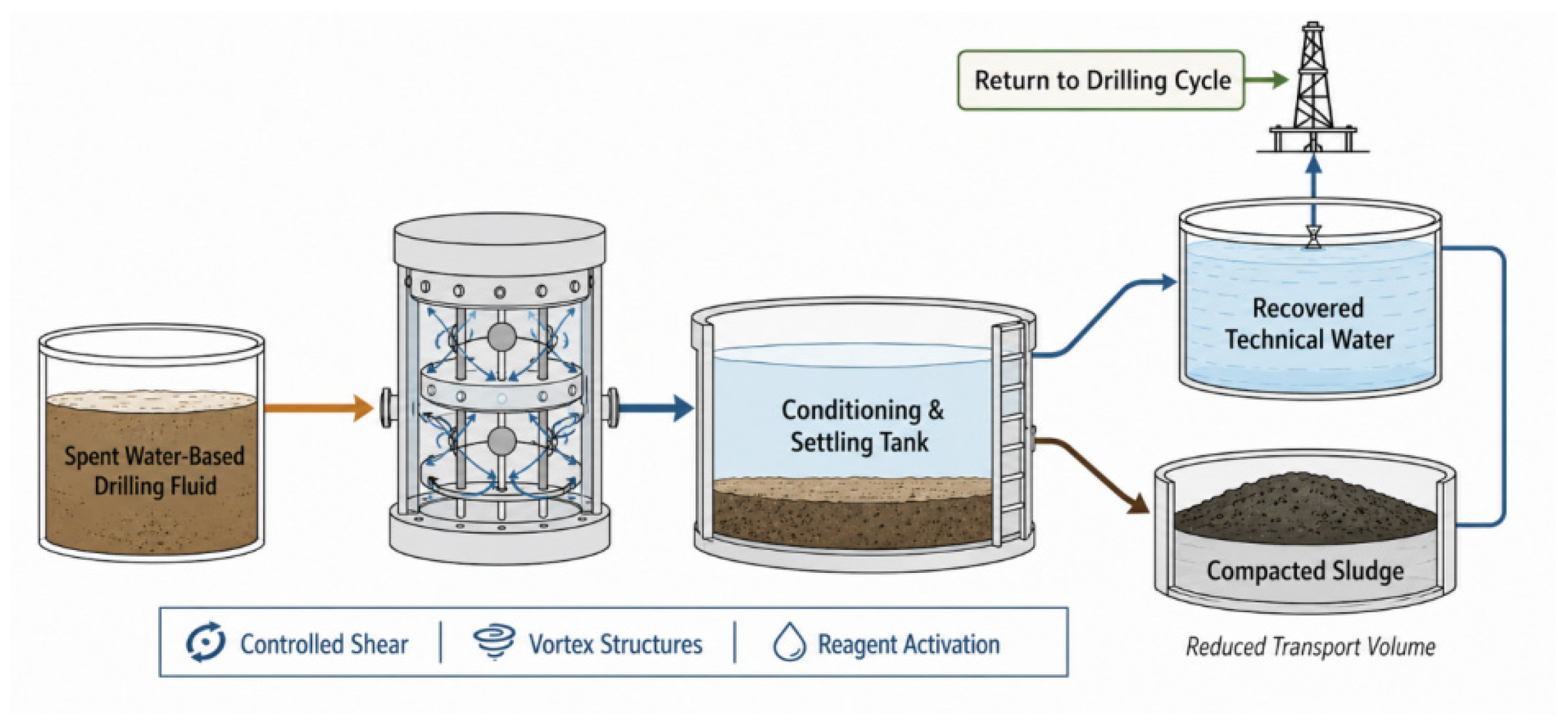
Figure 1 presents the process-level flowsheet used to define the material route from spent-fluid feed to recovered process water and compacted sludge.
As shown in
Figure 1, spent drilling fluid is first supplied to the hydrodynamic disperser, where controlled shear and vortex structures promote particle–reagent contact. The activated suspension then enters the conditioning and settling stage. The upper liquid fraction is collected for possible return to the drilling-water circuit, whereas the denser lower fraction is removed as compacted sludge. The figure therefore represents the overall resource loop, while
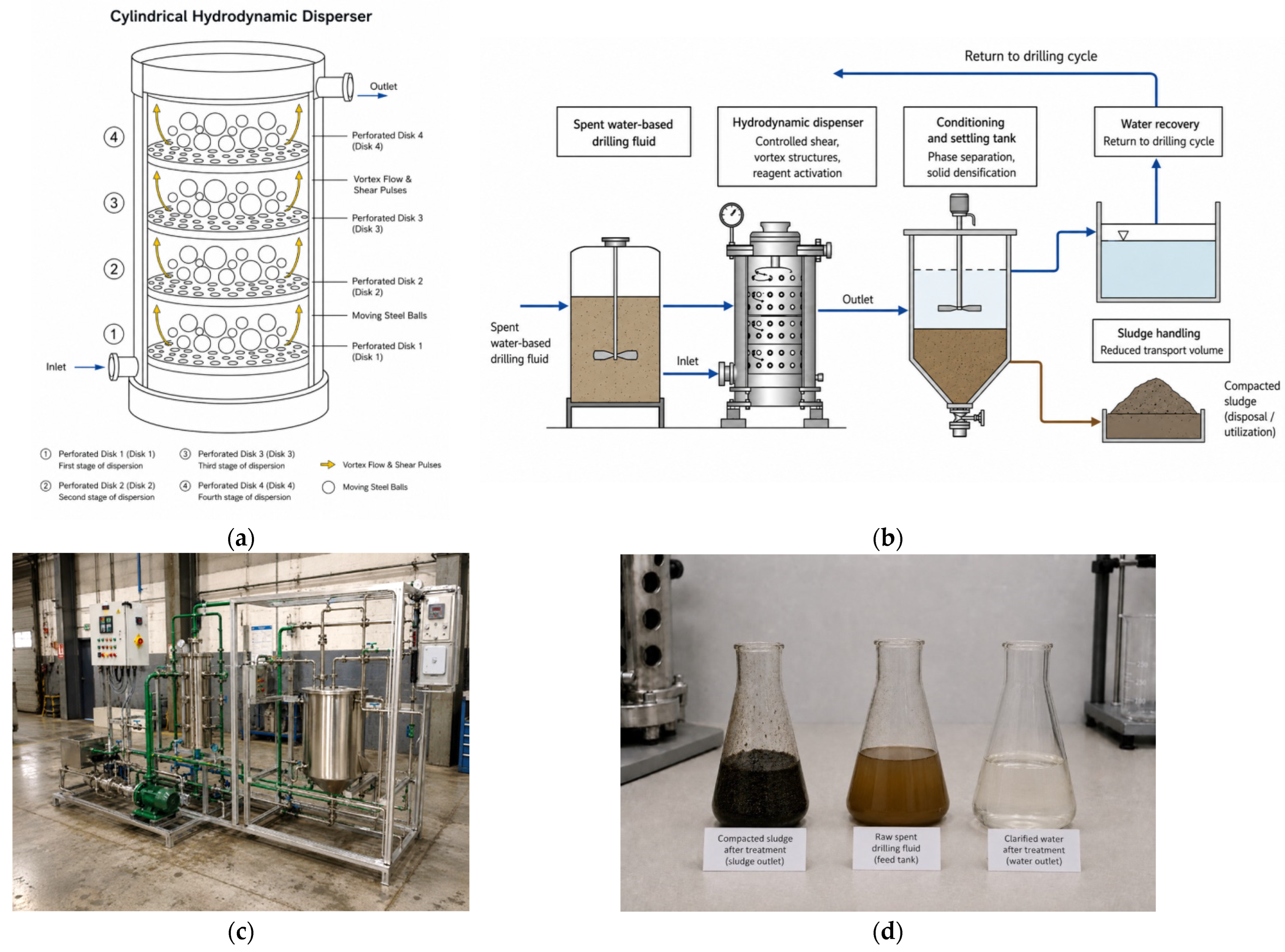
Figure 2 focuses on the apparatus structure and its integration into the experimental line [
19].
Figure 2 presents the apparatus-level engineering schematics: the internal arrangement of the cylindrical disperser and its position within the feed–treatment–settling sequence.
Figure 2 provides a composite engineering representation of the laboratory–pilot concept. It combines the process-line topology, the principal internal flow zones of the cylindrical hydrodynamic disperser, and illustrative phase states used to explain the expected transformation from the untreated suspension to clarified water and compacted sludge. Quantitative confirmation of this transformation is provided by the measured response variables reported in
Section 3. As shown in
Figure 2c, the proposed modular line comprises seven functional elements: a feed tank with pre-mixing, a metering pump for the Superfloc N-300 (NeftehimInnovation, Krasnoyarsk, Russia) working solution, a cylindrical hydrodynamic disperser, a gravity settling tank, a clarified-water outlet, a compacted-sludge outlet, and a recirculation pump. The hydraulic scheme defines the flow sequence, while the internal view explains the inlet acceleration, jet formation, expansion, vortex redistribution, and ball-assisted mixing zones.
Figure 2d illustrates the three process states used in the interpretation: initial suspension, recovered liquid phase, and compacted solid residue.
Key Design Parameters of the Disperser
Table 2 distinguishes the active-zone parameters used in the custom experimental disperser from the verified manufacturer data and calculated pump duty of the DSh-100 industrial scale-up reference.
The first block of
Table 2 defines the hydraulically active geometry used in the experiments. The second block provides a traceable industrial boundary for scale-up. The DSh-100 values are manufacturer data, whereas the 5.5 kW motor rating is a conservative engineering selection derived from the verified flow–pressure duty. This distinction prevents commercial reference specifications from being interpreted as unmeasured laboratory parameters.
2.3. Variables and Measured Parameters
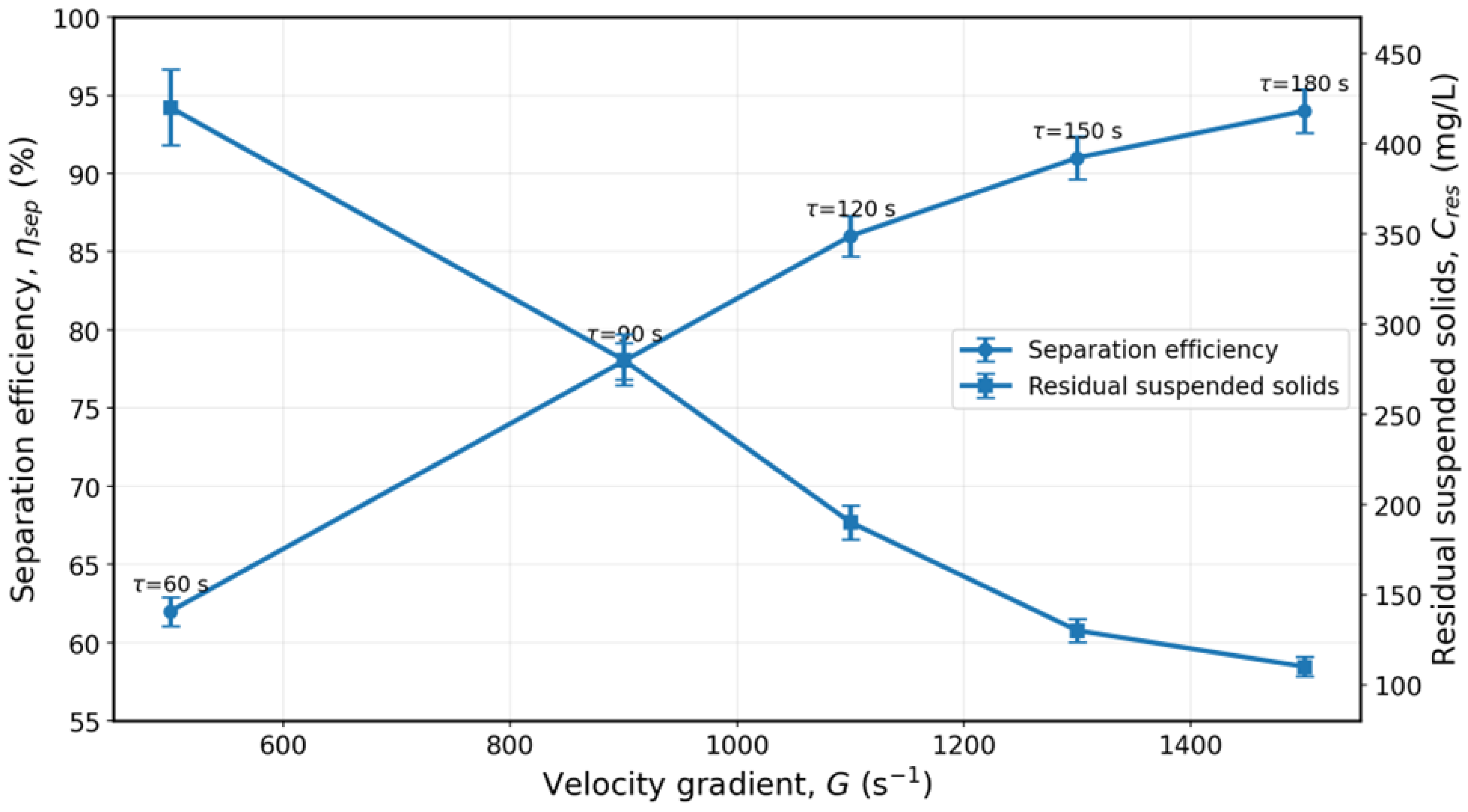
Three controlled factors were varied in the experiments: velocity gradient G = 500, 900, 1100, 1300, and 1500 s
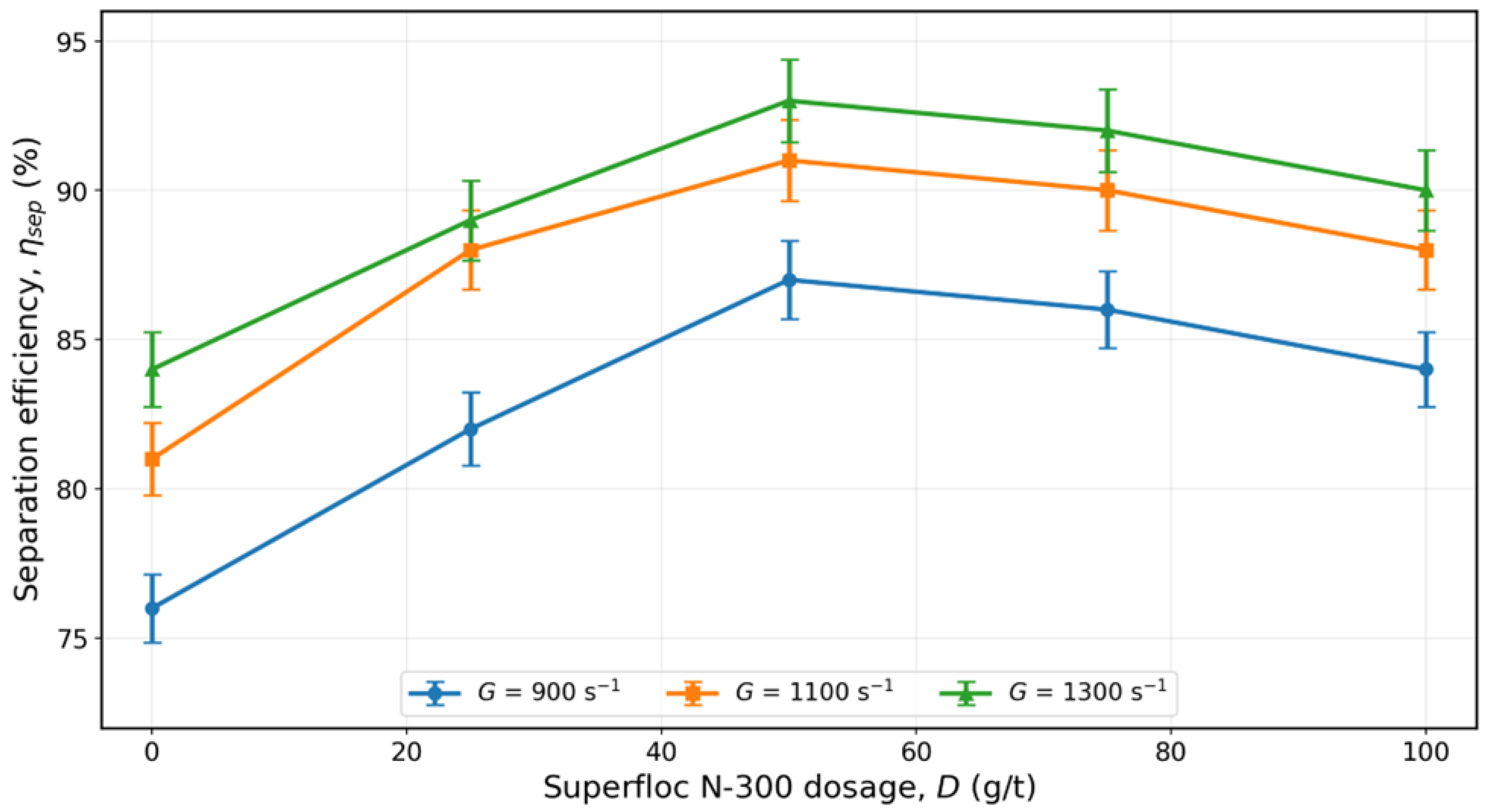
−1; treatment time τ = 60, 90, 120, 150, and 180 s; and flocculant dosage D = 0, 25, 50, 75, and 100 g/t. The reagent was Superfloc N-300, a commercial nonionic polyacrylamide flocculant supplied by Kemira and prepared as an aqueous working solution immediately before use. Separation efficiency η
sep, residual suspended-solids concentration C
res, sludge compactness ρ
s, process-water recovery R
w, sludge-volume reduction
Rs, and specific energy consumption
Esp were the measured response variables. The controlled factors and responses are summarized in
Table 3.
Table 3 defines the complete variable system used to evaluate the hydrodynamic treatment process. The controlled factors
G,
τ, and
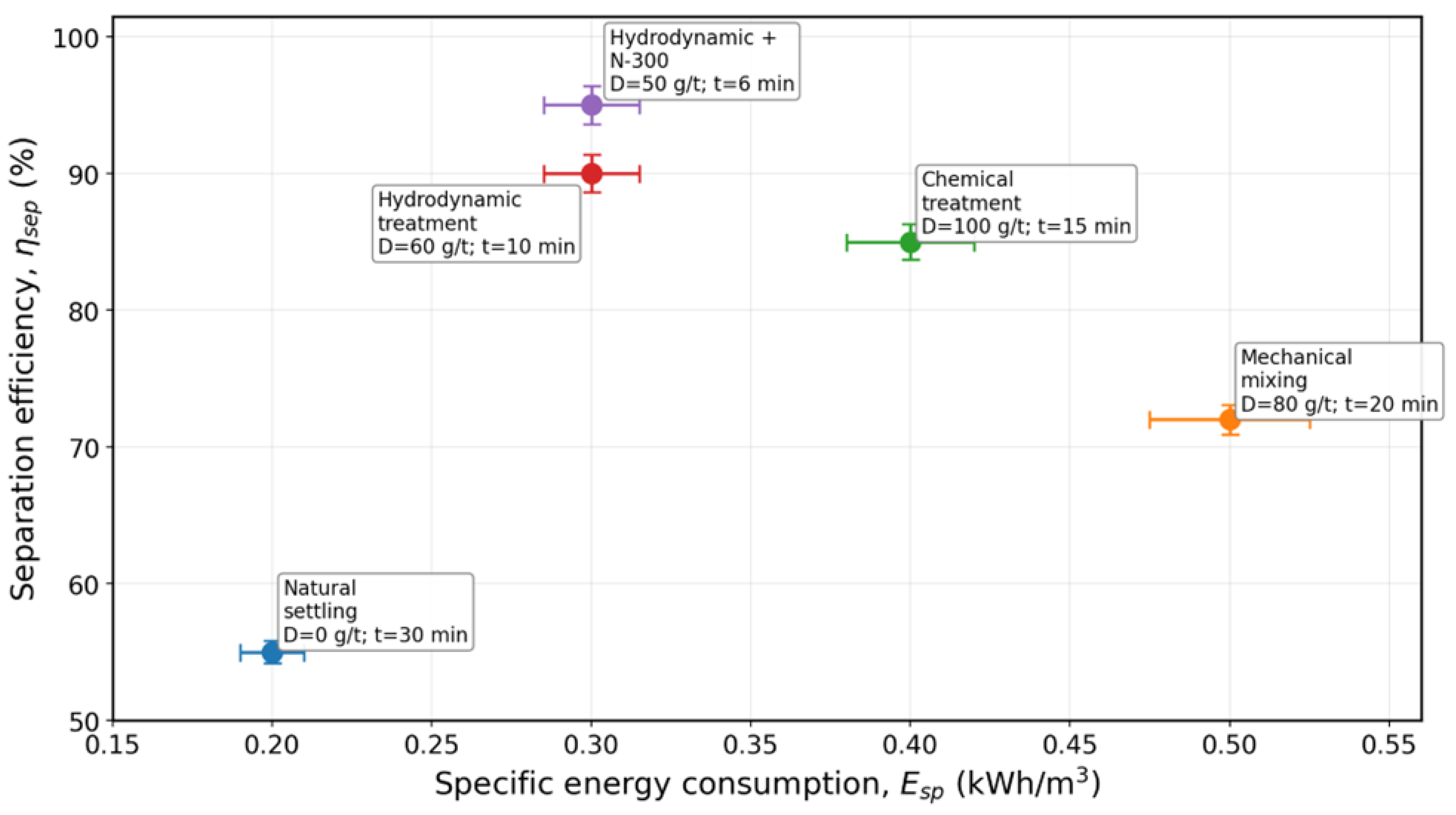
D characterize the intensity and duration of hydrodynamic action and the reagent input, whereas the response variables describe the resulting separation quality, residue properties, resource recovery, and energy demand. This structure allows the process to be assessed not only by separation efficiency, but also by the residual suspended-solids concentration, sludge compactness, process-water recovery, sludge-volume reduction, and specific energy consumption. Consequently, the operational optimum is determined as a multicriteria balance between treatment performance, reagent consumption, resource recovery, and energy efficiency rather than by maximizing a single response.
2.4. Analytical and Engineering Expressions
Separation efficiency was calculated using Equation (1):
where
is the initial suspended-solids concentration, mg/L, and
is the residual suspended-solids concentration after treatment and settling, mg/L.
Process-water recovery was calculated using Equation (2):
where
is the volume of the liquid phase returned, m
3;
is the initial volume of the treated suspension, m
3.
Sludge volume reduction is defined as
where
is the initial volume of the sludge phase, m
3;
is the volume of compacted residue after treatment, m
3.
Specific energy consumption was estimated as
where
is the working pressure drop, Pa;
is the volume flow, m
3/s;
t is the duration of treatment, s;
is the volume of the treated suspension, m
3;
is the efficiency of pumping equipment.
2.5. Experimental Workflow
The experimental procedure included three consecutive stages. First, the initial suspension was fed into the cylindrical hydrodynamic disperser, and the required hydrodynamic conditions were established by adjusting the pressure drop and the corresponding velocity gradient. At the second stage, flocculant N-300 was injected into the stream in a given dosage, after which the system was subjected to short-term reagent-hydrodynamic activation [
20]. Finally, the treated suspension was transferred to the settling unit. After settling, the quality of the separated liquid, the residual suspended-solids concentration, and the properties of the solid residue were evaluated [
21].
For each mode, the values of G, τ and D were recorded, after which ηsep, Cres, ρs, Rw, Rs and Esp were determined.
Measurement Protocol and Reproducibility of Experimental Data
To ensure reproducibility, each operating condition was defined by a fixed combination of velocity gradient G, treatment time τ, and flocculant dosage D. Before the start of the tests, the initial suspension was stirred until a homogeneous state was reached, after which a representative sample of the specified volume was taken. For each operating condition, the suspension flow rate through the disperser, the operating pressure drop, the suspension temperature, the hydrodynamic treatment time, and the subsequent settling time were recorded.
The residual suspended-solids concentration Cres was determined gravimetrically from the dry residue remaining after filtration and drying to constant mass. Suspension and compacted-sludge densities were measured by the volumetric–mass method, and d50 was obtained from particle-size analysis of the homogenized initial suspension. The experimental protocol included three replicates of the treatment for each operating condition (n = 3).
2.6. Evaluation Criteria
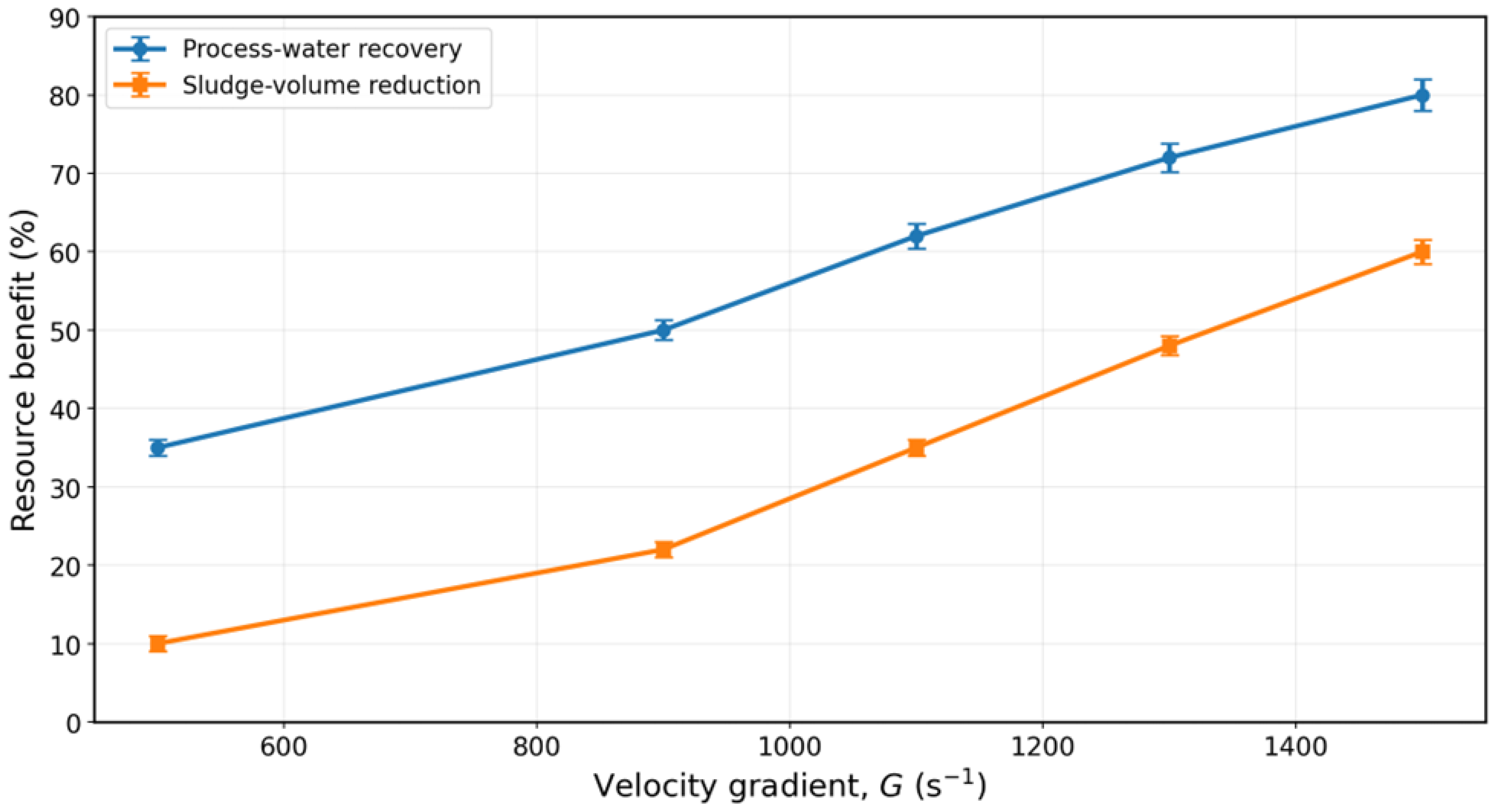
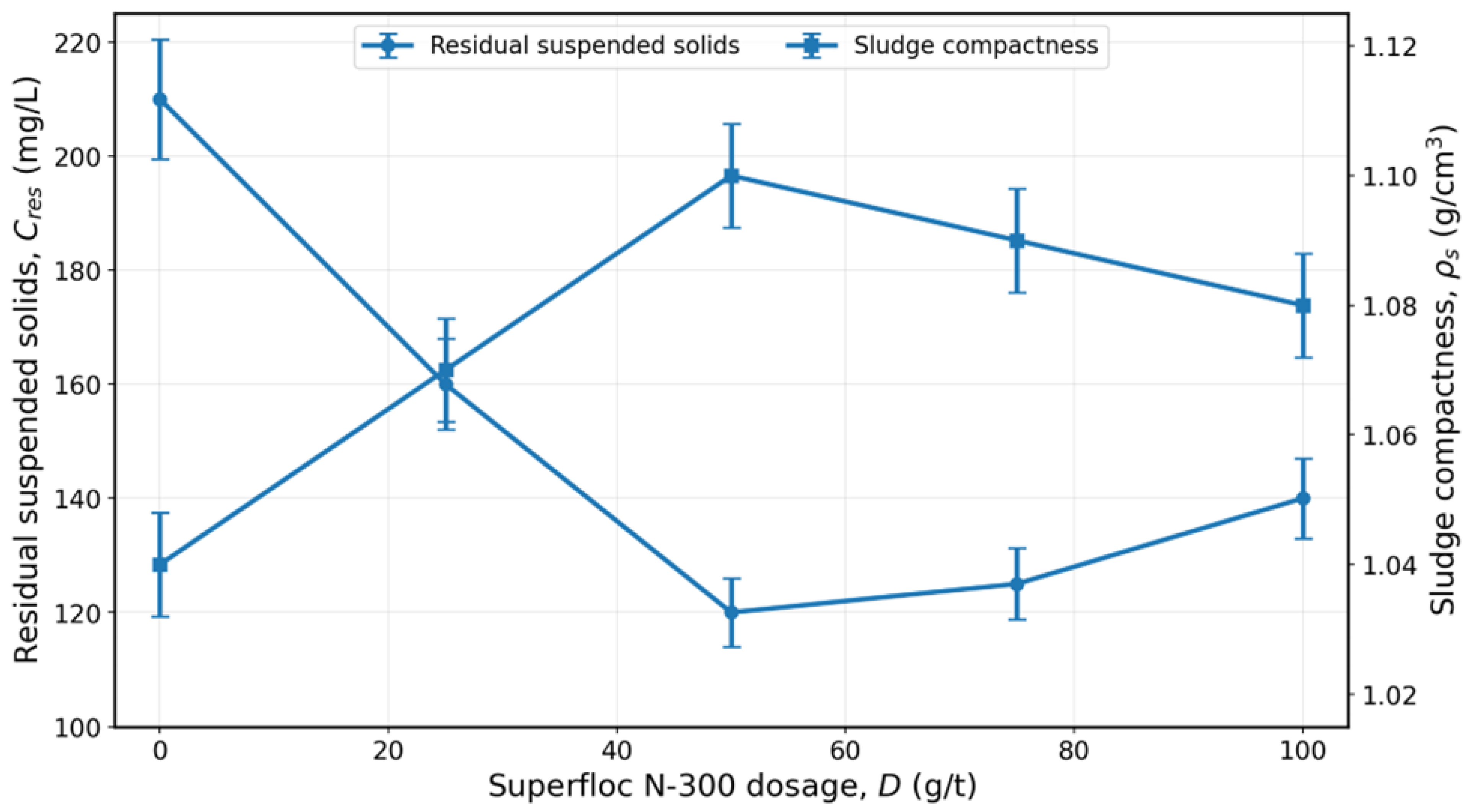
From an engineering standpoint, the preferred mode was not the condition with the highest separation efficiency, but the condition that best balanced clarified-liquid quality, reagent dosage, treatment time, process-water recovery, sludge-volume reduction, and specific energy consumption. The operational optimum was required to satisfy the following criteria: ηsep ≥ 90%, Cres ≤ 130 mg/L, D ≤ 50 g/t, Rw ≥ 75–80%, Rs ≥ 40%, and Esp ≤ 0.30 kWh/m3. This multicriteria definition distinguishes the practically applicable operating range from the single condition that maximizes ηsep.





 and
and