Article

Experimental Study on the Dynamics of the “Fracture–Migration” Effect in Overburden Under Dynamic Disturbance

1
College of Energy and Mining Engineering, Xi’an University of Science and Technology, Xi’an 710054, China
2
Maiduoshan Coal Mine of Ningxia Coal Co., Ltd., National Energy Group, Lingwu 750408, China
3
Key Laboratory of Western Mines and Hazard Prevention of China Ministry of Education, Xi’an University of Science and Technology, Xi’an 710054, China
*
Author to whom correspondence should be addressed.
Current Address: Yangchangwan Coal Mine of Ningxia Coal Co., Ltd., National Energy Group, Lingwu 751409, China.
Appl. Sci. 2026, 16(13), 6532; https://doi.org/10.3390/app16136532
Submission received: 9 March 2026 / Revised: 17 April 2026 / Accepted: 17 April 2026 / Published: 30 June 2026

Abstract

To investigate overburden movement and three-zone development under far-field strong dynamic disturbance induced by instability of typical thick and hard overburden in western mining areas, a large-scale two-dimensional physical similarity simulation was conducted using the 11N0201 working face of Maiduoshan Coal Mine as the engineering background. Four test scenarios were designed: a baseline condition, dynamic loading, pressure-relief boreholes, and coupled disturbance. The results show that dynamic loading shortened the first weighting interval of the overburden by 45.5%, while the thicknesses of the caving zone and fracture zone increased to 15 cm and 42 cm, respectively, representing increases of 36.4% and 20.6% relative to the baseline condition. At the fully mined stage, fracture connectivity increased to 45%. A fracture intersection angle of <50°, connectivity of >40%, and abrupt aperture variation can be regarded as empirical semi-quantitative precursor indicators of a dynamic instability tendency in thick and hard overburden. By introducing prefabricated weak planes, roof pre-splitting guided the directional development of fractures and caving. Under coupled disturbance, the thickness of the fracture zone was reduced by 42.9% compared with that under dynamic disturbance alone, and the amplitude of displacement fluctuation decreased by 33.3%. These changes promoted a transition in overburden movement from an “unordered dislocation” state to a controllable state of “dynamic-disturbance-induced, directionally regulated stability”. These findings provide an experimental basis for early warning and prevention of overburden instability under far-field strong dynamic disturbance in western mining areas with thick and hard overburden.

1. Introduction

Coal resources in western China constitute a critical pillar of the nation’s energy security, and both mining depth and extraction intensity have increased in recent years. Under conditions of thick and hard overburden, dynamic problems induced by coal extraction have become increasingly prominent. During conventional mining, overburden movement and three-zone development generally exhibit orderly, progressive characteristics. However, thick and hard overburden structures are prone to instability under mining-induced disturbance and may trigger strong far-field dynamic disturbance. Such a loading not only markedly alters the movement pathways and fracture sequence of the overburden but also challenges the applicability of the traditional three-zone theory. Specifically, the extent of overburden failure expands, fracture networks become disorderly and interconnected, and the load-bearing capacity of key strata drops sharply, thereby posing a serious threat to the safe advance of the working face [1,2,3,4,5]. Therefore, clarifying the movement law of thick and hard overburden, the mechanism of fracture evolution, and the dynamic amplification effect on three-zone development under strong far-field dynamic disturbance and establishing corresponding instability criteria and prevention measures have become urgent scientific and engineering issues for safe coal mining in western China [6,7,8,9,10,11]. Mining of the No. 2 coal seam in Maiduoshan Coal Mine is commonly affected by intense strata behavior induced by thick and hard overburden. During extraction, the interaction between dynamic disturbance and overburden becomes increasingly complex, which not only gives rise to the hazard of a large-area hanging roof but also creates a risk of sudden fracture propagation and dynamic instability induced by disturbance [12]. It is therefore imperative to clarify the deformation behavior of the overburden under dynamic disturbance and to establish a hazard prediction and prevention framework.
As the principal carrier of dynamic-load transmission and release, the fracture network within the overburden directly controls the overall stability of the strata and the development height of the three zones [13]. In recent years, physical similarity simulation has played an important role in revealing the movement characteristics of overburden strata. Fu et al. [14] investigated the strata movement laws and spatial–temporal evolution characteristics of extremely thick, weakly cemented overburden under deep multi-seam mining, and revealed the collapse forms and migration patterns of such overburden under deep multi-seam mining conditions. He et al. [15] proposed the structural theory of a “V-shaped hinged arch” for shallow-buried coal seam groups and revealed the transformation law of the frictional mechanism in sub-key strata. Teng et al. [16] investigated the controlling effects of lithology and stratum structure on overburden damage and failure under high-intensity mining and identified the influencing factors of overburden damage range and failure morphology. With respect to three-zone division and dynamic monitoring, Yuan et al. [17] investigated the deformation mode and migration law of extremely thick conglomerate strata through large-scale three-dimensional similar model tests and distributed fiber optic sensing monitoring. Wang et al. [18] investigated the movement deformation laws and fracture characteristics of the high-position key stratum using DOFS and MPBX and accurately obtained the staged deformation and fracture characteristics of the high-position key stratum. Monitoring techniques such as microseismic monitoring and acoustic emission have also provided technical support for dynamic identification of overburden fracturing processes [19,20,21,22,23,24]. Nevertheless, existing studies have mainly focused on overburden responses under static or single-disturbance conditions, while insufficient attention has been paid to the special disturbance scenario associated with strong far-field dynamic disturbance. In particular, quantitative relationships among three-zone evolution, fracture-parameter variation, and instability risk under dynamic disturbance remain insufficiently understood, which limits the predictive capability of traditional theories under multiple working conditions and strong disturbances.
Against this background, this study takes the 11N0201 working face of Maiduoshan Coal Mine as the engineering background and employs a large-scale two-dimensional physical similarity simulation. Four scenarios were designed—baseline condition, dynamic loading, roof pre-splitting, and coupled disturbance—to simulate strong far-field dynamic disturbance and its coupling effect with pressure-relief measures. The objectives are as follows: (1) to reveal the movement law of thick and hard overburden, the fracture characteristics of key strata, and the dynamic evolution process of the three zones under strong far-field dynamic disturbance; (2) to establish quantitative criteria for overburden dynamic instability based on fracture geometry, connectivity, and aperture variation; and (3) to evaluate the control effectiveness of roof pre-splitting technology on overburden movement and three-zone development under dynamic disturbance. Ultimately, this study aims to develop an integrated technical pathway combining mechanism, criterion, and control strategy, thereby providing a theoretical basis and experimental support for the prevention and control of dynamic disasters in western mining areas with thick and hard overburden.

2. Materials and Methods

2.1. Engineering Background

The 11N0201 working face is located in the 11N mining district of Maiduoshan Coal Mine, at a burial depth of 282.7–361.7 m below the ground surface, with an average depth of 322.2 m. The strike length of the working face is approximately 950 m, and the dip length is approximately 200 m. To the east, it adjoins the planned 11N0204 working face; to the west, it is adjacent to the planned 11N0202 working face. Its southern boundary is connected to Auxiliary Transportation Roadway II and Belt Conveyor Roadway II in the 11N mining district, while its northern boundary extends into an undeveloped area. The open-off cut is located 65.8–89.4 m from the protective coal pillar of the 11N mining district [25].
The 11N0201 working face extracts the No. 2 coal seam, whose thickness ranges from 4.27 to 6.50 m, with an average thickness of 5.30 m. The seam dip angle varies from 1° to 18°, with an average of 9.5°, and the dip direction ranges from 324° to 45°. The Protodyakonov hardness coefficient of the coal seam is f = 2–3, and both bedding planes and joints are relatively well developed. The absolute gas emission rate is 0.06 m3/min, indicating a low-gas mine. The coal dust explosion index is 25.68%, implying an explosion hazard. The normal water inflow at the working face is 140 m3/h, with a maximum inflow of 196 m3/h. The strata temperature ranges from 25 to 26 °C, and no rockburst risk has been identified.
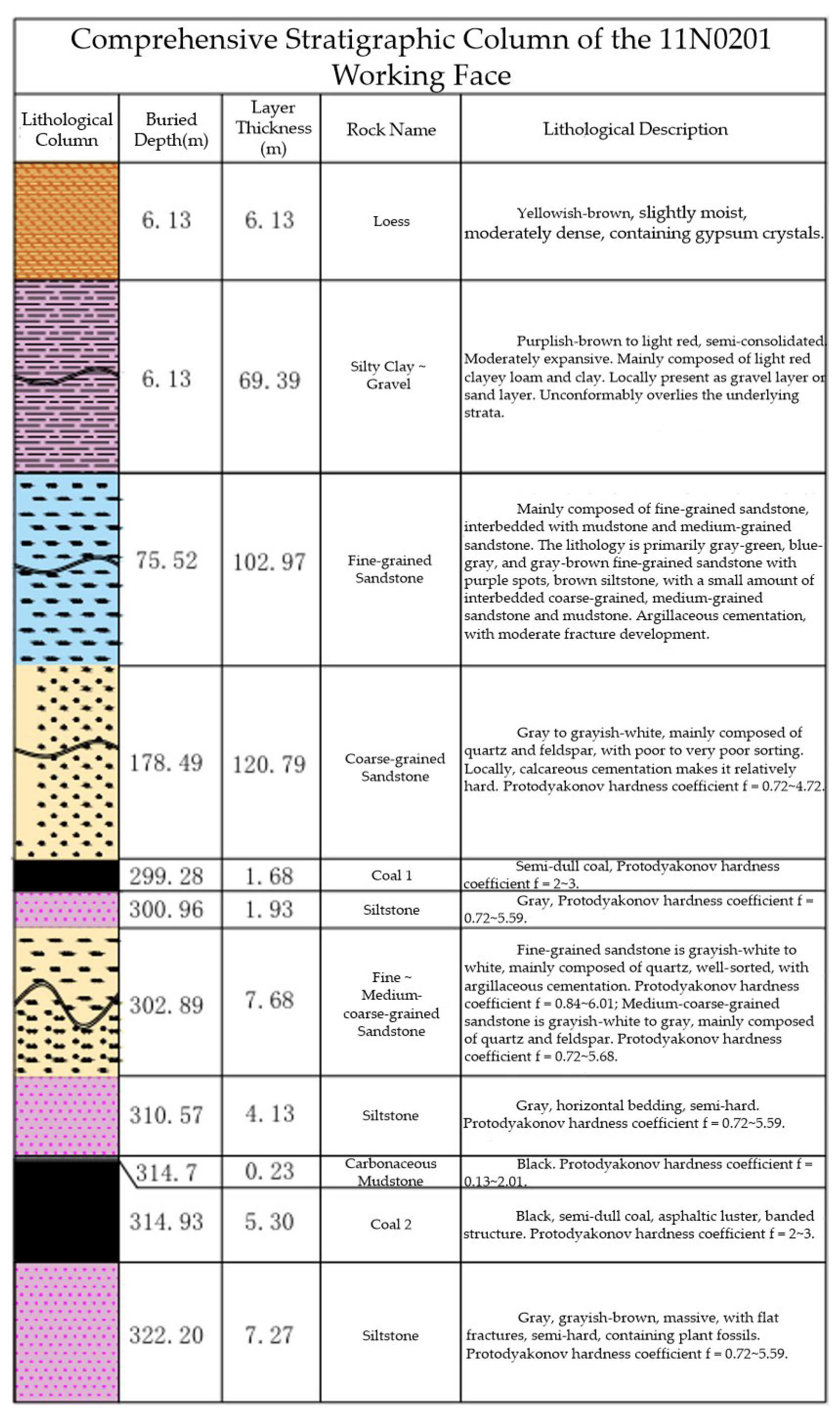
The roof of the 11N0201 working face is a structurally complex composite roof, whose key load-bearing structure is jointly formed by multiple thick and hard rock strata, as shown in Figure 1. The siltstone and fine- to medium-coarse-grained sandstone directly overlying the coal seam serve as the immediate roof and main roof controlling roof activity, respectively; both are characterized by high strength and substantial thickness. In the higher overlying strata, medium-coarse-grained sandstone acts as the key stratum and exerts dominant control over fracture and movement of the entire overburden above the panel. However, the stability of these thick and hard key strata is significantly weakened by multiple interbedded weak rock layers. In particular, an extremely weak carbonaceous mudstone occurs immediately beneath the immediate roof, forming a readily separable bedding interface, while expansive silty clay is present at the top of the stratigraphic sequence. Accordingly, the working face exhibits a distinct lithological feature characterized by alternating thick, hard rock strata and weak interlayers. The existence of coarse-grained sandstone key strata implies that the roof may accumulate substantial energy and induce intense strata pressure, whereas the weak interlayers render the fracture process more complex and heterogeneous. See Figure 1 for details.
Owing to the relatively large mining height, the complex overburden assemblage, and the influence of adjacent aquifers, a large goaf is likely to form during face advance. Under such conditions, the roof-bearing structure tends to evolve into a system dominated by “thick and hard key strata + weak interlayers”, resulting in pronounced strong strata behavior. Roof fracture is therefore likely to manifest as periodic weighting with a large fracture span and strong energy release. Meanwhile, water-rich aquifers are developed above the No. 2 coal seam. Excessive propagation of overburden fractures or excessive growth in the height of the three zones may lead to the formation of water-conducting pathways. When superimposed with dynamic loading disturbance, this will substantially increase the risks of roof collapse, water inrush, and other mining hazards. In summary, the 11N0201 working face is characterized by prominent strong strata behavior and considerable difficulty in roof control. It is therefore necessary to reveal the coupled mechanism of the “fracture–migration” dynamic effect in the overburden through indoor physical similarity simulation so as to provide a technical basis for strata-pressure control and safe mining in the field.

2.2. Similarity Ratios and Similar Materials

2.2.1. Determination of Similarity Ratios

Considering the dimensions of the laboratory test platform and the actual geological conditions of the 11N0201 working face, the key similitude parameters for constructing the physical similarity model were determined as follows [26]:
The geometric similarity ratio:
C g = G l G L = 1 : 200 ,
where C g —geometric similarity ratio; G l —model dimension parameter; and G L —prototype dimension parameter.
The time similarity ratio:
C t = G l G L = C g = 1 : 14.1 ,
where C t —time similarity ratio.
The bulk density similarity ratio:
C d = γ l γ L = 1 : 1.5 ,
where C d —unit weight similarity ratio; γ l —average unit weight of similar material; and γ L —average unit weight of prototype rock mass.
And, the stress similarity ratio:
C σ = C g C d = 1 : 300 ,
where C σ —stress similarity ratio.

2.2.2. Mix Design of Similar Materials

The similarity design adopted in this study follows conventional geomechanical similarity criteria and is intended for qualitative and semi-quantitative comparative analysis. It does not constitute a strict dynamic similitude framework.
The similar materials were prepared using river sand as the aggregate, lime and gypsum as the cementitious materials, and water as the binding agent. Coarse mica powder was laid between different rock strata as an interlayer material to simulate the interface characteristics of stratified rock masses [26]. Based on the physical and mechanical parameters of the prototype coal and rock strata, the mix proportions of the simulation materials for each stratum were determined through orthogonal testing. According to the geological exploration data for the 11N0201 working face and the selected similarity ratios, the key physical and mechanical parameters of each rock stratum were extracted to provide a basis for subsequent calculations. The mix proportions of representative similar materials and their core parameters are presented in Table 1.

2.3. Model Construction and Working Condition Design

2.3.1. Model Dimensions and Monitoring Scheme

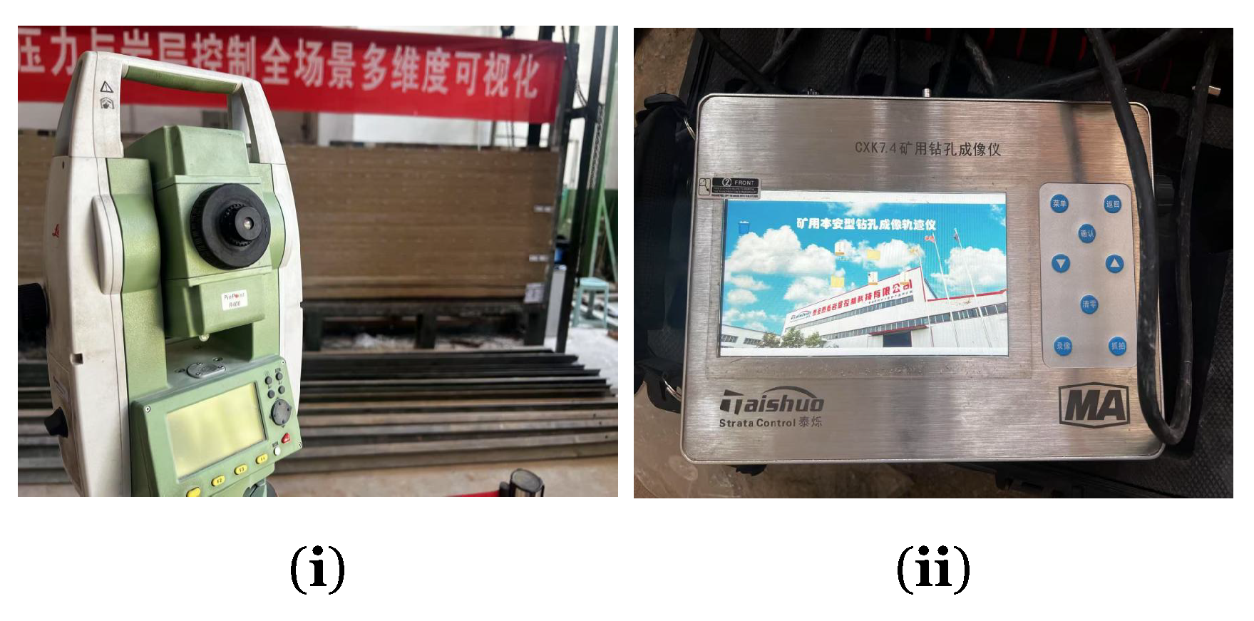
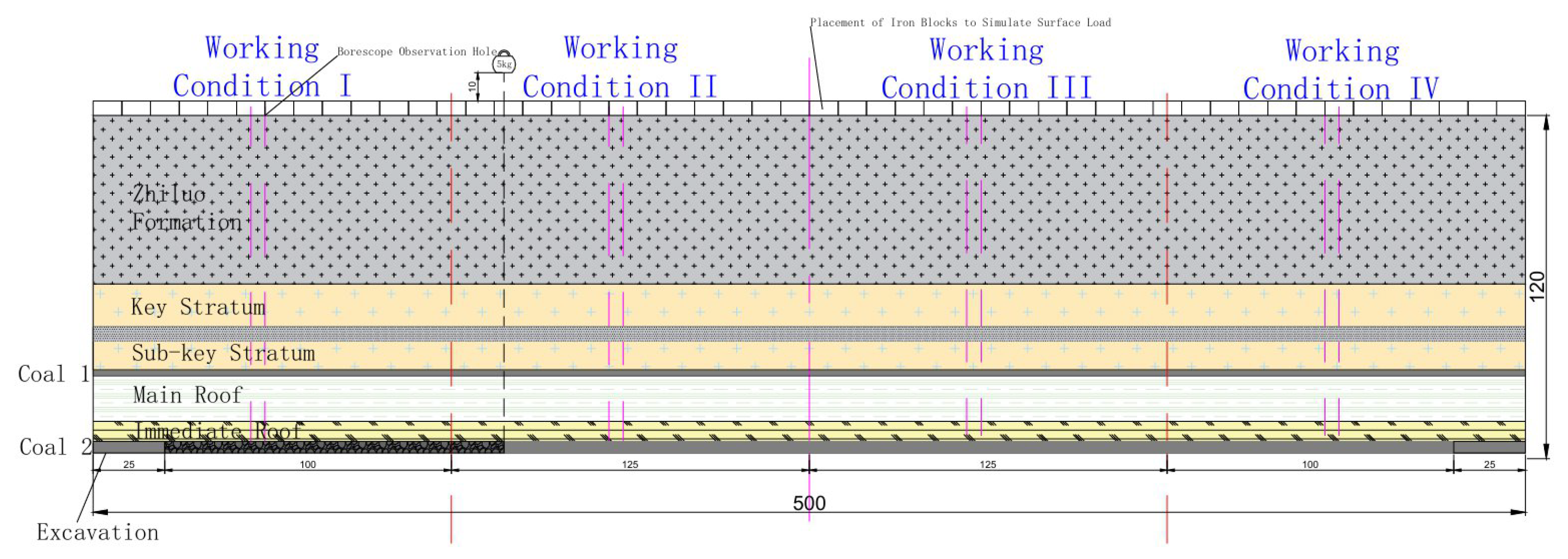
The physical model had overall dimensions of 5.0 m × 0.2 m × 1.2 m. Iron blocks were placed on top of the model to simulate the load of the overlying strata. A total of 12 rows of monitoring points, denoted A–L, were arranged on the front surface of the model. Overburden displacement was monitored using a PENTAX R-322NX optical total station (PENTAX Precision Co., Ltd. (Tokyo, Japan)). Displacement values were calculated from coordinate differences, and displacement contour maps were generated by Surfer interpolation. Comparative analyses of parameters under multiple working conditions were performed to quantitatively evaluate control effectiveness.
In addition, four borehole observation ports were reserved at positions of 62.5 cm, 187.5 cm, 312.5 cm, and 437.5 cm in the model and numbered 1# to 4#, respectively. A CXK7.4 mine borehole imager (Tai’an Taishuo Rock Stratum Control Technology Co., Ltd. (Tai’an, China)) was used to monitor the development characteristics of overburden fractures. This instrument provides high accuracy and is suitable for large-scale field monitoring. In the present experiment, it was used to monitor fracture development in the overburden. By observing fracture occurrence characteristics, the migration behavior of the overburden was analyzed, and parameters under different working conditions were comparatively evaluated. See Figure 2 for details.

2.3.2. Design of Experimental Working Conditions

To investigate the effects of dynamic loading and roof pre-splitting on overburden caving and movement, four working conditions were designed, and mining under each condition advanced continuously along the strike direction of the model. To avoid additional stress concentration induced by coal pillars, ensure continuous transmission of the mining-induced stress field, and achieve accurate control of single variables, no coal pillar was reserved between adjacent working conditions. This arrangement ensured the scientific validity of multi-condition comparisons and improved the applicability of the results to engineering practice. See Figure 3 for details.
  • Condition I (baseline/no special treatment): The advancing range was 25–125 cm, simulating conventional mining conditions without dynamic loading or roof pre-splitting.
  • Condition II (dynamic loading applied): The advancing range was 125–250 cm. Far-field strong dynamic disturbance was simulated by allowing a 5 kg kettlebell to fall vertically from a height of 10 cm above the model top at the vertical projection of the working face as the face advanced. In this way, field dynamic disturbances such as impact loading and periodic weighting under thick and hard overburden conditions were equivalently transformed into an additional dynamic load acting on the model roof. This condition was used to characterize overburden caving behavior and fracture evolution under dynamic disturbance induced by thick and hard overburden.
  • Condition III (roof pre-splitting): The advancing range was 250–375 cm. Pressure-relief boreholes were arranged at 10 cm intervals at the 25 cm level of the model, and no dynamic load was applied.
  • Condition IV (dynamic loading + roof pre-splitting): The advancing range was 375–475 cm. Dynamic loading and roof pre-splitting were applied simultaneously. The results were compared with those of Conditions I and II to evaluate the control effectiveness of the combined measures.

2.4. Identification of Key Strata

Key strata are the core load-bearing layers that control the overall movement and stability of the overlying strata above the mining panel. Their fracture and movement directly determine the caving pattern of the overburden, the extent of fracture development, and the distribution characteristics of the three zones [27].
Based on key-strata theory, the main key stratum and sub-key stratum were identified by quantitatively calculating the flexural rigidity (EI) and load-transfer characteristics of each rock layer [28,29,30], in combination with the stratigraphic column and the physical and mechanical parameters of the coal and rock strata at the 11N0201 working face. The results indicate that the main key stratum of the overlying strata at the 11N0201 working face is the No. 17 coarse-grained sandstone layer, which controls the overall movement of the overburden and the upper limit of three-zone development; once this layer fractures, the fracture zone no longer propagates upward. The sub-key stratum is the No. 19 coarse-grained sandstone layer, which serves as a transitional layer between the main key stratum and the underlying weak rock strata. Its bed separation and fracture directly affect fracture density and connectivity in the middle and lower parts of the fracture zone.

2.5. Definition of the Three Zones and Their Empirical Formulas

During coal seam extraction, the overlying strata are affected by mining-induced disturbance and can be divided into three zones according to their failure and deformation characteristics: the caving zone, fracture zone, and bending subsidence zone. These zones are distributed sequentially from bottom to top, and the degree of deformation and damage gradually decreases upward. See Table 2 for details.

3. Results

3.1. Characteristics of Overburden Caving and Movement, and Three-Zone Division Under the Baseline Condition (No Special Treatment)

3.1.1. Development of Mining-Induced Fractures, and Characteristics of Overburden Caving and Movement

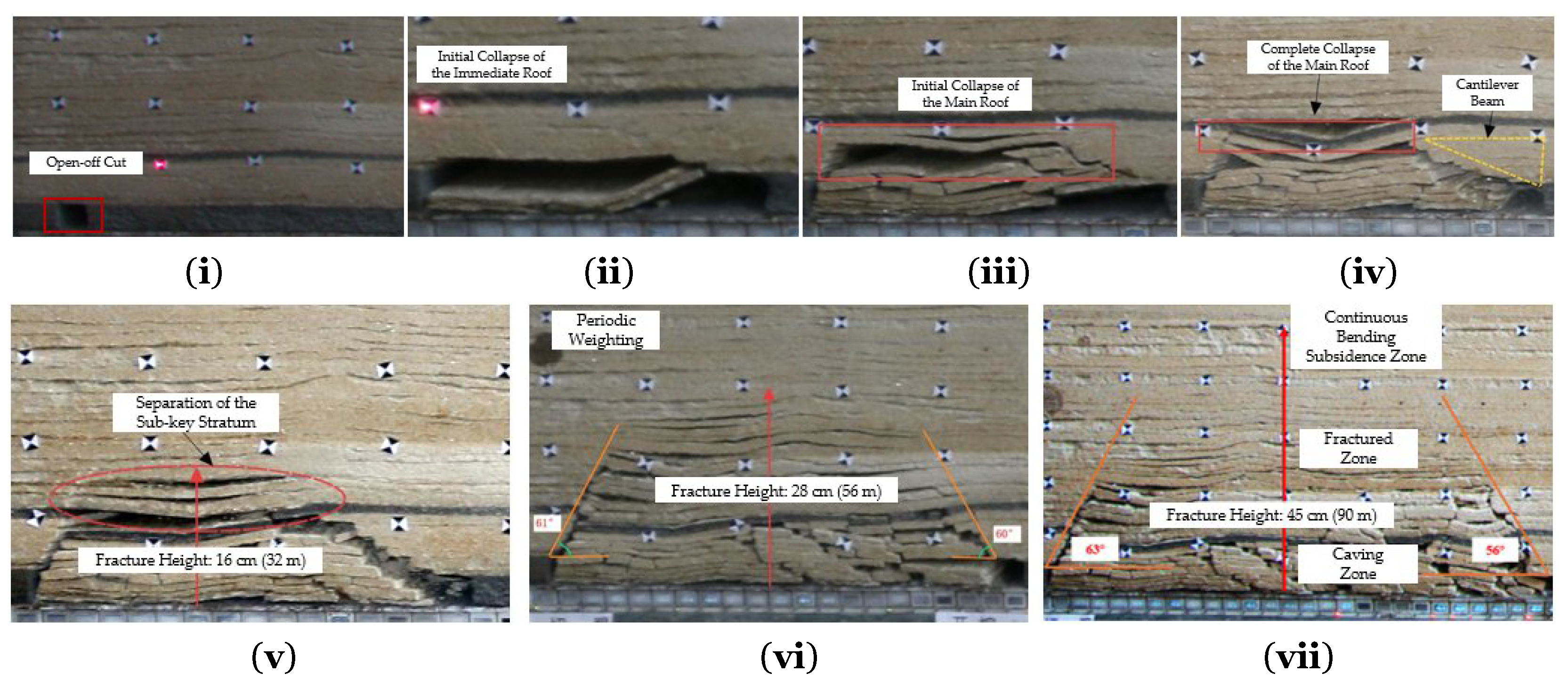
Under the baseline condition, the overburden caving process exhibited typical progressive-failure characteristics, with orderly caving patterns and pronounced periodicity. Fracture development was dominated by propagation along bedding planes. See Figure 4 for details.
After the working face was opened, only slight bending deformation occurred in the immediate roof and main roof, and no obvious block fracture or large-scale caving was observed. Overburden movement was mainly characterized by slow overall subsidence, with both vertical and horizontal displacements remaining small. Only a slight subsidence trough formed above the goaf.
When the working face advanced to approximately 61 cm, the immediate roof underwent its first caving event. The caved rock blocks were short-columnar in shape and relatively small in size, and the caving range was concentrated in a local area directly above the goaf. At this stage, fractures on the overburden surface were sparse and mainly developed along bedding planes, with no obvious cross-cutting. The fracture propagation direction was generally consistent with the advancing direction of the working face.
As the working face further advanced to 69 cm, the first weighting occurred. A large number of fractures developed in the main roof, accompanied by bed separation, and the roof eventually fractured and collapsed. The first weighting interval was 44 cm, after which the overburden entered the periodic-weighting stage, with a periodic weighting interval of 16 cm. The caved rock blocks gradually accumulated to form a supporting structure, while the number of overburden fractures increased slowly and their orientation remained relatively orderly. Overburden movement gradually changed from “disordered caving of fragmented rock masses” to “interlayer separation + orderly rotation”.
When the working face advanced to 125 cm, overburden caving tended to stabilize, and surface fracture development had basically ceased. Fractures were mainly concentrated directly above the goaf and exhibited a stratified distribution pattern. The upper limit of fracture development was constrained by the main key stratum and did not extend upward into the bending subsidence zone. The vertical subsidence of the main key stratum remained within 1–2 cm, while its horizontal displacement was close to zero, indicating that it still functioned overall as a stable load-bearing beam.
Based on the fracture development and the caving–movement process, the overburden under the baseline condition can be divided into the following zones: the thickness of the caving zone is 11 cm (0–11 cm), where the strata were completely fractured and collapsed; the thickness of the fracture zone is 34 cm (11–45 cm), where fractures were well developed but the overall integrity of the strata remained relatively intact, with orderly connectivity mainly along bedding planes; and the thickness of the bending subsidence zone is 75 cm (45–120 cm), where the strata underwent only slow bending and overall subsidence. The boundaries among the three zones were distinct, the overall overburden movement process was relatively gentle, and the dynamic effect was weak.

3.1.2. Analysis of Borehole Imaging Monitoring

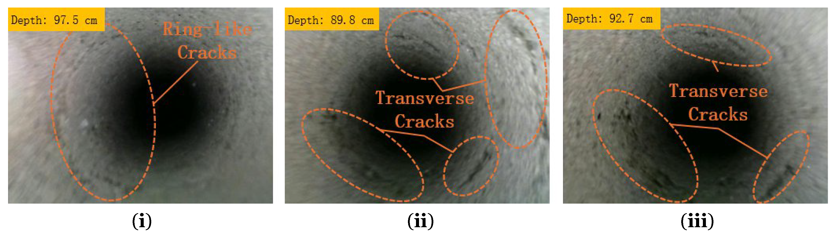
Initial stage: Only a small number of primary fractures were observed in Borehole 1#, with a relatively low fracture density of approximately 4.1 fractures/m. Their spatial distribution was scattered and showed no obvious preferred orientation, indicating that the overburden as a whole remained in an elastically balanced state.
Critical stage: As mining-induced stress concentration intensified, the number of fractures observed in the borehole gradually increased, and the fracture density rose to 7.3 fractures/m. The fractures propagated preferentially along bedding planes, but their connectivity remained poor, and no secondary fractures were observed.
Fully mined stage: Fractures in the borehole became orderly and interconnected along bedding planes, forming a fracture network that gradually became sparser upward from the lower strata. The fracture density reached 10.5 fractures/m, with connectivity of approximately 22% and an average aperture of 1.2 mm. See Figure 5 for details.
All fracture parameters (fracture ratio, connectivity, aperture, and density) were obtained based on borehole imaging through manual interpretation assisted by semi-automatic image statistics. During the measurement, the developed fractures in the same borehole section were identified and marked three times independently, and the average value was taken as the final result to reduce human error. Fracture connectivity was calculated as the percentage ratio of the total length of interconnected penetrating fractures to the total length of all identified fractures; aperture and density were measured and counted along the borehole depth at equal intervals. Multiple repeated measurements show that the variability of each parameter is within 5%, which ensures the reliability and stability of the statistical results. The quantitative data can objectively reflect the development and penetration characteristics of overburden fractures under static and dynamic loading conditions.

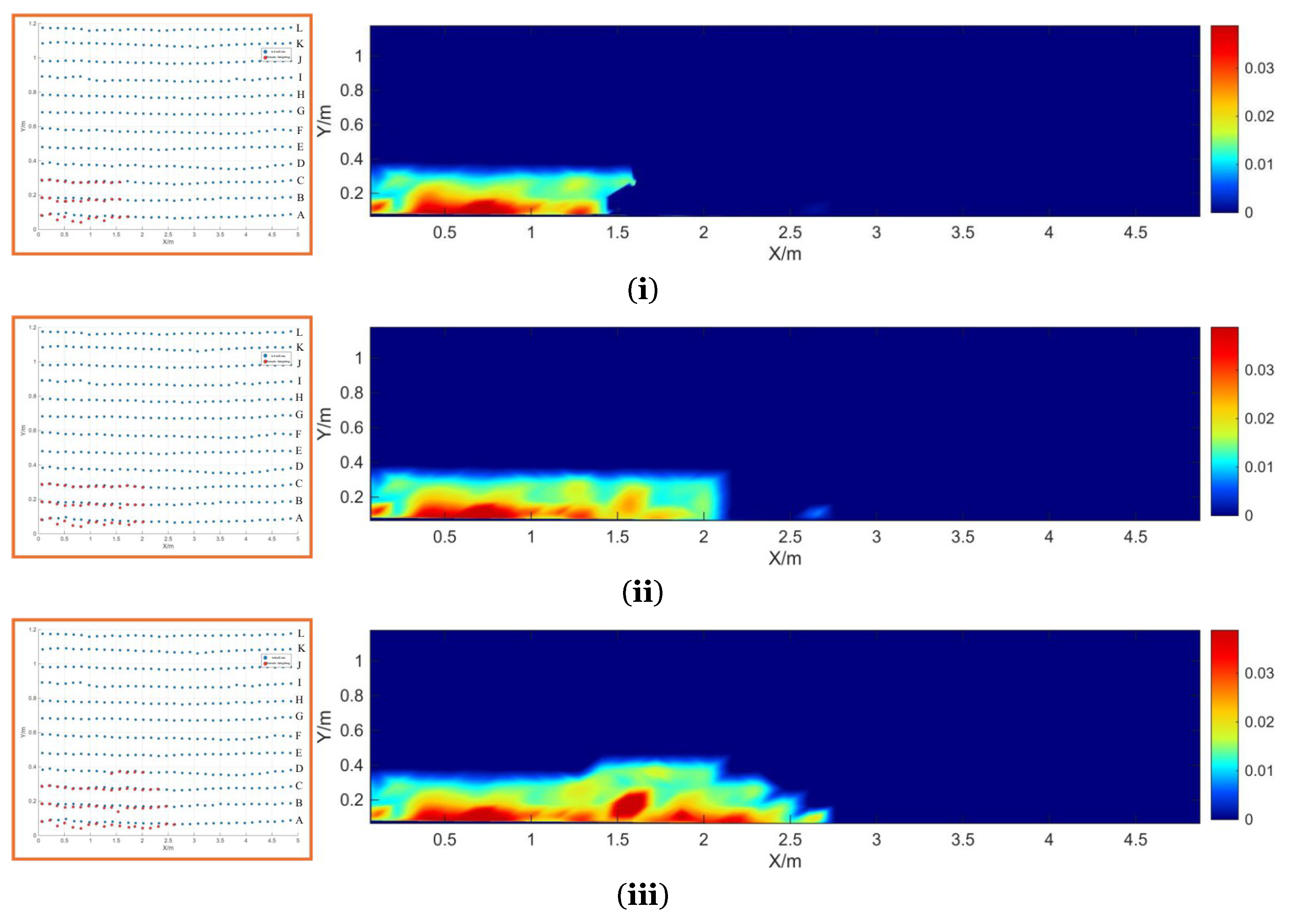
3.1.3. Analysis of Total Station Displacement Monitoring

Based on the displacement data collected from monitoring rows A–L, the displacement evolution characteristics of the overburden under Condition I are summarized as follows:
  • First weighting: The high-displacement zone was concentrated in the region of monitoring points A3–A6, where the maximum vertical displacement reached 2.16 cm, showing a distribution pattern characterized by local point-like concentration. The area of the high-displacement zone accounted for approximately 8% of the total model area. The color gradient in the displacement contour map was gentle, with no obvious abrupt transition zone, indicating that the displacement induced by fracture of the immediate roof and main roof was mainly concentrated in the area directly affected by mining-induced stress. Stress transfer within the overburden was relatively uniform, and no abrupt stress change was observed.
  • Periodic weighting: The high-displacement zone gradually expanded from row A to row B, and the displacement at monitoring points B1–B6 increased to 0.21 cm. The area of the high-displacement zone expanded to 12%, while the color gradient remained smooth. The contour map shows that the displacement-diffusion direction was consistent with the advancing direction of the working face, indicating that the overburden had entered a stage of periodic and stable subsidence. Strata movement remained well coordinated, and no risk of local instability was identified.
  • End of mining: The high-displacement zone stabilized in the region of monitoring points B3–B4, where the maximum displacement was 0.30 cm, and the area of the high-displacement zone shrank to 6%. The contour map as a whole exhibited a pattern of uniform transition. Combined with the arch-shaped structural characteristics of the overburden, this indicates that stress redistribution within the overburden had been completed and that the structure had become stable. The amplitude of displacement fluctuation was less than 0.05 cm, satisfying the basic requirements for stable control of overburden in deep mining. See Figure 6 for details.

3.2. Characteristics of Overburden Caving and Movement, and Three-Zone Division Under Dynamic Loading Disturbance

3.2.1. Development of Mining-Induced Fractures, and Characteristics of Overburden Caving and Movement

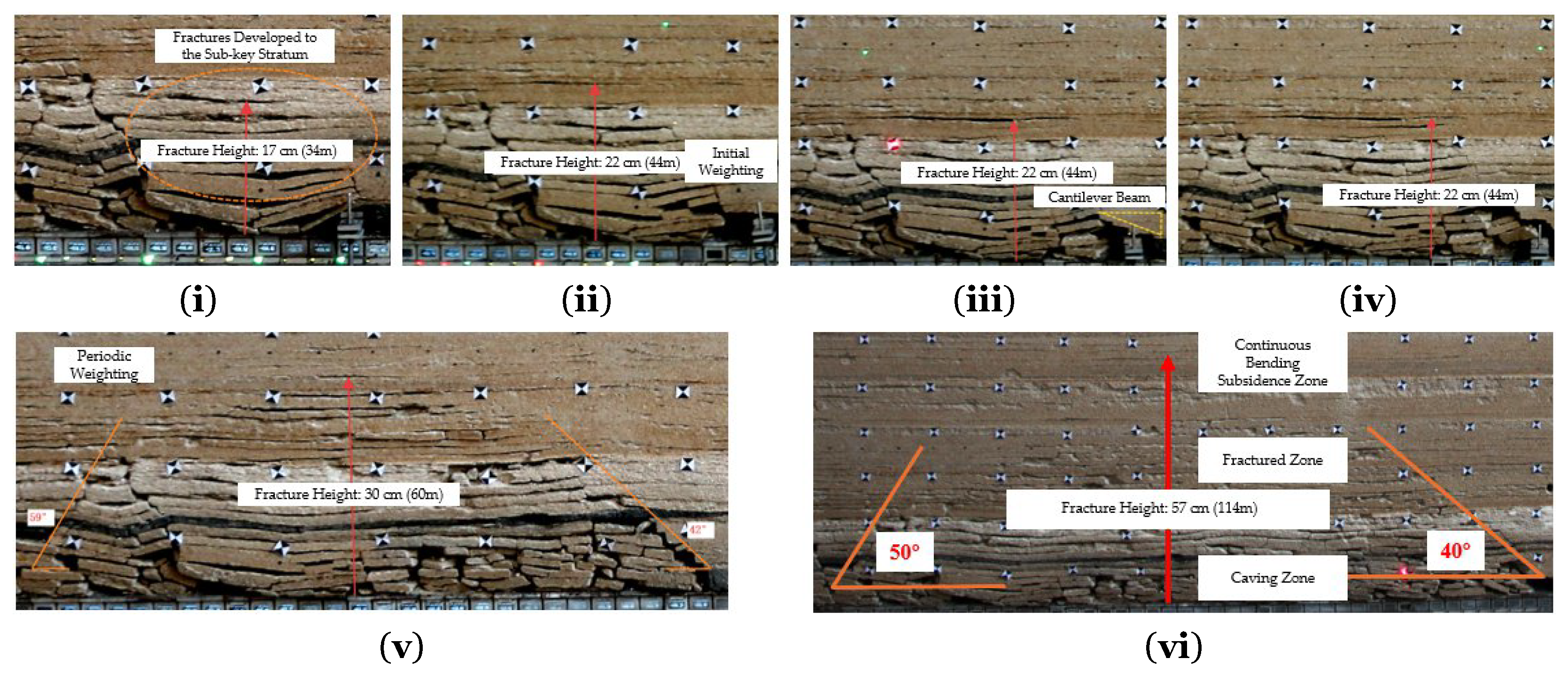
Under the dynamic-loading condition, an instantaneous impact was applied by allowing a kettlebell to fall vertically from a height of 10 cm above the model top as the working face advanced. Under dynamic disturbance, overburden caving exhibited pronounced impact-response characteristics, including earlier caving, greater caving intensity, and a stronger tendency toward disordered surface-fracture development. See Figure 7 for details.
At the initial stage of the dynamic-loading condition, the fracture pattern was similar to that under the baseline condition, and overburden deformation was still dominated by elastic bending. When the working face advanced to 145 cm, the immediate roof underwent impact-induced caving. The caved rock blocks became larger and more severely fragmented, and local rock ejection was observed, indicating that caving occurred significantly earlier. The movement mode changed from slow sliding to sudden dislocation and rapid slip, with vertical displacement reaching 12–15 cm and horizontal displacement increasing to 5–8 cm. The shallow overburden therefore exhibited an extremely strong dynamic response. Subsequently, when the working face advanced to 149 cm, the first weighting of the main roof occurred, accompanied by fracture and collapse. The first weighting interval was 24 cm, and the caving process was characterized by block collision and disordered overturning, with obvious displacement jumps induced by abrupt stress release. As the working face further advanced to 193 cm, it entered the middle section of the dynamic-loading zone and was essentially no longer affected by Condition I. At this stage, the overburden entered the periodic-weighting phase, during which the main roof exhibited periodic caving with an interval of 12 cm.
When the working face advanced to 250 cm, the upper limit of fracture-zone development extended upward to 42 cm. Although the main key stratum did not collapse as a whole, a large number of secondary fractures developed under strong dynamic loading. Its deformation pattern changed from pure bending to bending plus slight dislocation, with vertical subsidence increasing to 3–4 cm and a certain degree of horizontal displacement also occurring. The load-bearing capacity of the key stratum was therefore markedly weakened, and the overall movement of the overburden evolved from orderly coordinated movement into multi-level disordered dislocation.
Overall, under the dynamic-loading condition, the three zones expanded upward as a whole: the thickness of the caving zone increases to 15 cm (0–15 cm), with its thickness increasing by approximately 36% compared with that under the baseline condition and the height of the fragmented rock mass increasing significantly; t, the thickness of the fracture zone, increases to 42 cm (15–57 cm), where fractures were dense and highly disordered, and the upper limit of fracture development approached the main key stratum; and the thickness of the bending subsidence zone is 63 cm (57–120 cm), within which a certain number of secondary fractures were still observed. The boundaries among the three zones became increasingly indistinct, indicating that dynamic loading significantly amplified the intensity and extent of overburden failure and movement.

3.2.2. Analysis of Borehole Imaging Monitoring

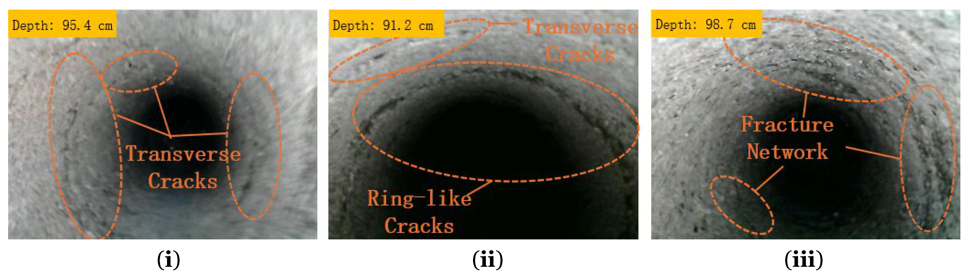
Initial stage: The fracture morphology observed in Borehole 2# was similar to that under the baseline condition and was still dominated by primary fractures and a small number of tensile cracks. Fracture density remained low and connectivity was poor, at approximately 4.0 fractures/m.
Critical stage: Fractures initiated explosively, and their number increased rapidly, with fracture density rising to 9.8 fractures/m. The fracture-propagation pattern changed from a single bedding-controlled direction to multidirectional expansion, and a large number of secondary fractures were generated from fracture tips, indicating a significant intensification of stress concentration.
Fully mined stage: Fractures in the borehole became cross-connected, forming a highly disordered fracture network. Local abrupt changes in fracture aperture were also observed, indicating that energy was released intensively within a short period. Connectivity increased to 45%, the average aperture reached 1.5 mm, and fracture density rose to 12.2 fractures/m. See Figure 8 for details.

3.2.3. Analysis of Total Station Displacement Monitoring

Based on the displacement data collected from monitoring rows A–L, the displacement evolution characteristics of the overburden under Condition II are summarized as follows:
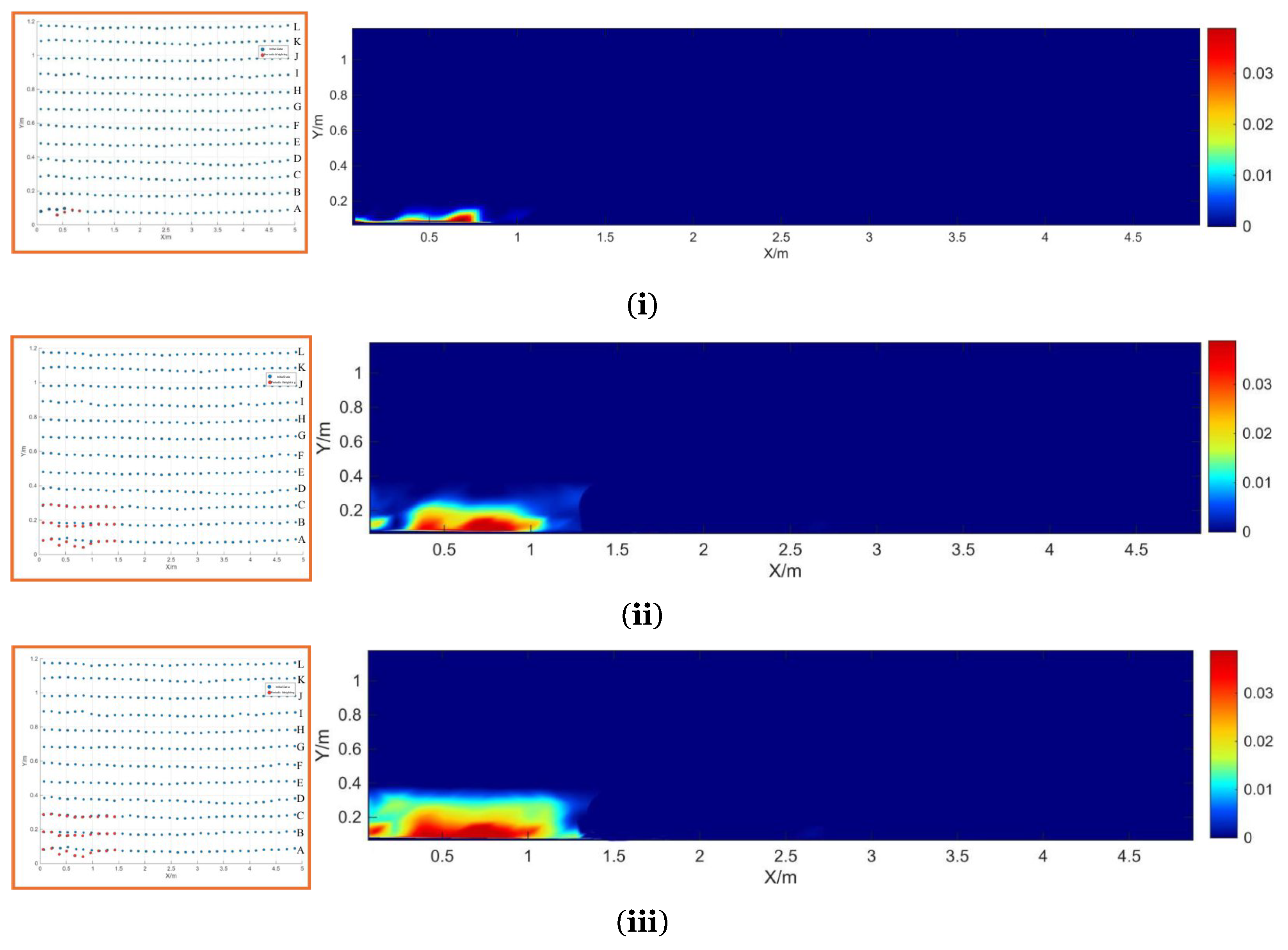
  • First weighting: The high-displacement zone was concentrated in the region of monitoring points A9–A10, where the maximum vertical displacement reached 1.20 cm. The high-displacement zone exhibited an irregular patch-like diffusion pattern, accounting for 15% of the total model area. The displacement contour map showed a distinct color-transition band, within which the displacement gradient reached 0.3 cm/m, significantly higher than that under the baseline condition. This indicates that dynamic loading induced abrupt stress release, leading to concentrated overburden displacement and accelerated displacement propagation, with a potential risk of local impact instability.
  • Periodic weighting: The high-displacement zone rapidly expanded toward row B, where the maximum displacement at the monitoring points reached 0.30 cm. The area of the high-displacement zone increased to 20%, and the number of abrupt color-transition bands increased to three, while the displacement gradient within these zones remained at 0.25 cm/m. The contour map shows that the displacement-propagation direction exhibited multidirectional deviation, with the maximum deviation angle from the advancing direction of the working face reaching 15°. This suggests that dynamic loading disrupted the coordination of overburden movement and intensified interlayer dislocation.
  • End of mining: The high-displacement zone was distributed in the region of row D, where the maximum displacement reached 0.30 cm. The high-displacement zone showed a scattered point-like distribution pattern, accounting for 18% of the total model area. The frequency of color fluctuation in the contour map reached 5 times/m2, which was significantly higher than that under the baseline condition. Combined with the characteristics of the overlap zone of the overburden arch-shaped structure, this indicates that dynamic loading resulted in non-uniform stress distribution within the overburden and reduced structural stability. Therefore, additional support measures are required to prevent abrupt displacement changes. See Figure 9 for details.

3.3. Characteristics of Overburden Caving and Movement, and Three-Zone Division Under Roof Pre-Splitting Regulation

Roof pre-splitting guided the directional failure of the overburden by introducing prefabricated weak planes. As a result, surface-fracture development exhibited more orderly and concentrated characteristics, and dynamic disturbance was significantly weakened.
The three zones were divided as follows: the thickness of the caving zone is 10 cm (0–10 cm), the thickness of the fracture zone is 18 cm (10–28 cm), and the thickness of the bending subsidence zone is 92 cm (28–120 cm). The thickness of the fracture zone was markedly reduced, indicating that roof pre-splitting achieved active regulation of the spatial extent of the three zones.

3.4. Characteristics of Overburden Caving and Movement, and Three-Zone Division Under the Coupled Disturbance of Dynamic Loading and Roof Pre-Splitting

Under the coupled condition, dynamic loading accelerated the caving process, whereas roof pre-splitting constrained the caving direction. Through the combined action of these two factors, overburden caving exhibited the characteristic pattern of dynamically accelerated caving and directionally constrained movement.
The three-zone division results were as follows: the thickness of the caving zone is 13 cm (0–13 cm), the thickness of the fracture zone is 24 cm (13–37 cm), and the thickness of the bending subsidence zone is 83 cm (37–120 cm). The fracture-zone thickness remained stable at 24 cm, which was significantly lower than that under the dynamic-loading condition. These results indicate that, while maintaining a certain caving intensity and weighting frequency, roof pre-splitting effectively suppressed excessive fracture propagation caused by dynamic loading and significantly enhanced the structural stability of the overburden.

4. Discussion

Under impact loading conditions associated with thick and hard overburden, the response of the overburden is manifested as coordinated evolution of the deformation field, fracture field, and dynamic field. Based on a comparative analysis of multiple working conditions, this study interprets the coupling mechanism of these three fields within a unified framework of macroscopic movement, mesoscopic fractures, and dynamic effects and further proposes quantifiable criteria for identifying dynamic instability. This highlights the innovation of the present study in advancing from qualitative description to quantitative identification.

4.1. Mechanism of Overburden Deformation Evolution

4.1.1. Evolution Mechanism of the Three Zones in the Overburden

The development characteristics of the three zones exhibit a significant coupling relationship with the working conditions, and their evolution is essentially the result of coordinated action of the stress field and energy field. After completion of mining under the four working conditions, the overburden movement parameters for each condition were compiled, as shown in Table 3. Under the baseline condition, the boundaries of the three zones were distinct, with a caving-zone thickness of 11 cm and a fracture-zone thickness of 34 cm; these values agree well with those calculated using the empirical formulas. This reflects the orderly nature of overburden movement under conventional mining conditions.
Under the baseline condition, the three zones were clearly delineated, and both caving and movement proceeded relatively gently. Essentially, this is because mining-induced stress was transmitted and released progressively through the overburden. The caving zone mainly consisted of the immediate roof and the overlying weak strata, which underwent stratified caving as the working face advanced and gradually formed a fragmented accumulation body with high porosity. The fracture zone was composed of the main roof and the strata above it up to the lower part of the main key stratum, within which a relatively orderly fracture network developed along bedding planes under mining disturbance. Owing to its relatively large flexural rigidity and fracture interval, the main key stratum remained in a beam-like load-bearing state for a long period, undergoing only slight elastic bending; accordingly, the bending subsidence zone remained relatively thick.
The high-energy stress waves induced by dynamic disturbance were superimposed on the mining-induced static stress field, forming local zones of dynamic stress concentration. This significantly reduced the strength of the rock mass and triggered impact-induced caving of the immediate roof, thereby increasing the thickness of the caving zone. Meanwhile, by imposing coupled dynamic tensile–shear stresses, dynamic loading promoted rapid propagation of fracture tips, increased the number of secondary fractures and the fracture ratio, and drove the fracture network to become disorderly interconnected and extend upward, thereby expanding the fracture zone. In addition, under dynamic disturbance, the main key stratum experienced both bending and slight dislocation, causing damage to its load-bearing structure and weakening its beam-like load-bearing capacity. As a result, its restraining effect on upward fracture propagation was reduced, leading to increasingly indistinct boundaries among the three zones and a decline in overall structural stability.
Dynamic loading breaks the original stress equilibrium of the overburden by imposing instantaneous impact energy, thereby triggering a combined effect of stress superposition and abrupt energy release. Impact-induced caving of the immediate roof increased the thickness of the caving zone to 15 cm, representing an increase of 36.4% compared with that under the baseline condition. The fracture interval of the main roof was reduced to 32 cm, and the disordered collision and cutting of rock blocks caused the thickness of the fracture zone to expand to 42 cm, corresponding to an increase of 20.6%. Meanwhile, the thickness of the bending subsidence zone decreased to 63 cm, and the boundaries among the three zones became increasingly indistinct. To quantitatively characterize the amplifying effect of dynamic loading on the caving zone and fracture zone, a dynamic-loading influence coefficient, k, was introduced, by which the thicknesses of the two zones satisfy Hd = k·Hm, where Hd is the thickness under dynamic disturbance, Hm is the thickness under the baseline condition, and k is the dynamic-loading influence coefficient (k > 1). This relationship quantitatively characterizes the driving effect of dynamic loading on expansion of the three zones.
The dynamic loading simulated by the falling weight is only a comparative laboratory disturbance, not an accurate reproduction of field dynamic events. The experimental conclusions are applicable to laboratory similar simulation conditions, and direct application to field engineering requires further verification and calibration.

4.1.2. Overburden Migration Law

The evolution of overburden displacement directly reflects structural stability, and the displacement characteristics differ significantly under different working conditions. Based on the maximum vertical displacement, displacement-fluctuation amplitude, and displacement-evolution data at different mining stages obtained from total station monitoring, the differences in overburden displacement under multiple working conditions were compared, as shown in Table 4.
Under the dynamic-loading condition, the displacement-fluctuation amplitude throughout the mining process reached 1.2 cm, which was 24 times that under the baseline condition. At the end of mining, the high-displacement zone accounted for 18% of the total area and exhibited a scattered point-like distribution pattern. This indicates that dynamic impact disrupted the continuity and coordination of overburden movement and could easily induce intermittent displacement jumps, thereby constituting an important external factor leading to dynamic instability.
The maximum overburden displacement under dynamic disturbance is 1.8–2.2 times that under static loading, and the displacement fluctuation amplitude is positively correlated with the dynamic disturbance intensity, with the fluctuation coefficient increasing from 0.12 (static condition) to 0.35 (dynamic condition).
Roof pre-splitting reduced the displacement-fluctuation amplitude to 0.5 cm by directionally releasing displacement energy. The high-displacement zone exhibited a directional banded distribution pattern and accounted for only 7% of the total area, reflecting the constraining effect of the prefabricated weak planes on the movement trajectory of the overburden. Under the coupled condition, the displacement-fluctuation amplitude was less than 0.8 cm, representing a reduction of 33.3% compared with that under the dynamic-loading condition. The area proportion of the high-displacement zone decreased to 9% and exhibited a directional patch-like distribution pattern. These results indicate that roof pre-splitting effectively balanced the disturbance effect of dynamic loading and achieved a synergistic effect of dynamic acceleration and directional stability control.

4.2. Fracture–Dynamic Effect Identification Mechanism

As the carrier of the dynamic effect in the overburden, fractures are highly correlated with the dynamic state throughout initiation, propagation, and coalescence. Therefore, the risk of overburden instability can be identified on the basis of fracture parameters. By combining the borehole imaging data obtained under different working conditions, differences in fracture development were compared across the three stages of initiation, propagation, and coalescence, as shown in Table 5.
Under dynamic disturbance, the fracture-evolution pattern changed significantly. Under the baseline condition, the fracture ratio was approximately 30%, whereas under the dynamic-loading condition, this value increased sharply to 60%. Fractures exhibited multidirectional propagation accompanied by rapid initiation of secondary fractures. The tensile–shear stress field at the fracture tips generated strong zones of stress concentration, driving upward coalescence of the fracture network and further enhancing both fracture connectivity and energy release.
Likewise, the connectivity of the fracture network changed markedly. Under the baseline condition, fracture connectivity was 22%, and fracture development exhibited relatively orderly characteristics. In contrast, under the dynamic-loading condition, fracture connectivity increased substantially to 45%, accompanied by a significant enlargement of network scale and abrupt changes in fracture aperture, with the maximum aperture exceeding 1.5 mm. This dynamic amplification effect not only directly confirms the governing role of dynamic loading in fracture-network evolution but also provides critical experimental evidence for establishing the fracture–dynamic effect identification mechanism.
With the increase in dynamic disturbance intensity (characterized by the impact energy of the falling weight), the fracture connectivity increases linearly within a certain range, with a correlation coefficient of 0.78; the fracture density also shows a positive correlation, and the growth rate slows down when the disturbance intensity exceeds a certain threshold.
Comprehensive analysis indicates that the fracture-evolution conditions corresponding to a significantly elevated risk of dynamic instability in the overburden are as follows. First, a fracture intersection angle of less than 50° indicates pronounced tensile–shear coupling and strong stress concentration at fracture tips. Second, fracture-network connectivity greater than 40% corresponds to the gradual formation of three-dimensional conductive pathways, under which stress and strain can no longer be effectively dissipated locally. Third, abrupt changes in fracture aperture indicate concentrated energy release within a short period. Accordingly, based on test observation data, an empirical characteristic indicator for dynamic instability tendency is summarized: when the combined features of intersection angle < 50°, connectivity > 40%, and abrupt aperture variation are simultaneously satisfied, and expansion of the three zones conforms to Hd = k·Hm (k > 1), the overburden shows an obvious dynamic instability tendency under the indoor test conditions, and enhanced support and pressure-relief measures should be implemented in a timely manner.

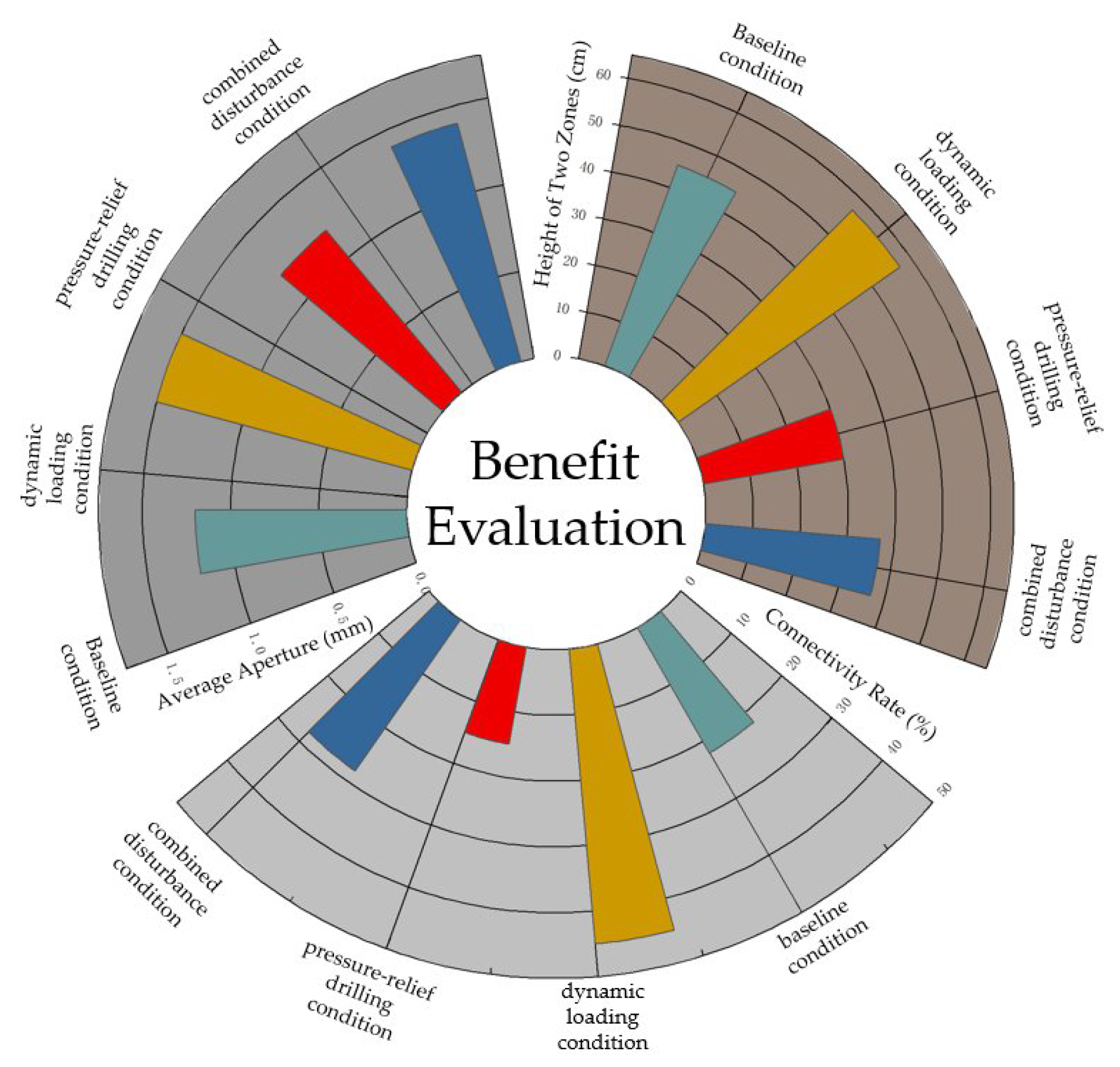
4.3. Evaluation of Dynamic Load Prevention and Control Effectiveness

Based on the above mechanistic understanding, roof pre-splitting technology provides significant prevention and control benefits for overburden response under dynamic disturbance through structural optimization and energy regulation. These benefits are mainly reflected in the following aspects:
(1)
Regulation of three-zone development: roof pre-splitting can effectively compress the height of the fracture zone while maintaining the necessary caving space, thereby preventing excessive upward propagation of water-conducting fractures.
(2)
Inhibition of disordered displacement-field diffusion: by introducing prefabricated weak planes, roof pre-splitting enables directional release of displacement energy, thereby avoiding local instability caused by disordered diffusion of displacement within the overburden.
(3)
Orderly restructuring of the fracture network: while preserving a certain pressure-relief effect, roof pre-splitting reconstructs the fracture network so that it is characterized more by directional pathways than by full-zone connectivity, thereby weakening the spatial continuity of the dynamic effect at its source.
In summary, under the coupled-disturbance condition, regulation by roof pre-splitting can achieve a synergistic effect of dynamic disturbance and directional stability control without completely suppressing the caving process driven by dynamic loading. As a result, the extent of the three zones, the intensity of fracture development, and displacement evolution can all be maintained within a controllable range, providing a feasible engineering approach for preventing and controlling disasters induced by dynamic loading under deep-mining conditions with strong strata behavior.
This study only verifies the feasibility of pressure-relief boreholes under laboratory conditions. Detailed design parameters and engineering recommendations need further study. See Figure 10 for details.

5. Conclusions

Dynamic loading drives violent collapse and fracture propagation in the overburden structure through instantaneous impact, significantly increasing the thickness of the caving zone and the extent of the fracture zone by 36.4% and 20.6%, respectively. Under dynamic disturbance, the risk of overburden instability increases markedly, particularly when abrupt changes in fracture aperture occur and fracture-network connectivity exceeds 40%, at which point the risk rises sharply.
Roof pre-splitting can effectively control both fracture-zone expansion and the intensity of overburden collapse. Under coupled-disturbance conditions, roof pre-splitting reduces fracture-zone thickness by 42.9% and decreases the amplitude of displacement fluctuations by 33.3%, thereby significantly improving overburden stability and effectively mitigating the adverse effects of dynamic loading.
This study proposes empirical and semi-quantitative indicators for dynamic instability tendency based on fracture parameters, providing an early-warning and prevention strategy for overburden instability induced by dynamic loading. Through structural optimization and energy regulation, roof pre-splitting achieves a synergistic effect of dynamic disturbance and targeted stability control, thereby offering an effective technical pathway for preventing and controlling overburden-related disasters in deep mining.

Author Contributions

Conceptualization, H.X. and C.W.; methodology, H.X.; validation, H.X., C.W., Z.Z. and C.J.; formal analysis, H.X. and X.L.; investigation, H.X.; resources, H.X. and C.W.; data curation, C.W. and J.C.; writing—original draft preparation, H.X., C.W., Z.Z. and C.J.; writing—review and editing, H.X., C.W., X.L. and J.C.; supervision, C.W., X.L. and J.C.; project administration, H.X., X.L. and J.C.; funding acquisition, H.X., X.L. and J.C. All authors have read and agreed to the published version of the manuscript.

Funding

This study was financially supported by the Excellent Young Scientists Fund of the National Natural Science Foundation of China for the project “Impact Dynamics of Mining-Induced Strata Movement in Western Coalfields” (No. 52422404), and by the Deep Earth National Science and Technology Major Project for the sub-task “Identification of the Coupling Mechanisms of Stress Field, Fracture Field, and Seepage Field in Fluidized Mining-Disturbed Rock Mass” (No. 2024ZD1004503-03).

Institutional Review Board Statement

Not applicable.

Informed Consent Statement

Not applicable.

Data Availability Statement

The original contributions presented in this study are included in the article. Further inquiries can be directed to the corresponding author.

Conflicts of Interest

Author Haidong Xu was employed by the company Maiduoshan Coal Mine of Ningxia Coal Co., Ltd., National Energy Group, now employed by the company Yangchangwan Coal Mine of Ningxia Coal Co., Ltd., National Energy Group. The remaining authors declare that the research was conducted in the absence of any commercial or financial relationships that could be construed as a potential conflict of interest.

References

  1. Qian, M.G.; Xu, J.L. Behaviors of strata movement in coal mining. J. China Coal Soc. 2019, 44, 973–984. [Google Scholar] [CrossRef]
  2. Xu, H.C.; Li, K.; Lai, X.P.; Shan, P.F.; Zhang, B.; Dai, L.P.; Yang, S.T.; Guo, Q.F.; Xi, X.; Yan, Z.M. Intelligent prediction method of rockburst driven by microseismic temporal features in deep near-vertical coal seams. Int. J. Miner. Metall. Mater. 2026. [Google Scholar] [CrossRef]
  3. Fan, W.Z.; Han, L.J. Overburden Behavior and Coal Wall Spalling Characteristics Under Large-Mining-Height Conditions. Appl. Sci. 2025, 15, 12303. [Google Scholar] [CrossRef]
  4. Liu, Y.; Zhu, Q.J.; Wei, Q.D.; Yang, G.Y.; Zhang, Y.C.; Hao, Q.L.; Jiang, D.S. Theoretical framework and reliability verification of the loaded three-zone structural model in coal mine overburden strata. Sci. Rep. 2025, 15, 35359. [Google Scholar] [CrossRef] [PubMed]
  5. Zhou, Y.; Yu, X.Y. Study of the Evolution of Water-Conducting Fracture Zones in Overlying Rock of a Fully Mechanized Caving Face in Gently Inclined Extra-Thick Coal Seams. Appl. Sci. 2022, 12, 9057. [Google Scholar] [CrossRef]
  6. Wang, W.; Pan, Y.S.; Zhao, H.R.; Xiao, Y.H.; Li, X.L.; Bao, X.Y.; Liu, Y.; Wang, J.M. Electric charge induction monitoring of deformation and failure behavior of igneous rock: Laboratory test and field application. J. Rock Mech. Geotech. Eng. 2025, 18, 861–886. [Google Scholar] [CrossRef]
  7. Fu, X.; Zeng, L.J.; Rong, H.; Zhang, H.W.; Liu, T.H.; Song, J.K. Structural model of hard overburden shell in thick coal seam and its application. Sci. Rep. 2025, 16, 2263. [Google Scholar] [CrossRef]
  8. Zhang, S.; Sun, Y.; Cao, J.T.; Lai, X.P.; Wu, L.Q. Research and optimization on the strength recovery mechanism of post peak fragmentation grouting reinforcement in mining rock mass. Front. Mater. 2025, 12, 1612050. [Google Scholar] [CrossRef]
  9. Zhang, S.; Lai, X.P.; Cao, J.T.; Xu, H.C.; Zhang, Y.; Yan, B.X.; Ji, S.T. Theoretical analyses of surrounding rock stress of a non-circular tunnel considering the horizontal inclination of initial principal stress field. Tunn. Undergr. Space Technol. 2026, 167, 106994. [Google Scholar] [CrossRef]
  10. Lai, X.P.; Zhang, S.; Cao, J.T.; Sun, Y.; Xin, F.L. Difference of “whole-process and stages” response law of energy evolution regulated by high energy storage rock modification. Geohazard Mech. 2025, 3, 99–108. [Google Scholar] [CrossRef]
  11. Tian, X.; Lan, M.; Dang, Y.C.; Li, N. An Intelligent Framework for Shear Capacity Prediction in Productive Building Structures Based on Image Reconstruction and Deep Learning Data Completion. Buildings 2026, 16, 336. [Google Scholar] [CrossRef]
  12. Jiang, Y.Z. Discussion on the Prevention of Coal Seam Roof Water Damage in the 11th Mining Area of Maiduoshan Coal Mine. Shenhua Sci. Technol. 2016, 14, 31–33. [Google Scholar]
  13. Lan, T.W.; Zhang, Z.J.; Guo, W.Q.; Li, Z.; Wu, G.Q.; Fang, P. Study on the linkage mechanism between key strata fracture in overburden and surface subsidence during caving mining in extra-thick coal seams. Sci. Rep. 2025, 15, 2256. [Google Scholar] [CrossRef]
  14. Fu, L.L.; Zhang, G.J.; Ma, Y.T.; Xing, L.Y.; Guo, G.L.; Sui, J.C.; Gao, X.; Li, H.Z.; Li, C.J.; Guan, R.F. Research on the strata movement laws of deep multi-seam mining in super-thick and weak cementation overburden. KSCE J. Civ. Eng. 2026, 30, 100469. [Google Scholar] [CrossRef]
  15. He, Y.F.; Zhang, J.; Liu, H.; Yang, T.; Sun, J.P. Study on Activation and Restructuring of Key Strata in Shallowly Buried Coal Seam Bearing Structure and Load Characteristics. Processes 2024, 12, 1257. [Google Scholar] [CrossRef]
  16. Teng, T.; Xu, Z.H.; Wang, Y.X. Overburden Damage in High-Intensity Mining: Effects of Lithology and Formation Structure. Appl. Sci. 2025, 15, 10518. [Google Scholar] [CrossRef]
  17. Yuan, Q.; Chai, J.; Zhang, Y.Z.; Liu, Y.L.; Ren, Y.W. Investigation of Deformation Pattern and Movement Law of the Huge-Thick Conglomerate Stratum by a Large-Scale 3D Model Test with Distributed Optical Fiber Sensor Monitoring. Sensors 2021, 21, 5985. [Google Scholar] [CrossRef]
  18. Wang, X.Z.; Xie, J.L.; Zhu, W.B.; Xu, J.L. The field monitoring experiment of the high-level key stratum movement in coal mining based on collaborative DOFS and MPBX. Sci. Rep. 2022, 12, 665. [Google Scholar] [CrossRef]
  19. Cheng, G.W.; Yang, T.H.; Liu, H.Y.; Wei, L.K.; Zhao, Y.; Liu, Y.L.; Qian, J.W. Characteristics of stratum movement induced by downward longwall mining activities in middle-distance multi-seam. Int. J. Rock Mech. Min. Sci. 2020, 136, 104517. [Google Scholar] [CrossRef]
  20. Deng, G.D.; Xie, H.P.; Gao, M.Z.; Xie, J.; Li, C.; He, Z.Q. Fracture Mechanisms of Competent Overburden Under High Stress Conditions: A Case Study. Rock Mech. Rock Eng. 2022, 56, 1759–1777. [Google Scholar] [CrossRef]
  21. Cheng, G.; Xu, W.T.; Shi, B.; Wu, J.H.; Sun, B.Y.; Zhu, H.H.; Li, J.Z. Experimental study on the deformation and failure mechanism of overburden rock during coal mining using a comprehensive intelligent sensing method. J. Rock Mech. Geotech. Eng. 2022, 14, 1626–1641. [Google Scholar] [CrossRef]
  22. Xu, H.C.; Li, K.; Shan, P.F.; Wu, X.F.; Zhang, S. Automatic Picking Method for the First Arrival Time of Microseismic Signals Based on Fractal Theory and Feature Fusion. Fractal Fract. 2025, 9, 679. [Google Scholar] [CrossRef]
  23. Zhang, Z.Z.; Gao, F.; Shang, X.J. Rock burst proneness prediction by acoustic emission test during rock deformation. J. Cent. South Univ. 2014, 21, 373–380. [Google Scholar] [CrossRef]
  24. Wang, Z.K.; Li, W.P.; Wang, Q.Q.; Hu, Y.B.; Du, J.F. Monitoring the Dynamic Response of the Overlying Rock–Soil Composite Structure to Underground Mining Using BOTDR and FBG Sensing Technologies. Rock Mech. Rock Eng. 2021, 54, 5095–5116. [Google Scholar] [CrossRef]
  25. LI, R.; Li, X.B.; Wang, B.C.; Liu, X.X.; Li, Y.K. Comparison of Commonly Used Methods in Mine Water Inflow Prediction—A Case Study of Maiduoshan Coalmine Winning District No.11 Hydrogeological Complementary Exploration in Yuanyanghu Mining Area, Ningdong Coalfield, Ningxia. Coal Geol. China 2014, 26, 30–33+38. [Google Scholar] [CrossRef]
  26. Ma, Y.; Wu, Q.Y.; Yang, J.H.; Gao, F.Q.; Lou, J.F.; He, B.W.; Li, J.Z. Study on the effect of mining height on overburden strata movement in longwall mining. Int. J. Coal Sci. Technol. 2025, 12, 59. [Google Scholar] [CrossRef]
  27. Qian, M.G.; Miao, X.X.; Xu, J.L. Research on Key Layer Theory in Rock Control. J. China Coal Soc. 1996, 2–7. [Google Scholar] [CrossRef]
  28. Ti, Z.Y.; Li, J.Z.; Wang, M.; Li, X.Y.; Jin, Z.P. Fracture Characteristics and Zoning Model of Overburden during Longwall Mining. Shock. Vib. 2021, 2021, 2857750. [Google Scholar] [CrossRef]
  29. Li, Y.L.; Gan, J.N.; Zhang, G.J.; Liu, Z.Y.; Guo, G.L.; Guo, B.D.; Sun, S. Research on Strata Movement Control in Deep Composite Lithologic Gangue Backfill Mining of Super-Thick and Weak Cementation Overburden Based on PFC–FLAC Coupling Simulation. Adv. Civ. Eng. 2025, 2025, 6650989. [Google Scholar] [CrossRef]
  30. Wang, K.; Li, J.Z.; Jin, Z.P. Influence of the Primary Key Stratum on Surface Subsidence during Longwall Mining. Sustainability 2022, 14, 15027. [Google Scholar] [CrossRef]
Figure 1. Integrated stratigraphic column chart for 11N0201 working face.
Applsci 16 06532 g001
Figure 2. Experimental monitoring equipment. The figure consists of two parts: (i) a total station monitoring system, (ii) a borehole imaging system.
Applsci 16 06532 g002
Figure 3. Layout of the physical similarity simulation model.
Applsci 16 06532 g003
Figure 4. Overburden collapse characteristics under the baseline condition. The figure consists of seven parts: (i) elastic bending, (ii) initial collapse of the immediate roof, (iii) initial weighting of the main roof, (iv) complete collapse of the main roof, (v) fracture of the sub-key stratum, (vi) periodic collapse, and (vii) stable stage.
Applsci 16 06532 g004
Figure 5. Borehole observation maps at different depths under the baseline condition. The figure consists of three parts: (i) initial state, (ii) critical state, and (iii) complete mining state.
Applsci 16 06532 g005
Figure 6. Displacement-monitoring analysis under the baseline condition. The figure consists of three parts: (i) initial weighting measurement point coordinates and displacement contour map, (ii) periodic weighting measurement point coordinates and displacement contour map, and (iii) end of mining measurement point coordinates and displacement contour map.
Applsci 16 06532 g006
Figure 7. Overburden collapse characteristics under the dynamic-loading condition. The figure consists of six parts: (i) initial collapse of the immediate roof, (ii) initial weighting of the main roof, (iii) formation of the “Cantilever Beam”, (iv) complete collapse of the main roof, (v) periodic collapse, and (vi) stable stage.
Applsci 16 06532 g007
Figure 8. Borehole observation maps at different depths under the dynamic-loading condition. The figure consists of three parts: (i) initial state, (ii) critical state, and (iii) complete mining state.
Applsci 16 06532 g008
Figure 9. Displacement-monitoring analysis under the dynamic-loading condition. The figure consists of three parts: (i) initial weighting measurement point coordinates and displacement contour map, (ii) periodic weighting measurement point coordinates and displacement contour map, and (iii) end of mining measurement point coordinates and displacement contour map.
Applsci 16 06532 g009
Figure 10. Analysis chart of benefit evaluation of dynamic load prevention and control. The figure consists of three parts: (i) data of the two-zone thickness under the four working conditions, (ii) data of fracture connectivity under the four working conditions, and (iii) data of average fracture aperture under the four working conditions.
Applsci 16 06532 g010
Table 1. Mechanical parameters of representative coal and rock strata.
No.LithologyModel Thickness (cm)Material Consumption (kg)Unit Weight γ (kN/m3)Elastic Modulus E (GPa)Tensile Strength σ t (MPa)Protodyakonov Hardness Coefficient f
River SandGypsumCalcium CarbonateCoal Powder
16Fine-grained Sandstone6281.62.4 24.8152.86.01
17Coarse-grained Sandstone1521.330.81.87 25.5253.54.72
18Fine-grained Sandstone5140.81.2 24.8152.86.01
19Coarse-grained Sandstone1021.330.81.87 25.3223.34.72
20Coal 1150.251.25 14.52.50.82~3
21Siltstone114.220.711.07 24.5102.05.59
22Medium-coarse-grained Sandstone4140.61.4 25.0203.05.68
23Siltstone214.220.711.07 24.5102.05.59
24Coal 23150.753.75 14.52.50.82~3
Table 2. Empirical formulas for determining the heights of the three zones.
Three ZonesEmpirical FormulasCalculated Height (Baseline)
Caving Zone H m = 100 M 4.7 M + 19 ± 2.2 6.86~11.26 cm
Fracture Zone H 1 = 100 M 1.6 M + 3.6 ± 5.6 30.11~41.31 cm
Bending Subsidence Zone H 3 = H H m H 1 68.74~83.14 cm
Table 3. Comparison of key parameters of the overburden “three zones” under different working conditions.
Test CaseCaving Zone Thickness (cm)Fractured Zone Thickness (cm)Calculated Caving Zone Thickness (cm)Calculated Fractured Zone Thickness (cm)Continuous Bending Subsidence Zone Thickness (cm)Fracture Angle (°)Deflection Angle (°)
I11346.86~11.2630.11~41.31756356
II1542 635942
III1018 925452
IV1324 836554
Table 4. Comparative analysis of displacement data under different working conditions.
Displacement IndicatorsScenario 1 (Baseline Condition)Scenario 2 (Dynamic Loading Condition)Scenario 3 (Roof Pre-Splitting Condition)Scenario 4 (Combined Disturbance Condition)
Maximum Vertical Displacement During Initial Weighting (cm)2.16 (Measurement points A3–A6)1.20 (Measurement points A9–A10)2.50 (Measurement point A17)3.00 (Measurement point A26)
Maximum Vertical Displacement During Periodic Weighting (cm)2.16 (Measurement points Row A)0.30 (Measurement points Row B)2.30 (Measurement point B18)3.50 (Measurement point A29)
Maximum Vertical Displacement at the End of Mining (cm)0.30 (Measurement points B3–B4)0.30 (Measurement points Row D)2.80 (Measurement point A24)3.50 (Measurement points A29–A30)
Displacement Fluctuation Amplitude Across the Entire Stage (cm)<0.051.20.5<0.8
Area Proportion of High Displacement Zone (At the End of Mining Stage, %)61879
Table 5. Comparative analysis of fracture-development characteristics under different working conditions.
Evolution StageScenario 1 (Baseline Condition)Scenario 2 (Dynamic Loading Condition)Scenario 3 (Roof Pre-Splitting Condition)Scenario 4 (Combined Disturbance Condition)
Initial stageSparse primary fractures; no obvious stress concentration; fracture density: 4.1 fractures/mSimilar to Case 1; fracture density: 4.0 fractures/mUniformly distributed fractures; no obvious stress concentration; fracture density: 4.2 fractures/mUniformly distributed fractures; no obvious stress concentration; fracture density: 4.1 fractures/m
Critical development stageFracture proportion: 30%; pronounced directional propagation; fracture density: 7.3 fractures/mFracture proportion: 60%; dispersed strike orientation; accompanied by secondary fractures; fracture density: 9.8 fractures/mFracture proportion: 20%; feather-like distribution; concentrated strike orientation; fracture density: 6.8 fractures/mFracture proportion: 40%; concentrated strike orientation; accelerated initiation; fracture density: 8.5 fractures/m
Final mining stageBedding-parallel through-going fractures without cross-cutting; connectivity: 22%; fracture density: 10.5 fractures/m; average aperture: 1.2 mm; upper limit extends to the lower part of the main key stratumCross-cutting and through-going fractures; connectivity: 45%; fracture density: 12.2 fractures/m; average aperture: 1.5 mm; upper limit extends to 82 m in the prototype; abrupt aperture increase observedFractures directionally connected along pressure-relief boreholes; connectivity: 15%; fracture density: 10.0 fractures/m; average aperture: 1.2 mm; upper limit extends to 50 m in the prototypeDirectionally connected fractures without cross-cutting; connectivity: 28%; fracture density: 11.5 fractures/m; average aperture: 1.4 mm; upper limit extends to 62 m in the prototype
Disclaimer/Publisher’s Note: The statements, opinions and data contained in all publications are solely those of the individual author(s) and contributor(s) and not of MDPI and/or the editor(s). MDPI and/or the editor(s) disclaim responsibility for any injury to people or property resulting from any ideas, methods, instructions or products referred to in the content.