1. Introduction
Operators of construction machinery and other vehicles are subjected to vertical vibration induced by uneven road surfaces, floor excitation, and machinery operation [
1]. The seat suspension constitutes the principal transmission path between the floor and the driver; therefore, it is expected to attenuate vibration while maintaining ride comfort. In many vehicle applications, this task is performed by passive seat suspensions, in which damping and mechanical friction dissipate vibration energy. Owing to their fixed mechanical parameters, passive structures have limited adaptability, and their isolation performance may deteriorate markedly in the resonance region [
2].
Motivated by the limitations of passive systems, semi-active and active seat suspensions have received substantial research attention. Semi-active configurations often use electrorheological or magnetorheological materials to adjust damping or stiffness with relatively low energy consumption and favorable fail-safe characteristics [
3,
4]. Active configurations employ actuators to generate controllable forces and generally provide greater vibration-isolation capability [
5]. Given the similarity between seat-suspension and vehicle-suspension vertical dynamics, control strategies developed for vehicle suspensions are also relevant to seat applications. Reported active-suspension controllers include H-infinity control [
6,
7,
8,
9,
10], adaptive backstepping control [
11,
12,
13,
14,
15,
16,
17,
18,
19,
20,
21], sliding mode control (SMC) [
22,
23,
24,
25], fuzzy control [
26,
27,
28], Linear–Quadratic–Gaussian (LQG) control [
29,
30,
31], and hybrid schemes [
32,
33,
34,
35,
36,
37,
38].
In addition to these approaches, actuator-oriented active control studies considering roll dynamics provide useful references for suspension design [
39]. Meanwhile, model predictive control (MPC) has also attracted attention because it can explicitly handle constraints and preview information; for example, speed-dependent MPC with road preview information has recently been employed to improve suspension performance under varying operating conditions [
40]. These studies further indicate that actuator configuration, preview information, and constraint-handling strategy should be jointly considered in active suspension control.
Admittedly, acceleration signals are overly sensitive to controller inputs and susceptible to high-frequency noise, which can lead to frequent actuator actuation, which is a primary reason why their use remains limited in most control designs. Nevertheless, accelerometers are low-cost and easy to deploy, directly capture ride comfort, and, when used in direct feedback, circumvent the errors and delays inherent in integrating displacement and velocity. Recent acceleration-related suspension studies have also shown that vibration characteristics can be modified without relying exclusively on displacement and velocity information [
41], and acceleration feedback has been applied in active suspension design to improve ride comfort [
42]. These advantages render acceleration feedback a promising avenue for further research.
Parameter uncertainty constitutes another central challenge in suspension control. In seat applications, the sprung mass varies among drivers, whereas the effective stiffness and damping of the suspension may be influenced by temperature, wear, fatigue, and other operating conditions [
13]. Adaptive strategies are therefore commonly introduced to preserve control performance under parameter variations. For example, adaptive laws combined with backstepping or SMC have been used to address uncertain suspension parameters [
12,
13,
14,
15,
16,
17,
18,
19,
20,
21]. Neural-network estimators have also been adopted to approximate mass and suspension characteristics in [
32,
33,
35]. Other studies employ Takagi–Sugeno (T-S) fuzzy modeling, dynamic SMC, or approximation-free control to handle uncertainties without explicit parameter estimators [
32,
37,
38].
The actuator model is also a determinant of the achievable control performance. In several related studies, including [
11,
12,
32], the actuator output force is represented by a proportional relation with the control command. Practical hydraulic or electromagnetic actuators, however, may exhibit saturation, hysteresis, gain uncertainty, and other nonlinear behavior. These non-ideal effects have been treated through different modeling and control strategies. The uncertain control gain has been handled through H-infinity design in [
7,
11,
34]; a unified model including dead-zone and hysteresis was developed in [
13]; saturation has been formulated with an auxiliary design system in [
16,
33]; and adaptive SMC was used in [
22] to compensate for unknown control gain. Delay-aware H-infinity control has also been reported, although it generally requires prior knowledge of the delay parameters, which reduces practical applicability. In the present study, the output feedback problem is converted into a state-feedback problem by selecting suitable system variables.
Although H-infinity control, LMI synthesis, and adaptive or variable weighting strategies have been separately established in suspension control, the present work does not claim a fundamentally new general control theory. Its originality lies in a problem-oriented formulation for acceleration-feedback active seat-suspension control, in which the high-sensitivity acceleration signal, deformation-dependent safety requirement, time-delayed actuation, and actuator-force limitation are handled in one synthesis procedure. Specifically: (1) an acceleration-feedback-oriented auxiliary virtual state variable is formulated so that the comfort objective and the suspension deformation objective are coupled through a deformation-dependent weighting law rather than through a fixed trade-off; (2) the resulting time-varying weighting terms are embedded into an augmented system and converted into LMI conditions, which makes the method directly implementable with state feedback under input delay; (3) actuator saturation and the deformation-dependent motor-to-vertical-force gain are treated through conservative input constraints; and (4) numerical simulations and laboratory prototype experiments are used to evaluate feasibility, limitations, and the remaining gap before field application.
The present study is positioned as a laboratory prototype investigation of active seat-suspension control. Since measured field excitation data from a specific engineering application are not used, the experimental results should be interpreted as laboratory feasibility evidence rather than field validation. Field-data-based validation is identified as a necessary next step.
The rest of this paper is arranged as follows. In
Section 2, the system model of the controlled driver-seat system is established, and the control problem is formulated. In
Section 3, the auxiliary virtual state variable is presented, and the controller is synthesized using an LMI approach. In
Section 4, the performance of the closed-loop (CL) system is examined through numerical simulation and experimental validation. Finally, the conclusion and suggestions for future work are given at the end of this paper.
2. System Modeling and Problem Formulation
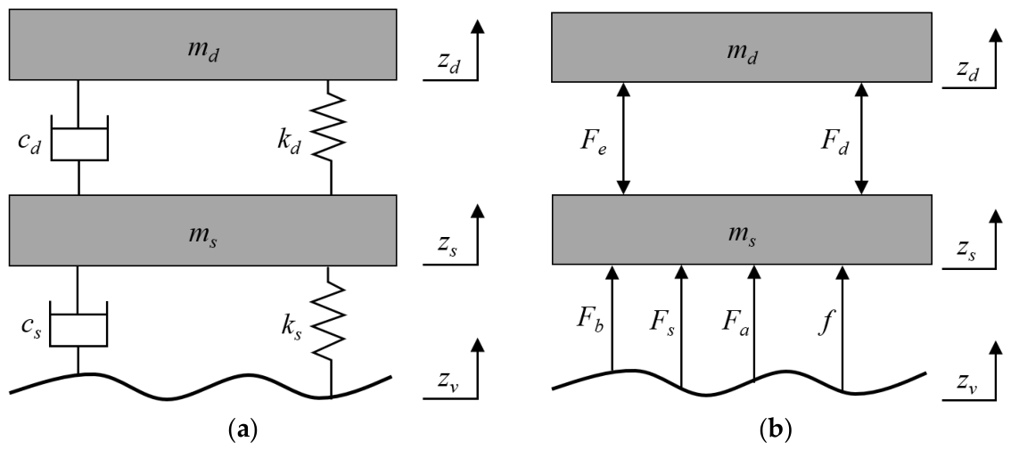
To make the controller synthesis tractable while retaining the dominant vertical vibration behavior considered in this study, the driver-seat system is represented by a 2-DOF model, as shown in
Figure 1a. The stiffness and damping elements are described by their coefficients, whereas
Figure 1b gives the corresponding free-body diagram used to define the interaction forces in the dynamic equations. This modeling choice mainly targets the low-frequency vertical vibration range relevant to seat-suspension comfort, and higher-order structural dynamics of a specific vehicle or machinery cabin are not explicitly included.
In the adopted model, the driver and seat are represented as two lumped bodies. Based on the free-body diagram in
Figure 1b, the corresponding 2-DOF dynamic equations are established from the force equilibrium of the two masses:
where
and
are the masses of the driver and seat, respectively.
and
denote the stiffness and damping coefficients between the driver and seat, while
and
denote the equivalent stiffness and damping coefficients of the seat suspension.
and
are the elastic and damping forces between driver and seat, respectively.
,
and
are the elastic, damping, and friction forces of seat suspension, respectively.
is the actuating force.
Under the assumption of a relatively small seat mass and limited driver-seat relative displacement within the considered vibration range, the driver and seat are combined into one equivalent body for controller design. The control objective is mainly associated with ride comfort and suspension stroke, whereas the absolute vertical displacement of the seat is not used as the primary controlled quantity. Accordingly, summing the two equations in Equation (1) and redefining the state variable leads to the following single-DOF representation:
The subsequent reduction to a single-DOF model is therefore an engineering simplification for control design rather than an exhaustive biomechanical representation. The possible high-frequency relative motion between the human body and the seat is neglected in the present controller synthesis.
where
is the integrated mass.
and
are the linearized stiffness and damping coefficients, respectively.
is the lumped disturbance term. It is worth noting that, in Equation (2), the suspension deformation
and its time derivative
can be observed easily, which will greatly facilitate the development of the control strategy. Considering the control delay existing in the actuator, the active force
can be expressed as a time-delayed function of the input signal
:
The linearized coefficients
and
are used in the nominal model for LMI-based controller synthesis. In the practical prototype, stiffness, damping, Coulomb friction, and hysteresis may exhibit nonlinear characteristics and may vary with suspension height, temperature, wear, and operating conditions. In this study, the parameter-perturbation simulation directly examines variations in the driver mass, seat-suspension stiffness, and damping coefficient. The friction and hysteresis effects are represented as bounded uncertainties based on the identified nonlinear friction–damping model and are indirectly involved in the prototype experiments, rather than being independently validated under all possible operating conditions.
where
is the control gain.
denotes the time-varying total actuation delay, and
is its known upper bound, i.e.,
.
In practice, should be selected as a conservative upper bound of the total actuation delay, including controller computation, signal conversion, communication, servo-drive response, and mechanical actuation lag. It can be determined from actuator step-response tests or timing measurements of the control loop, and the LMI conditions are solved using this worst-case bound to preserve stability under all admissible delays.
The active seat suspension aims to minimize the vertical acceleration. However, it is well known that there exists an inherent conflict between the ride comfort, active force, and suspension deformation. For a given road excitation, greater comfort tends to demand larger suspension deformation and higher demand for actuating forces, potentially leading to end-stop impacts and actuator saturation. Furthermore, for safety considerations, the physical limits of the suspension structure and actuator saturation must also be accounted for.
The control input is therefore synthesized to satisfy the following requirements:
(1) The closed-loop (CL) system maintains asymptotic stability, and the trade-off between suspension deflection and ride comfort is adjusted dynamically.
(2) The suspension stroke remains within the allowable travel of the mechanical structure:
where
is the corresponding structural limit.
(3) The required active force remains within the actuator capacity:
where
is the maximum actuating force.
It is worth noting that the equivalent control gain varies with the suspension deformation. To facilitate the controller design, the maximum envelope value of the control gain, denoted as , is adopted here. Consequently, the actuator saturation constraint is conservatively converted into a constraint on the control input signal: .
This envelope-based treatment is adopted to provide a safety-oriented input constraint for controller synthesis. By using the maximum value of the deformation-dependent actuator gain, the commanded control input can be kept within the allowable actuation-force range under the considered gain variation. It should be noted that detailed actuator nonlinearities, such as hysteresis, dead-zone, and saturation dynamics, are not explicitly embedded in the present controller and will be further investigated in future work.
3. Controller Synthesis
This section develops the controller synthesis procedure based on the model and constraints formulated in
Section 2. First, an augmented system is constructed by introducing an auxiliary virtual state and deformation-dependent weighting functions, so that ride comfort and suspension-stroke safety can be incorporated into a unified control objective. Then, a state-feedback H-infinity controller is synthesized through LMI conditions while considering input delay, parameter uncertainty, and actuation constraints. The resulting controller provides the theoretical basis for the numerical and experimental evaluations in
Section 4.
3.1. Augmented System Design
The key design issue is the conflict between ride-comfort improvement and suspension-stroke safety. When suspension deformation is small, the controller should emphasize acceleration attenuation; when deformation approaches the allowable stroke boundary, the comfort objective should be relaxed so that end-stop impact can be avoided. In addition, because acceleration is directly measurable but noise-sensitive, it should be introduced through a weighted objective rather than treated as an unconstrained aggressive feedback signal.
Motivated by the above discussion, the following cost function is selected as the overall control objective:
where
and
are two dynamic low-pass filters, given as follows:
where
is the Laplace calculator,
is the cut-off frequency, and
,
,
and
are positive design parameters.
is a nonlinear function for coordinating the trade-off between ride comfort and suspension deformation. When suspension deformation is small, the weight
is appropriately increased, and the passband widened, thereby steering the controller to prioritize driver comfort; when suspension deformation becomes large, greater emphasis is placed on controlling the amount of deformation to prevent impact caused by the suspension hitting the end stops. The nonlinear function
can be designed as follows:
where
and
are two design parameters satisfying
and
. It is easy to verify that
fulfills
.
Recalling Equation (6), one can easily obtain the time derivative of
.
By treating
as a virtual state variable and adding it to the governing Equation (2), an augmented system with time-varying matrices
,
,
and delay
in the state is created. Thus, the state variable vector of the augmented system is obtained as
. Combining Equations (2) and (9), the augmented dynamic equations can be expressed in the matrix form:
with
where
and
.
Note that matrices
,
and
will vary with the suspension deformation. These matrices are rewritten in the following form:
where
Therefore, our objective is to design a proper controller to minimize the controlled output , and guarantee that and will not exceed the corresponding physical limits.
3.2. State-Feedback H-Infinity Control
In this section, a state-feedback H-infinity controller will be synthesized by using the LMI method. The following lemma will be used in later development.
Lemma 1. Given matrices X and Y of appropriate dimensions [43], we havewhere is an arbitrary proof. Then, the main result of this paper is presented as the following theorem: Theorem 1. Given scalars , , , and , if there exist matrices , , and of appropriate dimensions such that the following LMIs hold:where donates a identity matrix. Then, (1) the CL system described in Equations (10) and (11) is asymptotically stable with H-infinity performance for the delay ; (2) the maximum actuator-force constraint in Equation (5) is satisfied with the disturbance energy under the bound .
Proof. Considering the following Lyapunov–Krasovskii function:
Taking the time derivative of
gives
According to the Newton–Leibniz formula, for any appropriately dimensioned matrix
, the following equality is established:
where
. Adding Equation (20) to Equation (19), the following inequality can be obtained:
Adding
to both sides of the above inequality and after some simple calculations, this yields
where
Note that the time-varying matrices
,
and
are included in
and
. By substituting Equation (12) into
and
, it follows that
where
,
and
. Substituting Equations (24) and (25) into inequality (22), and noting that
is positive because
is positive, and
, the following inequality can be obtained:
Let
be the right-hand side of (26); then, given a pair of
and
, the following inequality can be derived by noting
and employing Lemma 1.
On the other hand, by the Schur complement, inequality (15) guarantees that
Noting that
,
,
,
and
, it can be concluded that
is negative and thus, the following inequality holds:
Therefore, the CL system is asymptotically stable in the presence of control delay, and the H-infinity performance is guaranteed.
Inequality (29) guarantees that
. Integrating both sides of this inequality from zero to any
, this gives
Noting that the second term of the Lyapunov function (18) is positive, we obtain
, with
. Consider the following inequalities:
where
denotes the maximal eigenvalue of the matrix. By employing the Schur complement and combing the above inequalities with inequality (16), one can prove that the physical constraints (4) and (5) are guaranteed. This is the end of the proof.
Define , and . Pre- and post-multiplying (15) and (16) with , , and their transposes, respectively, together with the change in matrix variables defined by , , , , we obtain the following result by noting that . □
Theorem 2. Consider the controlled driver-seat system in (10) with actuation time delay, given scalars , , , and , if there exist symmetric matrices , , and matrices , satisfyingwhere Then, a state-feedback controller exists, such that (1) the CL system is asymptotically stable with H-infinity performance ; (2) the maximum actuator-force constraint in Equation (5) is satisfied with the disturbance energy under the bound .
The control gain matrix is obtained as Remark 1. It should also be noted that the LMI-based synthesis gives a sufficient rather than necessary stability condition. Therefore, the obtained controller may be conservative, especially when a large delay bound or uncertainty range is selected. In this work, such conservatism is accepted to prioritize closed-loop stability and physical safety constraints over aggressive vibration suppression.
4. Control Algorithm Evaluation
In this section, the feasibility, robustness, and limitations of the proposed controller are evaluated through both numerical simulation and laboratory prototype validation. Furthermore, to evaluate the robustness of the proposed controller to system parameter perturbation, the driver mass is decreased by 20%, the stiffness of seat suspension is increased by 20% and the damping coefficient is increased by 30%; i.e., md = 52 kg, ks = 5400 N·m−1, and cs = 554 N·s·m−1. Other parameters remain unchanged.
To clarify the connection between the theoretical design, numerical simulation, and experimental validation, the evaluation in this section is organized as follows. The LMI-based analysis in
Section 3 provides stability and constraint-satisfaction conditions under the stated model assumptions. The numerical simulation then implements the same driver-seat model and introduces parameter perturbations to examine the controller response under controlled uncertainty. Finally, the laboratory prototype experiment evaluates whether the expected vibration attenuation can be observed in the physical seat suspension. Therefore, the simulation is used to examine the theoretical model under repeatable conditions, whereas the experiment provides practical performance evidence rather than a direct proof of all LMI conditions.
4.1. Numerical Simulation
The 2-DOF driver-seat model shown in
Figure 1 is employed for the simulation. The physical parameter values of this model are given in
Table 1. The uncontrolled case, in which a viscous damper of 600 N·s·m
−1 is used to replace the actuating mechanism, is simulated for comparison. In order to achieve a fast convergence rate, the PPF of the controller is set to be relatively aggressive:
. Other control parameters are designed as
,
. It should be pointed out that an ideal actuator is assumed in the numerical simulation. However, considering the limited bandwidth of a practical actuator, a low-pass filter is added between the control signal and the actuator.
The parameters listed in
Table 1 are treated as nominal parameters of the tested driver-seat prototype. The mass terms are determined from the experimental configuration, while the equivalent stiffness, damping, Coulomb friction, and hysteresis-related parameters are obtained from component characterization and the identification procedure described in
Section 4.2. These values are used to establish a representative simulation model for controller evaluation, rather than a universal parameter set for all seat-suspension applications.
4.2. Nonlinear Active Seat Suspension
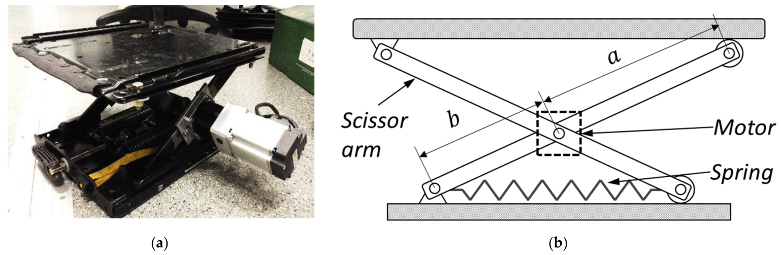
An active seat-suspension prototype is built based on a modification of a normal passive seat suspension for heavy-duty vehicles, as shown in
Figure 2a. The seat is supported by a pair of scissor mechanisms. An actuator is installed at the center of the left-side scissor structure, comprising a servo motor and a reduction gear.
Figure 2b illustrates the mechanical layout for generating the vertical active force. In this arrangement, the motor torque is transmitted through the scissor mechanism and is expressed as
where
is the length of the scissor arm.
is the suspension height.
is the ratio of the reduction gear.
As the internal servo-motor control law is outside the scope of the present study, the mapping from the command signal to the active torque is described by an approximate linear relation:
where
is the control input signal,
is the linearized control gain, and
is the error of linearization.
Substitution of Equation (37) into Equation (36) yields the relationship between the equivalent vertical active force and the command signal:
where
is the equivalent control gain from control signal to vertical active force, which will change with the variation in the suspension deformation.
is an equivalent disturbance term.
The linear input-force relation in Equations (37)–(39) is adopted as a nominal approximation for controller implementation. Nonlinearities of the servo drive and reduction gear, including small hysteresis and gain errors, are included in
or
and are not explicitly compensated by a dedicated actuator model in the current study.
In order to achieve better control performance, the original damper is removed, and the vertical stiffness is provided by a horizontally installed spring and the scissor mechanism. According to the geometry shown in
Figure 2b, the vertical elastic force is calculated as
where
is the elastic force of the spring with
as the spring rate, and
is the suspension height in the equilibrium position.
Differentiation of the elastic-force expression with respect to the suspension height gives the equivalent vertical stiffness:
Equation (41) indicates the dependence of the equivalent vertical stiffness on the suspension height. Under small-amplitude vibration, this stiffness is evaluated by linearizing the expression around the equilibrium position.
The seat-suspension mechanism is also affected by friction, which is mainly associated with dry contact between metallic components. The Coulomb friction model is therefore adopted:
where
is the Coulomb friction force and
is the deformation rate of the seat suspension.
The reduction gear further introduces an additional damping effect. In contrast to the dry-friction component, this damping exhibits clear hysteresis and is described by the extended Bouc–Wen differential model [
44,
45]:
where
and
are the non-hysteresis and hysteresis coefficients, respectively.
is an auxiliary variable with
, and
,
and
are the non-dimensional parameters that determine the shape and amplitude of the hysteresis loop.
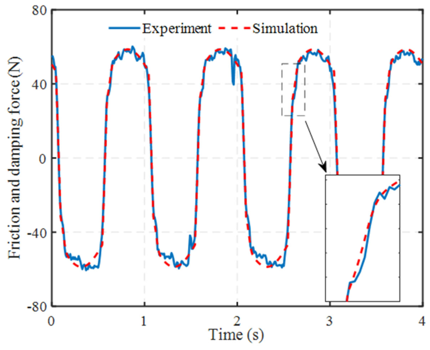
Figure 3 reports the experimental validation and parameter identification results for the friction–damping model.
As depicted in
Figure 3, the experimentally measured dynamic responses of the friction and damping forces exhibit striking agreement with the simulated trajectories derived from the extended Bouc–Wen differential model. Notably, even within the localized, highly nonlinear hysteresis regions characteristic of force reversals, the computational model accurately captures and reproduces the transient dynamic behavior of the physical system. This robust alignment effectively validates the fidelity of the proposed nonlinear friction–damping mathematical formulation, providing a rigorous empirical basis for subsequent control synthesis. Predicated on this validation, the inherently complex Bouc–Wen differential equations are strategically simplified, reformulating the dynamics into an equivalent linear damping coefficient coupled with a hysteresis-induced bounded disturbance term. Given that real-world friction and damping parameters are notoriously difficult to quantify precisely and are highly susceptible to drastic fluctuations driven by operating conditions, material fatigue, or aging processes, this simplification framework effectively recasts convoluted nonlinear physical resistances as bounded system uncertainties, thereby establishing the requisite theoretical foundation for designing highly robust active suspension controllers capable of adapting to complex, time-varying operational environments.
For the subsequent controller synthesis, the Bouc–Wen dynamics are converted into an equivalent simplified representation. The following Lyapunov function is selected:
Its time derivative is obtained as
According to Equation (45), the boundedness of the auxiliary variable can be inferred under the stated parameter condition. Therefore, the damping force in Equation (43) is rewritten as
where
is the equivalent linear damping coefficient, and
is the hysteresis-resultant bounded disturbance term.
The Coulomb friction, equivalent vertical stiffness, and damping coefficients can be estimated from experimental data; nevertheless, their values may deviate from the nominal results with changes in suspension deformation, operating environment, fatigue state, or aging condition. Consequently, exact parameter information is difficult to guarantee in practical implementation, and these quantities are treated as uncertainties in the controller design.
This bounded-disturbance treatment is introduced to make the robust controller synthesis tractable while preserving the dominant influence of friction and hysteresis on the seat-suspension dynamics. It does not imply exact real-time compensation of all nonlinear effects; rather, it assumes that the residual nonlinear terms remain within the uncertainty range considered in the control design.
4.3. Experimental Validation
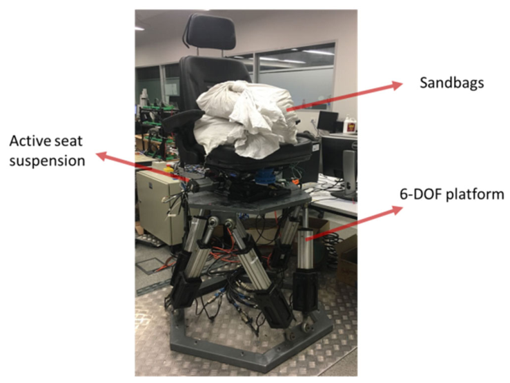
The proposed controller is implemented in the lab. The experimental setup is shown in
Figure 4. A 6-DOF vibration platform is used to generate the vertical excitation. The lower base of the seat suspension is fixed on this platform, and sandbags with an equivalent driver mass are placed on the seat to emulate the driver loading condition. The active seat suspension is controlled by an NI CompactRio 9074 (National Instruments Corporation, Austin, TX, USA) with one NI 9205 and one NI 9264 module. The control frequency is set as 500 Hz. Two displacement sensors (Micro Epsilon ILD1302-100, Micro-Epsilon Messtechnik GmbH & Co. KG, Ortenburg, Germany) are utilized to measure the vertical displacements of the vibration platform and the seat. The vertical velocity is obtained by taking the time differential of the displacement signals. Comparative experiments based on both the controlled and uncontrolled cases are carried out. The passive experiment is implemented with the passive seat suspension (GARPEN GSSC7, Garpen Pty Ltd., Perth, Australia), which is a seat with a well-tuned spring and damper for heavy-duty vehicles. Two scenarios are applied to evaluate the performance of the proposed controller in both time and frequency domains.
Because actual driver mass, posture, and biodynamic characteristics can affect seat-suspension dynamics, the experimental results should be interpreted as prototype-level feasibility evidence under the tested equivalent loading condition, rather than as a statistically generalized conclusion for all operators. Future work will include tests with multiple human subjects or equivalent anthropomorphic loads.
A dedicated comparison between the directly measured displacement and the displacement reconstructed by double integration of the acceleration signal was not conducted in the present experiment. Because acceleration double integration is sensitive to sensor bias, low-frequency drift, initial conditions, and filtering choices, it may introduce accumulated displacement errors. Therefore, the displacement sensor measurements are used as the reference for suspension deformation evaluation in this study, and a systematic comparison with acceleration-based displacement reconstruction will be considered in future work.
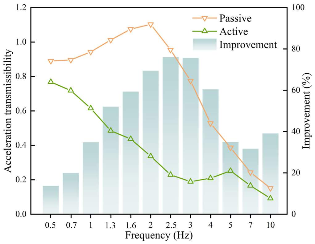
Scenario 1: The system was subjected to a series of sinusoidal excitations with frequencies sweeping from 0.5 Hz to 10 Hz to evaluate its acceleration transmissibility. Considering the maximum actuating torque of the experiment device, the prescribed performance functions (PPFs) are tuned to be relatively loose. The experimental outcomes are presented in
Figure 5.
The transmissibility reduction ratio used to quantify the improvement in
Figure 5 is defined as follows:
where
and
denote the acceleration transmissibility of the passive and active systems at frequency f, respectively.
Figure 5 illustrates the experimental acceleration transmissibility of the system across the 0.5–10 Hz frequency range. The passive suspension exhibits a resonance peak near 2 Hz, where the transmissibility exceeds 1.1, indicating amplification of floor-level vibration. In comparison, the active system reduces the transmissibility around the resonance region and maintains lower transmissibility over most of the tested frequency range. The most evident reduction appears in the 2.5–3 Hz band, where the transmissibility reduction reaches approximately 75–80% relative to the passive baseline. These results show that the proposed controller can improve vibration isolation on the laboratory test rig, while further tests with measured field vibration profiles are needed to confirm the same level of improvement under real operating conditions.
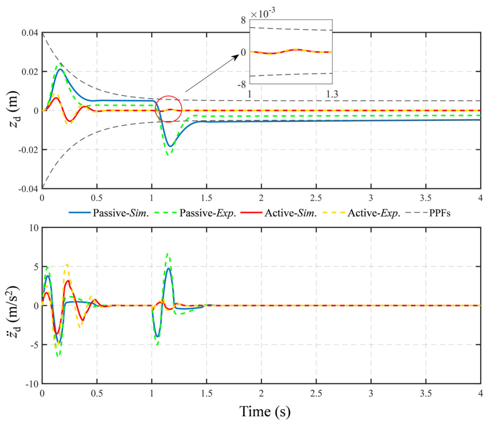
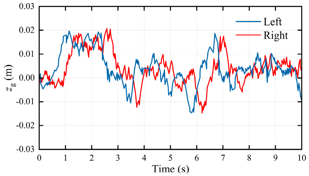
Scenario 2: As shown in
Figure 6, the random excitation is used as a broadband laboratory input to examine time-domain responses. It is not intended to reproduce a measured field operating condition.
The sinusoidal sweep and random input used in the experiments are laboratory excitations selected to cover the resonance range and broadband vertical disturbances relevant to seat-suspension evaluation. They are useful for comparing the passive and active configurations under repeatable conditions, but they do not reproduce measured field operating data from a specific target machine. Therefore, the present experiments provide laboratory-scale evidence for the feasibility of the proposed method. In future work, vertical acceleration data will be collected from representative field operations; the measured power spectral density, weighted RMS acceleration, and vibration dose value will then be compared with the laboratory inputs and replayed on the vibration platform before onboard validation.
Figure 7 compares the displacement and acceleration responses under the laboratory random excitation. Compared with the passive baseline, the active system reduces the dominant displacement and acceleration responses in both the simulation and experiment. However, the experimental active response still exhibits initial transient fluctuations and high-frequency components, which are likely related to actuation delay, static friction, sensor noise, and unmodeled mechanical dynamics. Therefore, the results indicate the feasibility of the proposed control strategy on the prototype test rig, rather than a complete validation under all field operating conditions.
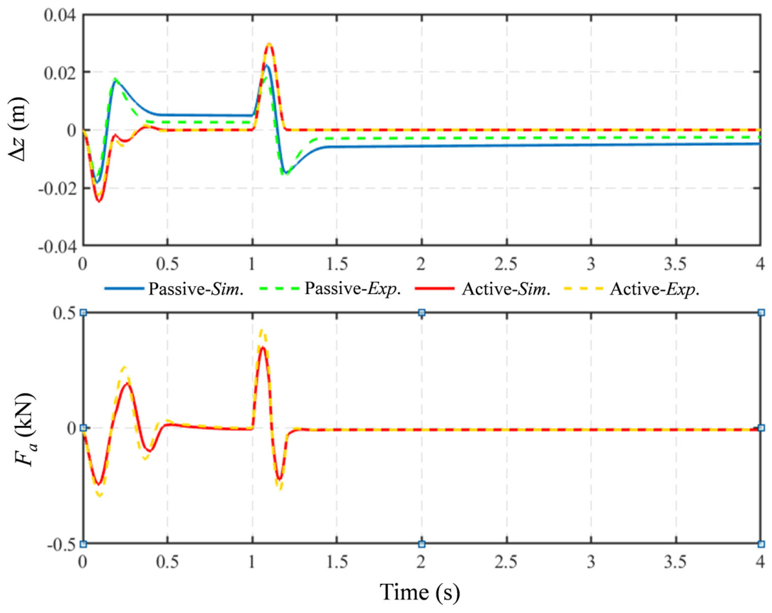
The upper panel of
Figure 8 shows the suspension deformation under random excitation. The active cases exhibit larger transient deformation than the passive cases, indicating that part of the available suspension stroke is used to reduce the acceleration response. Importantly, the deformation remains within the prescribed safety boundary in both the simulation and experiment. The difference between the simulated and experimental active responses also indicates the influence of physical nonlinearities, including spring nonlinearity, friction, and actuation delay.
The lower panel of
Figure 8 shows the active control force. The control force remains within the prescribed actuation limit and decreases as the system approaches steady state. Compared with the simulated response, the experimental force contains higher-frequency adjustments, which are likely caused by unmodeled friction, mechanical hysteresis, and sensor noise. These observations suggest that the proposed controller can balance ride-comfort improvement and actuation constraints on the prototype, but they also reveal the need for further validation under broader operating conditions.
Scenario 1 mainly evaluates steady-state acceleration transmissibility in the frequency domain, whereas Scenario 2 further examines random-excitation time-domain responses. Nevertheless, the present experiments do not include standardized shock pulses or measured field excitation from a target machine, which will be addressed in future work.
5. Conclusions
Motivated by vibration reduction for active seat-suspension systems, this paper proposes an acceleration-feedback adaptive weighted control strategy for a motor-driven laboratory prototype. The main findings and limitations are summarized as follows:
(1) By introducing an auxiliary virtual state variable, the proposed strategy provides a deformation-dependent weighting mechanism to coordinate ride comfort and suspension-stroke safety under the tested conditions; this problem-specific construction is the main methodological contribution of the work.
(2) Considering actuator delay and output saturation, an LMI-based controller is designed to guarantee asymptotic stability under the stated model assumptions. The nonlinear friction–damping behavior is represented through a bounded-disturbance treatment to support robust controller synthesis.
(3) Laboratory experiments show a 75–80% reduction in acceleration transmissibility in the 2.5–3 Hz band relative to the passive baseline. Under random excitation, the active system reduces the dominant displacement and acceleration responses while keeping the peak control force within approximately ±0.4 kN.
In summary, the proposed strategy demonstrates prototype-level feasibility in theoretical analysis, numerical simulation, and laboratory tests, but the current evidence does not yet constitute full field validation for a specific engineering application.
Future work will focus on closing the gap between laboratory prototype validation and engineering application. First, floor vertical acceleration will be measured under representative field operations of target construction machinery. Second, the measured profiles will be replayed on the vibration platform and compared with the present sinusoidal and random inputs using power spectral density, weighted RMS acceleration, and vibration dose value. Third, the model will be extended to include higher-order cabin dynamics, detailed human–seat coupling, explicitly modeled actuator nonlinearities, and a wider range of driver body masses before field implementation on a target machine. Although field validation remains necessary, the current study may provide a useful reference for future adaptive seat-control design in construction machinery (e.g., heavy-duty cranes) and other vehicle applications.