1. Introduction
Wind power is one of the most promising renewable energy sources, and it is expected to experience substantial growth. The wind industry must roughly triple its annual growth from 117 GW in 2023 to at least 320 GW by 2030 to meet the COP28 target and to ensure that global warming remains below 1.5 °C [
1]. New installations in 2023 increased to 117 GW for the total global capacity of wind energy, with China leading with a new record of 75 GW for new installations commissioned [
1]. Based on the WindEurope report, by the end of 2023, Europe installed 18.3 GW of new wind power capacity, a record amount, but this only accounts for half of the capacity planned to be built to meet the 2030 targets [
2]. Thus, the demand for wind energy capacity in the European Union is expected to increase significantly in the coming years, and new onshore and offshore wind power stations will be constructed. Wind power met 19% of the electricity demand in Europe in 2023. In Denmark, this percentage is 56%, which is the European country with the highest energy consumption covered by wind power, followed by Ireland with 37%, Germany with 31%, and the Netherlands with 27% in the year 2023 [
1]. Wind turbine installations are especially relevant in countries with cold weather conditions, like Norway, Germany, and Finland. Winters are the best season for wind energy due to generally higher wind speeds and increased air density with decreasing temperatures. However, ice formation is a significant problem [
3]. The roughness generated from ice accretion can significantly reduce the aerodynamics and, consequently, the power production of wind turbines [
4]. In Europe, 94% of wind farms have suffered different types of icing events, reducing power output losses to over 20% of the annual energy production [
5]. Three types of atmospheric icing are related to wind turbines, namely in-cloud, precipitation, and frost. Atmospheric icing affects wind farm operation by producing measurement errors, which results from icing affecting anemometers, wind vanes, or temperature sensors. Other issues that may occur include power losses by changing the shape and roughness of the blade airfoil, overproduction, mechanical and electrical failures, and safety hazards via ice shedding from the turbine blades, which can lead to personal injuries or structural and equipment damage [
6,
7].
Two different types of approaches can be distinguished to avoid this problem: active and passive methods. Nevertheless, only a few of these technologies are currently available on the market [
8]. Active methods include thermal and mechanical procedures that remove ice after it has formed, such as hot air flow [
9], hot water flow [
10], microwave heating [
11], and ultrasonic vibration [
12]. Active methods are usually very effective with fast response times but require high energy consumption and stopping operations, as well as interventions in the wind turbine’s structure [
13]. The most common passive methods are chemical methods, biochemical methods, and paint coatings that either reduce ice formation by preventing adherence to surfaces or shifting the freezing point of the surface. Passive coating strategies include superhydrophobic coatings [
14], slippery liquid-infused coatings, phase-changing materials [
15], or deicing fluids [
16]. Different types of surfaces inspired by lotus leaves have been developed to produce superhydrophobic surfaces and coatings by reducing the adhesion of water to the surface (anti-wetting behavior) through water contact angles larger than 150° and low sliding angles [
17]. Such superhydrophobic surfaces have been obtained by using low-surface-energy materials and by developing roughness on the micro- and nanoscales on the surface [
17,
18]. The air trapped within the micro-/nanotextured surface reduces the contact area with the droplet, which helps to delay droplet freezing and removes the droplets from the surface [
19]. Although the anti-icing performance of superhydrophobic materials has been widely recognized, the impact of high-speed, low-temperature, and subcooled microdroplets during wind turbine operation may still lead to direct pinning and freezing of water inside the superhydrophobic surface’s microstructure, resulting in limited anti-icing efficiency [
20,
21]. Liquid-infused surfaces (LISs) have been suggested to further improve the anti-icing performance of superhydrophobic surfaces by replacing the trapped air with a lubricant, which delays the ice formation process and reduces ice adhesion [
22].
Superhydrophobic and liquid-infused surface (LIS) technologies have been intensively investigated for passive anti-icing applications. Superhydrophobic surfaces reduce water residence time through high apparent contact angles and low droplet adhesion, whereas LIS coatings provide a lubricating interface that promotes droplet mobility and low ice adhesion [
20,
21,
22,
23]. However, the performance of superhydrophobic surfaces can deteriorate under realistic icing conditions when supercooled droplets penetrate the surface microstructure and freeze, thereby reducing the anti-icing effectiveness [
20,
21,
24]. LIS coatings can overcome several of these limitations by replacing the trapped air layer with a lubricant, resulting in lower contact-angle hysteresis and enhanced droplet mobility [
22,
23]. The implementation of passive anti-icing coatings on large engineering structures such as wind turbine blades remains a challenge. Besides achieving low ice adhesion, the coatings must exhibit sufficient attachment to the blade substrate and maintain surface functionality after installation and during operation. Therefore, LIS coating solutions that combine applicability with suitable coating architectures for effective accommodation of the lubricant and strong attachment to the substrate are of particular interest for wind energy applications [
25].
A variety of different chemical techniques have been described to prepare superhydrophobic surfaces, including chemical vapor deposition, solution immersion methods, electrochemical techniques, hydrothermal methods, and sol–gel processes. For further details, the reader is referred here to recent reviews [
26]. An interesting process to prepare LIS coatings is based on electrospinning highly porous nanofiber layers that have been proposed to achieve antimicrobial [
27,
28,
29], anti-corrosion [
30], and anti-icing properties [
31,
32,
33,
34]. In this process, the lubricant is applied into the pores of the nanofiber layers in a second separate step, most commonly by infiltration of the liquid lubricant. For example, the polymer poly(vinylidene fluoride-co-hexafluoropropylene), PVDF-HFP, has been used to prepare a nanofiber layer through electrospinning [
35]. In the second step, modifications have been applied to obtain improved anti-wetting properties via a subsequent addition of lubricants [
28,
36] or, alternatively, via vapor deposition techniques, which involves the addition of nanoparticles or silanization components [
37,
38].
In this study, we present a novel fabrication approach for a bi-layer liquid-infused surface (BLIS) coating for anti-icing applications on wind turbine blade surfaces. Liquid-infused surfaces have demonstrated promising anti-icing performance but practical implementation on wind turbine blades requires coating architectures that can be well attached to the substrate while maintaining the beneficial wetting and icephobic characteristics of lubricant-infused systems. To address this challenge, the BLIS coating developed in this study combines a PECA-based adhesive nanofiber layer with a porous PVDF-HFP nanofiber reservoir layer for lubricant retention. The coating is fabricated through a unique combination of electrospinning, electrospraying, and thermal curing, enabling the preparation of a liquid-infused anti-icing coating that can be thermally bonded to authentic wind turbine blade substrates. The anti-icing performance of the resulting coating is evaluated through wettability, droplet sliding, and ice adhesion measurements on wind turbine blade segments.
2. Materials and Methods
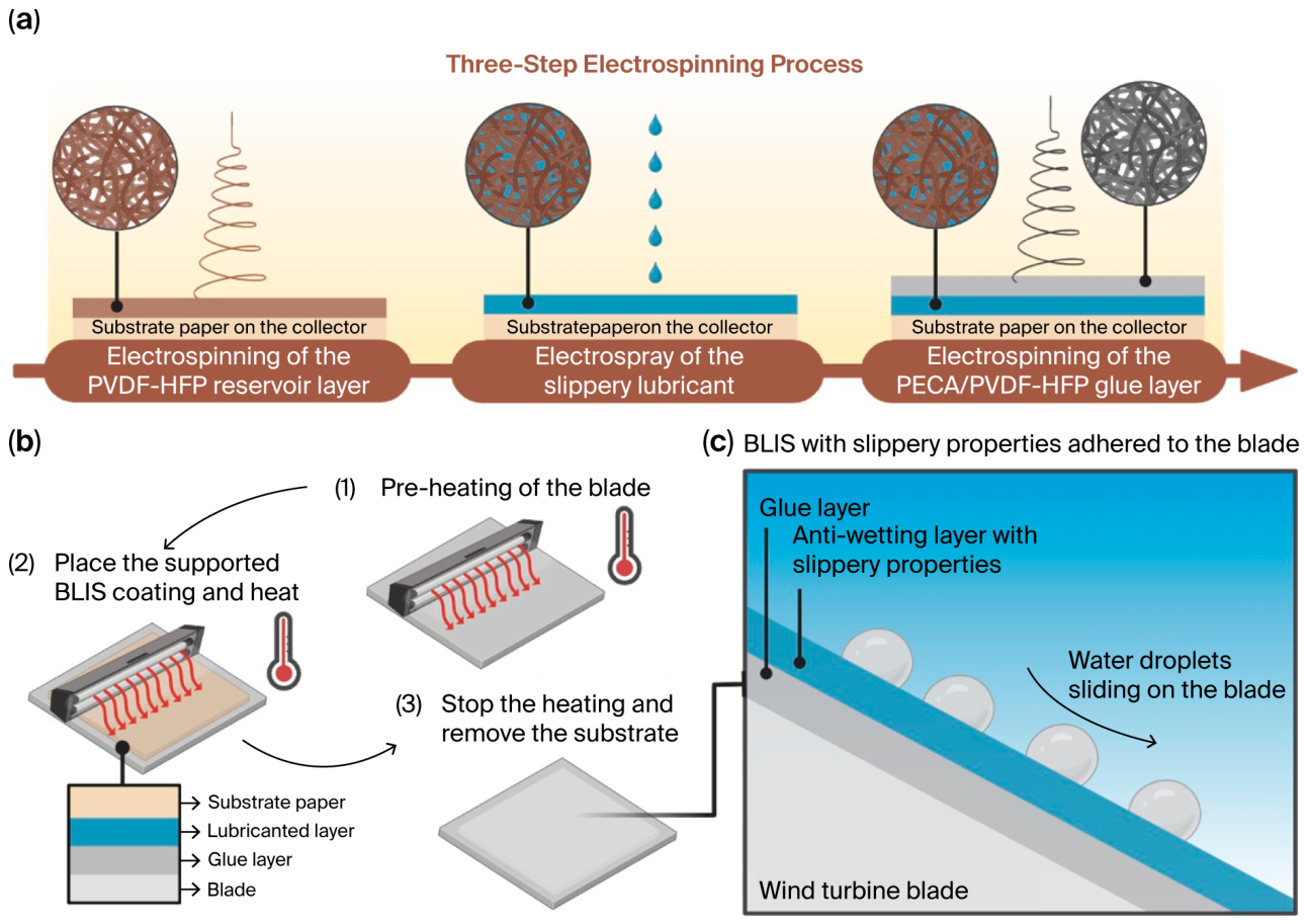
A schematic of the fabrication steps of the BLIS coating on the wind turbine blades is visualized in
Figure 1 and is based on the following steps: (a) a three-step electrospinning and electrospraying process to prepare the bi-layer nanofiber structure on a support paper and (b) transferring the bi-layer nanofiber structure to a blade and subsequent heating to attach it as a bi-layer LIS coating.
The top surface nanofiber layer of the BLIS system was prepared from a PECA-PVDF-HFP polymer blend and acted as reservoir layer for a lubricant (Krytox) to achieve slippery properties. The second PECA nanofiber layer was a glue layer to attach the top layer to the wind turbine blade surface by heat treatment and was prepared by electrospinning a polymer solution of ECA, a superglue component. Further details on the polymers, the electrospinning process of the layers and electrospraying the lubricant are described further below in this section.
2.1. Materials
Permabond 105 superglue containing ethyl-2-cyanoacrylate, ECA, was purchased from Diatom A/S, Hillerød, Denmark. Dimethyl sulfoxide, DMSO (CAS: 67-68-5), and acetone (CAS: 67-64-1) were purchased from Merck and used without previous purification. Poly(vinylidene fluoride-co-hexafluoropropylene), PVDF-HFP, in powder form, was purchased under the trade name Solef from Syensqo, Brussels, Belgium. Perfluoropolyether lubricant Krytox™ GPL 105 (The Chemours Company FC, LLC, Wilmington, DE, USA) was purchased from Diatom A/S, Hillerød, Denmark. Authentic wind turbine blade segments were supplied by Linari Engineering, Pisa, Italy.
2.2. Preparation of Polymer Solutions for Electrospinning
PECA, PVDF-HFP, and PECA/PVDF-HFP nanofiber polymer solutions were prepared for electrospinning of nanofiber coatings on a support paper. The PECA polymer precursor required for electrospinning the first PECA nanofiber layer (gluing layer) was prepared by PECA zwitterionic polymerization, following a methodology previously reported [
39]. In this process, DMSO was added to an ECA monomer droplet by droplet until a 1:1 volumetric ratio of ECA:DMSO was achieved. Then, the mixture was stirred for 5 min, and a viscous PECA-DMSO gel formed. The progress of the polymerization product has been monitored by Fourier transform infrared–attenuated total reflectance (FTIR-ATR). The FTIR spectra are included in
Figure S1 of the
Supplementary Materials. The PECA solution was prepared by dissolving PECA-DMSO gel in acetone at a concentration of 7% volumetric ratio, named PECA-7. Preparing PECA nanofiber coatings and attaching them to the blade surfaces is described in patent WO2023170642-A1 from Linari. The PVDF-HFP solution was prepared by dissolving the polymer powder in a mixture of DMF and acetone with a ratio of 1:1 and a polymer concentration of 50 mg/mL solvent, named PVDF-50. Based on studies on the miscibility of PECA and PVDF polymers [
40], a mixture of PECA/PVDF-HFP in solution was prepared by dissolving the PVDF-HFP polymer powder in DMF in a concentration of 100 mg/mL solvent and adding PECA-7 solution in a volumetric ratio of 1:1, which corresponds to a 70 to 30 weight ratio between PVDF-HFP and PECA in the structure of the final fibers. This specific PECA/PVDF-HFP blend composition was selected based on previous studies demonstrating good miscibility between both polymers and based on promising results in preliminary electrospinning trials. The PECA component is required to provide adhesion during the subsequent thermal bonding step, whereas PVDF-HFP improves compatibility with the upper lubricant-containing reservoir layer and contributes to maintaining the fibrous structure during heat treatment. A weight ratio of approximately 30 wt.% PECA and 70 wt.% PVDF-HFP was found to provide stable electrospinning conditions, sufficient adhesion after thermal treatment, and good compatibility with the PVDF-HFP reservoir layer. Preliminary experiments using separate PECA and PVDF-HFP layers resulted in insufficient interfacial bonding and partial delamination of the bilayer structure.
2.3. Electrospinning the Nanofiber Layers
The polymer fibers were prepared by electrospinning using RT Advanced electrospinning equipment (Linari Engineering, Pisa, Italy). The electrospinner includes a vertical grounded collector and a syringe holder with a translating guide and a syringe pump. The syringe containing the polymer solution was attached to a needle. All spinning was conducted at 23 ± 5 °C and a relative humidity of less than 40%. Electrospinning the polymer solution to prepare PECA, PVDF-HFP, and PECA/PVDF-HFP fibers was carried out using an RT Advanced electrospinner from Linari Engineering, Pisa, Italy (shown in
Figure S2). Electrospinning parameters, including voltage, flow, and distance between the tip and the collector, were optimized for each solution and are included in
Table S1.
2.4. Preparation and Assembly of BLIS Nanofiber Architecture (BLIS Coating System)
PECA, PVDF-HFP, and PECA/PVDF-HFP nanofiber polymer solutions were each prepared for electrospinning the different nanofiber coatings on the support paper. The bi-layer liquid-infused surface, BLIS, was prepared by electrospinning a PVDF-HFP layer to create a surface coating with slippery properties for anti-icing applications and a PECA/PVDF layer to glue the coating to wind turbine blades firmly in a subsequent IR heating process step. Two electrospinning steps and one electrospraying step were performed to obtain the final BLIS coating, as illustrated in
Figure 1a. First, the reservoir layer of the lubricant was prepared by electrospinning the PVDF-50 solution. Secondly, the Krytox lubricant was electrosprayed without additional solvents. During the electrospraying process, no fibers were produced, but tiny droplets formed and detached from the needle and flew to the collector while impregnating the reservoir layer of the PVDF-HFP fibers.
Figure S3 includes photos illustrating the electrospraying process. Finally, the glue layer was electrospun on top of the PVDF-HFP layer, using the PECA/PVDF-HFP solution. Parameters for each electrospinning process were carefully optimized and are included in
Table S2. The preparation of a bi-layer structure, consisting of pure PECA fibers and a pure nanofiber PVDF reservoir layer, was also investigated. However, the two layers showed low compatibility, resulting in the two nanofiber layers separating at the interface.
2.5. Heat Treatment to Adhere Nanofiber Coatings to Blade Surfaces
A thermal treatment with a homemade infrared lamp developed by Linari Engineering was applied to adhere the nanocoating layers to actual wind turbine blade segments after transferring and pressing them to the blade surface with the support paper facing upwards. Pictures of the blades are shown in
Figure S4a. The heat treatment process is illustrated in
Figure 1b, and a schematic of the final structure with the sequence of nanofiber layers in the bi-layer LIS coating on the blade is shown in
Figure 1c. The more detailed heating procedure consisted of pre-heating the surface of the blade, placing the coating on the blade and performing a final heating treatment of the nanofiber layers with the infrared lamp. The nanofiber coatings were heat-treated using the infrared (IR) lamp positioned at a distance of 5 cm from the substrate surface. The substrate surface temperature was monitored with an infrared thermometer and maintained at the desired temperatures of 160, 180, or 200 °C within a tolerance of ±5 °C for 2 min.
In the last step, the paper substrate was removed from the BLIS coating. The temperatures selected for the infrared heat treatment were guided by the thermal properties of the coating components and by preliminary adhesion experiments. PECA exhibits thermal softening and the onset of thermal degradation at approximately 165 °C, as confirmed by the TGA results presented later in this work, whereas PVDF-HFP remains thermally stable up to temperatures above 300 °C. Therefore, temperatures of 160 °C, 180 °C, and 200 °C were selected to investigate the effect of increasing PECA softening and bonding to the blade substrate while maintaining the structural integrity of the PVDF-HFP reservoir layer. A short treatment time of 2 min was chosen to provide sufficient thermal activation of the PECA component while minimizing thermal degradation of the polymer network, the lubricant and the surface of the blade.
2.6. Characterizing Polymer Solutions and Coatings
A Phenom Pro Desktop SEM from Thermo Fisher Scientific (Eindhoven, The Netherlands) was used to perform the morphological characterization of the nanofiber structures and coating samples. The samples were coated with a layer of gold–palladium alloy before imaging using a sputter coater (Polaron SC7695, Polaron Equipment Ltd., Watford, UK).
The thermal treatment used to adhere the coating to the blade was optimized by analyzing the thermal stability of the polymer fibers and analyzing the attachment to the blade by scratching. Thermogravimetric analysis was performed using an STA 449 F3 Jupiter thermal analyzer (NETZSCH GmbH, Selb, Germany) using a 5 °C·min−1 ramp and air atmosphere to investigate the thermal stability of the polymer fibers and a 1 °C·min−1 ramp and air atmosphere for the liquid lubricants.
Fourier transform infrared–attenuated total reflectance (FTIR-ATR) spectra were recorded using an FTIR spectrometer, Spectrum ONE, Perkin Elmer Inc., Waltham, MA, USA) operating between 4000 and 400 cm−1 with 4 scans and a 4 cm−1 resolution to observe chemical changes in the polymer structure of the nanofibers during the heat treatment process. Profilometry measurements were performed to obtain the topography parameters of the polymer fibers using a Cyberscan Vantage Profilometer (Cyber Technologies, Eching, Germany).
After the coating was adhered on a piece of a wind turbine blade, the wettability was evaluated by measuring the water contact angle, the slippery properties were measured at a low temperature, and the ice adhesion strength was evaluated using a home-built ice adhesion test apparatus. A Kruss Drop Shape Analyzer DSA 25 (Krüss Scientific, Hamburg, Germany) was used for the wettability studies on the nanofiber coatings, measuring static liquid contact angles and quantifying the hydrophobicity. The volume used for the droplets was 8 μL.
Sliding measurements were performed using 20 μL water droplets and a digital protractor (Proster, China) at different temperatures. A climate chamber provided by UltraCella with an EVD module for remote monitoring was used to recreate low-temperature conditions to measure sliding velocity properties at low temperatures. The droplet volume used for sliding velocity measurements was 30 μL, two tilt angles were tested, 45° and 60°, and two temperatures, 0 and 5 °C, were evaluated. The displacement of a water droplet over a defined period of time was measured and the sliding velocity was calculated from the travelled distance divided by the elapsed time. After the sliding experiment, another test was performed at sub-zero temperatures. A blade segment coated with the BLIS was sprayed with water and placed horizontally. Then, the climate chamber was cooled down to −10 °C. The water took around 15 min to completely freeze on the blade segment. A home-built shear adhesion apparatus was used to measure the ice adhesion strength of the samples, utilizing a pneumatic piston (MQQTB16-50D, SMC Corp., Tokyo, Japan) with a load cell (8413-5050, 50N, Blichfeld Power & Measurements A/S, Farum, Denmark) attached to a plastic pushing rod. Ice/coating samples were prepared by filling Teflon cuvettes with 0.8 mL of pure water and freezing them at −15 °C for 1 h. Before measurement, the temperature was set, and the samples were allowed to equilibrate for an additional hour. An insulated stainless-steel chamber with square indents (20 mm × 20 mm × 0.5 mm) held the coatings, which were secured to the stage and temperature controlled by a recirculating chiller with flowing cooled fluid through a connected baseplate. The apparatus pushed the ice-filled Teflon cuvettes that were on top of the sample surfaces. The apparatus is illustrated in
Figure S5. The pushing force was controlled using a pressure regulator (ARX20-F01, SMC Corp.) set to 3.0 bar with an adjustable flow restriction valve (AS1002F, SMC Corp.) set to 10 mL min
−1. To perform the experiment, the wind turbine blade segments were cut and polished to obtain 20 mm × 20 mm × 0.5 mm squares and coated with the corresponding tested coatings. Four replicates of each sample were tested.
3. Results
The properties of BLIS coatings developed in this study strongly depend on the fabrication conditions during electrospinning, electrospraying, and the subsequent heat treatment procedure to attach the layers with the superglue component (PECA) to the wind turbine blades. In this section, the thermal stability, microstructure, and surface properties of the nanofiber layers in the BLIS coating are analyzed as a function of the curing temperature in the heat treatment process.
3.1. Microstructure of Nanofiber Layers in BLIS Coating After Electrospinning
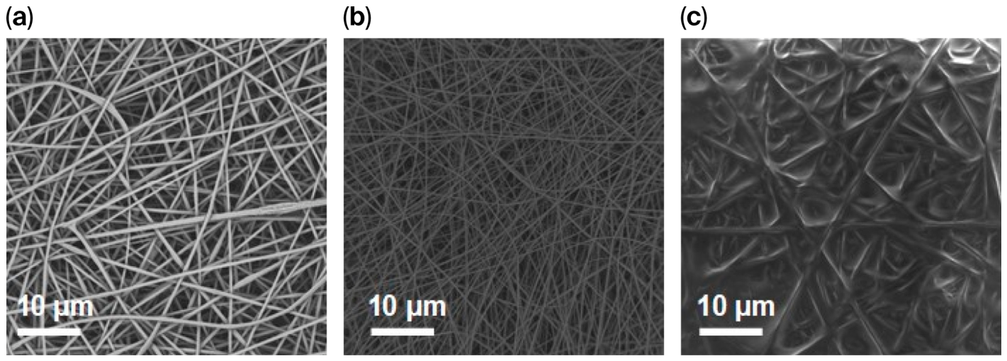
Figure 2 shows SEM pictures of the surface microstructure of the single nanofiber layers of the BLIS coating after electrospinning on the support paper.
Figure 2a illustrates the PECA/PVDF-HFP glue layer nanofiber structure before the heat treatment step with fiber diameters in the range of 200 nm and 350 nm.
Figure 2b shows the PVDF-HFP reservoir layer nanofiber structure with fiber diameters between 150 nm and 250 nm after electrospinning and before lubricant impregnation and heat treatment.
Figure 2c reveals that nanofibers of the same PVDF-HFP layer have been swollen with significantly larger diameters of 300 to 500 nm after lubricant addition. The ability of the fibers to swell indicates good compatibility between the lubricant and the fibers, which means the polymer nanofiber can retain and contain the lubricant, which is one of the main requirements of liquid-infused surfaces and is often a concern if not achieved.
3.2. Thermal Stability and Microstructural Development of BLIS Nanofiber Layers During Heat Treatment
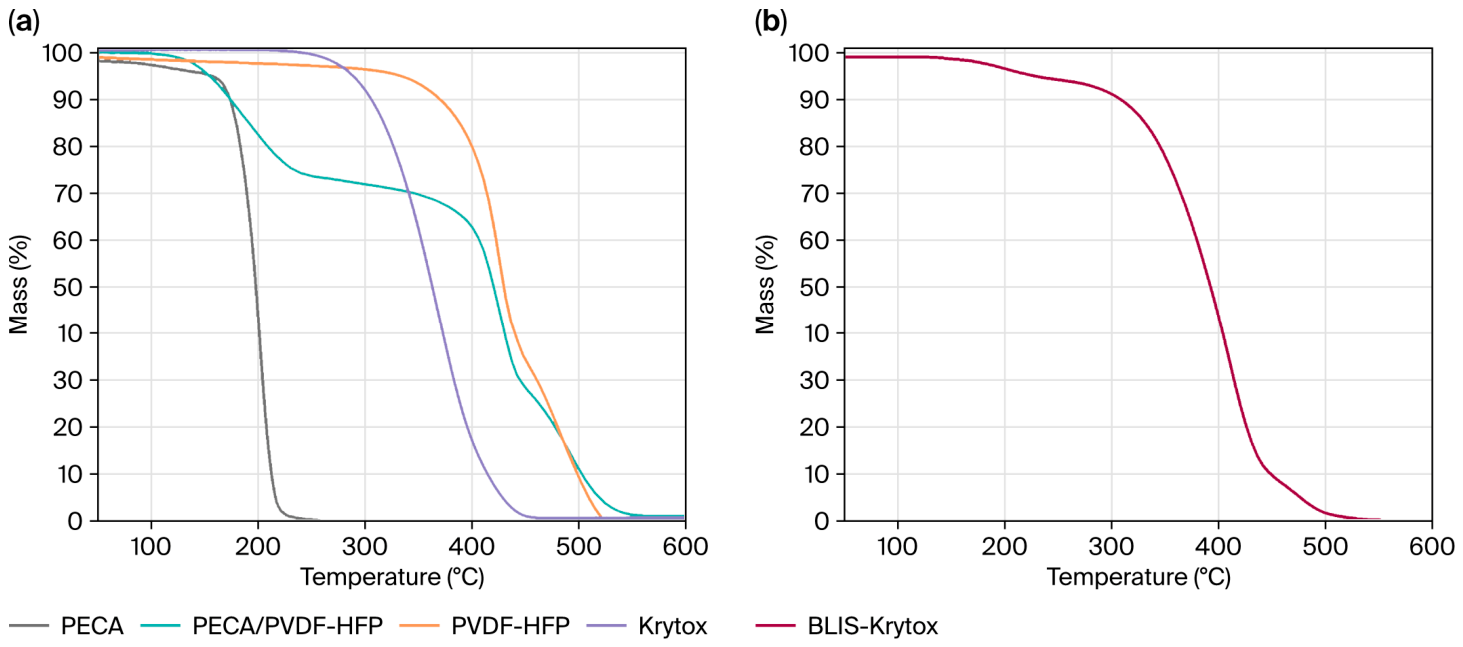
To optimize the heat treatment procedure for curing and to apply the nanofiber layers in a BLIS coating, the combination of the first nanofiber glue layer of the PECA/PVDF-HFP nanofiber and the second PECA/PVDF-HFP top layer has been investigated. For this purpose, the thermal stability of the BLIS coating components, including the polymers and the different nanofiber layers were analyzed by thermogravimetric analysis (TGA). In
Figure 3a, the degradation curves of all the polymer components in the nanofibers of PECA, PECA/PVDF-HFP, PVDF, and the additional Krytox lubricant are plotted. The pyrolysis of the PECA polymer shows thermal degradation in one step, starting at 165 °C. The PVDF-HFP nanofiber polymer shows degradation in two steps, beginning at 350 °C and 400 °C according to the literature [
40]. The TGA curve corresponding to PECA/PVDF-HFP fiber degradation (green curve) is in accordance with the theoretically calculated composition and reveals that the first mass loss below 250 °C of 28% corresponds to the PECA polymer and the second and third mass losses of 72% below about 420 °C and 470 °C correlate to the PVDF-HFP layer degradation. Previous studies reported that a heat treatment temperature close to these degradation temperatures will destroy the PECA fiber if the fibers are glued to a substrate [
39]. The TGA results show that the PVDF-HFP surface layer is thermally stable up to 350 °C, and it is thus expected to not be affected by the thermal treatment procedure, which is required for attachment close to the PECA degradation temperature of 165 °C. The Krytox lubricant pyrolysis curve shows a maximum degradation temperature of 360 °C, far above the heat treatment window of PECA. The entire BLIS coating system, including the Krytox lubricant, was also analyzed by thermal analysis, which provides information about the degradation of the entire coating during heat treatment (
Figure 3b). The TGA results indicate that up to 250 °C, only 5% of the coating mass is lost due to PECA degradation. Between 250 °C and 550 °C, a larger weight loss (corresponding to the remaining 95% of weight) was observed, which corresponds to removal of the PVDF-HFP and Krytox lubricant.
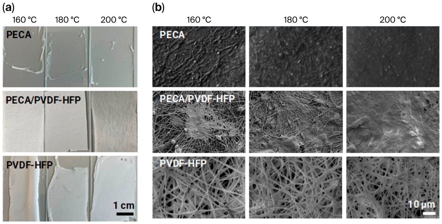
Based on the above thermal stability test results by TGA, three temperatures, 160 °C, 180 °C, and 200 °C, all below PECA’s degradation temperature, were chosen to test the adhesion of the coating to pieces of wind turbine blades. The heat treatment test to evaluate the attachment to a surface was first performed using glass substrates before the final coating application on wind turbine blade pieces was investigated. The fiber microstructures were visualized by SEM, and adhesion to the blade segment was qualitatively evaluated from photos after heat treatment for 2 min at different temperatures (
Figure 4a) and by trying to scratch the substrate using tweezers or removing the coating by attachment and subsequent removal of sticky tape (sticky tape test).
Figure 4a shows the macroscopic appearance of PECA, PECA/PVDF-HFP, and PVDF-HFP nanofibers on the glass substrates after heat treatment with an IR lamp from the surface at temperatures of 160 °C, 180 °C, and 200 °C for 2 min. The pictures reveal that adherence to the glass substrate improves with increasing temperature from 160 °C to 200 °C, which is expected due to increased melting and curing of the PECA polymer acting as glue. Good adherence of the nanofiber layer to the glass substrate has been observed if the coating does not delaminate visually and becomes transparent in color, which is due to melting and removal of pores in the nanofiber layers (
Figure 4a, the PECA coatings in the top row of pictures). In contrast, delamination and the white color of the nanofiber coating indicates insufficient adherence of the PVDF-HFP layers to the glass substrate (
Figure 4a, the PVDF-HFP coatings in the bottom row).
The SEM surface images of the PECA nanofiber microstructure (
Figure 4b) show that the distinct nanofiber structure gradually disappears with increasing temperature and transforms into a less rough surface. This is also confirmed by roughness measurements (see plots in
Figure 5 further below and subsequent discussion). It is expected that the selected short 2 min temperature treatment time only results in a change in the microstructure but does not lead to PECA coating decomposition. The PVDF-HFP nanofibers (
Figure 4b, bottom row) retain their structure even at a temperature of 200 °C but show some swelling and flattening. The nanofiber blend coating of PECA/PVDF-HFP showed an intermediate behavior with better adherence of a larger fraction of the nanofiber coating to the glass substrate with increasing temperature but melting and loss of the fiber structure.
In summary, the SEM observations reveal a clear process–structure relationship during the thermal treatment of the nanofiber layers. Increasing the heat-treatment temperature promotes partial melting and coalescence of the PECA-containing fibers, resulting in a progressive reduction in porosity and surface roughness. This structural evolution is beneficial for adhesion because the softened PECA polymer can flow and establish improved interfacial contact with the substrate, thereby enhancing the bonding strength of the coating. In contrast, the PVDF-HFP fibers largely retain their fibrous morphology at the investigated temperatures owing to their significantly higher thermal stability. Consequently, the bilayer architecture combines two distinct functions: the PECA-containing layer acts as a thermally activated adhesive layer, whereas the PVDF-HFP layer preserves the porous nanofiber structure required for lubricant retention and anti-wetting performance. The observed microstructural changes therefore provide the basis for the subsequent evolution of wettability and anti-icing properties discussed in
Section 3.3 and
Section 3.4.
3.3. Wettability of Nanofiber Layers and BLIS Coating as Function of Heat Treatment Temperature
Based on the heat treatment tests, the BLIS coating was assembled by a layer-by-layer application of a first polymer nanofiber of the PECA/PVDF-HFP polymer blend (glue layer) and a top layer of PVDF-HFP (reservoir layer for lubricant) and heat treatment at 200 °C, which resulted in good adherence to the blade substrate. While the first PECA/PVDF-HFP fiber layer on the blade substrate showed good adherence to the substrate due to melting, the microstructure of the top PVDF-HFP was not affected by the heating temperature of 200 °C and could be used as a reservoir layer for the lubricant.
For the application as an anti-icing coating, the wettability of the BLIS coating structure is important and is closely related to the chemical nature, microstructure, and resulting surface roughness of the polymer [
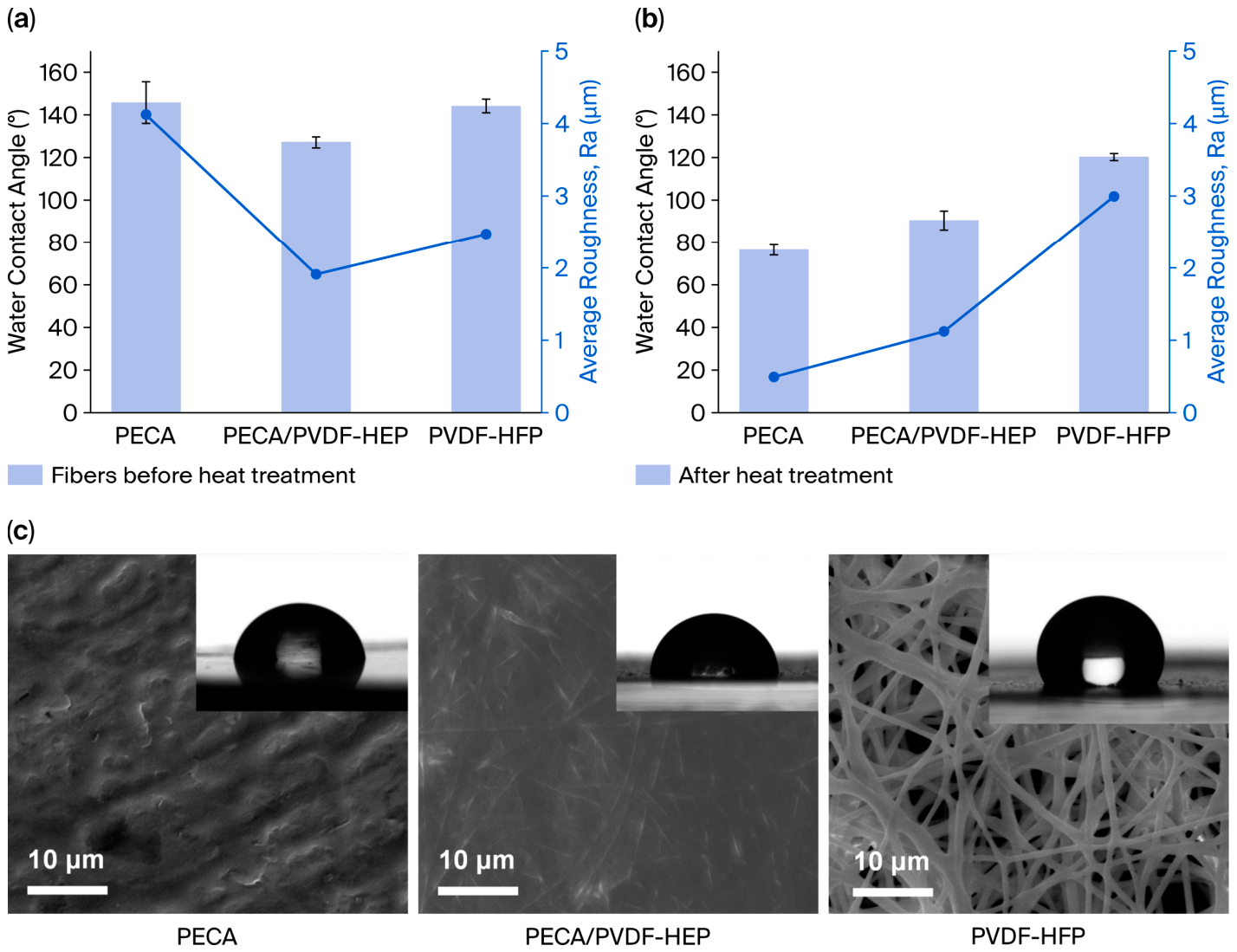
23]. The water contact angle measurements and roughness of the PECA, PECA/PVDF-HFP, and PVDF-HFP nanofiber coatings before and after the heat treatment are plotted in
Figure 5a and
5b, respectively. Water droplet formation on the coating surfaces (for contact angle measurements) is visualized for the different nanofiber coatings after heat treatment at 200 °C and without lubricant addition in
Figure 5c.
The water contact angle of all as-spun fibers exceeded 120°, correlating with the roughness Ra of the coating (see
Figure 5a). The water contact angle and the roughness Ra of the as-spun PECA nanofibers is 142° and over 4 µm, which can be associated with the smaller size of the PECA nanofibers, corresponding to a higher rugosity (see SEM pictures in
Figure 2 for reference). The results further demonstrate the strong correlation between surface morphology and wettability. Heat treatment reduces the roughness of the PECA-containing coatings due to fiber melting and consolidation, which decreases the contribution of surface texturing to hydrophobic behavior. Consequently, the contact angle decreases despite the unchanged chemical composition of the polymer. In contrast, PVDF-HFP retains a larger fraction of fibrous morphology and roughness after thermal treatment, thereby preserving higher contact angles. These observations indicate that both the chemical composition and the retention of the nanofiber microstructure are essential for maintaining the anti-wetting properties of the coating.
The chemical nature of the surface (hydrophobic PVDF vs. less hydrophobic PECA) seems not to affect the surface wettability of the nanofibers before heat treatment. However, after heat treatment of the nanofiber layers (
Figure 5b), both the water contact angle and the mean roughness (Ra) increase with increasing PVDF-HFP content in the coating, following the order PECA < PECA/PVDF-HFP < PVDF-HFP. This behavior is attributed to the greater retention of the nanofibrous morphology with increasing PVDF-HFP content, resulting in higher surface roughness and enhanced hydrophobicity. For comparison, the roughness properties of the different nanofiber layers treated at 160 °C and 180 °C were also analyzed, and the results are included in
Table S3 of the
Supplementary Materials. These results are in line with the tendency shown in
Figure 5.
Table S3 also includes R
q, R
t, R
sk, and R
ku parameters for all studied samples.
Figure 5c shows SEM micrographs of the surface morphology for all three different coatings of PECA, PECA/PVDF-HFP, and PVDF-HFP after heat treatment together with the water contact angle, further visualizing the difference in roughness and microstructure of these coatings. In conclusion, in the double-layer system (
Figure 5b, in the middle) the first PECA/PVDF-HFP layer achieves good adhesion to the blade substrate and also ensures good compatibility with the top PVDF-HFP layer. However, the water contact angle is below 100°, which does not ensure sufficiently high de-wetting. In contrast, the single PVDF-HFP coating system (
Figure 5c, on the right) is stable throughout the heat treatment, ensures adhesion, and can maintain a sufficiently high wetting angle of about 120° after attachment to the blade, with good compatibility with the lubricant.
The wetting angles of the full PECA/PVDF-HFP layer with lubricant (BLIS coating) before heat treatment (as electrospun) and after attachment to a blade at 200 °C, are 120° and 112°, respectively (results are shown in
Figure S6 in the
Supplementary Materials), and are comparable to the wetting angle of the single PVDF-HFP surface layer reported in
Figure 5b.
Figure S6 in the
Supplementary Materials reveals that ice formed and covering the surface of a wind turbine blade at −10 °C after a spray test is less strongly attached to the wind turbine surface coated with the nanofiber BLIS coating compared to the uncoated blade surface. This shows that the hydrophobic BLIS coating is a good anti-wetting surface even though the contact angle is lower than in some superhydrophobic surfaces, such as surfaces with the lotus effect that can reach higher contact angles of 150° or more.
3.4. Water Droplet Sliding and Ice Adhesion Tests with Nanofiber BLIS Coatings
The sliding and anti-icing properties of the full BLIS coating were evaluated and compared with the properties of the single nanofiber coatings.
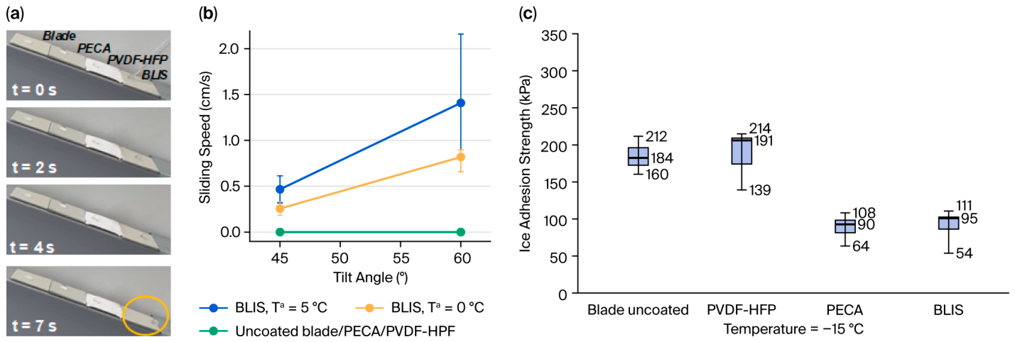
Figure 6a shows photos of the sliding speed experiments with water droplets on the surfaces of a blade piece after different sliding times of 0, 2, 4, and 7 s at a tilting angle of 45° (photos from top to bottom) and at room temperature. The four different segments on the wind turbine blade surface from the left top to right bottom (each covered by a water droplet) resemble an area of an uncoated blade, an area coated with a PECA nanofiber layer, an area with a PECA/PVDF-HFP nanofiber bi-layer (contains no lubricant), and an area with the full BLIS coating (PECA/PVDF-HFP layer with lubricant).
The area of the blade with the BLIS coating (area in right part of each photo for 0, 2, 4, and 7 s reveals that the water droplet only slides on the blade segment coated with BLIS, leaving the blade clean and dry, as marked on the photo with a yellow circle. More sliding speed measurements have been conducted for the BLIS coating at three different tilt angles of 0° (no sliding), 45°, and 60° and at two more temperatures of 0 and 5 °C. The results of these measurements are summarized in the plot in
Figure 6b. For comparison, the results for the uncoated blade are added for a temperature of 25 °C.
The main conclusion that can be obtained from the experiment is that the full BLIS coating maintains slippery properties at low temperatures, while the water droplets get stuck on the uncoated blade with the PECA and BLIS coating without lubricant, even at high tilt angles.
Figure 6c includes results of the measurement of shear adhesion strengths of pure ice cylinders frozen on pieces of the coated wind turbine blade. Examples of raw data in terms of graphs show the applied shear force as a function of time (
Figure S6).
These results indicate that the BLIS coating decreases the shear adhesion strength by 50% compared to the uncoated wind turbine blade, (i.e., from 184 kPa to 95 kPa). The improved anti-icing performance can be directly related to the hierarchical structure of the BLIS coating. The thermally bonded PECA layer ensures stable attachment of the coating to the blade substrate, while the porous PVDF-HFP layer serves as a reservoir for the lubricant. The lubricant-infused surface reduces contact line pinning and promotes droplet mobility, resulting in reduced residence times of water on the surface and a lower probability of ice formation. Furthermore, the liquid interface between the ice and the coating decreases mechanical interlocking, which contributes to the observed reduction in ice adhesion strength. The results therefore demonstrate a direct connection between the fabrication process, the resulting bilayer microstructure, and the macroscopic anti-icing performance.
The reservoir layer, which is the PVDF-HFP layer, has similar shear adhesion strengths than the blade, with an average of 191 kPa. The PECA coating was also analyzed, as previously reported, as an anti-wetting material, also showing low ice adhesion strength similar to the BLIS coating. However, considering the combination of unique properties, including low wettability, high droplet sliding velocity, and low ice adhesion strength, the BLIS coating is still the best option for anti-icing coatings on wind turbine blades.
4. Discussion
In this study, a transparent bi-layer liquid-infused surface (BLIS) coating was developed using electrospinning and thermal curing to combine a PECA-based adhesive layer with a lubricant-infused PVDF-HFP nanofiber layer on wind turbine blade substrates. The coating performance is governed by the complementary functions of the individual layers and their response to the thermal curing process. Thermal analysis demonstrated that PECA undergoes softening within the curing temperature window, whereas PVDF-HFP remains thermally stable up to significantly higher temperatures. Consequently, heat treatment activates the adhesive function of PECA and promotes bonding to the blade substrate, while preserving the porous PVDF-HFP nanofiber structure required for lubricant retention. This interpretation is consistent with the improved adhesion and transparency observed after curing and the retention of the PVDF-HFP nanofiber morphology. An important feature of the BLIS architecture is the PECA/PVDF-HFP blend layer, which acts as an interfacial transition layer between the blade substrate and the PVDF-HFP reservoir layer. During fabrication, bilayers consisting of pure PECA and pure PVDF-HFP exhibited poor compatibility and interfacial separation, whereas incorporation of PVDF-HFP into the adhesive layer enabled stable multilayer assembly. Furthermore, the swelling of PVDF-HFP nanofibers after lubricant infiltration demonstrates a strong affinity between the fluorinated polymer network and the Krytox lubricant, which is a key requirement for lubricant-infused surfaces [
23].
The reduction in ice adhesion for the BLIS coating can be attributed to the presence of a lubricant-rich, mechanically mobile interface between the ice and the coating. In contrast to dry textured coatings, where water can penetrate the surface structure and freeze into the roughness, the lubricant-infused PVDF-HFP nanofiber network reduces direct ice-solid contact and limits mechanical interlocking between ice and the underlying polymer structure. The lubricant layer can therefore act as a weak shear plane during ice adhesion testing. This interpretation is supported by the comparison between the uncoated blade, the dry PVDF-HFP reservoir layer, and the full BLIS coating. The dry PVDF-HFP layer showed an ice adhesion strength similar to the uncoated blade, whereas lubricant infusion reduced the ice adhesion strength from 184 kPa for the uncoated blade to 95 kPa for the BLIS coating. This demonstrates that the reduced ice adhesion is not caused by the fluorinated polymer layer alone, but by the combination of the porous PVDF-HFP reservoir and the retained lubricant.
Compared with previously reported liquid-infused anti-icing surfaces [
29,
30,
31,
33], the present BLIS coating follows the same general icephobic principle of replacing a rigid solid/ice interface with a lubricant-mediated interface. However, the present architecture additionally addresses an important practical requirement for wind turbine applications which is attachment to an authentic blade substrate. The PECA/PVDF-HFP transition layer provides adhesion to the blade during thermal curing while maintaining compatibility with the PVDF-HFP lubricant reservoir layer. Therefore, the main advantage of the BLIS coating is the combination of reduced ice adhesion, low-temperature droplet mobility, transparency, and blade-compatible attachment. Because ice adhesion values are strongly affected by test geometry, temperature, ice formation protocol, and substrate type, direct numerical comparison with literature values should be interpreted with caution. The internal comparison with the uncoated blade and the dry PVDF-HFP layer is therefore particularly important for demonstrating the functional benefit of the lubricant-infused bilayer design.
From an application perspective, transferring the BLIS concept from laboratory-scale samples to full-scale wind turbine blades presents several technical challenges. Although electrospinning is a scalable manufacturing technology capable of producing uniform nanofiber coatings over large areas, the application and curing of such coatings on large, curved, and geometrically complex blade surfaces remain to be demonstrated under industrial conditions. Future developments will require scalable coating and attachment processes compatible with blade manufacturing, installation, and maintenance operations. Key considerations include coating uniformity, application efficiency, processing time, and overall cost. Ongoing pilot-scale activities, including wind tunnel testing and field validation, are evaluating the performance and practical implementation of electrospun anti-icing coatings on wind turbine blades, providing important insights into process scalability and techno-economic feasibility.
While the present results demonstrate the feasibility of the BLIS coating concept, long-term durability remains a critical requirement for practical deployment. The current study focuses on coating fabrication, adhesion, wettability, droplet mobility, and ice adhesion reduction, whereas environmental aging and operational durability were beyond the scope of this work. Future work should therefore evaluate BLIS coatings under conditions representative of wind turbine operation, including accelerated UV aging, temperature and freeze–thaw cycling, rain and particle erosion, mechanical abrasion, and prolonged moisture exposure. Long-term lubricant retention within the porous PVDF-HFP nanofiber structure should also be investigated, as lubricant depletion is a known limitation of liquid-infused surfaces and may affect the durability of the anti-icing performance. Such studies are essential for assessing the operational lifetime and practical applicability of BLIS coatings in large-scale wind energy systems.




 ,
,