Article

Influence of Slot Angle and Hole Spacing on Directional Crack Propagation in Sandstone with V-Shaped Slotted Blastholes

1
School of Civil and Hydraulic Engineering, Chongqing University of Science and Technology, Chongqing 401331, China
2
Key Laboratory for Highway Bridge and Tunnel of Shanxi Province, Chang’an University, Middle-Section of Nan’er Huan Road, Xi’an 710064, China
3
School of Civil Engineering, Chongqing Jiaotong University, Chongqing 400074, China
4
T.Y. Lin International Engineering Consulting (China) Co., Ltd., Chongqing 401121, China
*
Authors to whom correspondence should be addressed.
Appl. Sci. 2026, 16(12), 6112; https://doi.org/10.3390/app16126112
Submission received: 21 May 2026 / Revised: 9 June 2026 / Accepted: 12 June 2026 / Published: 17 June 2026

Abstract

To improve the directional propagation of blasting-induced cracks in sandstone and reduce over-excavation, under-excavation, and surrounding-rock damage caused by conventional circular blastholes, circular and V-shaped slotted blasthole models were established in LS-DYNA. The ALE fluid–solid coupling algorithm was adopted to investigate the effects of slot angle on the effective stress field, crack propagation pattern, and crack control index. The stress field theory at the tip of the V-shaped slot was further used to explain the directional cracking mechanism. On this basis, a two-hole V-slotted blasting model is established to analyze the influence of hole spacing on crack penetration. The results show that the V-shaped slot can form an obvious stress concentration at the tip, which changes the crack from approximately isotropic extension to directional extension along the direction of the slots. Under the present two-dimensional homogeneous sandstone model with simultaneous initiation, the 60° slot angle corresponds to the highest peak effective stress and crack control index. For the synchronized two-hole model, when the hole spacing is 70–90 cm, namely the ratio of hole spacing to blasthole diameter is approximately 14–18, the inter-hole crack penetration effect is better, and the proportion of effective cracks along the slot direction is about 80%. These results provide baseline numerical references for sandstone-controlled blasting parameter design under the modeling conditions of this study.

1. Introduction

Blasting technology is commonly used in tunneling, mining, and underground space engineering, and rock fragmentation methods; their rock-breaking efficiency and contour control effect directly affect the quality of construction, safety, and economy. In the traditional circular hole blasting process, the explosive stress waves and explosive gases usually act on the rock body around the hole wall in a nearly uniform manner; the energy release is weak in direction, which can easily lead to over-excavation, under-excavation, excessive damage with associated blasting vibrations and other post-work problems [1,2,3,4]. In order to realize the directional release of blasting energy and the controllable expansion of cracks, the directional fracture control blasting technology has gradually received attention. Among them, V-shaped slotted blastholes are made by prefabricating slots in the hole wall or rock body, so that the tip of the slots generates a localized stress concentration, which guides crack initiation and expansion in a predetermined direction [5,6]. Compared with conventional circular holes, V-shaped slotted blastholes have a greater potential for application in terms of improving crack guidance, reducing damage in non-target directions, and improving the molding quality of excavation contours.
In recent years, scholars have carried out a large number of studies on the mechanism of slotting hole blasting, crack extension, and optimization of blasting parameters. In terms of crack extension mechanism, studies have analyzed the characteristics of the explosive stress wave propagation and crack extension under different slot angles, slot depths, and rock strength conditions, and revealed the influence of the slot structure on the crack initiation direction and extension path [7,8,9,10]. In terms of numerical simulation, numerical methods such as LS-DYNA, ANSYS, UDEC, FLAC3D, etc., have been widely used to study the stress field evolution, damage distribution and crack extension law in slotted hole blasting, and the related studies have shown that the slot structure can significantly change the stress distribution around the shell hole and improve the directionality of crack extension [11,12,13,14,15]. In terms of parameter optimization, scholars have explored factors such as slotting depth, slotting angle, borehole spacing, and charging structure [16,17,18,19], which provide an important reference for directional blasting design. Although the existing studies have promoted the understanding of the V-shaped slotted blasting mechanism, there are still the following shortcomings. First, the existing results mostly focus on the crack expansion phenomenon under a single slot parameter or specific working conditions, and lack systematic quantification of the correspondence between peak stress, crack expansion pattern, and crack control effect under different slotting angles. Secondly, the optimal slotting angle is often determined mainly based on numerical simulation results, and there is a lack of mechanical explanation combined with the theory of the stress field at the tip of the V-shaped slotting. Finally, in actual projects, the holes are usually arranged in the form of double holes or multiple holes, and whether the cracks between the holes can be effectively penetrated directly affects the quality of rock fragmentation and the control effect of the excavation contour. The influence of the hole spacing on the crack penetration behavior of the double-hole V-slotted blasting still needs to be further researched.
Based on this, this paper takes sandstone as the research object, adopts LS-DYNA to establish the numerical model of blasting for circular and V-shaped slotted blastholes, and simulates the interaction among explosives, air, and rock body based on the ALE fluid–solid coupling algorithm. Firstly, the authors compare the stress field distribution and crack extension characteristics of circular and V-slotted blastholes; secondly, we analyze the variation rules of peak effective stress, crack extension pattern and crack control index under different slotted angles, and establish the quantitative connection between the slotted angle and the crack-guiding effect; subsequently, we combine with the theory of the stress field at the tip of the V-shaped slotted blastholes to explain the mechanism of the formation of the better slotted angle; finally, we establish a two-hole V-shaped slotted blasting model to study the interaction between explosives and rock body with different hole intervals. Finally, a two-hole V-shaped slot blasting model is established to study the crack penetration law between holes under different hole-spacing conditions. Compared with the existing studies, the main contributions of this paper are as follows: combining the slotting angle, peak effective stress, and crack control index to quantitatively evaluate the crack-guiding effect under different slotting angles; introducing the theory of the stress field at the tip of the V-shaped slotting to mechanically explain the mechanism of the formation of the more optimal slotting angle; and further extending the analysis of the single-hole slotting blast to the two-hole model to quantify the influence of the hole spacing on the crack penetration effect. This paper can provide numerical references for the design of V-shaped slotted blast hole parameters in sandstone-controlled blasting. It should be noted that this study focuses on the geometric effect of V-shaped slots and the influence of hole spacing under simplified numerical conditions. The proposed 60° slot angle and 70–90 cm hole spacing are therefore interpreted as baseline numerical results under the present modeling assumptions rather than direct field design parameters.

2. Numerical Analysis Model

2.1. Model Building

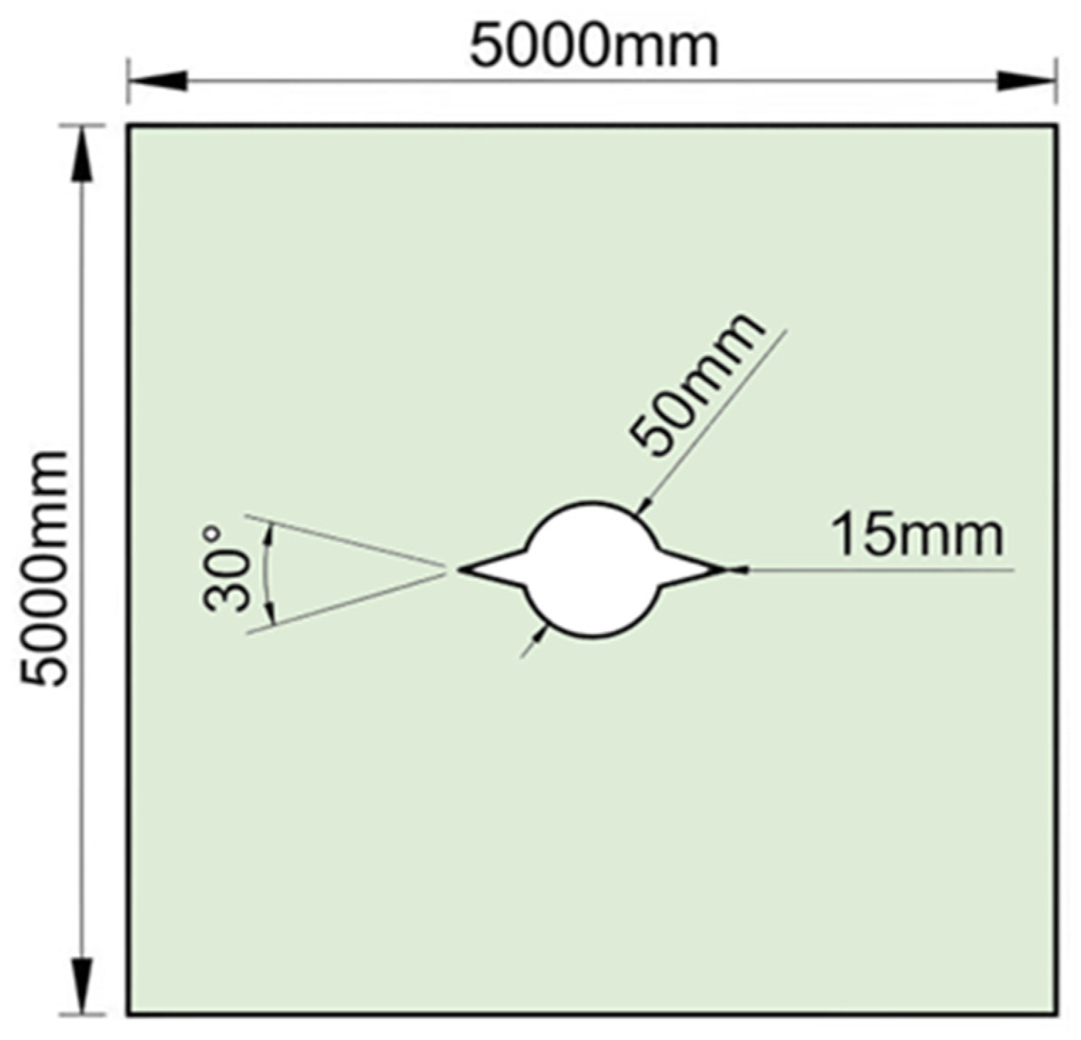
In this study, the problem is simplified to a plane stress problem. This plane stress model represents the middle cross-section of a long blasthole and is mainly used to compare the in-plane crack-guiding effect of different slot angles and hole spacings. Longitudinal stress wave propagation, axial confinement, and end effects along the blasthole are not included in the present two-dimensional model. Figure 1 shows the plan view of the 30° slotted hole, and other angles of slotted holes are constructed in the same way. The model selects a fixed slot depth of 15 mm, takes the slotting angle as a single variable, and sets nine slotting angles with a gradient of 10°; the rest of the parameters are unified, the boundary length is 5000 mm × 5000 mm, the radius of the blasthole is 25 mm, the radius of the explosives is 20 mm, and the length of computation is 500 μs in order to compare the difference in the blasting dynamic response of the slotting holes with different angles.

2.2. Algorithm Selection

In the numerical simulation of explosion problems, with the help of LS-DYNA software 2022R1, it is usually necessary to choose among three types of computational methods [20]: Lagrangian, Eulerian, and coupled Lagrangian–Eulerian algorithms (ALE). The Lagrangian method is prone to suffering from a sudden decrease in computational efficiency and accuracy due to severe mesh distortions and even negative mesh volume values, which ultimately force the computation to be interrupted when dealing with large deformation problems in fluids and gases. In contrast, the Eulerian method, although more cumbersome and inefficient in boundary situations, has the advantage of being able to handle large deformation problems better. The ALE algorithm combines the advantages of the Lagrange and Euler methods, which can effectively deal with the fluid–solid coupling and large deformation problems. As an algorithm to deal with the fluid–solid interaction, it not only supports the self-migration of materials but also successfully overcomes the challenges of mesh deformation and material coupling and realizes the simplification of the setting of boundary conditions. The numerical simulation framework of this study aims to reproduce the diffusion process of explosion-induced shock waves in a gaseous environment covering a wide range of materials, such as gases, explosives, and rocks, and in view of which the ALE algorithm is selected as the most appropriate solution.

2.3. Naturalistic Material Model

In LS-DYNA software, the MAT_JOHNSON_HOLMQUIST_CERAMICS (JH2) model [21] was used to simulate the dynamic properties of the surrounding rock. Based on the specific simulation results and the special properties of sandstone, the HJ2 model is used to describe the sandstone principal relationship, and the HJ2 principal model adopts the damage parameter D to measure the damaged condition of the surrounding rock, while the damage parameter D is determined by assessing the cumulative effect of the equivalent plastic strain and the plastic volumetric deformation. The expression for D [22,23] is
D = Δ ε p ε f p
where Δ ε p is the cumulative integral of the effective plastic strain of the material in one cycle; ε f p is the ultimate plastic strain of the material at hydrostatic pressure.
The physical and mechanical parameters of sandstone used in this study are listed in Table 1. These parameters include density, compressive strength, Young’s modulus, P-wave velocity, and Poisson’s ratio, which can characterize the basic mechanical properties, elastic deformation behavior, and the stress wave propagation capacity of sandstone, as well as provide a basis for the subsequent selection of JH2 material model parameters and blasting dynamic response analysis.
In LS-DYNA, the MAT_HIGH_EXPLOSIVEg_BURN material model [24] and the EOS_JWL [25,26] equation of state are used to simulate the explosives. The JWL equation of state is shown in (2). The JWL equation of state is a semiempirical equation describing the pressure–volume–energy relationship of the detonation products of cohesive explosives, and it is widely used in the simulation of explosion mechanics and hydrodynamics. The JWL equations fit well with the actual explosion situation and can better simulate the expansion process of the blast products and the propagation of the blast wave.
p = A ( 1     ω R 1 V ) e R 1 V + B ( 1     ω R 2 V ) e R 2 V + ω E 0 V
where P is the burst pressure; V is the relative volume; E0 is the initial internal energy density; A, B, R1, R2, and ω are the burst pressure; and e is the specific internal energy, see Table 2 for details (using the international standard unit: SI).
The air material model involved in the coupling medium is uniformly chosen to be constructed with the material-free material model MAT_NULL embedded in the ANSYS/LS-DYNA software 2022R1 package, and its density ρ is set to be 1200 kg/m3, while the rest of the parameters follow the default configurations preset by the system. The equation of state of the air is characterized with the help of a linear polynomial EOS_LINEAR_POLYNOMIAL, which is expressed as follows [27]:
P   =   C 0   +   C 1 μ   +   C 2 μ 2   +   C 3 μ 3   +   ( C 4   +   C 5 μ   +   C 6 μ 2 ) E
where C0, C1, C2, C3, C4, C5, C6 are the input parameters; E is the intercept of the curve between the velocity of the shock wave and the velocity of the mass; air material parameters as shown in Table 3 below (using international standard units: SI).

2.4. Meshing and Boundary Condition Characterization of Blasting Damage in Slotted and Round Holes

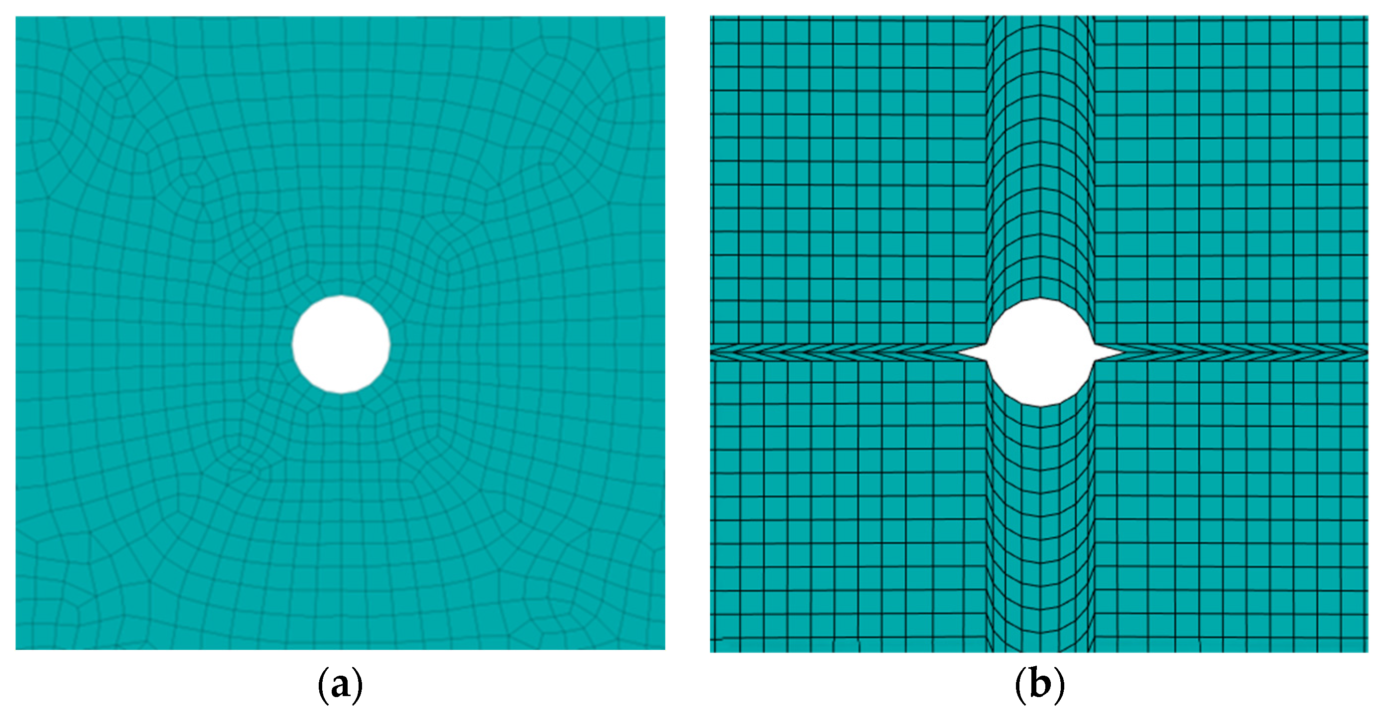
The grid is divided as shown in Figure 2a,b, which are the schematic diagrams of the grid division of the circular blastholes and the slotted hole, respectively. The grid division has been refined, and the encrypted grids are used around the periphery of the blastholes and the slotted area to enhance the calculation accuracy and avoid the negative volume phenomenon. The boundary conditions are set as non-reflective mode [28,29] to ensure the free propagation of stress waves. Fluid–solid coupling is adopted on the contact surface between explosives and rock, and the fluid area covers the blasting range to simulate the real working conditions.

3. Simulation Analysis Results

3.1. Characterization of Blasting Damage in Slotted and Circular Holes

In order to reveal the influence of the V-shaped slotted structure on the blasting stress field and crack extension behavior, a conventional circular shell hole and a V-shaped slotted shell hole were selected for comparative analysis.
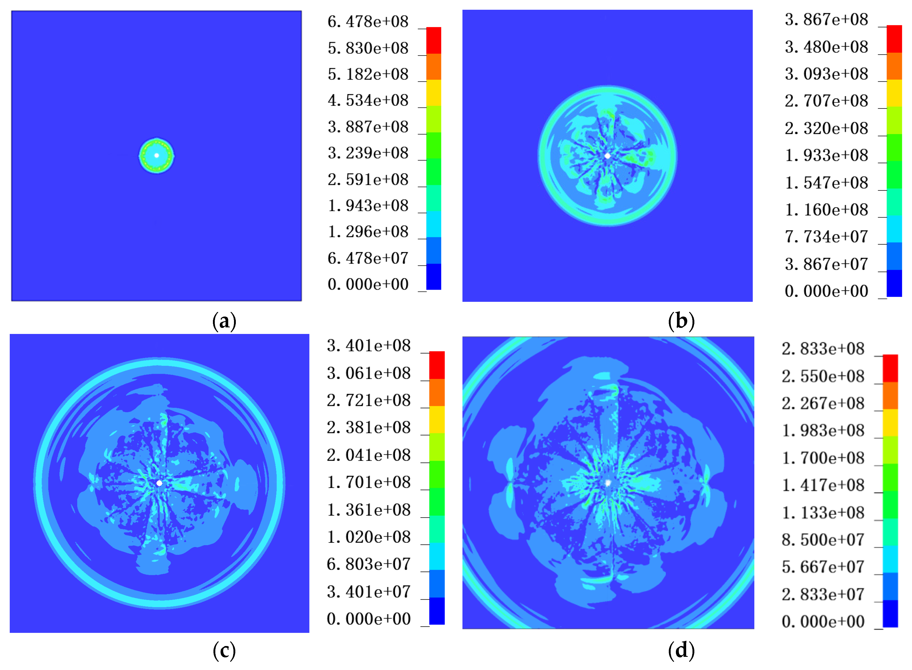
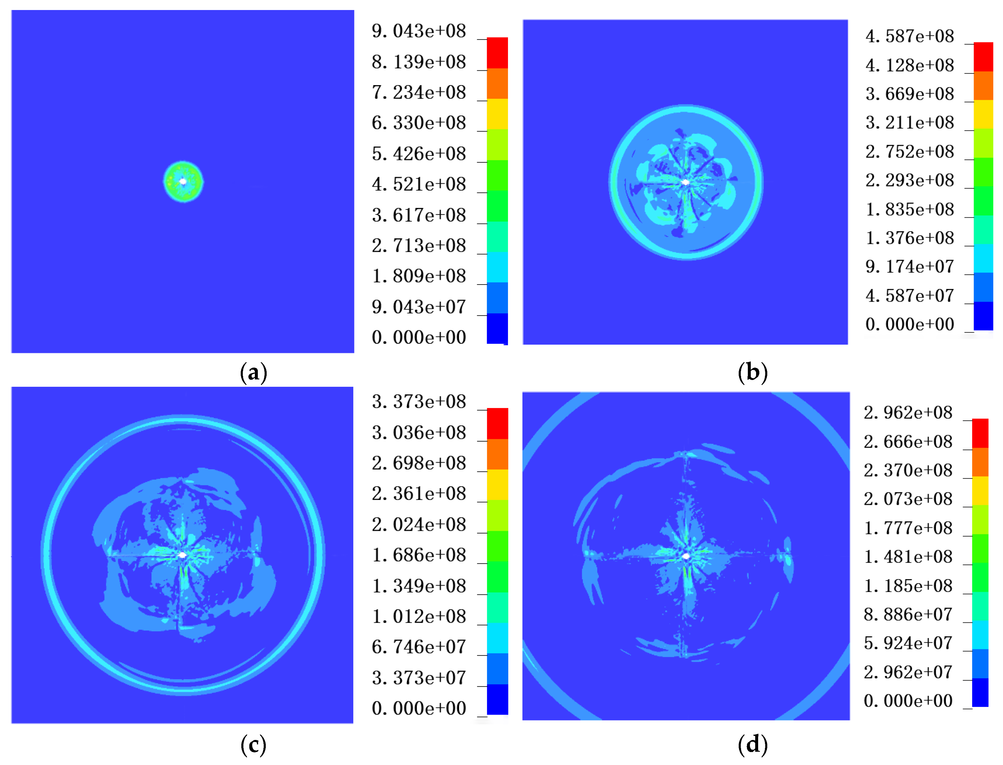
Figure 3 shows the effective stress cloud during the blasting of a conventional circular hole. Calculation results show that at 50 μs, the explosive gas and shock wave generated by the detonation of explosives rapidly act on the wall of the blasthole. Due to the better geometric symmetry of the circular hole, the hole wall is more uniform in all directions, the stress wave spreads outward with an approximate circular wave front, and the peak effective stress at this time is about 0.62–0.69 GPa. With the time advancing to 200 μs, the stress wave continues to propagate to the interior of the rock body, and the range of the wave front is expanding, and the shock wave is gradually attenuated and converted into a stress wave. At this time, the stress distribution inside the rock body still maintains the obvious cyclic characteristics, and the peak effective stress decreases to about 0.35–0.39 GPa, indicating that the energy of the stress wave gradually decays with the increase in the propagation distance. At 350 μs, the stress wave has been propagated to a larger range of the model; there is still a certain stress concentration near the hole, but the peak value has been further reduced, and the effective stress near the hole wall extreme has a value of about 0.34 GPa. At the 500 μs time step, the stress wave basically propagated to the model boundary, and in the absence of the reflection of the boundary effect is absorbed. There is no obvious reflection interference. On the whole, the blasting stress field of the circular blasthole is more uniformly distributed, and the damage zone is extended outward in an approximate circle, and the cracks are developed in multiple directions without showing obvious dominant extension directions.
Figure 4 shows the effective stress cloud during blasting of a 60° V-shaped slotted blasthole. Unlike a circular blasthole, the V-shaped slotted structure changes the way the explosive load acts around the hole wall. In the 50–200 μs stage, the shock wave formed after the detonation of explosives first acts on the wall of the borehole and propagates along the contour of the borehole. Due to the geometric mutation of the slotting tip, the local stress is concentrated at the end of the slot, and an obvious high stress zone is gradually formed in the region of the slotting tip on both sides of the borehole. This phenomenon indicates that the slot structure can change the propagation path of the explosive stress wave, so that the blast energy is preferentially converged to the vicinity of the slot tip. At 350 μs, the blast gas and stress waves act together on the hole wall and adjacent rock, and the stress concentration at the tip of the slot further promotes the development of local damage, meaning cracks begin to expand along the slot direction. At 500 μs, the stress wave propagates to the boundary of the model and is absorbed, and the crack expansion of the rock body is basically completed. At this time, the damage pattern around the notched hole has changed from the approximate circular distribution in the round hole blasting to the “zigzag” feature along the direction of the slot and its normal expansion, indicating that the V-shaped slot has an obvious guiding effect on the crack expansion.
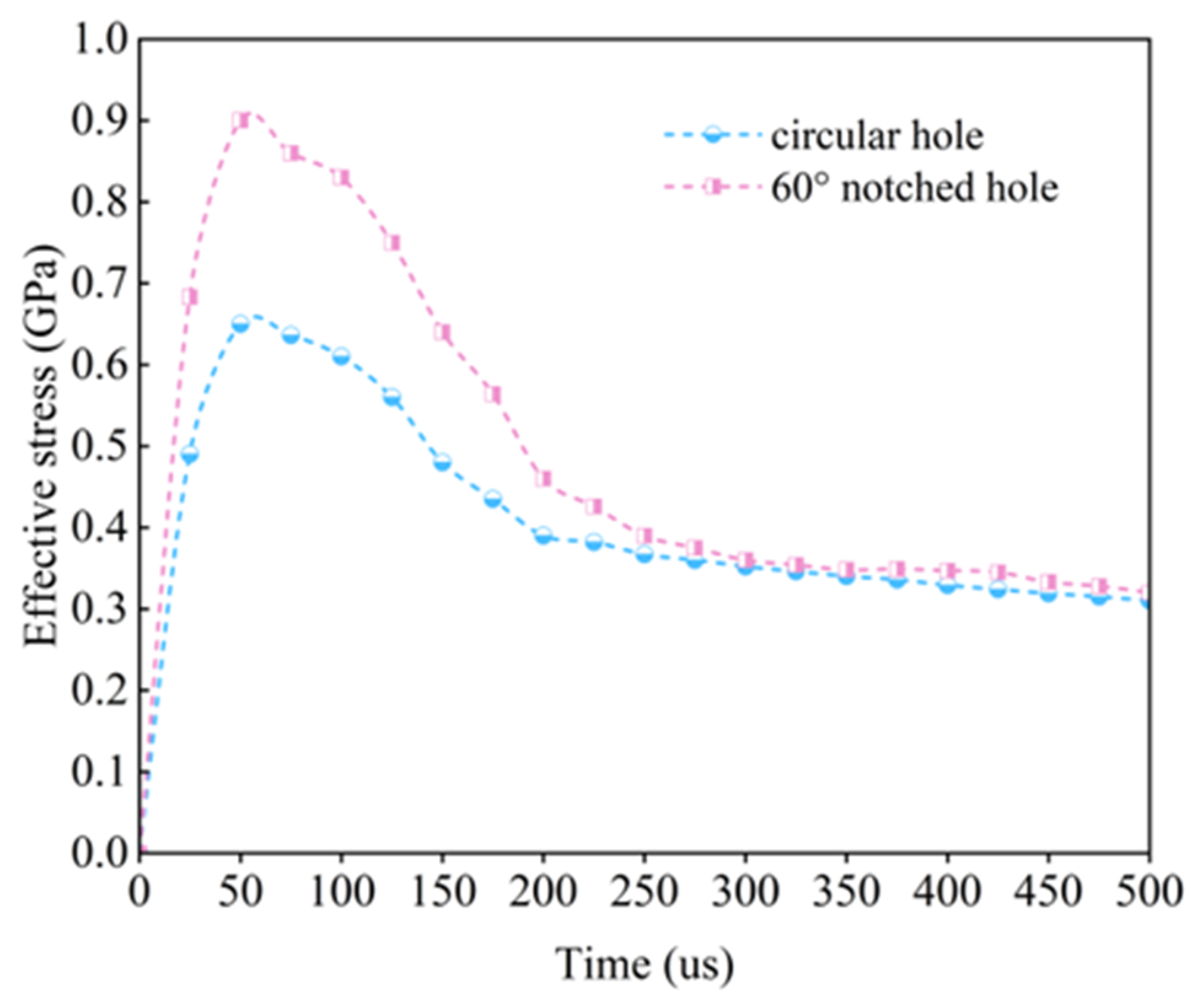
Circular blastholes due to the hole wall geometry are continuous, smooth, and the curvature in all directions is basically the same. The explosion stress wave and the role of explosive gas on the hole wall are more uniform. Therefore, circular blastholes in the process of blasting stress waves mainly in the approximate circular wave front propagate outward, and the rock damage zone as a whole presents a strong isotropic characteristic. In contrast, due to the obvious geometric mutation at the slot tip, the explosion load is locally concentrated at the end of the slot, which makes it easier to reach the dynamic rock damage conditions in the direction of the slot and its neighboring areas, thus inducing the cracks to preferentially expand along the predetermined direction, and the peak effective stress is approximately 30% higher than that in circular boreholes (Figure 5). In the present model, the detonation process was described by the MAT_HIGH_EXPLOSIVE_BURN material model and the JWL equation of state with a fixed explosive parameter set. Therefore, the reported increase in peak effective stress reflects the response under the selected detonation velocity and charge structure. A higher detonation velocity may further increase the local pressure at the slot tip, but it may also enlarge the crushed zone near the blasthole before stable directional cracks are formed.

3.2. Effect of Slot Angle on the Evolution of the Blasting Stress Field

From the previous conclusions, it is known that the slotted holes have significant advantages over the circular holes, so it is crucial to determine the optimal angle of the slotted holes. In this study, nine slot-angle cases were considered, including one circular-hole case (0°) and eight V-shaped slotted-hole cases with slot angles ranging from 10° to 80° at intervals of 10°. For each slot angle, the evolution of the effective stress field was monitored throughout the blasting process. Representative stress wave distributions at 50 μs, 200 μs, and 350 μs were selected for comparison to evaluate the influence of slot angle on stress concentration and crack-guiding behavior.
Nine slot-angle cases were considered, including the circular hole case of 0° and V-shaped slotted holes from 10° to 80° at an interval of 10°. For each case, the effective stress evolution was extracted within 0–500 μs, and representative stress wave patterns between 50 and 350 μs were compared.
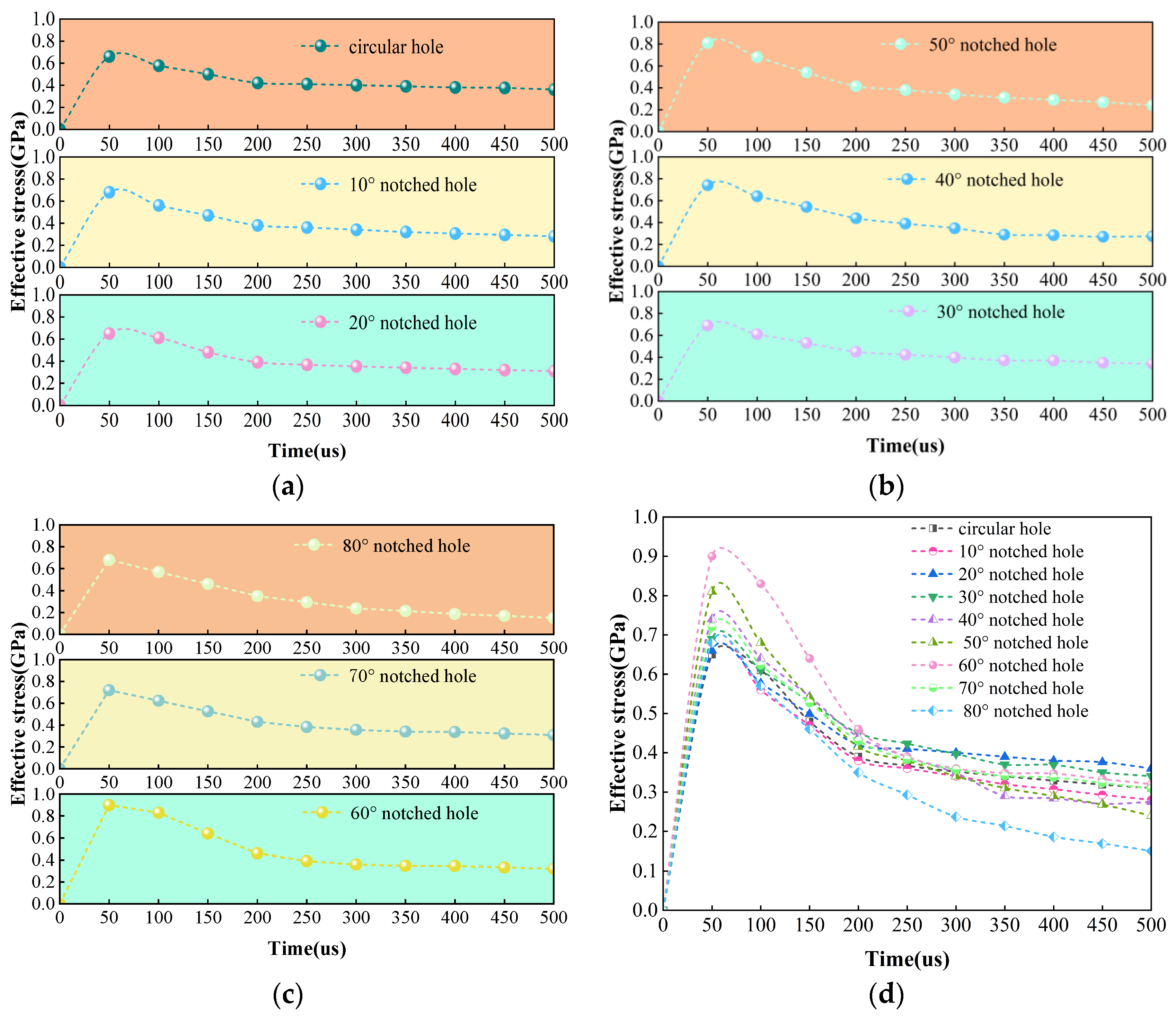
At 50 μs, the explosive is in the initial stage of detonation, and the effective stress reaches its peak, as shown in Figure 6. The time–history curves of effective stress for various slot angles indicate that, within an acceptable range of simulation error, the peak effective stress first increases and then decreases as the slot angle increases, following an inverted U-shaped trend. When the slot angle is 60°, the peak stress is 0.91 GPa, which is the maximum value across the entire range of angles. Within the range of 40–70°, the peak effective stress differs significantly from that at other angles, ranging from 0.74 GPa to 0.91 GPa; thereafter, the peak stress gradually decreases. Simulation results indicate that the slotted angle has a significant effect on the degree of stress concentration during the initial stage of the blast. As the slot angle gradually increases from a smaller angle, the peak effective stress near the slot tip gradually rises, suggesting that appropriately increasing the slot angle helps enhance the concentration of the explosive load in the slotted tip region. When the slot angle increases to approximately 60°, stress concentration at the slotted tip is most pronounced, with the peak effective stress reaching its maximum value across all operating conditions. However, continuing to increase the slot angle causes the peak effective stress to decrease, indicating that an excessively large slot angle weakens the energy-concentrating effect at the slot tip, causing the explosive energy to disperse over a larger cavity area.
From the point of view of the stress wave propagation pattern, there are obvious differences in the stress distribution around the hole at different slot angles. A small-angle slotted hole in the propagation direction of the stress wave change is weak, and the stress wave is still in the form of an approximate circular outward diffusion; the stress field around the hole and the conventional circular hole blasting are relatively close. As the slot angle increases, the stress wave morphology gradually changes from an approximate circular distribution to an elongated oval or band distribution along the direction of the slotting, indicating that the slot structure begins to significantly change the propagation path of the explosive energy, so that the energy is concentrated in the direction of the slotting concentration release. Especially in 60° slot angle conditions, the slotting direction and its normal region have a strong stress response, and the stress field around the hole presents a more obvious “zigzag” concentrated distribution, indicating that the angle of the stress concentration area and the direction of the subsequent crack extension have a better consistency.
A comparison of different slot angles under the peak effective stress and stress wave morphology evolution law can be seen; the slot angle is not larger or more conducive to directional blasting, but the tip stress concentration and directional release of energy achieve a better balance at a reasonable angle. When the slot angle is too small, the slot on the hole around the stress field disturbance is insufficient and difficult to effectively induce crack expansion along the target direction; when the slot angle is too large, the slot cavity volume increases, the tip of the energy concentration effect is weakened, and blasting energy dispersion occurs. In contrast, the 60° slot angle can maintain a strong tip stress concentration while making the stress wave propagate effectively along the slotting direction, thus showing the optimal stress concentration effect. Therefore, based on the effective stress peak and stress wave propagation pattern analysis, 60° can be used as a better grooving angle for directional blasting of V-shaped slotted blastholes under the model conditions in this paper.

3.3. Influence of Slot Angle on Crack Extension and Crack Control Effects

In order to further evaluate the effect of crack extension under different slot angles, the crack control index is introduced as a quantitative evaluation index in this paper. The crack control index is defined as the ratio of the maximum damage depth in the slotting direction to the maximum damage depth in the non-slotting direction and perpendicular to the slotted direction, which can be expressed as follows:
C C I = L S L P
where CCI is the crack control index, the maximum damage depth in the slotting direction, the maximum damage depth in the non-slotting direction, and is perpendicular to the slotting direction.
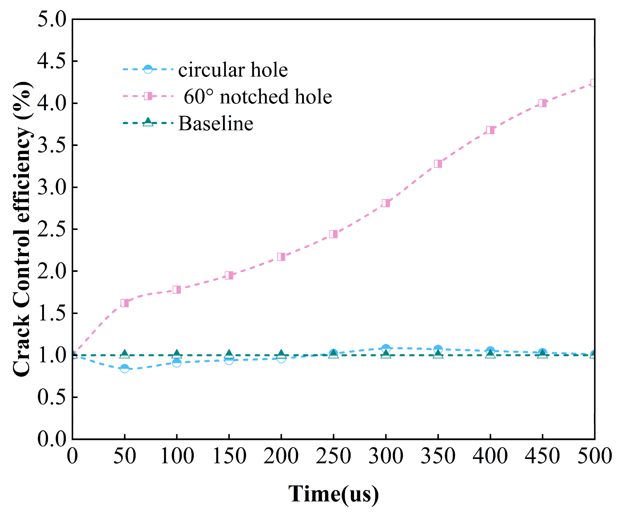
The larger the crack control effect coefficient, the better the crack extension effect of the slotted angle. In conventional circular single-hole blasting, due to the uniform distribution of damage in all directions, the damage control index is roughly equal to 1. For V-shaped slotted blastholes, if the slot has a good guiding effect, the crack length in the target direction is significantly larger than that in the non-target direction, and the crack control index increases accordingly. It can also be seen from Figure 7 that the crack control effect index of the slotted corner is increased by 320% compared to the circular hole. This increase in the crack control index was obtained under the present homogeneous and isotropic sandstone model. In natural sandstone with bedding planes or weak interlayers, blast-induced cracks may be captured or deflected by these structural planes, and the crack control index may therefore be lower than the value obtained in the idealized model.
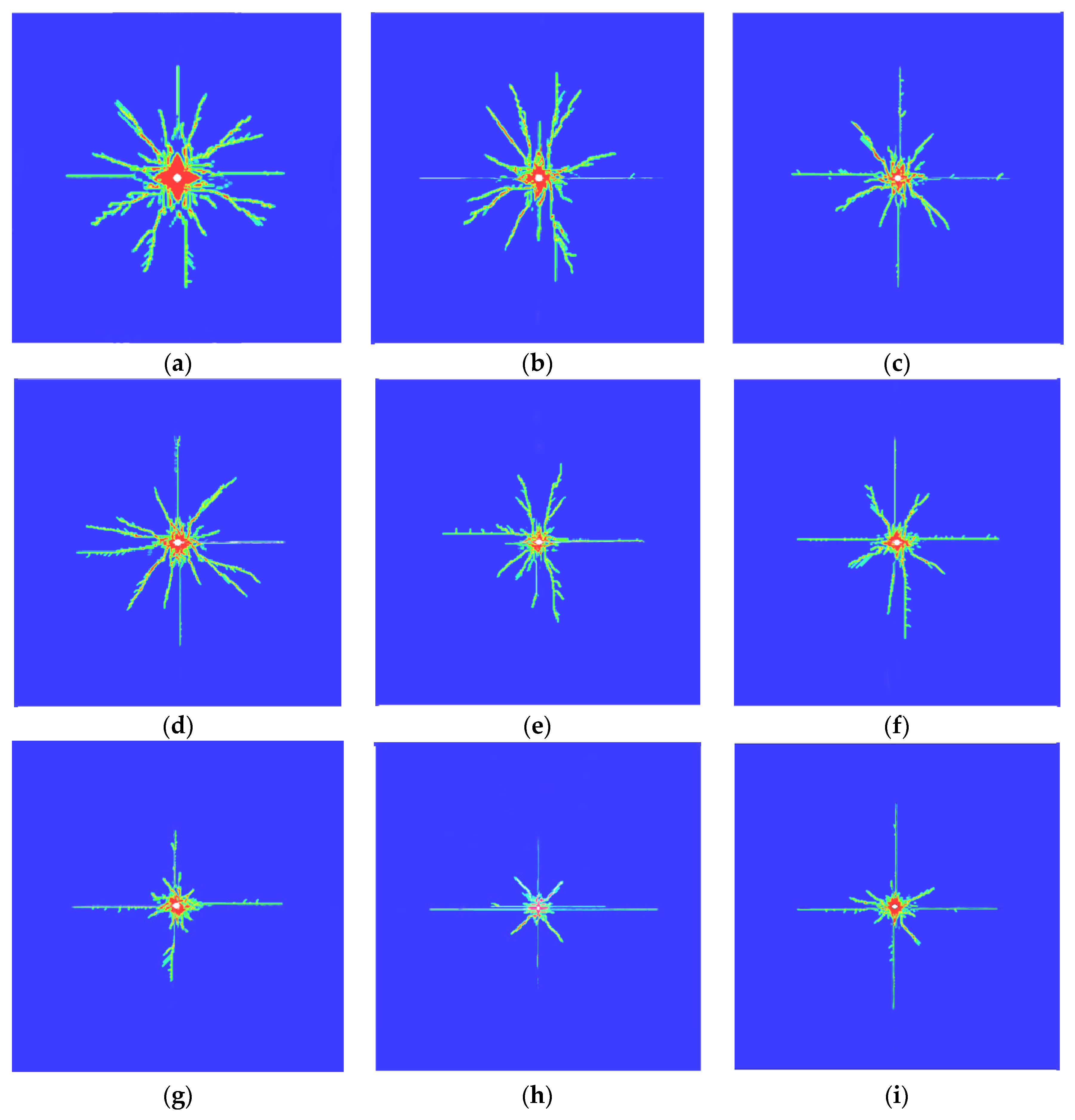
The crack expansion patterns under different slot angles show that the slot angle has a significant effect on the crack initiation location, expansion direction, and final damage distribution (Figure 8). Under the condition of a small slot angle, although the slot tip can induce a certain local stress concentration, its ability to constrain the crack expansion path is weak, and the cracks may still expand in multiple directions, and the directionality is not obvious enough. With the increase in the slot angle, the crack length in the slotting direction gradually increases, the non-target direction cracks are suppressed, and the crack distribution gradually changes from irregular expansion to directional expansion along the slotting direction and its normal direction. When the slot angle is 60°, the crack extension direction is the most clear, the crack length in the target direction is larger, the crack in the non-target direction is relatively shorter, and the overall crack morphology is obviously distributed in the shape of a “zigzag”. This phenomenon shows that under the condition of a 60° slot angle, the explosion energy can be more concentrated in the slot tip area and induce stable crack expansion along the slotting direction.
The variation rule of the crack control index with the slot angle is basically the same as that of the peak effective stress, i.e., it reaches the maximum value near 60°. This indicates that there is a good correspondence between the peak effective stress and the crack control index: the higher tip stress concentration is favorable for the preferential crack initiation and expansion in the target direction, while a reasonable slotted angle can enhance the stress concentration and crack guidance at the same time. Combining the effective stress distribution, crack expansion pattern, and crack control index, 60° can be taken as a better slot angle for V-shaped slotted directional blasting in sandstone under the simulation conditions in this paper. In order to verify the accuracy of the simulation results, the theoretical analysis will be carried out in the next section and compared with the simulation results.

3.4. Theoretical Derivation of Optimal Slot Angle

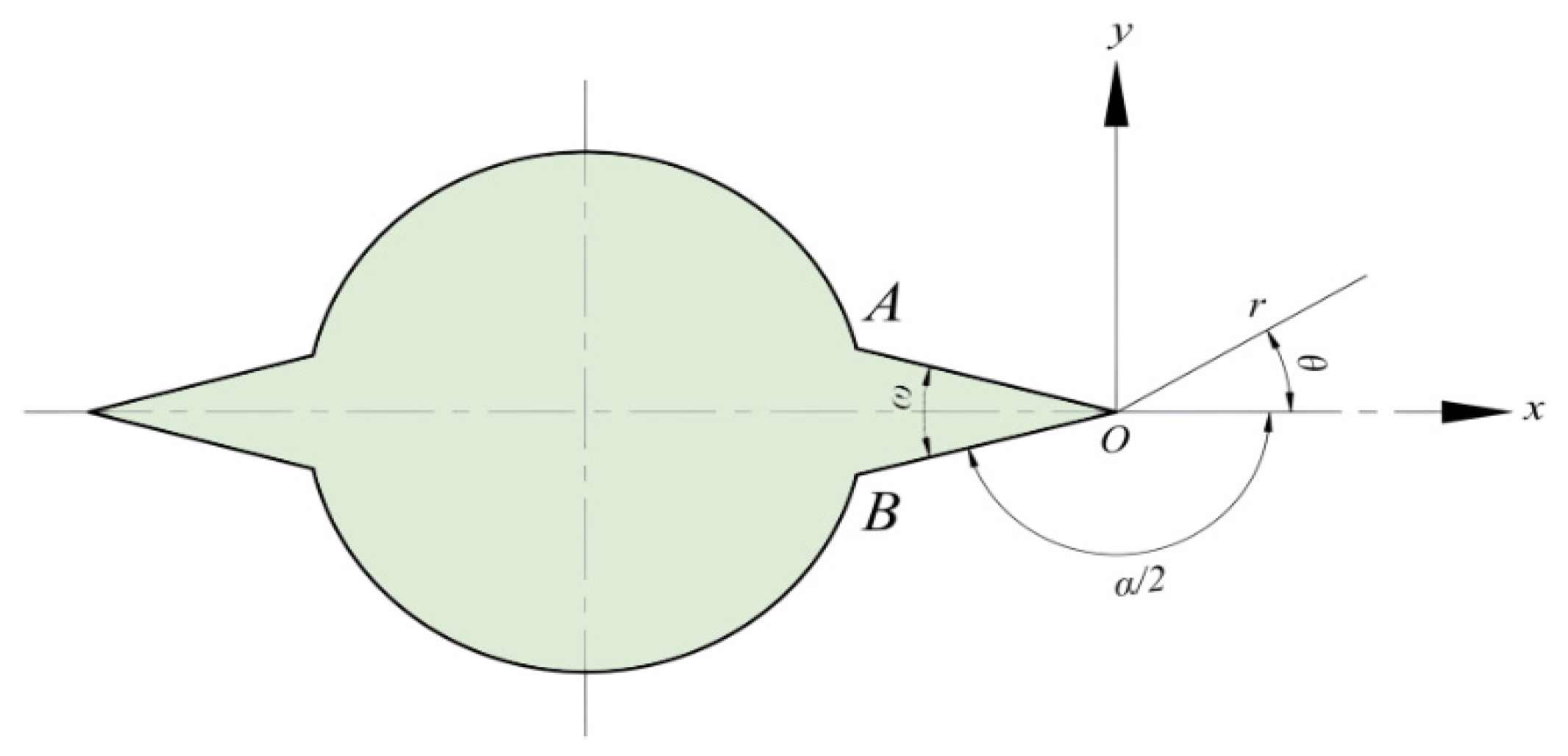
In simulation experiments and practical engineering, the results may deviate from the theoretical optimum angle, so the optimum V-shaped slotted blasthole angle is determined with the help of the tip stress field equation. As shown in Figure 9, a polar coordinate system (θ, r) with the slot tip as the origin and a right-angle coordinate system (xoy) are established, where ω is the slot angle.
Qingtong Wei [30] has systematically studied the elastic–plastic stress-displacement field at the tip of a V-shaped incision under plane loading conditions and proposed an analytical solution based on power series expansion [31]. Considering the brittle characteristics of rock materials, this study adopts the classical calculation model in the literature to construct the mathematical expression of the stress field at the tip. In order to analyze the stress concentration characteristics at the tip of the incision, based on Wei Qingtong’s model, the stress component can be expressed as follows:
σ x x   =   n = 1 S n r S n 1 { a s n 2 ( ( 3     ( S n   +   1 ) A n ) cos ( S n     1 ) θ     ( S n     1 ) cos ( S n     3 ) θ ) + b s n 2 ( ( 2     B n ( 1   +   S n ) ) sin ( S n 1 ) θ     ( S n     1 ) cos ( S n     3 ) θ ) }
σ y y = n = 1 S n r S n 1 { a s n 2 ( ( 2 + ( S n + 1 ) A n ) cos ( S n     1 ) θ + ( S n     1 ) cos ( S n     3 ) θ ) + b s n 2 ( ( 2 + B n ( 1 + S n ) ) sin ( S n     1 ) θ     ( S n     1 ) sin ( S n     3 ) θ ) }
where σ x x , σ y y , are the stress values in the x and y directions, respectively; as12, is the boundary influence coefficient; An, Bn are the coefficients of the stress field distribution; and Sn is the characteristic root of the power series expansion.
In order to find the optimal slot angle, it is especially critical to solve Sn. The correct form of the characteristic equation in the theory of the stress field at the tip of the V-shaped slot is:
sin S n + 1 2 α     m sin S n 1 2 α = 0
where m is a coefficient related to the boundary conditions, collapsed to give:
m = sin S n + 1 2 α sin S n 1 2 α
S1, S2, …, Sn, …, are all possible solutions greater than 0 under any given 0 < S1 < S2 … < Sn < …. This equation defines the relationship between the characteristic root Sn and the angle. The smallest positive characteristic root S1 is the most important and dominates the stress concentration at the tip of the slotted cutting. When finding S1, the two ends of the equation about the derivatives, after finishing, can be obtained:
d m d α = S n + 1 2 cos S n + 1 2 α · sin S n 1 2 α S n 1 2 cos S n 1 2 α   · sin S n + 1 2 α sin 2 S n 1 2 α
When d m d α = 0, there is an extreme value relationship between m and α . At this point, S1 = 1, and bringing S1 = 1 into the stress components of X and Y yields:
σ x x = a s n 2 3 2 A 1 ,   σ y y = a s n 2 2 + 2 A 1
When σ yy / σ xx is the largest value, it indicates that the directional stress concentration effect at the slotted tip is the strongest at this time. To determine the value of σ yy / σ xx , it is crucial to calculate A1. According to the derivation of the slotted theory, the actual formula of A1 is:
A n = cos S n 1 2 α cos S n + 1 2 α
Based on the practical requirements for slotted blasting, when the slot angle is set to 30°, 45°, and 60°, the values of A1 are calculated. Substituting the values of A1 into the calculation, the resulting values of σ y y / σ x x are 0.058, 0.142, and 0.286, respectively. For specific data, see Table 4. Based on the calculation results, when the slot angle is 60°, σ y y / σ x x is maximized, meaning that the tensile stress perpendicular to the X direction is greatest during blasting. Therefore, it can be concluded that when using boreholes with a V-shaped slot, the blast crack will propagate along the line connecting the tips of the V-shaped slot, thereby achieving the objective of directional blasting. Additionally, the best fracture results are obtained when the slotted angle is 60°.
According to the definition of the strength factor K [32]:
K = 2 π S 1 1 + S 1 1 + A 1 a s 12
Let k   =   S 1 1   +   S 1 1   +   A 1 then
K = 2 π k a s 12
In this theoretical derivation, K is defined as a slotted angle influence factor under the idealized V-shaped slot tip stress field assumption. It mainly reflects the geometric contribution of the slot angle to tip stress concentration. The effects of in situ ground stress, bedding planes, and three-dimensional confinement are not included in this factor. Therefore, the 60° slot angle obtained from the theoretical derivation should be regarded as the optimal geometric angle under the present assumptions.
When the slot angle is 30°, 45°, or 60°, the value of k is 0.309, 0.828, and 2, respectively. Thus, it can be seen that k 60 ° is the highest, k 45 ° is the next highest, and k 30 ° is the lowest. For sandstone, the higher the value of k, the easier it is for the rock to fracture. Therefore, it can be concluded that a slot angle of 60° yields the best fracturing results.
Based on the theoretical analytical solution of the stress field at the tip of a V-shaped slot, this section systematically analyzes, through mathematical derivation, the influence of the slot angle on the stress distribution at the tip of the blasting hole and the crack initiation efficiency, with the aim of determining the optimal slot angle to achieve the best directional fracture effect. By combining stress field analysis with fracture mechanics strength criteria, this study theoretically confirms that for V-slotted blastholes, when the slot angle is 60°, it most effectively induces and controls the directional propagation of blast cracks, thereby achieving optimal fracture performance.

3.5. Optimization of Hole Spacing and Analysis of Crack Propagation in V-Shaped Double-Hole Slotted Blasting

In actual tunnel excavation, mining operations, and underground engineering projects, blasting typically employs a multi-hole configuration. Whether effective cracks can form and propagate through the rock mass between holes directly affects the quality of rock fragmentation, the effectiveness of excavation contour control, and the efficiency of blasting energy utilization. Single-hole blasting primarily reflects the characteristics of stress wave propagation and crack propagation around a single hole. In contrast, in double-hole blasting, there is a significant stress wave superposition effect between the two holes, and the failure behavior of the rock bridge between them is more complex. For V-shaped slotted blastholes, inter-hole crack propagation depends not only on the superposition of the blast stress waves from the two holes but is also influenced by the guiding effect of the slot structure on the direction of crack propagation. After identifying 60° as the optimal slot angle under the single-hole conditions, this angle was adopted in the double-hole model to further investigate the influence of hole spacing on inter-hole crack propagation. In these simulations, the two blastholes were initiated simultaneously so that the effects of hole spacing, inter-hole stress wave superposition, and V-shaped slot guidance could be isolated under controlled conditions. Therefore, the hole-spacing results discussed below should be interpreted as those obtained under the synchronized initiation condition.
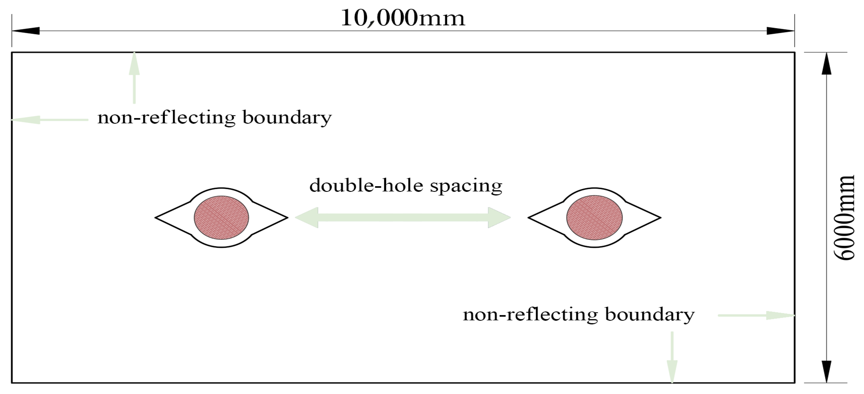
In order to determine a reasonable slotting hole spacing, a conventional circular double-hole model and a V-shaped slotting double-hole model are established to compare and analyze the characteristics of blasting crack expansion under different hole-spacing conditions. The model consists of three parts: rock body, explosives, and air, and the overall size is 10,000 mm × 6000 mm, as shown in Figure 10. Non-reflective boundaries are set around the model to minimize the influence of the reflection of stress waves at the boundaries on the calculation results. The rock body is simulated by a solid unit, and the explosives and air are simulated by a fluid unit. The fluid–solid coupling between the explosion products, air, and rock body is processed based on the ALE algorithm. The selected hole spacing of 50–130 cm covers three typical working conditions: excessive crushing at small spacing, effective penetration at medium spacing, and difficult penetration at large spacing, which are taken as 50 cm, 70 cm, 90 cm, 110 cm and 130 cm, respectively, and the forms of the holes include conventional round holes and 60° V-shaped slotted blastholes, with a total of 10 calculation conditions. In order to ensure the comparability between different working conditions, dimensions of the holes, the charging structure, the material parameters, the uncoupling coefficient, and the boundary conditions are consistent in each model, and the uncoupling coefficient is taken as 2.5.
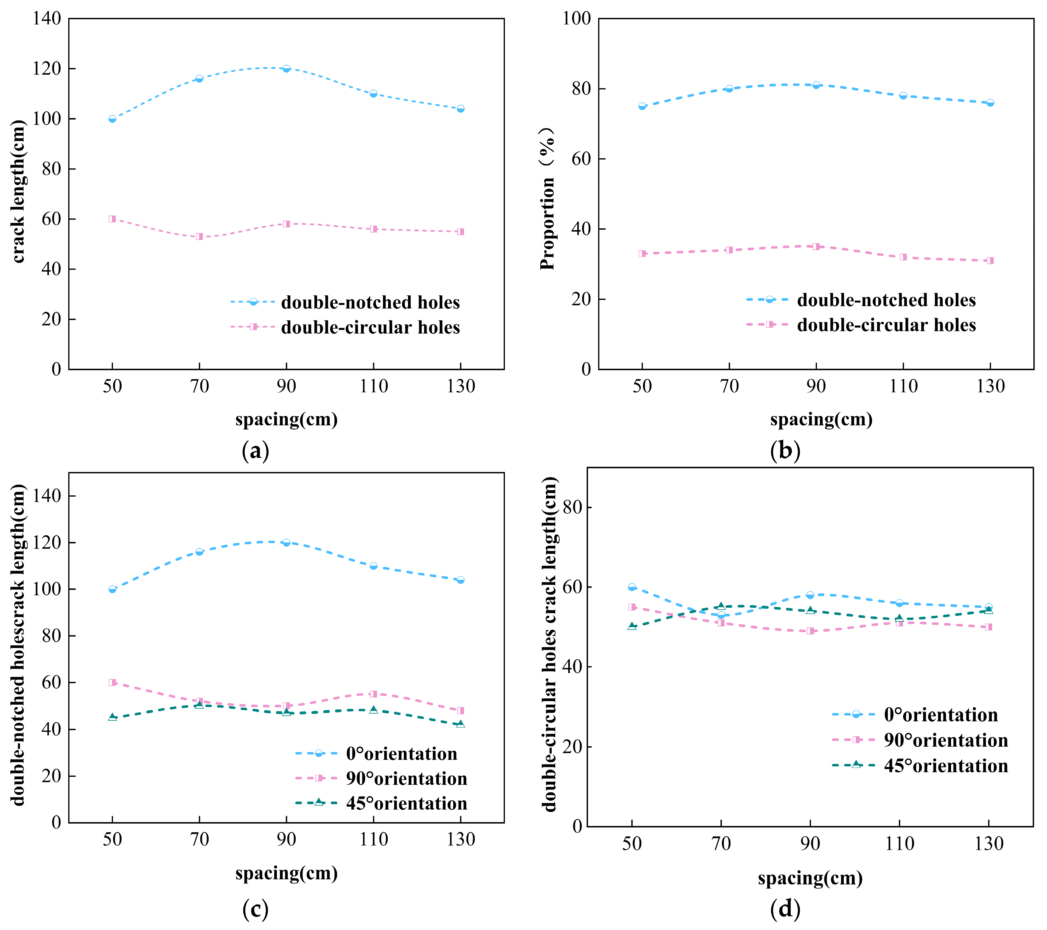
Figure 11 demonstrates the crack extension results of conventional circular double holes and V-shaped slotted double holes under different hole-spacing conditions. In order to quantitatively evaluate the directional expansion effect of cracks between holes, this paper defines the cracks expanding along the direction of the slot, i.e., the 0° orientation in the direction of the connecting line of the two holes, as the effective excavation cracks, and those expanding in the other directions as the ineffective cracks. The simulation results show that the crack length of the V-shaped slotted twin holes in the 0° direction is significantly larger than that in the non-slotted direction (Figure 11a), indicating that the slot structure can effectively induce cracks to expand to the inter-hole region. In contrast, the cracks in conventional circular double-hole blasting are mostly radially expanded in all directions from the holes; the overall distribution is more uniform (Figure 11d), the lack of an obvious dominant direction, and the inter-hole crack penetration mainly relies on the role of the superposition of stress waves, and the direction of the control ability is weaker.
In terms of crack length and effective crack ratio, a V-shaped slotted twin-hole blasting shows better crack guidance than conventional circular twin holes at different hole spacings (Figure 11c). When the hole spacing is 50 cm, the distance between the two holes is small, the superposition of stress waves is strong, the rock between the holes is easily damaged, and the cracks are able to connect the two holes faster. However, a hole spacing that is too small will lead to more serious crushing damage of the rock bridge between the holes, and a large amount of explosion energy will be consumed in the local crushing zone, which is not conducive to the formation of stable and clear directional cracks. Therefore, although the inter-hole damage is more obvious in the 50 cm case, the damage form is closer to local over-crushing, and the crack orientation and energy utilization efficiency are not optimal.
When the hole spacing is increased to 70–90 cm, the V-shaped slotted double holes show a better crack penetration effect. In this range, the explosion stress wave propagated to the inter-hole area still has enough strength to form effective tensile stress superposition in the rock bridge between the holes; at the same time, the stress concentration at the tip of the slotted guides the cracks to expand stably along the connecting direction of the two holes, so that the cracks in the inter-hole area are gradually penetrated. The simulation results show that the cracks in this spacing range are mainly concentrated between the two holes, the continuity of the damage zone between the holes is strong, and the effective crack length in the 0° direction is larger, and the proportion of effective cracks can be up to about 80% (Figure 11b). This indicates that the 70–90 cm hole spacing can better balance the superposition strength of the stress wave and the guiding effect of the slot, which is a more reasonable range of double-hole spacing under the model conditions of this paper.
When the distance between the holes was further increased to 110–130 cm, the effect of crack penetration between the holes decreased significantly. As the distance between the two holes increases, the explosion stress wave attenuates in the propagation process, and the stress amplitude decreases when it is transmitted to the inter-hole region, and the superposition of tensile stress between the two holes is not enough to continuously drive the crack expansion. At this time, the cracks are mainly developed in the vicinity of the respective holes, the damage zone between the holes is gradually reduced, and the crack expansion pattern tends to be similar to the results of two independent single-hole blastings. Especially in the 130 cm hole spacing, the synergistic effect between the two holes is significantly weakened, and it is difficult to form an effective penetration of the cracks between the holes. For the conventional circular two-hole blasting, there is also the phenomenon of weakening the role of the two holes after increasing the hole spacing, but due to the lack of slotted guiding, the cracks under different spacing are still mainly multi-directional diffusion, and the advantage of target-directed cracks is not obvious.
When there is a comprehensive different hole spacing under the crack length, the proportion of effective cracks and the inter-hole damage penetration pattern can be seen. Two-hole V-shaped slotted blasting hole spacing is neither smaller, better, nor larger; it is not favorable. When the hole spacing is too small, the rock between the holes is easily over-crushed, reducing the efficiency of blasting energy utilization; when the hole spacing is too large, the stress wave attenuation is obvious, and it is difficult to penetrate the inter-hole cracks. The 70–90 cm hole spacing can ensure the effective superposition of inter-hole stresses while giving full play to the guiding effect of the V-shaped slot on the crack expansion path, so that the effective cracks are concentrated in the direction of the two holes. Therefore, under the model parameters and sandstone material conditions of this study, the 70–90 cm spacing, namely the ratio of hole spacing to blasthole diameter of approximately 14–18, can be regarded as a reasonable baseline range for 60° V-shaped slotted double-hole blasting under simultaneous initiation. In actual engineering applications, especially when millisecond delay blasting is adopted, the first blasthole may generate a pre-fractured zone, stress release region, and stress shadow before the subsequent blasthole is initiated. Therefore, the hole spacing should be further modified and optimized by considering delay time, rock strength, hole diameter, charge structure, slot depth, in situ ground stress, and excavation profile requirements.


4. Discussion and Conclusions

In this paper, LS-DYNA was used to establish numerical models of sandstone circular and V-shaped slotted blasting. Based on the ALE fluid–solid coupling algorithm, the effects of slot angle on the blasting stress field, crack propagation pattern, and crack control effect were analyzed. The stress field theory at the tip of the V-shaped slot was further used to explain the mechanical mechanism of the optimal slot angle. On this basis, the influence of hole spacing on inter-hole crack penetration in double-hole V-shaped slotted blasting was investigated. The main conclusions and engineering implications are as follows.
(1) The V-shaped slot structure can significantly improve the directionality of blasting cracks. In conventional circular hole blasting, the stress wave propagates uniformly outward along the hole wall, and the crack propagation direction is relatively dispersed, showing obvious isotropic damage characteristics. In contrast, due to the geometric mutation at the slot tip, V-shaped slotted blastholes form obvious local stress concentrations, which cause cracks to preferentially propagate along the slot direction and its normal direction. Therefore, the V-shaped slot can effectively control the propagation path of blast-induced cracks under the present model conditions.
(2) Under the two-dimensional homogeneous sandstone model adopted in this study, the 60° slot angle is an optimal angle for directional blasting of sandstone V-shaped slotted blastholes. When the slot angle is 60°, the peak effective stress at the slot tip is the largest, the crack control index is the highest, and the crack pattern shows an obvious “zigzag” directional propagation. This indicates that the 60° slot angle can more effectively induce crack initiation and propagation along the target direction, thereby improving the directional blasting effect. However, this result should be understood as the optimal geometric angle under the present simulation conditions rather than a universal field parameter.
(3) The tip stress field theory can explain the mechanical advantage of the 60° slot angle. The theoretical analysis shows that the slot angle changes the stress concentration state in the tip region, and the 60° slot angle corresponds to a stronger tip tensile stress concentration capacity, which is conducive to the tensile damage of sandstone along the slot direction. The theoretical results are basically consistent with the numerical trends of the peak effective stress and the crack control index. It should be noted that the slotted angle influence factor k in the theoretical derivation mainly reflects the geometric effect of the V-shaped slot and does not include the influence of in situ ground stress, bedding planes, or three-dimensional confinement.
(4) In the synchronized two-hole V-shaped slotted blasting model, hole spacing has a significant effect on crack penetration. Under the model parameters and sandstone material conditions used in this paper, when the hole spacing is 70–90 cm, namely the ratio of hole spacing to blasthole diameter is about 14–18, the stress wave superposition between holes and the guiding effect of the slot are more coordinated, and the proportion of effective cracks along the slot direction can reach about 80%. Therefore, the 70–90 cm spacing can be regarded as a reasonable baseline range for synchronized double-hole V-shaped slotted blasting. When millisecond delay blasting is adopted, the first blasthole may form a pre-fractured zone, stress release region, and stress shadow before the subsequent blasthole is initiated, so the optimal hole spacing may shift and should be further modified according to delay time and field conditions.
This paper is based on a two-dimensional homogeneous sandstone model and mainly focuses on the early blasting response within 500 μs, which is suitable for analyzing stress wave propagation, explosion gas action, and initial crack guidance under instantaneous initiation. However, the model has not fully considered in situ ground stress, natural joints, bedding anisotropy, groundwater, multi-hole delayed initiation, charge structure changes, and on-site construction disturbances. If the maximum principal stress is consistent with the slot direction, the guiding effect of the V-shaped slot may be strengthened; if the principal stress direction or bedding plane is oblique to the slot direction, cracks may deviate from the preset direction. Therefore, the 60° slot angle and 70–90 cm hole spacing proposed in this paper should be regarded as numerical reference values under the current model conditions, and they still need to be validated and modified by laboratory blasting tests, delay-blasting simulations, and field engineering experiments.

Author Contributions

Conceptualization, B.Z. and Z.H.; methodology, J.L.; software, Y.L.; validation, J.L., X.Z. and Z.H.; formal analysis, X.L.; investigation, P.D.; resources, B.Z.; data curation, J.L.; writing—original draft preparation, B.Z.; writing—review and editing, Y.L.; visualization, X.L.; supervision, X.Z.; project administration, P.D.; funding acquisition, B.Z. All authors have read and agreed to the published version of the manuscript.

Funding

This work was supported by the Science and Technology Research Program of Chongqing Municipal Education Commission (Grant No. KJQN202501522), the China Postdoctoral Science Foundation (No. 2023MD734186), the Fundamental Research Funds for the Central Universities, CHD (No. 300102215510); Chongqing Construction Science and Technology Program-Key Technologies for Collaborative Intelligent Perception and Monitoring & Early Warning for the Construction and Operational Safety of Urban Roads, Bridges, and Tunnels (Project No. Chengke Zi [2025] No. 4).

Institutional Review Board Statement

Not applicable.

Informed Consent Statement

Not applicable.

Data Availability Statement

The data can be made available upon request.

Conflicts of Interest

Author Peng Ding was employed by the company T.Y. Lin International Engineering Consulting (China) Co., Ltd. The remaining authors declare that the research was conducted in the absence of any commercial or financial relationships that could be construed as a potential conflict of interest.

References

  1. Liu, Y.; Li, A.; Dai, F.; Jiang, R.; Liu, Y.; Chen, R. An AI-powered approach to improving tunnel blast performance considering geological conditions. Tunn. Undergr. Space Technol. 2024, 144, 105508. [Google Scholar] [CrossRef] [Scilit]
  2. Hong, Z.; Tao, M.; Zhao, R.; Zhou, J.; Zhao, M. Investigation on overbreak and underbreak of pre-stressed tunnels under the impact of decoupled charge blasting. Int. J. Impact Eng. 2023, 182, 104784. [Google Scholar] [CrossRef] [Scilit]
  3. Zhang, B.; Li, C.; Li, J.; He, R.; Zhang, X.; Li, X.; Wang, Z.; Wu, Y. Experimental study on dynamic response of existing tunnel lining structure by adjacent tunnel blasting load. Sci. Rep. 2025, 15, 28473. [Google Scholar] [CrossRef] [Scilit] [PubMed]
  4. Yan, Y.; Hou, X.; Fei, H. Review of predicting the blast-induced ground vibrations to reduce impacts on ambient urban communities. J. Clean. Prod. 2020, 260, 121135. [Google Scholar] [CrossRef] [Scilit]
  5. Wu, C.; Luo, F.; Li, B.; Lin, G.; Hu, B.; Zhang, X.; Nie, M. Influence of blast hole shape and in-situ stress on blast damage evolution in granite by numerical simulation. Front. Earth Sci. 2025, 13, 1645740. [Google Scholar] [CrossRef] [Scilit]
  6. Yin, Y.; Sun, Q.; Zou, B.; Mu, Q. Numerical study on an innovative shaped charge approach of rock blasting and the timing sequence effect in microsecond magnitude. Rock Mech. Rock Eng. 2021, 54, 4523–4542. [Google Scholar] [CrossRef] [Scilit]
  7. Zhang, X.; Ma, R.; Yang, Y.; Fu, T.; Tian, Y.; Yan, H.; Wang, D.; Jiao, X.; Zhou, H. Study on the influence ofslotted empty hole parameters on directional fracture blasting effect. Buildings 2024, 14, 4077. [Google Scholar] [CrossRef] [Scilit]
  8. Liu, B.; Su, H.; Gong, Y.; Li, P.; Li, H.; Xu, Y.; Yan, D.; Chen, G. Directional fracture mechanism and advantages of slit and notched coupled blasting. Eng. Fract. Mech. 2025, 325, 111303. [Google Scholar] [CrossRef] [Scilit]
  9. Shu, Y.; Shao, P.; Dong, C.; Cao, Z.; Yi, X. Influence of rock strength on the propagation of slotted cartridge blasting-induced directional cracks. Adv. Civ. Eng. 2019, 2019, 5752189. [Google Scholar] [CrossRef] [Scilit]
  10. Rong, H.; Li, N.; Cao, C.; Wang, Y.; Li, J.; Li, M. Numerical simulation of blasting behavior of rock mass with cavity under high in-situ stress. Sci. Rep. 2024, 14, 16046. [Google Scholar] [CrossRef] [Scilit] [PubMed]
  11. Hao, Q.; Cao, A.; Lyu, W.; Wang, C.; Yan, L.; Lyu, G. Crack extension characteristics of deep hole pre-splitting blasting under different in-situ stress fields and drill geometries: A numerical study. Rock Mech. Rock Eng. 2025, 58, 1427–1449. [Google Scholar] [CrossRef] [Scilit]
  12. Ding, C.; Su, H.; Yang, H.; Xiao, C. Fracture and damage of slit charge blasting in the layered rock mass. Appl. Sci. 2024, 14, 5840. [Google Scholar] [CrossRef] [Scilit]
  13. Liu, C.; Lu, Y.; Xia, B.; Yu, P. Directional fracturing by slotting-blasting-caused stress wave form changes. Int. J. Impact Eng. 2019, 129, 141–151. [Google Scholar] [CrossRef] [Scilit]
  14. Xia, C.; Shi, Z.; Zheng, H.; Wu, X. Kernel broken smooth particle hydrodynamics method for crack propagation simulation applied in layered rock cells and tunnels. Undergr. Space 2023, 10, 55–75. [Google Scholar] [CrossRef] [Scilit]
  15. Li, H.; Chu, B.; Zhang, X.; Mu, J.; Hu, B.; Liu, S.; Cao, Y. Dynamic response analysis on the slotting hole blasting in rock tunnels and comparative study on simulation methods. AIP Adv. 2025, 15, 075239. [Google Scholar] [CrossRef] [Scilit]
  16. Wan, A.; Tao, T.; Tian, X.; Xie, C.; Liu, X.; Zhao, Z.; Zhang, H. Analysis of the influence of shear-tensile resistance and rock-breaking effect of cutting holes. Sci. Rep. 2024, 14, 4917. [Google Scholar] [CrossRef] [Scilit] [PubMed]
  17. Lou, X.; Wang, B.; Wu, E.; Sun, M.; Zhou, P.; Wang, Z. Theoretical and numerical research on V-cut parameters and auxiliary cuthole criterion in tunnelling. Adv. Mater. Sci. Eng. 2020, 2020, 8568153. [Google Scholar] [CrossRef] [Scilit]
  18. Xie, L.X.; Lu, W.B.; Zhang, Q.B.; Jiang, Q.H.; Chen, M.; Zhao, J. Analysis of damage mechanisms and optimization of cut blasting design under high in-situ stresses. Tunn. Undergr. Space Technol. 2017, 66, 19–33. [Google Scholar] [CrossRef] [Scilit]
  19. Jong, Y.; Lee, C.-I.; Jeon, S.; Cho, Y.-D.; Shim, D.-S. Performance assessment of the circular-cut blasting by numerical analysis. Geosystem Eng. 2004, 7, 75–82. [Google Scholar] [CrossRef] [Scilit]
  20. Yu, T.; Sun, J.; Wang, J.; Feng, J.; Chen, L.; Su, G.; Man, J.; Wu, Z. Study on the propagation law and waveform characteristics of a blasting shock wave in a highway tunnel with the bench method. Buildings 2024, 14, 2802. [Google Scholar] [CrossRef] [Scilit]
  21. Huang, H.; Li, W.; Lu, Z. Determination of Parameters of Johnson-Holmquist-II (JH-2) Constitutive Model for Red Sandstone. J. Phys. Conf. Ser. 2021, 2002, 012071. [Google Scholar] [CrossRef] [Scilit]
  22. Shu, Y.; Zhu, Z.; Wang, M.; Wang, F.; Ren, L.; Li, Y. A modified JH2 model with improved strength model, damage evolution, and equation of state for rock under impact and blasting loads. Mech. Mater. 2022, 174, 104454. [Google Scholar] [CrossRef] [Scilit]
  23. Liu, K.; Li, Q.; Wu, C.; Li, X.; Zhu, W. Influence of in-situ stress on cut blasting of one-step raise excavation using numerical analysis based on a modified Holmquist-Johnson-Cook model. Materials 2023, 16, 3415. [Google Scholar] [CrossRef] [Scilit] [PubMed]
  24. Wang, Y.; Zhai, C.; Liu, T.; Yu, X.; Xu, J.; Sun, Y.; Cong, Y.; Tang, W.; Zheng, Y.; Luo, N. Analysis of Fracture Network Formation Mechanisms and Main Controlling Factors of Methane Explosion Fracturing in Deep Shale Reservoir. Rock Mech. Rock Eng. 2024, 57, 7125–7147. [Google Scholar] [CrossRef] [Scilit]
  25. Farag, G.; Chinnayya, A. On the Jones-Wilkins-Lee equation of state for high explosive products. Propellants Explos. Pyrotech. 2024, 49, e202300223. [Google Scholar] [CrossRef] [Scilit]
  26. Patnaik, G.; Rajput, A. Safety assessment of underground steel pipelines with CFRP protection against subsurface blast loading. Structures 2023, 54, 1541–1559. [Google Scholar] [CrossRef] [Scilit]
  27. Chi, L.Y.; Wang, C.; Zhang, Z.-X.; Xu, X.; Yang, J. Experimental investigation of decoupled charge effect on rock fragmentation by blasting. Rock Mech. Rock Eng. 2022, 55, 3791–3806. [Google Scholar] [CrossRef] [Scilit]
  28. Zhang, Y.; Xu, M.; Liu, S.; Liu, F.; Wang, Q. Rate-dependent constitutive modelling blasting crack initiation and propagation in rock masses. Int. J. Coal Sci. Technol. 2023, 10, 83. [Google Scholar] [CrossRef] [Scilit]
  29. Zhang, J.; Chen, Z.; Shao, K. Numerical investigation on optimal blasting parameters of tunnel face in granite rock. Simul. Model. Pract. Theory 2024, 130, 102854. [Google Scholar] [CrossRef] [Scilit]
  30. Wei, T.; Lang, F.; Zhao, B. Power series solution of stress and displacement at the tip of a V-notch. J. Gansu Univ. Technol. 1985, 2, 10–14. [Google Scholar]
  31. Hu, B.; Niu, Z.; Hu, Z.; Li, C.; Cheng, C. Complete elastic-plastic stress asymptotic solutions near general plane V-notch tips. Appl. Math. Model. 2020, 87, 91–110. [Google Scholar] [CrossRef] [Scilit]
  32. Shen, W.; Liang, G.; Li, C.; Liu, E. A simplified method to predict the local stress field and N-SIF of V-shaped notch. Eng. Fract. Mech. 2020, 234, 107096. [Google Scholar] [CrossRef] [Scilit]
Figure 1. Plan view of a 30° slotted angle.
Applsci 16 06112 g001
Figure 2. Demonstration of the cell grid of slotted holes at different angles. (a) Circular Holes; (b) slotted holes.
Applsci 16 06112 g002
Figure 3. Stress wave maps of circular blastholes (Pa). (a) at 50 μs, (b) at 200 μs, (c) at 350 μs, (d) at 500 μs.
Applsci 16 06112 g003
Figure 4. Blasting stress cloud for slotted holes (Pa). (a) at 50 μs, (b) at 200 μs, (c) at 350 μs, (d) at 500 μs.
Applsci 16 06112 g004
Figure 5. Time history of effective stress.
Applsci 16 06112 g005
Figure 6. Effective stress time course of blasting for slotted holes at various angles. (a) 0–20°; (b) 30–50°; (c) 60–80°; (d) 0–80°.
Applsci 16 06112 g006
Figure 7. Time course diagram of crack control effect.
Applsci 16 06112 g007
Figure 8. Blasting crack extension for each slot angle, (a) circular blastholes, (b) 10°, (c) 20°, (d) 30°, (e) 40°, (f) 50°, (g) 60°, (h) 70°, and (i) 80°.
Applsci 16 06112 g008
Figure 9. A schematic diagram of V-shaped slot parameters.
Applsci 16 06112 g009
Figure 10. A schematic diagram of the dual-pore spacing model.
Applsci 16 06112 g010
Figure 11. Relationship between crack length and spacing for double holes. (a) Effective crack length in the 0° orientation; (b) proportion of effective cracks in the 0° orientation; (c) relationship between crack length and spacing for double- slotted holes; and (d) relationship between crack length and spacing for double-circular blastholes.
Applsci 16 06112 g011
Table 1. Rock mass parameters.
ρ (kg/m3)σc (MPa)Ec (GPa)Vp (m/s)v
2520169.3563.940.70.27
Table 2. Explosive material parameters.
R0DPcjKGABR1R2 ω EV0
132066901.6 × 1010005.86 × 10112.16 × 10105.811.770.2827.38 × 1091
Table 3. Air parameters.
ρ C0C1C2C3C4C5C6E0V0
1200−1 × 10−60000.40.400.251.0
Table 4. Blasting parameter values at different angles.
ωA σ yy / σ xx k
30°−2 3 /30.0580.309
45° 2 0.1420.828
60°−20.2862
Disclaimer/Publisher’s Note: The statements, opinions and data contained in all publications are solely those of the individual author(s) and contributor(s) and not of MDPI and/or the editor(s). MDPI and/or the editor(s) disclaim responsibility for any injury to people or property resulting from any ideas, methods, instructions or products referred to in the content.