Communication

Experimental Investigation of Cavity Flame Characteristics for Four-Orifice Fuel Injection at Variable Axial Locations in a Ma 1.6 Supersonic Combustor


Advanced Propulsion Technology Laboratory, National University of Defense Technology, Changsha 410073, China
*
Author to whom correspondence should be addressed.
Appl. Sci. 2026, 16(12), 5913; https://doi.org/10.3390/app16125913
Submission received: 29 April 2026 / Revised: 8 June 2026 / Accepted: 10 June 2026 / Published: 11 June 2026
(This article belongs to the Special Issue Hypersonic and Supersonic Flow Process and Control Method)

Abstract

Cavity flame holders are core stabilization components for Ma 1.6 low-supersonic scramjet combustors, where the axial location of upstream fuel injection significantly affects fuel-air mixing, flame holding, and combustion performance. Two four-orifice injection schemes (Far-Upstream Injection, FUI: 30 mm upstream of cavity leading edge (CLE); Near-Upstream Injection, NUI: 10 mm upstream of CLE) were experimentally studied under Ma 1.6 inflow ( T 0 = 660   K ,   ϕ = 0.2 ) via synchronized high-speed schlieren and CH* chemiluminescence diagnostics. Results showed that FUI produced greater cold-flow jet penetration, but generated stronger shock structures and flow instabilities. Under combustion, the penetration gap between schemes narrowed substantially due to heat-release-induced thermal expansion, with NUI benefiting more. NUI achieved superior flame stabilization, uniform full-cavity heat release, and suppressed combustion instability through broadband flow fluctuations, whereas FUI exhibited a high-energy discrete dominant frequency and flame oscillation.

1. Introduction

Scramjet engines are the core propulsion system for reusable hypersonic vehicles. Efficient, stable combustion under Ma 1.6 low-supersonic conditions—the critical acceleration window for hypersonic vehicles—remains a key engineering challenge. Most practical low-supersonic combustors adopt cavity configurations, where the fuel injection strategy is the primary factor determining combustion efficiency and stability [1,2].
Distinct from high-Mach conditions, Ma 1.6 belongs to a transitional flow regime with coexisting subsonic and supersonic flow, leading to complicated fuel mixing and unsteady combustion behaviors. Extensive injection optimization studies for cavity combustors focus on high-Mach-number (Ma ≥ 3) conditions [1,3,4], with multi-orifice injection being widely adopted to improve heat release uniformity and suppress combustion instability [5,6,7].
However, some critical knowledge gaps remain in this field, such as the fact that most existing studies separate non-reacting mixing from reacting flame stabilization, and lack sufficient synchronized experimental data to clarify their inherent relationship under different injection positions. In addition, systematic research on multi-orifice injection strategies under low-supersonic conditions is still insufficient [5,8,9,10,11].
To address these gaps, this study employs synchronized high-speed schlieren and CH* chemiluminescence diagnostics to investigate coupled cold-flow and reacting-flow characteristics of two representative four-orifice injection schemes (FUI and NUI) in a Ma 1.6 cavity combustor. The focus is on clarifying how axial injection location modulates jet–cavity interaction, flame stabilization mode, and combustion stability in low-supersonic conditions.

2. Experimental Setup

2.1. Experimental and Injection Scheme

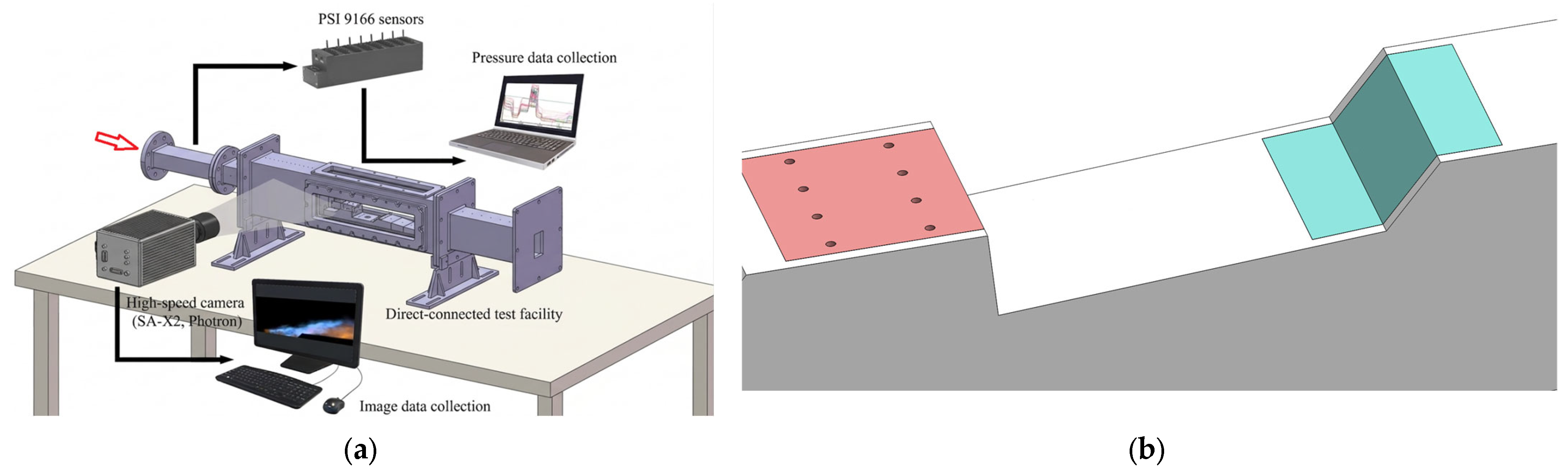
The overall experimental configuration is shown in Figure 1a. All the tests were conducted in a direct-connected supersonic combustion test facility. The test facility has been well-validated in previous supersonic combustion studies [8]. The test facility gives uniform, steady, and repeatable supersonic inflow. The combustor has a rectangular inlet with a cross-section of 50 mm × 30 mm, followed by a 250 mm long section with a half divergence angle of 3.43°. A rectangular cavity flameholder is installed on the lower wall at streamwise locations x = 250–340 mm (where x   =   0 defines the combustor inlet plane). The cavity has a length-to-depth ratio L u p p e r / D = 5 ( L u p p e r = 90   m m , D = 18   m m ) , with a right angle leading edge and a 45° beveled trailing edge. This cavity geometry is widely adopted in low-supersonic cavity combustor research because of the favorable flame stabilization characteristics [4].
The nominal inflow conditions are: Mach number Ma = 1.6, total temperature T 0 = 660   K , total pressure P 0 = 0.4 MPa, and inflow mass flow rate = 0.735 kg/s; flow uncertainty is less than 1%.
Figure 1b shows the two four-orifice fuel injection schemes, in which gaseous ethylene is injected through four circular orifices in two configurations: Far-Upstream Injection Scheme (FUI) and Near-Upstream Injection Scheme (NUI). The former is located 30 mm upstream of the CLE, and the latter is placed 10 mm upstream of the CLE. For both configurations, the center-to-center spacing between adjacent orifices is 10 mm, and the total orifice flow area is kept identical at 12.57 mm2 for both schemes under the actual inflow conditions of the diverging combustor [5]. The fuel injection pressure ratio reached 11.1, well above the critical value for ethylene, ensuring choked sonic jet exit conditions that further accelerated to supersonic speeds via expansion waves; an identical momentum flux ratio J = 2.2 was maintained for both schemes to isolate the axial location effect. The observed performance difference between the two schemes is the coupling result of the axial injection location and the streamwise evolution of inflow characteristics in the diverging channel.
Fuel is injected at a gauge pressure of 1 MPa and an ambient temperature of 300 K, with a fixed global equivalence ratio ϕ = 0.2 , which was a typical stable operating point for low-Mach cavity-stabilized supersonic combustion [12]. The key injection parameters are summarized in Table 1. The fuel mass flow rate was controlled with an uncertainty of less than 1%. We repeated all the tests at least three times to ensure repeatability, and the quantitative results presented are the average of three runs, with a relative standard deviation of less than 5% for all measured parameters.
For all the results presented, the inflection point of the cavity leading edge (CLE) is taken as the coordinate origin. The spatial coordinates are normalized by the cavity bottom length L bottom = 78.8 mm. The jet penetration depth is given in non-dimensional form as is common in relevant studies of supersonic jets and the cavity flow [9]. The overall measurement uncertainty of this work is less than 5%, covering inflow conditions, fuel injection, and optical diagnostics.

2.2. Measurement and Data Processing

Two synchronized optical diagnostic systems were used for flow-field and flame measurements: a Z-type high-speed schlieren and a side-view CH* chemiluminescence system. The high-speed schlieren used a 500 W xenon lamp, and it operated at 10,000 frames per second (fps) with an exposure time of 1/990,000 s. CH* chemiluminescence was used to record flame emission with a 430 ± 10 nm bandpass filter, which also operated at 10,000 fps with an exposure time of 1/10,000 s. Both were coupled to a Photron FASTCAM SA-X2 high-speed camera (1024 × 1024-pixel resolution; Photron Limited, Yonezawa, Japan).
Their synchronization accuracy is ±1 μs. Synchronized optical diagnostics of this kind are widely used to characterize supersonic flow and flame dynamics [13]. High-speed schlieren imaging can directly observe shear layers, shocks, and separation zones. Meanwhile, it can also be used to infer jet penetration and fuel mixing characteristics. CH* chemiluminescence provides a qualitative indication of heat release location and relative reaction intensity, but it does not represent a direct quantitative measure of absolute combustion intensity. In this study, CH* chemiluminescence intensity was treated as a relative value for comparing heat release distribution and unsteady fluctuation characteristics between the two schemes.
Jet penetration depth is extracted from time-averaged schlieren images using a multi-scale gray-level step detection algorithm. A Hough-transform-based shock mask suppresses spurious responses near strong shocks, which exclusively removes non-jet artifacts without altering the overall penetration depth boundary trend. This method has been verified through repeated implementation, yielding a total relative measurement uncertainty of jet penetration depth within 6%. Notably, this extraction approach is only valid for specified flow regions rather than the entire flow-field, which is further clarified in the subsequent result analysis [14,15].

3. Results and Discussion

3.1. Cold-Flow Characteristics

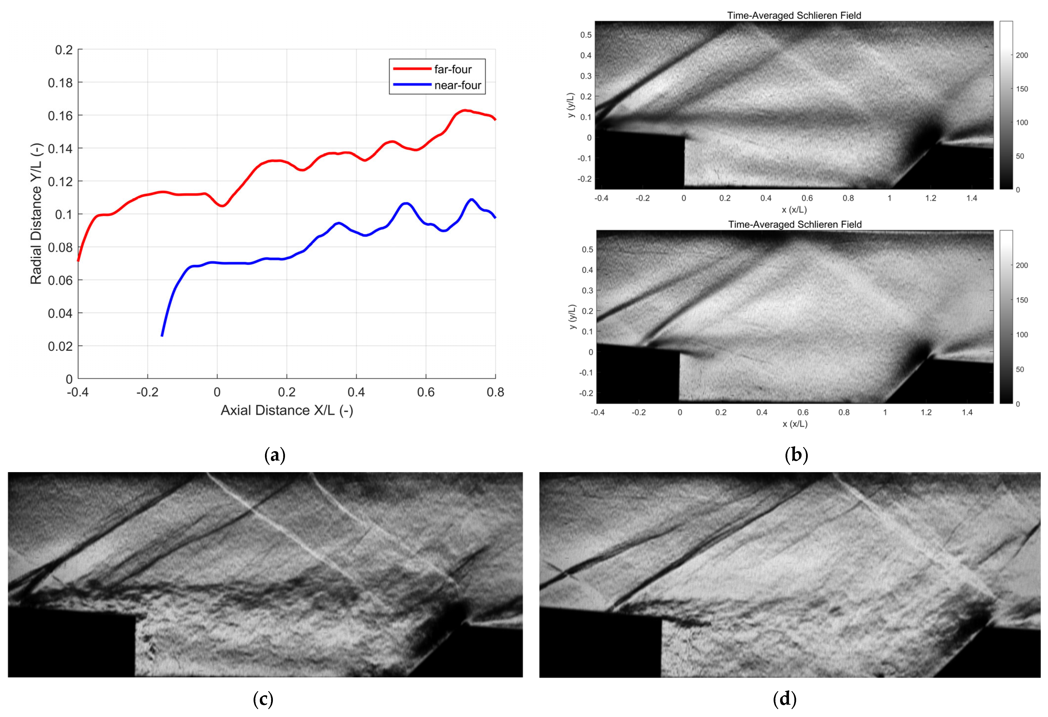
For both injection schemes, cold-flow experiments were performed at M a = 1.6 and T 0 = 660   K . We adopted non-dimensional fuel jet penetration profiles (Figure 2a) and time-averaged schlieren images (Figure 2b) to evaluate the effects of injection location on jet trajectory, shock wave structures, and cavity flow behavior. Jet penetration depth and shock evolution are indicators of the cold-flow mixing performance in the supersonic combustor [16].

3.1.1. Jet Penetration Depth Under Different Injection Schemes

Downstream jet-mainstream mixing gradually blurs the fuel boundary and reduces penetration measurement accuracy. Therefore, only a quasi-quantitative comparison was conducted in this section. As shown in Figure 2a, in the non-reacting Ma 1.6 flow, the non-dimensional penetration depth of the FUI ranged from 0.11 to 0.16, the streamwise-averaged value of which was 40–50% higher than that of the NUI, which ranged from 0.07 to 0.1, i.e., the FUI exhibited stronger penetration.
For both configurations, the penetration depth increased monotonically with the streamwise distance, but their evolutionary trends differed significantly. The FUI jet penetrated rapidly in the upstream region and then gradually saturated, while the NUI jet exhibited an irregular streamwise penetration profile due to the rapid mixing and dissipation in the supersonic mainstream.

3.1.2. Flow Structure Evolution in Cold Flow

As shown in Figure 2b–d, the three dominant flow features are clearly observed via schlieren: the merged bow shock induced by four-orifice jets, the interaction between jet-induced shocks and the incoming boundary layer, and the density gradient structure of the cavity shear layer. The interaction between these features significantly affects the flow uniformity and stability inside the cavity combustor [11].
The bow shocks induced by the four-orifice jets of the FUI scheme formed a continuous merged planar shock due to the superposition of shocks from adjacent orifices, with a wider upstream influence range and more significant flow blockage. The merged bow shock interacted with the incoming boundary layer and created an obvious density gradient zone near the cavity leading edge.
For the NUI scheme, the injector was placed only 10 mm upstream of the CLE. Such a close layout induced intense interaction between the fuel jet and the cavity leading-edge shear layer, accelerating jet mixing and momentum dissipation. Accordingly, the high-fluctuation zone near the injector connected seamlessly with that at the CLE.

3.2. Combustion Flow Characteristics

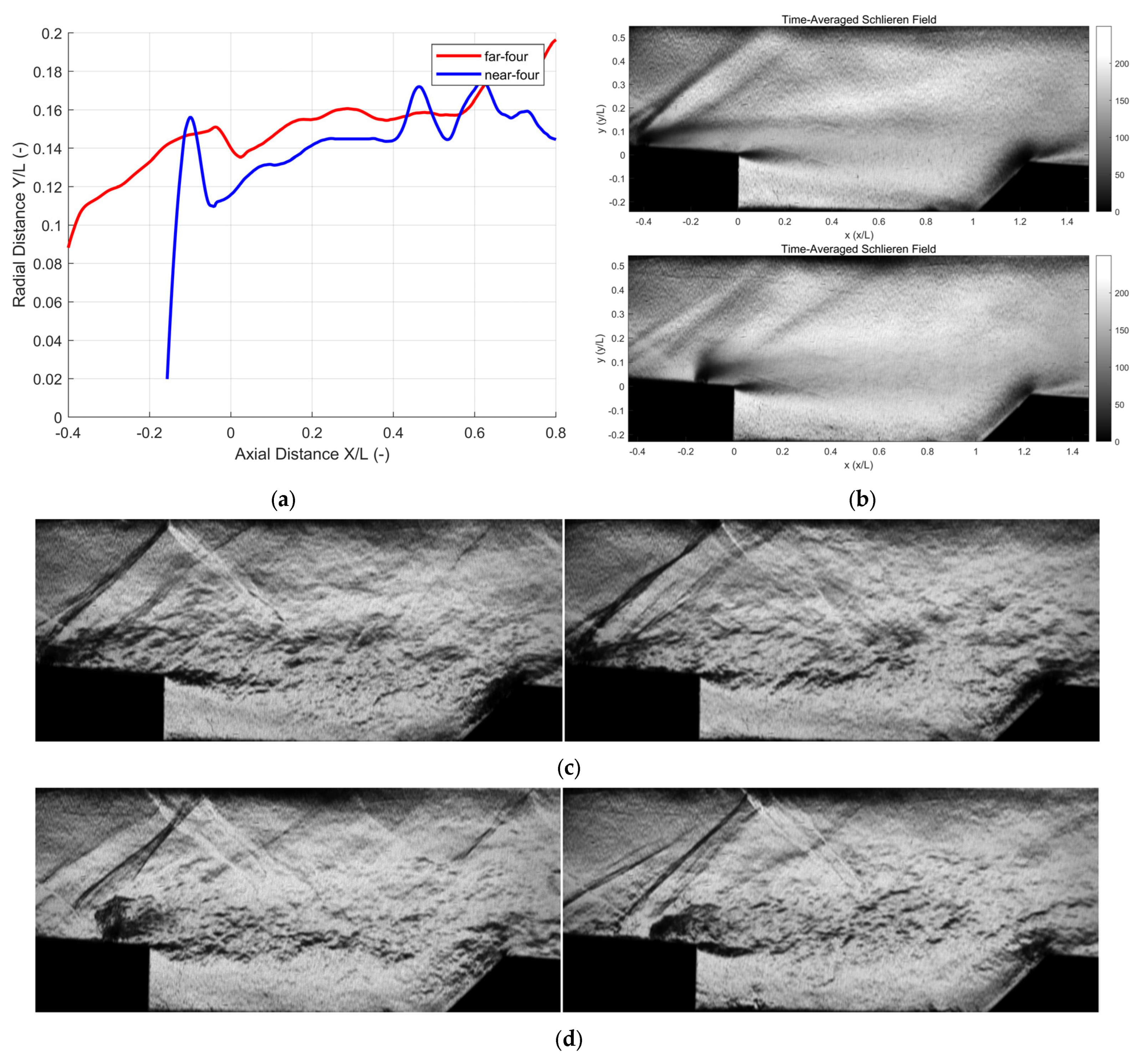
Reacting-flow characteristics were also investigated at M a = 1.6 , T 0 = 660 K, and ϕ = 0.2 . Figure 3a shows the non-dimensional jet penetration depth and heat release boundary under reacting conditions, and Figure 3b shows the corresponding time-averaged schlieren. We can identify the modulation effect of combustion heat release on jet–cavity flow interactions by comparing with the cold-flow results; this is a common method in supersonic combustion research.

3.2.1. Jet Penetration and Thermal Expansion Effects

As shown in Figure 3a, in front of the cavity (x/L < 0), heat release significantly improved penetration. In the NUI scheme, the curve showed local peaks corresponding to the non-uniform penetration of individual orifices, which then merged to the average level due to rapid mixing. After entering the cavity section (x/L > 0), combustion occurred in the jet wake, making it hard to extract jet penetration information from the schlieren image.
Combustion heat release enhanced jet penetration for both schemes and significantly narrowed the penetration gap formed under cold-flow conditions. This phenomenon was consistent with the forward movement of the combustion-induced average shock presented in Figure 3b, and the penetration enhancement effect was far more remarkable for the NUI scheme. In the front half of the cavity (x/L < 0.2) under reacting conditions, the relative difference in non-dimensional penetration depth between the NUI and FUI schemes was less than 9%. This demonstrated that the NUI scheme could greatly enhance jet penetration and offset the penetration difference compared with the FUI scheme under cold-flow conditions [12].
The fundamental mechanism underlying combustion-induced jet penetration enhancement is that heat-release-induced differential boundary layer separation modulates the jet-to-crossflow momentum flux ratio, which is a key determinant of jet penetration depth.
For the NUI scheme, intense jet–cavity interaction concentrates heat release in the forepart of the cavity. This localized high heat release significantly intensifies upstream boundary layer separation and reduces the near-wall crossflow velocity. A simple 1D estimate of Mach number reduction due to heat release, based on standard Rayleigh flow theory, suggests that this concentrated heating may reduce the local Mach number by approximately 15–20% (from 1.6 to ~1.3–1.35) in the injection region, further lowering the crossflow momentum flux. As a result, the momentum flux of the incoming crossflow at the jet exit plane decreases substantially, leading to a marked increase in the jet-to-crossflow momentum flux ratio. This elevated momentum ratio deflects streamlines upward, ultimately resulting in a significant increase in jet penetration depth.
In contrast, the weaker jet–cavity interaction under the FUI scheme confines heat release to the rear cavity region. This leads to a much smaller estimated Mach number reduction of ~3–7% in the FUI injection region. Although combustion does induce boundary layer separation upstream of the cavity, the intensity of separation is lower, and its influence range is relatively smaller, leading to only minor changes in the jet penetration characteristics.

3.2.2. Flow Structure Evolution in Reacting Flow

As shown in Figure 3c,d, under combustion conditions, the merged bow shock of the FUI scheme gradually weakened with a blurred shock front and a narrowed upstream influence scope. Consistent with the inherent flow characteristics of this injection layout, its dual fluctuation zone layout remained stable, while the intensity of each flow structure declined and further expanded the distribution range of the shock-induced density gradient.
In contrast, for the NUI scheme, the significantly increased jet penetration depth led to a larger upstream separation zone, with the separation shock shifting further upstream. A strong jet shock remained visible in the main flow. This merging was accompanied by intense jet oscillations and a distinct upward deflection of the jet column, resulting in a more complex shock system and a wider oscillation range [12].
At the injection position, the schlieren morphology of the FUI scheme remained relatively stable with slight fluctuations. In comparison, the NUI scheme exhibited much more obvious variations, leading to altered injection uniformity, which was consistent with the subsequent experimental observations.

3.3. Flame Structure and Combustion Stability

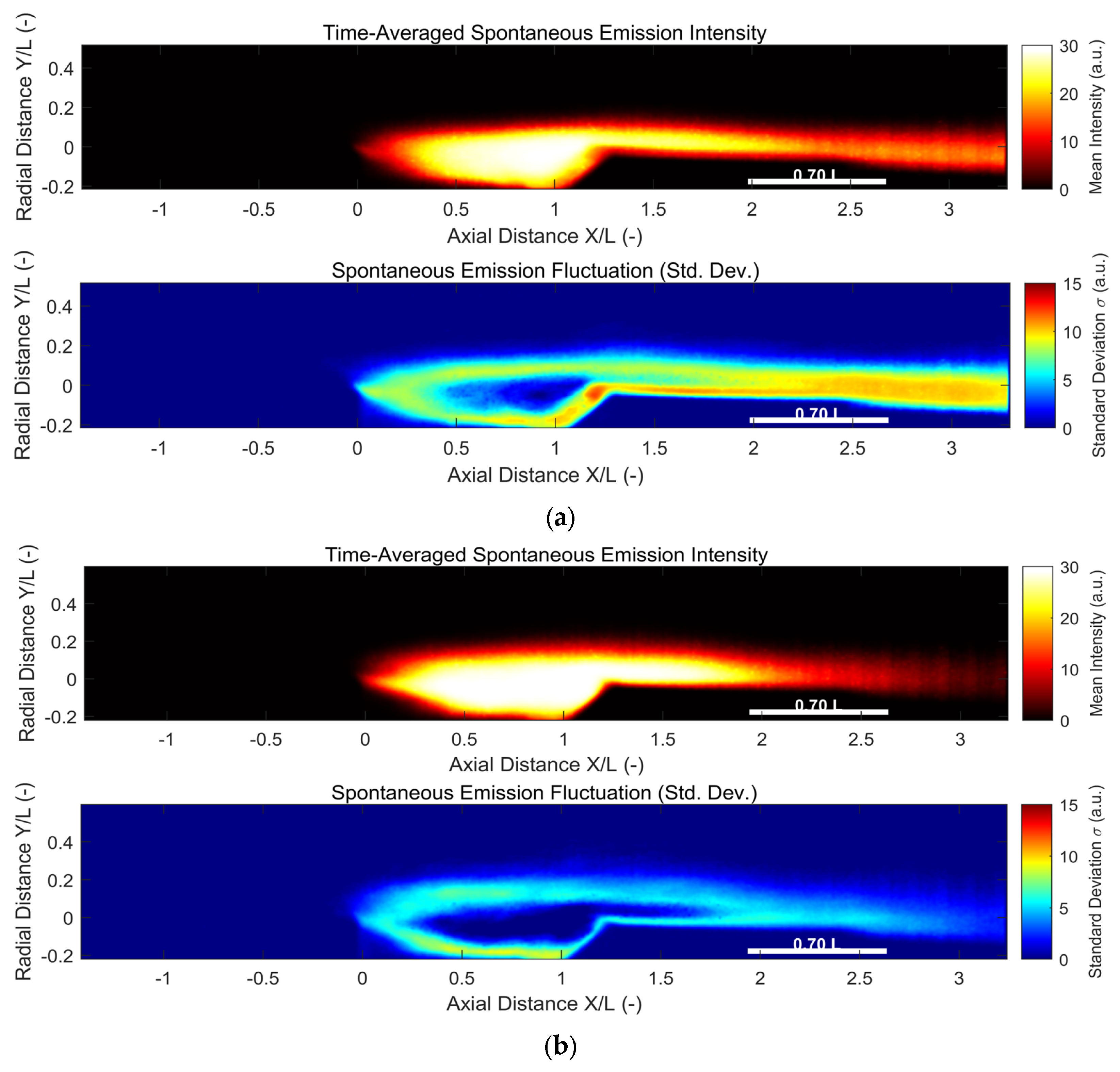
Figure 4 shows the results of flame dynamics investigations via time-averaged and instantaneous CH* chemiluminescence imaging. CH* chemiluminescence is a widely accepted qualitative marker for the location and range of the main heat release zone in supersonic hydrocarbon combustion [13]. The upper row presents the time-averaged CH* relative intensity, and the lower row shows the root-mean-square (RMS) of CH* signals to characterize the unsteady fluctuation characteristics of the flame. All fields are normalized to a unified color scale for direct comparison.

3.3.1. Time-Averaged Flame and Heat Release Distribution

Figure 4a,b show the intensity distribution of CH* chemiluminescence for the two schemes. The two injection schemes produced distinctly different flame patterns, with flame distribution observed downstream of the cavity for both configurations, which was consistent with the flow-field evolution analyzed above.
For the FUI scheme, the flame front shifted downstream, with the main reaction zone concentrated in the rear half of the cavity and the near-downstream region.
No stable high-intensity reaction zone was formed in the front section of the cavity. For the NUI scheme, the initial flame zone was highly coincident with the CLE separation zone, with ignition occurring much closer to the CLE.
The main reaction zone extended across the entire cavity with a relatively uniform distribution, and the downstream flame was more concentrated with higher mean intensity [17].

3.3.2. Flame Stability and Quantitative Comparison

Instantaneous schlieren snapshots (Figure 3c,d) reveal dramatically different dynamic behaviors. For the FUI scheme, more regular and visually stable flow structures were observed, with a well-defined continuous bow shock and an intact jet column. In contrast, the NUI scheme showed obvious jet lifting, fragmentation, and rapid morphological changes between consecutive snapshots, indicating intense jet–cavity interaction.
The RMS of CH* chemiluminescence relative intensity is used to characterize the unsteady fluctuation of flame heat release and evaluate combustion stability. The low CH* chemiluminescence standard deviation in the region ( x / L   =   0.1 0 ) indicated stable combustion.
Taking the standard deviation σ of CH* chemiluminescence as the quasi-quantitative index, the FUI scheme exhibited widespread high-amplitude fluctuations ( σ > 8   a . u . ) in the near-wall region of the rear cavity at x / L = 0.7 1.3 , with an averaged σ of approximately 10 a.u. Consequently, the low-σ region (σ < 3 a.u.), indicating stable heat release, was confined to the central recirculation zone at x / L = 0.7 1.2 , beyond which combustion lost stability under strong fluctuations. This phenomenon corresponded well to the high activity of fluctuating jet trails observed in the schlieren results in Figure 5.
In contrast, the NUI scheme confined severe fluctuations to the bottom-wall ignition zone, with the averaged σ in the rear cavity dropping to around 3.4 a.u., which was 63% lower than that of the FUI scheme. Its stable flame core extended continuously from x / L 0.2 to 1.8 and maintained favorable stability owing to the strong jet–cavity coupling effect. For the FUI scheme, however, the weak jet–cavity interaction led to a more oscillating jet wake flame [13].
From the perspective of flame stabilization mode, the low-value region of core heat release reflected by CH* standard deviation contours indicated that stable combustion could be maintained across the whole cavity under the NUI scheme, which was mainly realized through shear layer flame stabilization. In contrast, the FUI scheme only formed a narrow stable region near the cavity rear portion, with its flame stabilization predominantly dominated by the cavity recirculation zone.

3.3.3. Flow–Flame Frequency Correlation

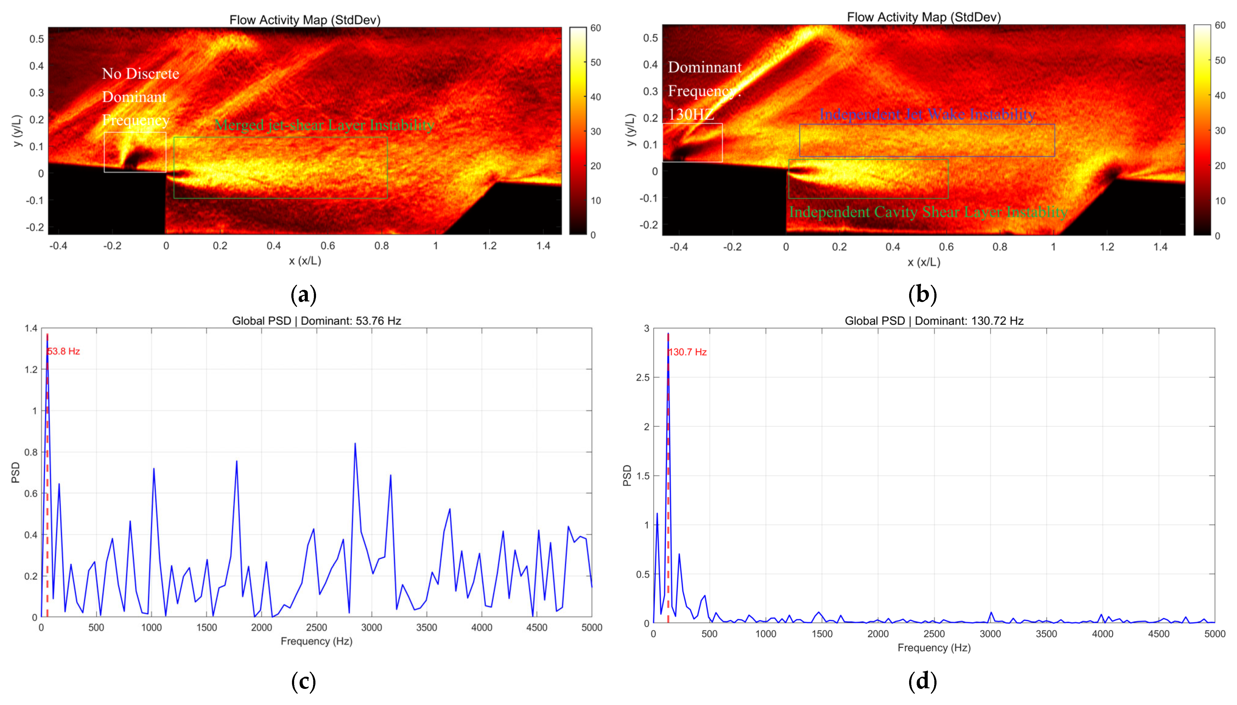
To clarify the intrinsic correlation between flow unsteadiness and flame fluctuation, we compared the RMS fluctuation fields derived from synchronized high-speed schlieren images with those obtained from CH* chemiluminescence measurements. The schlieren RMS distributions are shown in Figure 5a,b, and the corresponding power spectral density (PSD) frequency analysis results at the injector orifice are presented in Figure 5c,d.
For the NUI scheme (Figure 5a), the flow-field presented a single continuous main high-fluctuation region, whose spatial range was highly matched with the flame high-fluctuation region observed in the CH* results. This high-fluctuation region covered the jet wake zone and cavity leading-edge shear layer zone, representing the coupled flow instability distribution with no spatially separated fluctuation regions. A weak discrete peak at 53.8 Hz was observed in the PSD at the injector orifice, with a signal-to-noise ratio close to the 3× threshold. This low-frequency oscillation became the dominant global flow feature in the spatially averaged PSD of the entire flow-field, with an SNR of approximately 7.7. However, the flow fluctuation energy remained predominantly dispersed in a wide frequency range, and the overall flow-field was still dominated by broadband turbulent fluctuations.
For the FUI scheme (Figure 5b), two spatially separated high-fluctuation regions were observed in the flow-field. The upper instability region was located in the jet wake zone, while the lower instability region at the CLE was located in the cavity shear layer zone. A high-energy discrete dominant frequency of 130.7 ± 2 Hz was captured locally at the injector orifice, corresponding to a Strouhal number of 0.018 based on the cavity upper opening length L = 90 mm and freestream velocity U = 670 m/s. This local frequency is 8% lower than the pure rectangular cavity first-mode natural frequency (142 Hz, modified Rossiter formula), which may be attributed to the aft ramp geometry, upstream wall divergence, and combustion-induced flow perturbations. The observed fluctuation is therefore likely a complex coupled mode. Jet instabilities already present in the cold-flow state may act as a potential trigger for flame fluctuations. These instabilities could modulate local fuel-air mixing and subsequent heat release, while the jet–cavity coupled mode may contribute to the observed dominant frequency modulation. This suggests a possible causal link between the flow and flame dynamics. This frequency component showed good spatial correlation with the high-amplitude flame fluctuation zone identified from CH* RMS contours. It should be noted that this local frequency is spatially correlated with combustion unsteadiness rather than confirmed as a direct causal driver of instability.
Flow fluctuation frequency characteristics are closely correlated with combustion stability under the test conditions: broadband fluctuation without a high-energy discrete dominant frequency corresponds to lower global flame fluctuation, while high-energy discrete oscillation leads to intense flame unsteadiness [11]. Transient schlieren observations provided direct visual evidence for the two distinct flow fluctuation modes identified by RMS and FFT analysis. It is important to distinguish between local and global flow instabilities. The 130.7 Hz dominant frequency in the FUI scheme was a strong local jet instability that was clearly observed both at the injector orifice and in the global flow-field, with an SNR exceeding 12. In contrast, the 53.8 Hz oscillation in the NUI scheme was a weak global cavity mode that was barely detectable at the injector location, and its energy was more than 40% lower than that of the FUI dominant frequency. This difference in instability characteristics directly explained the superior combustion stability of the NUI scheme.
The comparison of the characteristics of the two schemes in this study is shown in Table 2.

4. Conclusions

A systematic investigation on both the cold-flow mixing and combustion characteristics of FUI and NUI four-orifice injection schemes in a M a   =   1.6 cavity combustor at T 0   =   660   K and ϕ   =   0.2 was implemented using synchronized high-speed schlieren and CH* chemiluminescence diagnostics:
  • Jet penetration and flow-field: The axial location of upstream fuel injection significantly alters the coupling between jet penetration and heat release. While FUI produced greater penetration under cold-flow conditions, the NUI scheme’s closer proximity to the cavity leading edge enabled stronger jet–cavity interaction, which amplified combustion-induced penetration enhancement and effectively equalized the penetration performance between the two schemes.
  • Frequency-domain characteristics: The spatial distribution of fluctuation regions and their frequency characteristics were fundamentally different between the two schemes. FUI maintained dual separated fluctuation zones and a discrete dominant frequency, while NUI produced a single continuous high-fluctuation region with broadband spectral characteristics, indicating fundamentally different instability generation mechanisms.
  • Combustion and Stability: Flame stabilization modes differed critically: FUI relied predominantly on cavity recirculation-zone stabilization in the rear portion, while NUI utilized shear-layer flame holding across the entire cavity length. This difference in stabilization mechanism directly determined the combustion stability characteristics, with NUI demonstrating superior performance in maintaining stable heat release distribution.
This work has several limitations: CFD simulations were not performed, experiments were limited to a single equivalence ratio and Mach number, and the optical diagnostics provide line-of-sight averaged information. Future studies will address these limitations by covering broader operating conditions, employing planar diagnostics, and incorporating numerical simulations to further reveal heat release regulation mechanisms.

Author Contributions

Conceptualization, L.L. and J.L.; investigation, L.L.; writing—original draft, L.L.; writing—review and editing, J.L.; supervision, J.L. All authors have read and agreed to the published version of the manuscript.

Funding

This research received no external funding.

Institutional Review Board Statement

Not applicable.

Informed Consent Statement

Not applicable.

Data Availability Statement

The original contributions presented in this study are included in the article. Further inquiries can be directed to the corresponding author.

Acknowledgments

Doubao 2.0 (https://www.doubao.com/) was used to check for textual errors and inappropriate expressions in the manuscript, and Grammarly (https://coda.grammarly.com/) was used for language proofreading.

Conflicts of Interest

The authors declare no conflicts of interest.

Abbreviations

The following abbreviations are used in this manuscript:
CLECavity Leading Edge
FUIFar-Upstream Injection (30 mm upstream of CLE)
NUINear-Upstream Injection (10 mm upstream of CLE)
RMSRoot Mean Square
FFTFast Fourier Transform

References

  1. Micka, D.J.; Driscoll, J.F. Combustion Characteristics of a Dual-Mode Scramjet Combustor with Cavity Flameholder. Proc. Combust. Inst. 2009, 32, 2397–2404. [Google Scholar] [CrossRef]
  2. Rajesh, A.C.; Jeyakumar, S.; Jayaraman, K.; Karaca, M. Steady and Unsteady Flow Characteristics of Dual Cavity in Strut Injection Scramjet Combustor. Int. J. Hydrogen Energy 2023, 48, 28174–28186. [Google Scholar] [CrossRef]
  3. Ben-Yakar, A.; Hanson, R.K. Cavity Flame-Holders for Ignition and Flame Stabilization in Scramjets: An Overview. J. Propuls. Power 2001, 17, 869–877. [Google Scholar] [CrossRef] [PubMed]
  4. Allen, W.; King, P.; Gruber, M.; Carter, C.; Hsu, K.-Y. Fuel-Air Injection Effects on Combustion in Cavity-Based Flameholders in a Supersonic Flow. In Proceedings of the 41st AIAA/ASME/SAE/ASEE Joint Propulsion Conference & Exhibit, Tucson, AZ, USA, 10–13 July 2005. [Google Scholar] [CrossRef]
  5. Peng, S.-S.; Zhou, W.-X.; Qi, Y.-Y.; Shi, H.-H.; Li, R.-W.; Zhu, L. Effect of Kerosene Dual-Jet Spacing on the Mixing and Combustion Characteristics of a Scramjet Combustor. ACS Omega 2024, 9, 33482–33493. [Google Scholar] [CrossRef] [PubMed]
  6. Ben Ali, N.; Basem, A.; Ghodratallah, P.; Singh, P.K.; Jasim, D.J.; Sultan, A.J.; Eladeb, A.; Kolsi, L.; El-Shafay, A.S. The Usage of Non-Aligned Multi-Circular Winding Injectors for Efficient Fuel Mixing inside the Scramjet Engine. Energy 2024, 298, 131403. [Google Scholar] [CrossRef]
  7. Zhang, P.; Li, Z.; Abdollahi, S.A. Computational Modeling of the Rectangular Non-Aligned Multi-Injector for Efficient Fuel Mixing in a Supersonic Combustion Chamber. Sci. Rep. 2024, 14, 15959. [Google Scholar] [CrossRef] [PubMed]
  8. Ji, J.; Cai, Z.; Wang, T.; Wang, Z.; Sun, M. Experimental Study on Combustion Modes and Oscillations in a Cavity-Based Scramjet Combustor. AIAA J. 2024, 62, 915–927. [Google Scholar] [CrossRef]
  9. Li, L.; Huang, W.; Yan, L.; Du, Z.; Fang, M. Numerical Investigation and Optimization on the Micro-Ramp Vortex Generator within Scramjet Combustors with the Transverse Hydrogen Jet. Aerosp. Sci. Technol. 2019, 84, 570–584. [Google Scholar] [CrossRef]
  10. Gruber, M.R.; Donbar, J.M.; Carter, C.D.; Hsu, K.-Y. Mixing and Combustion Studies Using Cavity-Based Flameholders in a Supersonic Flow. J. Propuls. Power 2004, 20, 769–778. [Google Scholar] [CrossRef]
  11. Cao, D.; Brod, H.E.; Yokev, N.; Michaels, D. Flame Stabilization and Local Combustion Modes in a Cavity-Based Scramjet Using Different Fuel Injection Schemes. Combust. Flame 2021, 233, 111562. [Google Scholar] [CrossRef]
  12. Mathur, T.; Gruber, M.; Jackson, K.; Donbar, J.; Donaldson, W.; Jackson, T.; Billig, F. Supersonic Combustion Experiments with a Cavity-Based Fuel Injector. J. Propuls. Power 2001, 17, 1305–1312. [Google Scholar] [CrossRef] [PubMed]
  13. Yuan, Y.; Zhang, T.; Yao, W.; Fan, X. Study on Flame Stabilization in a Dual-Mode Combustor Using Optical Measurements. J. Propuls. Power 2015, 31, 1524–1531. [Google Scholar] [CrossRef]
  14. Guardone, A.; Zocca, M.; Gajoni, P.; Mondonico, F.; Conti, C.C. Characteristics-Based Measurements of Supersonic Flows from Schlieren Images. Exp. Fluids 2025, 66, 72. [Google Scholar] [CrossRef]
  15. Luthman, E.; Cymbalist, N.; Lang, D.; Candler, G.; Dimotakis, P. Simulating Schlieren and Shadowgraph Images from LES Data. Exp. Fluids 2019, 60, 134. [Google Scholar] [CrossRef]
  16. Relangi, N.; Ingenito, A.; Jeyakumar, S. The Implication of Injection Locations in an Axisymmetric Cavity-Based Scramjet Combustor. Energies 2021, 14, 2626. [Google Scholar] [CrossRef]
  17. Dhankarghare, A.A.; Jayachandran, T.; Muruganandam, T.M. Comparative Investigation of Strut Cavity and Wall Cavity in Supersonic Flows. Aerosp. Sci. Technol. 2022, 124, 107520. [Google Scholar] [CrossRef]
Figure 1. Schematic of the experimental setup. (a) Overall layout of the supersonic combustion test system; (b) schematic of the four-orifice injection scheme upstream of the CLE.
Applsci 16 05913 g001
Figure 2. Fuel penetration characteristics and schlieren flow-field structure in non-reacting supersonic flow: (a) fuel penetration depth distribution, normalized by L b o t t o m = 78.8   m m ; (b) time-averaged schlieren visualization; (c) representative transient schlieren snapshot of the cold flow-field for the FUI scheme; (d) representative transient schlieren snapshot of the cold flow-field for the NUI scheme.
Applsci 16 05913 g002
Figure 3. Local fuel penetration, local heat release boundary characteristics and schlieren flow-field structure in reacting supersonic flow: (a) distribution of fuel penetration depth and heat release boundary under combustion conditions, normalized by L b o t t o m = 78.8   m m ; (b) the time-averaged schlieren visualization of the reacting flow-field; (c) two representative transient schlieren snapshots of the reacting flow-field for the FUI scheme; (d) two representative transient schlieren snapshots of the reacting flow-field for the NUI scheme.
Applsci 16 05913 g003
Figure 4. Combustion characteristics from CH* chemiluminescence and instantaneous cold and reacting-flow structures from schlieren imaging for cavity flames under different four-orifice injection schemes (feature size 0.7 L): (a) FUI configuration: time-averaged intensity and standard deviation of CH* spontaneous emission; (b) NUI configuration: time-averaged mean intensity and standard deviation of spontaneous emission.
Applsci 16 05913 g004
Figure 5. Annotated schlieren RMS fields and corresponding power spectral density (PSD) analysis under combustion conditions: (a) NUI scheme: the flow-field presents a single merged high-fluctuation region, with no high-energy discrete dominant frequency detected; (b) FUI scheme: fluctuation field and corresponding PSD at the injector orifice; (c) PSD of schlieren intensity fluctuations at the injector orifice for the NUI scheme; (d) PSD of schlieren intensity fluctuations at the injector orifice for the FUI scheme.
Applsci 16 05913 g005
Table 1. Key parameters of the fuel injection schemes.
Injection SchemeDistance Upstream of CLE (mm)Injection AngleJet Orifice Diameter (mm)Momentum Flux Ratio J
FUI3090°2 2.2
NUI1090°2 2.2
Table 2. Characteristic comparison between FUI and NUI injection schemes.
Comparison ItemFUI SchemeNUI Scheme
Jet Penetration40–50% higher average penetration under cold flow; advantage significantly weakened under combustion with increased spatial fluctuationLower cold-flow penetration; remarkably enhanced under combustion, with penetration difference <9% in the fore-cavity ( x / L < 0.2 )
Flow-Field and FluctuationTwo separated high-fluctuation regions; high-energy discrete dominant frequency at 130.7 HzSingle continuous high-fluctuation region; broadband fluctuation without discrete dominant frequency
Flame and Heat ReleaseIgnition delayed to mid-rear cavity; main reaction zone concentrated in the rear half of the cavityIgnition anchored near cavity leading-edge separation zone; flame uniformly distributed over the entire cavity
Combustion StabilityAverage CH* RMS ≈ 10 a.u. in the rear cavity; narrow stable flame core with poor downstream sustainabilityAverage CH* RMS ≈ 3.4 a.u. (63% lower) in the rear cavity; stable flame core extending to x/L ≈ 1.8
Disclaimer/Publisher’s Note: The statements, opinions and data contained in all publications are solely those of the individual author(s) and contributor(s) and not of MDPI and/or the editor(s). MDPI and/or the editor(s) disclaim responsibility for any injury to people or property resulting from any ideas, methods, instructions or products referred to in the content.