1. Introduction
International shipping contributes about 2–3% of global anthropogenic greenhouse-gas emissions and is subject to tightening decarbonisation policies such as the revised IMO GHG strategy and regional measures [
1,
2]. Domestic and short-sea shipping, including coastal cargo services, has become a priority segment because routes are short, close to populated areas, and well suited to electrification and hybridisation [
3,
4]. Coastal cargo vessels operate frequent port-to-port services with highly variable loads and long periods at part load, where conventional mechanical propulsion is inefficient, leading to unnecessary fuel use and emissions [
5,
6]. Hybrid electric propulsion systems (HEPSs) combine engines, batteries, electric machines, and power electronics under an energy management strategy and can significantly reduce fuel consumption and emissions when properly sized and controlled [
5].
Li-ion battery energy storage systems are central to marine HEPS because of their favourable energy and power density, yet they remain cost-intensive and subject to degradation that depends on operating profiles, cycling depth, and temperature [
7]. Against this backdrop, the present paper develops a model-based, data-driven framework for the integrated design and dynamic performance optimisation of a diesel-battery HEPS for a representative coastal cargo vessel operating on short-sea routes. The contributions of this study can be summarised as follows, together with the specific gaps they address:
(1) Vessel and trade focus: The framework is applied to a representative coastal general cargo vessel on short-sea routes, rather than the more commonly studied tugs, ferries or offshore support vessels. This addresses the limited attention given to coastal cargo trades in existing HEPS studies, despite their significant share of domestic and regional shipping.
(2) Route-specific, multi-year operational profiles: Time-resolved, route-specific operating profiles are reconstructed from multi-year AIS records and logbook data, instead of relying on stylised duty cycles or a few representative operating points. This closes the gap where previous sizing–control studies often neglect the variability and heterogeneity of real coastal operations.
(3) Degradation-aware battery economics in LCC: A lithium-ion battery degradation model is embedded directly in the life-cycle cost formulation, explicitly capturing replacement timing and residual value. This addresses the common simplification where batteries are treated as ideal storage devices or represented by coarse lifetime factors without consistent economic integration.
(4) Surrogate-assisted bi-level optimisation under realistic constraints: The integrated design problem is formulated as a bi-level optimisation in which a surrogate-assisted upper level searches over engine and ESS sizes, while a dynamic-programming-based lower level computes optimal energy management policies under realistic SOC, C-rate and power constraints. This responds to gaps in earlier work where component sizing and control are optimised separately or only evaluated under simplified, computationally convenient scenarios.
The remainder of this paper is organised as follows.
Section 2 reviews decarbonisation drivers, hybrid electric architectures, energy management strategies, battery degradation and data-driven operational profiling for marine HEPSs.
Section 3 presents the modelling of the coastal cargo vessel, the hybrid electric propulsion system and the life-cycle cost formulation.
Section 4 introduces the surrogate-assisted bi-level optimisation framework.
Section 5 describes the case-study vessel, routes, data processing and numerical setup.
Section 6 reports and discusses the main results, including comparisons with baseline configurations and sensitivity analyses. Finally,
Section 7 concludes the paper and outlines implications and avenues for future work on coastal cargo hybridisation.
2. Literature Review
2.1. Decarbonisation Drivers for Coastal and Short-Sea Shipping
International and regional policy frameworks have made domestic and short-sea shipping a focal point for early deployment of low- and zero-emission technologies. The IMO Initial GHG Strategy sets sector-wide reduction targets and has triggered a large body of scenario and policy analysis on pathways to meet these goals [
1,
2,
8]. Recent work by the International Transport Forum specifically highlights coastal and feeder trades as promising candidates for electrification and alternative fuels because of their relatively short routes and predictable schedules [
4,
9]. Case studies on port electrification and shore-power readiness further underline the role of regional policy and infrastructure in enabling hybrid and fully electric vessels in coastal corridors [
3,
10]. These studies collectively motivate a detailed examination of hybrid electric propulsion options for coastal cargo vessels, which remain less explored than passenger ferries or offshore support vessels.
2.2. Hybrid Electric Propulsion Architectures and Case Studies
Hybrid electric propulsion systems (HEPSs) integrate diesel or dual-fuel engines, electric machines, power electronics, and energy storage to improve overall efficiency and flexibility. An early comprehensive review by Geertsma et al. [
5] summarised hybrid architectures, control concepts, and expected benefits for smart ships. More recent surveys emphasise the rapid expansion of hybrid concepts across vessel types and discuss design trade-offs between DC and AC distribution, redundancy, and safety [
11,
12,
13]. Case studies on hybrid ferries, workboats, and support vessels consistently report fuel savings of 10–30% and improved transient performance, but also reveal strong sensitivity to operational profiles and component sizing choices [
14,
15,
16].
Several studies have analysed hybrid or fuel-cell-based propulsion for smaller passenger and coastal vessels. For instance, Rafiei et al. [
17] evaluated a fuel-cell/battery hybrid ferry and highlighted the importance of powersharing strategies for system longevity, while Kortsari et al. [
18] quantified the economic performance of a pure-electric ferry relative to a diesel baseline, showing that capital expenditure and charging strategy largely determine competitiveness. Life-cycle analyses suggest that battery-electric or hybrid ships can reduce well-to-wake emissions, but that benefits depend on grid carbon intensity and realistic load profiles [
19]. However, most of these case studies focus on ferries or small passenger vessels; coastal general cargo ships serving multi-port routes receive comparatively little attention.
2.3. Energy Management Strategies for Marine HEPSs
Energy management strategies (EMSs) are central to realising the potential of HEPSs. Rule-based controllers remain common in practice due to their transparency and ease of certification, but they often underutilise the degrees of freedom provided by hybrid architectures [
11,
14]. Optimisation-based EMS formulations including dynamic programming (DP), equivalent consumption minimisation strategies (ECMSs), and model predictive control (MPC) have been widely investigated for marine applications, often using reference mission profiles or synthetic load cycles [
13,
15,
16]. These works demonstrate non-trivial fuel savings and better engine loading but are typically applied to a single or small set of operational scenarios.
More recent contributions increasingly explore advanced or data-driven EMS. Multi-objective and population-based optimisation methods have been used to coordinate batteries and fuel cells in hybrid ships, trading off fuel use, emissions, and component stress [
20,
21]. Reinforcement learning and other AI-based approaches have been proposed for hydrogen and battery hybrid vessels, with promising results under simulated conditions [
22]. Hierarchical and hybrid MPC structures are being developed to manage multi-source power systems in the presence of constraints and forecast information [
23,
24]. Although these studies show that sophisticated EMSs can extract more benefit from hybridisation, they typically assume fixed component sizes and do not close the loop with long-term life-cycle economics. At the lower-level control layer of this framework, we chose DP over ECMS or MPC because DP can overcome nonlinear constraints and provide a global optimum solution, which is crucial for accurately evaluating the extreme performance of different engine/battery capacity combinations during the design phase. Although the computational complexity of DP limits its online application, as an offline design tool, it eliminates the interference of sub-optimality in control strategies on hardware selection results, providing the most objective basis for upper-level configuration.
2.4. Battery Degradation and Life-Cycle Economics
Li-ion batteries are central to most marine HEPSs, but their cost and finite life add complexity to the design problem. A substantial body of work addresses Li-ion performance degradation modelling for transport and marine applications, ranging from physics-based models to semi-empirical formulations suited for system-level studies [
25,
26]. Chen et al. [
27] proposed a semi-empirical performance degradation model for LiFePO
4 batteries and integrated it into the life-cycle cost (LCC) optimisation of an electrified ferry, showing that degradation-aware sizing can significantly reduce total LCC compared to fuel-economy-only designs. Prognostics and health management (PHM) concepts have been introduced to optimise maintenance schedules and extend life for marine hybrid energy systems, emphasising the interplay between EMS, thermal management, and degradation [
28].
While several marine HEPS studies now acknowledge battery ageing, they often treat degradation via simplified lifetime factors or assume fixed replacement intervals [
14,
16]. More detailed degradation-aware designs remain relatively rare, especially for coastal cargo vessels with heterogeneous and route-dependent operating patterns. Economic assessments for electric and hybrid ferries also indicate that battery replacement cost, salvage value, and evolving battery prices critically shape competitiveness over a 20-year horizon [
18,
19]. This motivates the explicit integration of degradation models and replacement timing into hybrid propulsion LCC formulations.
2.5. Data-Driven Operational Profiles and Integrated Design Frameworks
Accurate representation of ship operating profiles is essential for meaningful HEPS design and evaluation. Recent years have seen increased use of automatic identification system (AIS) data, weather information, and onboard monitoring to reconstruct speed, power, and operational-mode profiles for individual vessels and routes. Data-driven EMS development using AIS and environmental data has been proposed to smooth fuel-cell operation and reduce transient stress in hybrid power systems [
29]. Operational profiles derived from AIS and EU MRV data have also been used to benchmark energy-efficiency measures and identify route-specific decarbonisation options for coastal and short-sea shipping [
30].
Despite this progress, many HEPS sizing and EMS studies still rely on stylised “typical” duty cycles, short synthetic missions, or a limited number of design points [
5,
11]. Stochastic operational models and Markov chain-based profile generation have recently been proposed to better capture operational variability for hybrid ships [
31]. However, there remains a shortage of frameworks that directly embed multi-year, route-specific profiles into integrated design-and-control optimisation, particularly for coastal cargo vessels operating across multiple ports and operating regimes.
Based on the above literature, while research on hybrid propulsion systems for ferries and harbour tugs has reached a relatively mature stage, existing studies still exhibit a significant gap in the deep coupling of “ship-data-driven” approaches and “degradation-aware optimization” when addressing the variable route dynamics and long-term life-cycle cost balance of coastal general cargo ships. Therefore, the integrated framework proposed in this study is not a simple superposition of functions, but rather aims to address this disconnect between system modelling and actual operational conditions.
2.6. Gaps and Positioning of the Present Work
The literature indicates that (i) hybrid electric architectures and advanced EMSs can deliver substantial efficiency and emission gains, (ii) battery degradation and life-cycle economics are increasingly recognised but not consistently embedded in design, and (iii) AIS-based and data-driven operational profiling is emerging but is rarely coupled with integrated design frameworks. Most existing studies focus on ferries, tugs, and offshore vessels, treat component sizing and EMS optimisation separately, and evaluate performance under simplified or short-duration profiles [
11,
14,
15]. Against this background, the present work contributes by targeting coastal general cargo service, using route-specific multi-year operational profiles, and integrating degradation-aware battery economics into a surrogate-assisted bi-level design framework that jointly optimises component sizes and dynamic power management under realistic constraints.
3. Modelling of the Hybrid Electric Propulsion System
This section develops the ship- and system-level models that support the subsequent integrated design and optimisation. The formulation combines: (i) a route-resolved representation of propulsion and hotel power demand derived from reconstructed operating profiles; (ii) a DC-based hybrid electric propulsion architecture with component models calibrated for the case-study coastal cargo vessel; and (iii) a degradation-aware lithium-ion ESS description linked to a life-cycle cost representation. Particular emphasis is placed on ensuring consistency between the time-domain power-flow model, the battery ageing representation, and the economic quantities used in the upper-level objective, so that each candidate sizing and control solution can be evaluated under realistic operating and technical constraints.
3.1. Real-World Operational Profile of the Coastal Cargo Vessel
The case-study vessel is a medium-sized coastal cargo ship operating frequent port-to-port services along a short-sea route network. Compared to ferries, which operate on fixed routes, cover extremely short distances, and have frequent opportunities for shore power charging, the operating conditions of coastal general cargo ships involve a higher proportion of long-distance, low-speed cruising and unpredictable anchorage periods. This specific operating pattern (mode variability) means that battery systems cannot be designed solely based on idealised round-trip cycles; instead, they must consider how to achieve long-term energy balance through optimised internal combustion engine loading in the absence of shore power replenishment. This is the core reason why this study focuses on this specific vessel type [
4,
29,
30].
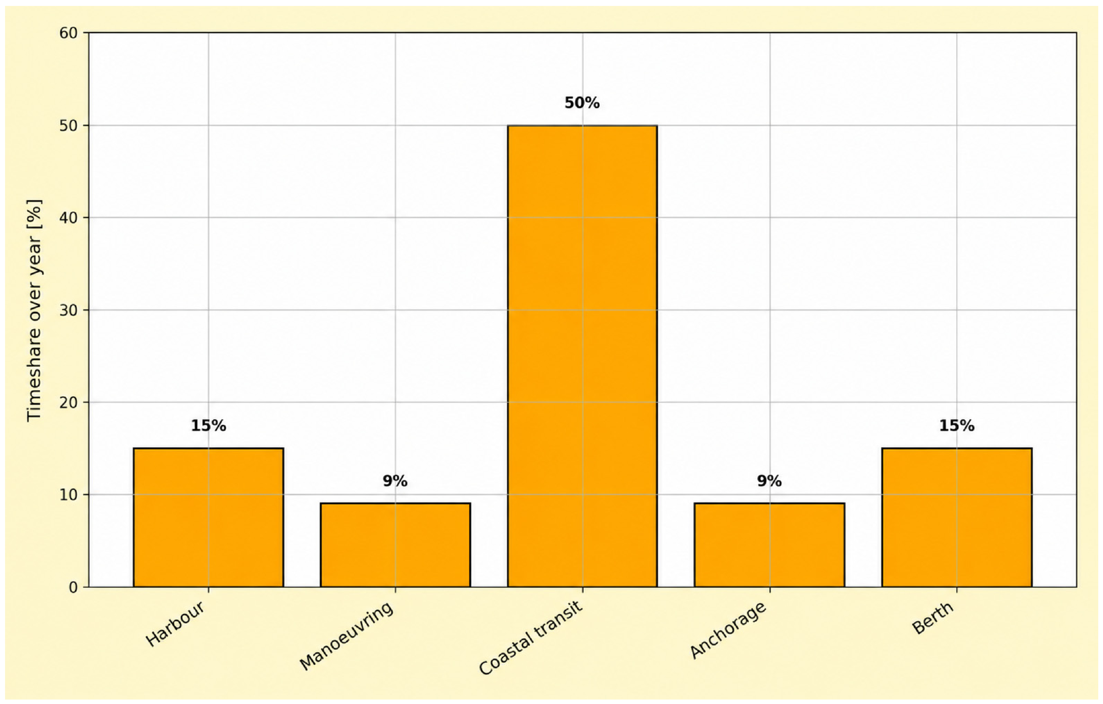
To capture this behaviour, multi-year automatic identification system (AIS) data (position, speed-over-ground, course) are fused with logbook records (departure/arrival times, cargo condition) and, where available, onboard monitoring data (propulsion power, auxiliary loads) to reconstruct time-resolved operating profiles. First, the AIS track is segmented into voyages and individual legs using distance and time gaps. Each time step is then assigned to an operating mode (harbour, manoeuvring, coastal transit, anchorage, berth) based on speed and proximity-to-port thresholds, yielding a time-at-mode histogram as illustrated schematically in
Figure 1. This representation quantifies how much time the vessel spends in low-load and port-related modes, where hybridisation is expected to be most beneficial.
Figure 1 presents the time-at-mode distribution of the case-study coastal cargo vessel, showing that the vessel spends a substantial proportion of its annual operation in coastal transit and low-load port-related modes, which supports the need for hybrid propulsion optimisation.
For each voyage, the vessel speed
V(
t) and environmental data (current, wind, sea state, if available) are combined with a calm-water resistance model and a propeller open-water curve to estimate the required propeller shaft power. Assuming a single-screw arrangement and neglecting higher-order hull–propeller–rudder interaction effects, the instantaneous effective power is approximated as Equation (1):
where
RT is the total hydrodynamic resistance. The mechanical power at the propulsion motor shaft is then given by Equation (2):
with
ηH,
ηR and
ηS denoting hull, rudder and shaft efficiencies, respectively. These relations map the reconstructed speed profile to a time-varying propulsion power demand, which directly drives the hybrid power-flow and optimisation models.
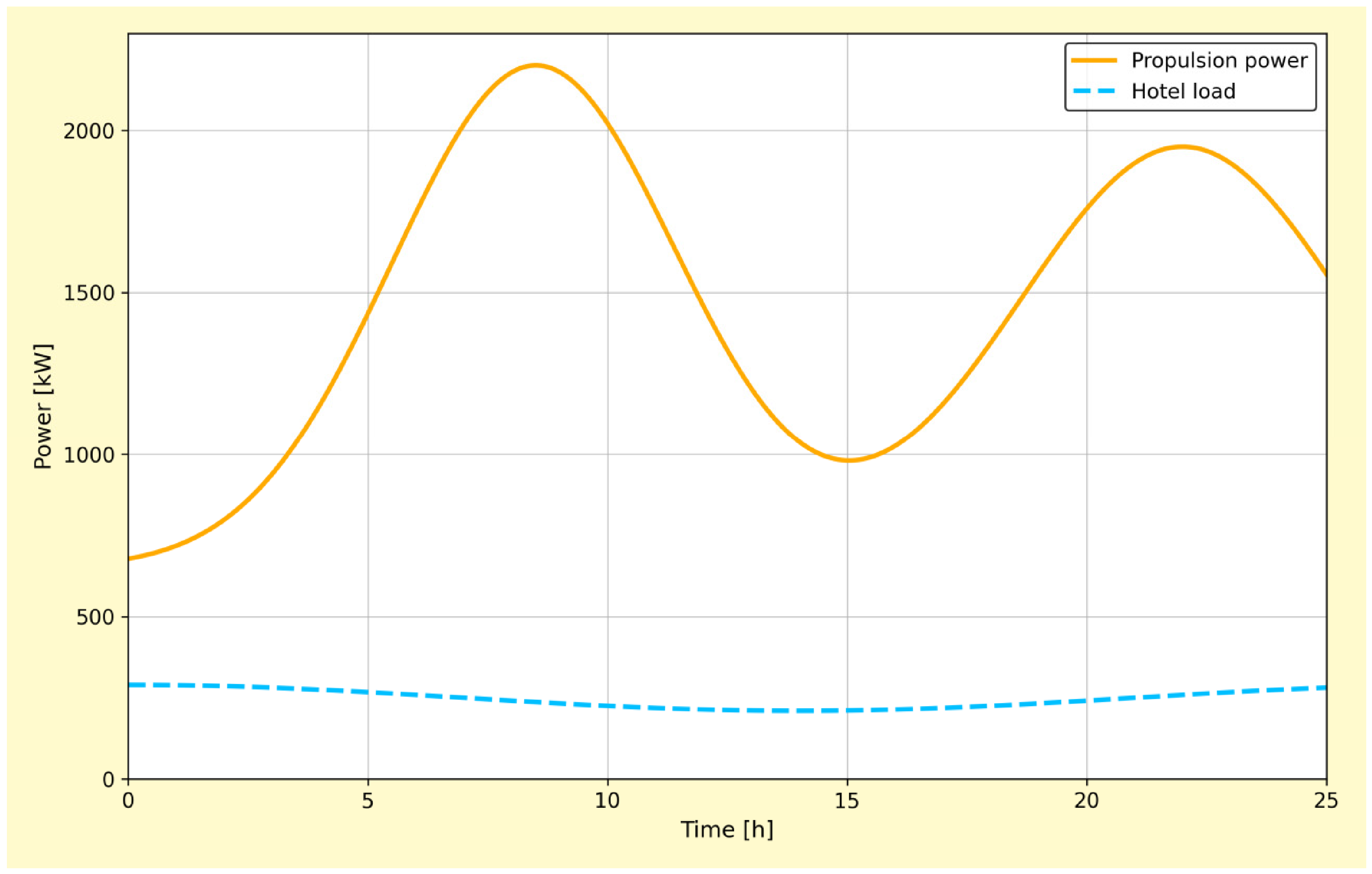
Figure 2 shows a representative reconstructed propulsion power and hotel load profile for one round trip, which serves as input to the hybrid electric propulsion system model introduced in
Section 3.2. The simultaneous representation of propulsion and hotel loads is essential for assessing how the HEPS shares power between engines and ESS across operating modes.
For clarity, the main symbols used in the following subsections are summarised in
Table 1. This notation is used consistently in the component and cost models and later in the optimisation framework.
The power curve shown in
Figure 2 is not a qualitative illustration, but a 24 h typical voyage profile generated from measured data of the target route (Dalian–Shanghai) based on the AIS data reconstruction algorithm described in
Section 5.2.
3.2. Hybrid Electric Propulsion Architecture and Component Models
3.2.1. Propulsion Architecture and DC Grid
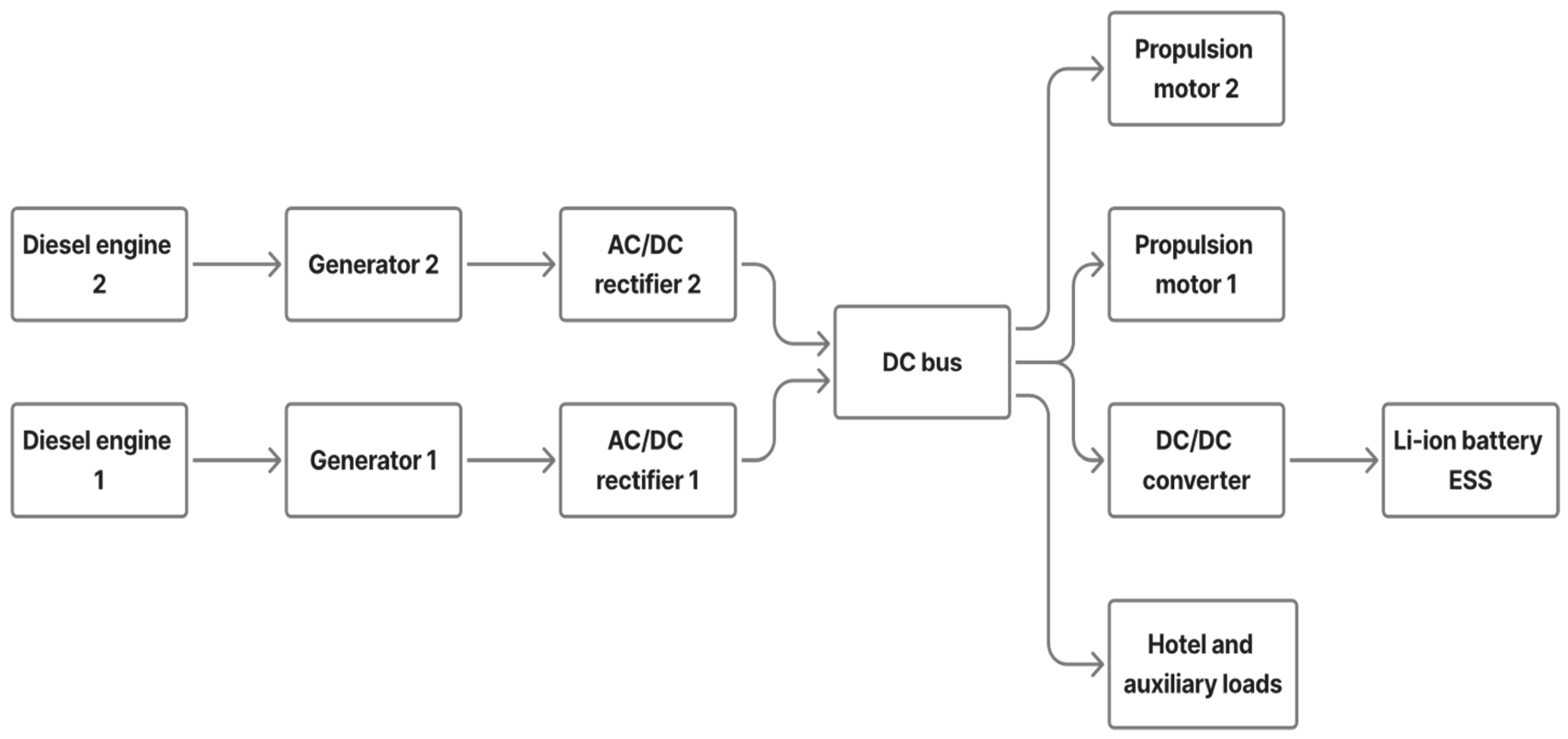
The hybrid electric propulsion system (HEPS) adopts a DC-based distribution architecture, forming an onboard microgrid that supplies propulsion and hotel loads.
Figure 3 schematically depicts the main components: two medium-speed diesel engines driving synchronous generators, a DC bus, propulsion motors, a lithium-ion battery energy storage system (ESS), and power electronic converters (rectifiers, inverters, DC/DC converters). The DC grid enables flexible power sharing between engines and the ESS, engine-off operation in low-load conditions, and all-electric operation in ports and emission-control areas, as widely advocated in recent HEPS studies [
11,
17]. This architecture provides the degrees of freedom that the optimisation exploits when allocating power between the thermal and electrical subsystems.
The sizes of the main engines and ESS are design variables in the upper-level optimisation, while the remaining components are scaled according to these sizes using manufacturer data and efficiency maps. Conversion losses in generators, motors, and converters are represented through power-dependent efficiency models incorporated into the time-domain simulation, ensuring that the cost and emission calculations reflect realistic conversion performance.
3.2.2. Engine Fuel Consumption and Emission Model
Each diesel generator set is characterised by a steady-state brake-specific fuel consumption (BSFC) map as a function of power and speed, provided by the manufacturer and stored as a lookup table. For a given time-domain power dispatch
Peng(
t) resulting from the energy management strategy (EMS), the total mass of fuel consumed over a voyage is
where BSFC is in kgkWh
−1 and
Peng in kW, yielding
mfuel in kg, following the formulation in Chen et al. [
32]. Equation (3) links the lower-level power split to fuel use and thus directly enters the life-cycle cost calculation.
Emissions of pollutant
j (e.g., NO
x, SO
x, CO, PM) are computed using power-dependent emission factors EF
j,
with
Ej in grams and EF
j in gkWh
−1. Total GHG impact is expressed as CO
2-equivalent emissions using standard 100-year global warming potentials, enabling consistent comparison of alternative designs in environmental terms.
3.2.3. Battery Equivalent Circuit and State-of-Charge Model
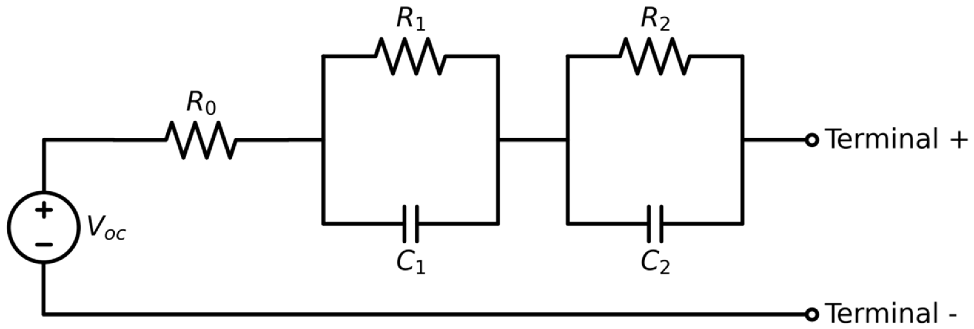
The lithium-ion ESS is modelled using a second-order equivalent-circuit model, capturing ohmic, electrochemical, and concentration overpotentials. As shown in
Figure 4, the model consists of an open-circuit voltage
Voc (SOC), an ohmic resistance
R0, and two resistor–capacitor (RC) branches (
R1,
C1) and (
R2,
C2). This level of detail is sufficient to capture the main dynamic and efficiency effects relevant for voyage-level optimisation without resorting to full electrochemical models.
The instantaneous voltage drop across the ohmic resistance is
where
I(
t) is the battery current (positive for discharge). The dynamics of the RC branches are governed by
and the terminal voltage is
The state of charge (SOC) is updated using Coulomb counting,
where
Qnom is the nominal cell capacity. The ESS power
Pess(
t) is linked to
Vbat(
t) and
I(
t) through
with an appropriate sign convention and converter efficiencies applied in the DC grid model. Together, Equations (8)–(10) determine how EMS decisions translate into SOC trajectories and conversion losses, which are critical for both performance and degradation.
3.2.4. Battery Degradation Model
Battery lifetime is a critical driver of total life-cycle cost and depends strongly on operating conditions. Following Bloom et al. [
25], Wang et al. [
26], and Chen et al. [
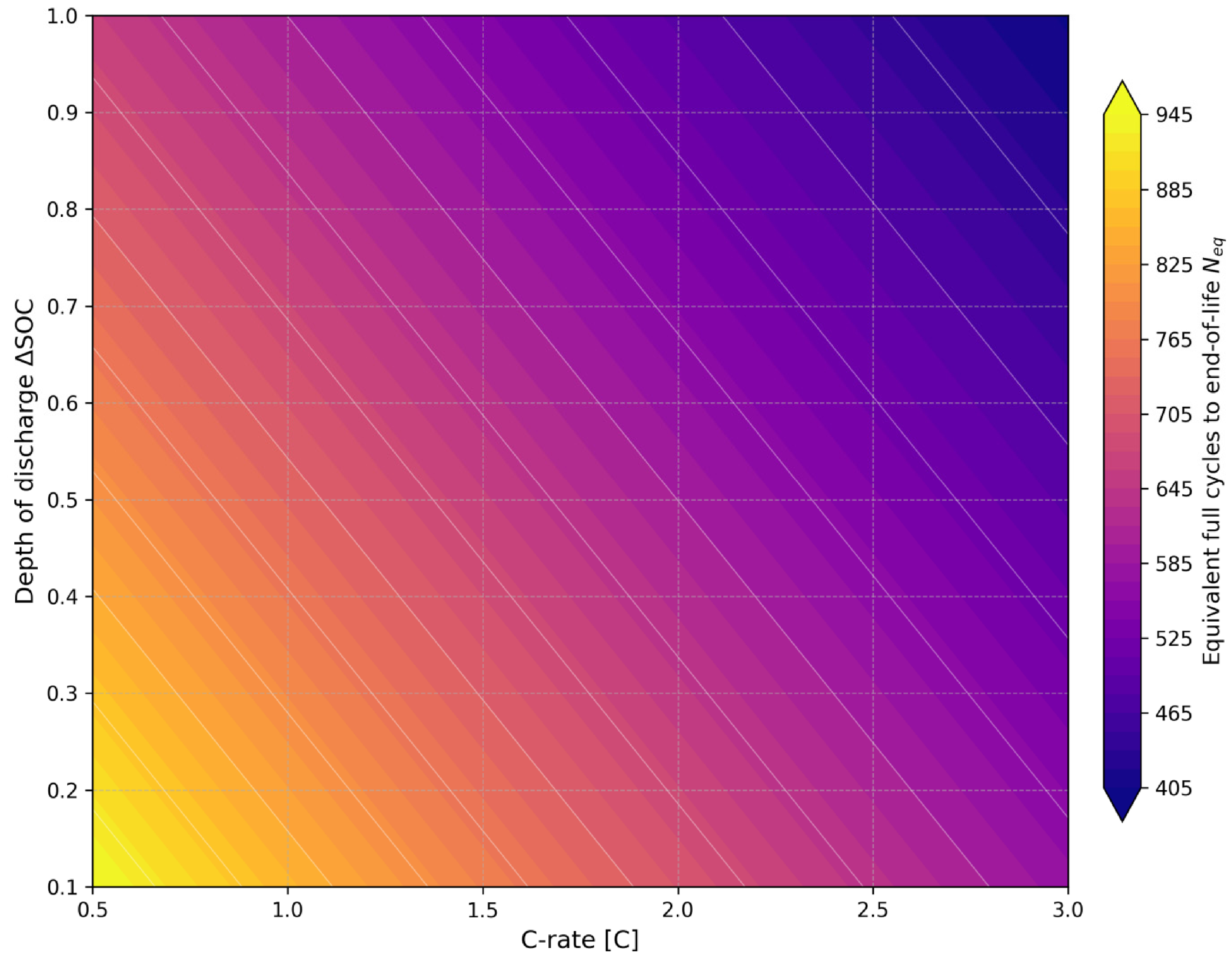
27], capacity loss is modelled as a function of temperature, C-rate, and charge throughput using an Arrhenius-type relationship. For system-level optimisation, the detailed degradation model is evaluated offline and used to construct a lookup surface of equivalent full cycles to end-of-life
Ncyc as a function of C-rate and depth of discharge ∆SOC (
Figure 5). This surface is then queried during the optimisation to estimate ESS lifetime and replacement timing under a given control policy, without solving the full electrochemical model online. The cumulative capacity loss of the battery
is expressed as
, where
is the cumulative discharge capacity and
is the power-law factor. This study strictly defines that the battery reaches the end-of-life (EOL) criterion when its available capacity drops to 80% of the nominal capacity, triggering the replacement cost calculation in the upper model.
For the present study, battery temperature is assumed to be maintained within a specified range by a thermal management system, so that the temperature dependence can be represented by an effective average value. The degradation model thereby links the lower-level control trajectories (C-rates and SOC excursions) to upper-level economic decisions via expected ESS lifetime, allowing the optimisation to trade short-term fuel savings against long-term replacement costs.
3.2.5. Life-Cycle Cost Model
To evaluate alternative propulsion system designs over the vessel’s service life, a life-cycle cost (LCC) model is formulated, extending Chen et al. [
32] to the coastal cargo context and explicitly incorporating degradation-driven ESS replacements. The LCC comprises capital cost, operational cost, and residual (salvage) value:
all discounted to a reference year using net-present-value (NPV) analysis.
Let
Ct denote the net cash flow in year
t and
r the real discount rate. The NPV of a stream of costs over a lifetime of
Ny years is
Equations (11) and (12) define the economic objective that the upper-level optimisation seeks to minimise.
Capital and reinvestment cost: The capital cost includes engines, the ESS, and hybridisation-related components (generators, motors, converters):
where
Ceng and
Cess are proportional to installed engine power
Peng,max and ESS energy capacity
Eess, and
Chyb aggregates the cost of additional electrical equipment scaled with rated power. Because the ESS lifetime may be shorter than the vessel lifetime, reinvestment cost
Crin accounts for battery replacements at times determined by the degradation model, discounted to present value. This explicitly couples operating strategy, degradation, and capital expenditure.
Operational and maintenance cost: Operational cost includes fuel and engine maintenance:
The yearly fuel cost Cfuel,t is obtained from the aggregated voyage-level fuel consumption mfuel,t given by Equation (3), and maintenance cost Cmaint,t is approximated as proportional to cumulative engine operating hours and installed power, using coefficients derived from fleet statistics and manufacturer guidelines. This structure allows the optimisation to capture both direct fuel savings and indirect maintenance benefits of hybrid operation.
Residual value. At the end of the vessel’s lifetime, the residual value of the ESS (if it has remaining capacity above a secondary-use threshold) and other components is represented as
where
pres is the unit salvage price and
Eres is the remaining usable ESS capacity inferred from the degradation model. The minus sign reflects a credit (negative cost). This term enables the framework to value partially degraded ESSs at end-of-life rather than assigning zero residual worth.
The LCC model in Equation (11) is evaluated for each candidate combination of engine and ESS sizes and associated control policy, providing the upper-level objective for the bi-level optimisation described in
Section 4. In this way, component sizing, operational behaviour, and degradation-driven replacement dynamics are consistently linked to long-term economic performance for hybridised coastal cargo vessels.
4. Bi-Level Integrated Optimisation Framework
This section formulates the integrated design and control optimisation problem for the hybrid electric propulsion system (HEPS) of the coastal cargo vessel, building on the models in
Section 3. A bi-level, nested structure is adopted, in which the upper level determines key component sizes, while the lower level computes optimal energy management policies along the reconstructed real-world operating profiles. The overall objective is to minimise life-cycle cost (LCC), with environmental emissions serving as key evaluation metrics over the vessel lifetime, subject to technical and operational constraints.
4.1. Bi-Level Problem Structure
The hybrid design problem is decomposed into a sizing layer (upper level) and an operational control layer (lower level). The sizing layer selects the total installed diesel generator power and the nominal ESS capacity, whereas the control layer optimises the power split between engines and ESS for each route and operating mode, using the power-demand profiles derived in
Section 3.1 and the component models in
Section 3.2.
Table 2 summarises the roles of the two levels. In compact form, the bi-level problem can be expressed as
represents the optimal lower-level control sequence for a given design, whereas
xup is the upper-level design vector,
cℓ the lower-level control sequence,
Fup the upper-level LCC/emission objective and
flow the lower-level voyage cost for a given design.
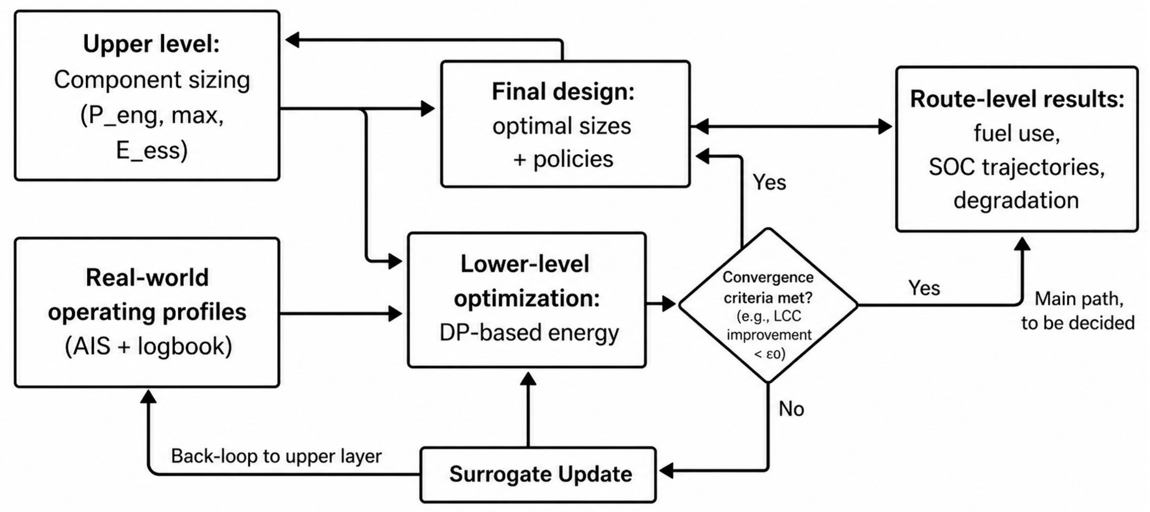
Figure 6 illustrates the interaction between the upper-level sizing loop and the lower-level energy management optimisation for the set of real-world operating profiles. Each candidate design from the upper level is evaluated by solving a lower-level control problem for all representative voyages.
4.2. Upper-Level Component Sizing
The upper level determines the optimal engine rating and ESS capacity that minimise the LCC over the vessel lifetime while respecting bounds from classification rules and machinery layout. Using the LCC formulation in
Section 3.2.5 the upper-level problem can be written as subject to lower and upper bounds on
Peng,max and
Eess. Here,
c∗ℓ(
xup) denotes the optimal control policy obtained from the lower level for design
xup.
Each evaluation of
Fup(
xup) requires a full simulation of the HEPS model over the representative operating profiles and a complete solution of the lower-level control problem. The resulting black-box objective is expensive to evaluate, so a surrogate-assisted global optimisation strategy is adopted, similar in spirit to Chen et al. [
32]. The main steps are summarised in
Table 3.
For a candidate design
x, the Expected Improvement (EI) criterion is defined as
The design space is 2-dimensional, and the search boundaries of decision variables
and
are shown in
Table 3. No integer variables are introduced in this study to maintain the continuity of the surrogate model search. For infeasible design points that fail to meet the voyage power demand or violate SOC constraints, the system marks them by assigning a large penalty value (
). The population-based optimizer used is the genetic algorithm (GA), with a population size of 50 and a maximum number of iterations of 100. The convergence criterion is defined as the relative change in the optimal LCC value within 20 consecutive generations being less than
.
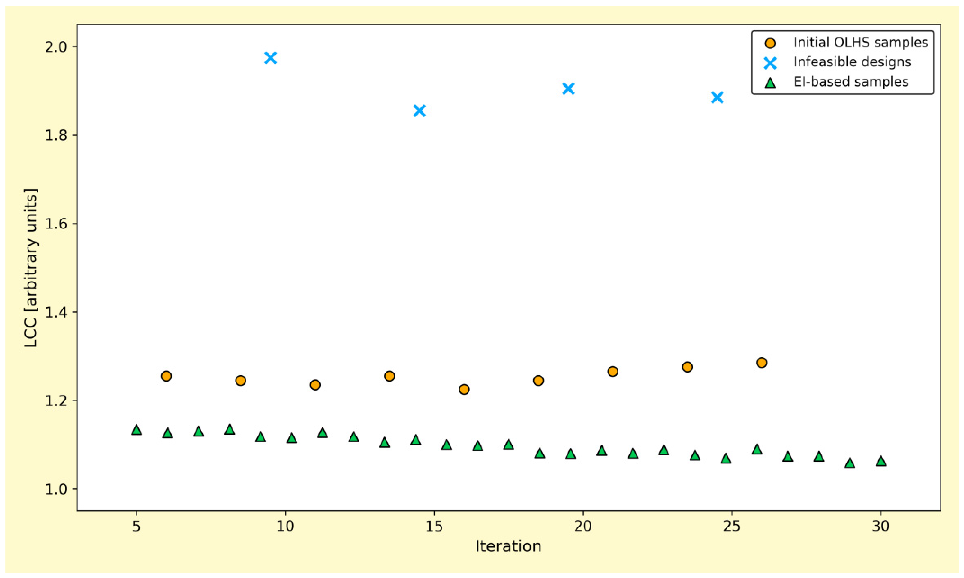
Where Y(x) is the surrogate-predicted LCC treated as a Gaussian random variable and ymin is the best LCC observed so far. A genetic algorithm (GA) is employed to locate the design candidates that maximise the EI(x) at each iteration to locate designs that maximise EI(x) at each iteration, guiding the sampling towards promising regions of the design space.
Figure 7 qualitatively illustrates the surrogate-assisted search process, showing how initial OLHS samples are progressively refined by EI-driven sampling to converge on the most favourable regions in terms of LCC.
4.3. Lower-Level Dynamic Energy Management
For a given design
xup, the lower-level problem computes the optimal energy management strategy along each time-resolved operating profile. The aim is to determine how propulsion and hotel power demand
Pdem(
k) is shared between engines and ESS so as to minimise fuel use and battery degradation while respecting technical and operational constraints derived from
Section 3.2.
4.3.1. Objective and Decision Variables
The lower-level cost functional aggregates fuel consumption and degradation-related penalties over a voyage in discrete time:
where
kfuel,k and
kdeg,k are scaled fuel and degradation rates at time step
k, ∆
t is the time step, and
a1,
a2 are weighting coefficients balancing short-term savings and long-term ESS life. The weights
and
correspond to the real-time fuel unit price and the unit capacity degradation cost (Amortised Replacement Cost) calculated based on the degradation model in
Section 3.2.4, respectively. In this way, the lower-level power distribution decision is strictly consistent with the upper-level life-cycle cost (LCC) objective function in logic, thus eliminating the subjectivity of manual parameter tuning.
Table 4 summarises the main decision variables, states, inputs, objective, and constraints of the lower-level problem. This compact description mirrors the component-level definitions in
Section 3 and highlights how the EMS optimisation interfaces with the physical models.
4.3.2. Dynamic Programming Implementation
Dynamic programming (DP) is employed to solve the lower-level problem for each operating profile. The time horizon is discretised into
T steps of length ∆
t, and the battery SOC is discretised over a finite grid, so that each system state is represented by a pair (time index, SOC level). For each time step and SOC grid point, the algorithm evaluates a finite set of admissible control actions (ESS power set-points) that satisfy the power balance and the constraints summarised in
Table 4 (SOC bounds, C-rate limits, and power limits for engines, motors, and ESS).
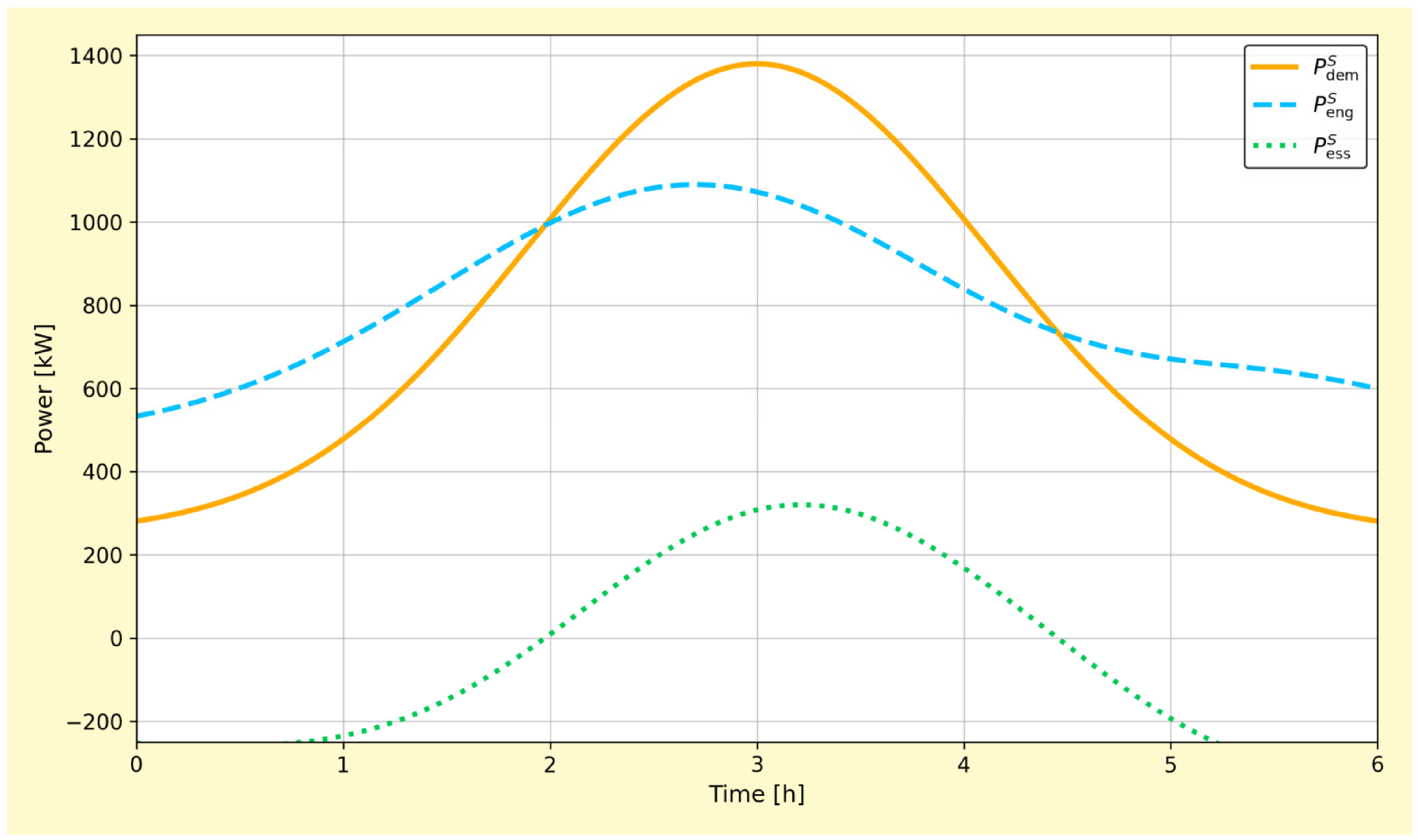
Starting from the terminal step, a backward recursion computes the cost-to-go function by combining the instantaneous fuel and degradation cost at each step with the cost-to-go of the successor state. The optimal control at each state is the one that minimises this sum while keeping the SOC within its admissible range and enforcing the end-of-voyage SOC consistency. Once the backward pass is complete, a forward simulation along the actual operating profile recovers the optimal power split trajectory, yielding the engine and ESS power histories used to evaluate fuel consumption, battery cycling severity, and life-cycle cost for each candidate HEPS design.
Figure 8 illustrates an example of optimal power split for a representative voyage. The ESS covers low-load harbour and manoeuvring phases, provides peak shaving during coastal transits, and is recharged while the engine operates in high-efficiency regions. This behaviour reflects the trade-off between fuel savings and battery ageing encoded in Equation (19). In the DP implementation, the time step Δt is set to 60 s. The SOC state space is uniformly discretized into 140 grid points within the range of [0.2, 0.9]. The discrete step size of the control variable (engine power) action set is 10 kW. On a computing platform equipped with a 3.2 GHz processor, the average solution time for a single-voyage DP problem is about 45 s, which ensures the feasibility of performing hundreds of lower-level evaluations during the surrogate model iteration.
4.4. Combined Bi-Level Problem
Combining the upper- and lower-level formulations, the integrated optimisation problem for the coastal cargo vessel HEPS can be summarised as follows:
Upper level: Search over engine rating and ESS capacity to minimise LCC and emissions, using a surrogate-assisted global optimisation that repeatedly calls the lower-level DP solver for all representative operating profiles.
Lower level: For each candidate design and route-specific operating profile, compute an optimal power split sequence that satisfies all dynamic and operational constraints while minimising fuel and degradation cost.
The surrogate-based bi-level optimisation framework shown in
Figure 6 is applied across the set of real-world operating profiles derived in
Section 3.1. The outcome is a set of optimal engine and ESS sizes, together with route-dependent energy management policies, that jointly minimise LCC and emissions while preserving the required dynamic performance of the coastal cargo vessel.
5. Case Study and Numerical Setup
This section describes the case-study configuration and numerical setup used to evaluate the proposed bi-level optimisation framework. The aim is to provide a realistic yet tractable context for assessing hybridisation benefits and design trade-offs for coastal cargo vessels.
5.1. Vessel and Route Description
This case study focuses on a representative medium-sized coastal general cargo ship active in the Bohai Bay area (Dalian–Yantai route). The ship has a coastal service area class notation from the China Classification Society (CCS). The main engine prototype is two medium-speed four-stroke diesel engines with a rated power of 3000 kW each. The typical one-way sailing distance is 90–110 nautical miles, including frequent port entry and exit manoeuvres and short-term stays at anchorages, which pose typical demands for the peak-shaving and valley-filling function of the hybrid power system.
The vessel operates on a small network of regular coastal services, comprising repeated round trips between two or three ports with typical voyage durations of one to several days. The routes involve combinations of harbour manoeuvring, sheltered coastal transits, and occasional waiting at anchor due to port congestion. This operational context is characteristic of domestic and short-sea trades targeted for early deployment of hybrid and electric technologies, and it motivates the chosen design space: the mechanical plant provides the reference installed power, while the hybrid diesel generator and ESS ranges in
Table 5 define the feasible region for the upper-level sizing problem and the operating envelope for the lower-level energy management strategy.
5.2. Data Processing and Operating Profiles
Multi-year AIS data for the vessel (position, speed-over-ground, course over ground) are combined with logbook information (departure and arrival times, loading condition) to reconstruct time-resolved operating profiles, following the methodology outlined in
Section 3.1. The AIS track is segmented into individual voyages using time and distance gaps, and each time stamp is classified into one of five operating modes (harbour, manoeuvring, coastal transit, anchorage, berth) based on speed and proximity-to-port thresholds.
The resulting time-at-mode distribution over a representative year is depicted in
Figure 1, highlighting the substantial fractions of time spent in low-load harbour and port-related modes where hybrid operation is expected to be advantageous. For each voyage, vessel speed and, where available, environmental data are mapped to effective propulsion power demand via Equations (1) and (2), and combined with empirically derived hotel load estimates to obtain the total electrical load profile. A typical reconstructed propulsion-plus-hotel power profile for a round trip is shown in
Figure 2. These profiles form the input to the lower-level dynamic energy management optimisation for each candidate HEPS design. This study extracted AIS data of the ship for a total of 24 months from 2021 to 2022, covering more than 120 complete voyages. The average sampling resolution of the original data is 3 min. For data segments missing for more than 15 min, linear interpolation or speed extrapolation is used for repair. The operating mode classification thresholds are defined as: speed
kn and distance to dock < 200 m for berthing mode;
kn for manoeuvring mode;
kn for coastal-cruising mode. The final optimisation process is performed based on five sets of statistically representative typical operating profiles extracted from all samples to ensure that the results are both universal and computationally efficient.
5.3. Model Parameterisation
The component and economic models introduced in
Section 3 are parameterised for the case-study vessel as follows. Engine BSFC and emission maps used in Equations (3) and (4) are derived from manufacturer data for a medium-speed marine diesel generator set of appropriate rating and scaled in accordance with the selected
Peng,max. Generator, motor, and converter efficiencies in the DC grid (
Figure 3) are represented by power-dependent curves calibrated to typical marine equipment in the same power range.
The lithium-ion ESS model (Equations (5)–(10)) is parameterised using cell-level data (open-circuit voltage curve, internal resistances, RC time constants) and scaled to the nominal energy capacity
Eess. Battery degradation parameters for the cycle-life surface in
Figure 5 are obtained from laboratory test data consistent with maritime ESS products and projected to pack level using standard scaling assumptions. Economic parameters for the life-cycle cost modelinclude unit costs for engines and ESS, hybridisation-related equipment costs, diesel fuel price trajectories, maintenance cost coefficients, discount rate, and vessel and ESS lifetimes. These are collected in dedicated parameter tables (e.g., vessel particulars, ESS data, economic assumptions) to facilitate scenario analysis and sensitivity studies (
Table 6).
5.4. Scenario Definition
To assess the impact of hybridisation and the proposed optimisation framework, several design and operation scenarios are defined:
Baseline mechanical configuration (MECH): A conventional mechanically driven propulsion plant with fixed installed engine power sized according to traditional design practice for the case-study routes. No ESS is installed; engine loading follows a rule-based speed schedule without hybrid support.
Rule-based hybrid configuration (HYB-RB): A hybrid electric propulsion system with engine and ESS sizes selected by simplified heuristic rules (e.g., fixed percentage engine downsizing and ESS sized for a prescribed electric-only harbour duration). Power split follows a predefined rule-based energy management strategy (e.g., charge-sustaining with peak shaving) rather than optimisation.
Optimised hybrid configuration (HYB-OPT): A HEPS whose engine rating
Peng,max and ESS capacity
Eess are obtained from the surrogate-assisted bi-level optimisation described in
Section 4. Lower-level control uses DP-based energy management with degradation-aware cost weighting, as in Equation (19).
Sensitivity and robustness cases: Additional runs explore the influence of key assumptions, such as alternative fuel price trajectories, ESS cost projections, modified operating patterns (e.g., higher port congestion leading to longer anchorage times), and different degradation weightings a2 in Equation (19). These scenarios assess how robust the optimised designs are to plausible variations in economic and operational conditions.
For each scenario, the HEPS model is simulated over the set of representative operating profiles derived in
Section 5.2, and the resulting fuel consumption, emissions, ESS degradation, and life-cycle cost are computed.
The comparison between MECH, HYB-RB, and HYB-OPT configurations provides a quantitative basis for evaluating the benefits of hybridisation and the added value of integrated, degradation-aware design and control optimisation for coastal cargo vessels.
6. Results and Discussion
This section presents and discusses the results obtained by applying the surrogate-assisted bi-level optimisation framework of
Section 4 to the case-study coastal cargo vessel defined in
Section 5. The focus is on comparing conventional and hybrid configurations, interpreting the optimal sizing outcomes, assessing the influence of route patterns, and exploring the trade-offs between fuel savings and battery degradation under different assumptions. Where appropriate, the performance of the proposed approach is contrasted with representative baselines from the literature.
6.1. Baseline Versus Hybrid Configurations
The first comparison is between the conventional mechanical baseline (MECH), the rule-based hybrid configuration (HYB-RB), and the optimised hybrid configuration (HYB-OPT) defined in
Section 5.4. For each configuration, the propulsion plant is simulated over the set of representative operating profiles derived in
Section 5.2, and the resulting fuel use, emissions, and life-cycle cost (LCC) are evaluated using the models.
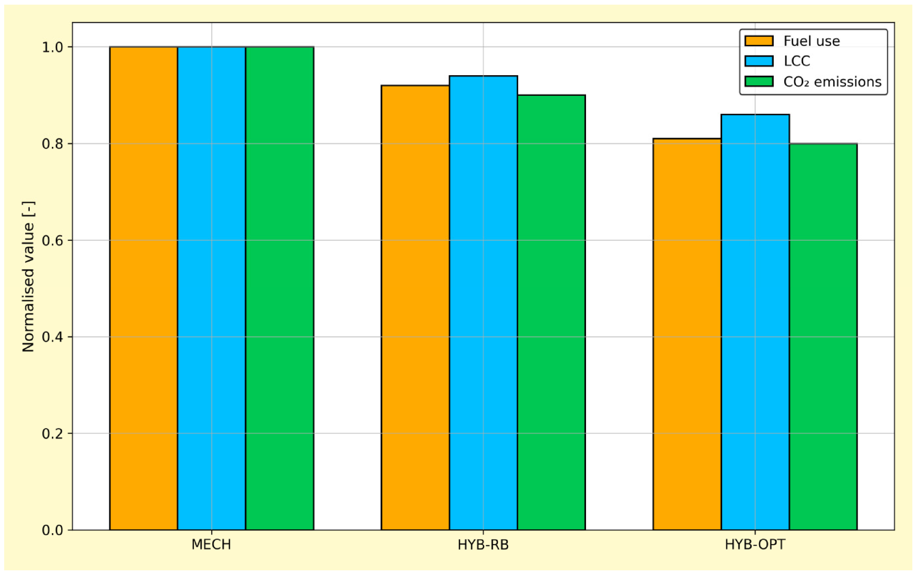
Table 7 summarises the relative performance of the three configurations, normalised with respect to the MECH baseline (MECH = 1.00 for each metric). HYB-RB reduces fuel use by about 8% and LCC by 6% relative to MECH, due to engine load levelling and partial electric operation. HYBOPT consistently outperforms both MECH and HYB-RB, achieving approximately 19% fuel savings, 14% LCC reduction, and 20% CO
2 reduction relative to MECH, and a further 12% fuel and 9% LCC reduction relative to HYB-RB.
Figure 9 provides a visual comparison of normalised fuel consumption, LCC, and CO
2 emissions, highlighting the additional benefit obtained by joint optimisation of sizing and control rather than relying on heuristic hybridisation rules.
The rule-based hybrid (HYB-RB) benefits from straightforward engine load levelling and electric harbour operation but does not fully exploit the available flexibility. In contrast, HYB-OPT uses the bi-level framework to identify engine ratings and ESS capacities that place the generators in favourable operating regions and employs dynamic programming (DP) to allocate ESS power over the voyage. The resulting optimal power split is illustrated in
Figure 8, where the ESS primarily supplies low-load harbour and manoeuvring phases, assists with peak shaving during coastal transit, and is recharged when the engine operates in high-efficiency regions. From a dynamic performance perspective, the optimised hybrid solutions satisfy all propulsion power and SOC constraints for the considered profiles, indicating that the design choices identified by the upper-level search are compatible with the operational requirements of the case-study vessel.
6.2. Optimal Sizing Outcomes
The surrogate-assisted upper-level optimisation in
Section 4.2 converges to a region in the (
Peng,max,
Eess) design space where further improvements in LCC become marginal. The EI-based search history in
Figure 7 shows how the initial OLHS designs are progressively refined as the surrogate is updated with new samples.
Table 8 reports the resulting sizes for
Peng,max and
Eess for the three configurations. The MECH baseline installs 6.0 MW of total engine power (2 × 3000 kW) with no ESS. The heuristic hybrid (HYB-RB) reduces total engine rating to 2.6 MW and adds a 1.0 MWh ESS sized for limited harbour operation and peak shaving. The optimised configuration (HYB-OPT) further reduces installed engine power to 2.3 MW (about 23% downsizing relative to MECH) and increases ESS capacity to 1.6 MWh. This combination provides sufficient storage to cover repeated low-load harbour and manoeuvring phases and support peak shaving during coastal transit, without incurring excessive capital and replacement costs.
Too small an ESS leads to insufficient flexibility for engine off-loading and reduced fuel and maintenance savings; conversely, very large ESS capacities increase capital and reinvestment costs without proportional operational benefits. The bi-level framework thus identifies a “sweet spot” where the marginal value of additional ESS capacity is balanced by its cost and degradation. Compared with the heuristic HYB-RB sizing, HYB-OPT allocates less excess engine power and a larger ESS capacity, reflecting the fact that the DP-based EMS can exploit more aggressive charging and discharging strategies while still respecting SOC and C-rate constraints. The EI-guided sampling in
Figure 7 further indicates that the surrogate concentrates evaluations in this region, confirming its relevance as a robust optimum.
6.3. Effect of Route Patterns and Operating Modes
To investigate the influence of operational patterns, the optimisation and subsequent simulations are repeated for different subsets of the route network (e.g., routes with longer transit legs versus routes with more frequent port calls). The time-at-mode distributions in
Figure 1 and the associated power profiles in
Figure 2 show substantial variation in the relative contributions of harbour, manoeuvring, coastal-transit, anchorage, and berth modes.
Table 9 compares the performance of HYB-OPT across two representative route clusters: a transit-dominated pattern with long coastal legs and relatively short port stays, and a port-dominated pattern with frequent port calls and extended berth and anchorage durations. For the transit-dominated pattern, the optimisation converges to an ESS capacity of about 1.4 MWh, yielding fuel and LCC reductions of 16% and 11% relative to MECH on that route subset. For the port-dominated pattern, the optimal ESS size increases to about 1.8 MWh, and fuel and LCC reductions increase to 21% and 16%, respectively, due to the larger benefit of all-electric harbour and berth operation and extended engine-off periods.
These observations underline the importance of using route-specific, multi-year operating profiles rather than stylised duty cycles: the optimal hybrid configuration and its expected benefits are sensitive to the detailed mix of operating modes and their temporal patterns. In particular, higher fractions of low-load harbour and berth modes increase the economic value of additional ESS capacity, while routes dominated by long transits favour moderate ESS sizes combined with efficient engine operation. Specifically, the 120 reconstructed voyages were grouped using a K-means clustering approach based on the ratio of time spent in harbour/manoeuvring modes to total voyage duration. This yielded two distinct clusters: a ‘Transit-dominated’ group (72 voyages, average harbour-time ratio < 15%) and a ‘Port-dominated’ group (48 voyages, ratio > 35%).
6.4. Trade-Offs Between Fuel Savings and Battery Degradation
The weighting parameters a1 and a2 in the lower-level cost function (Equation (19)) control the trade-off between short-term fuel savings and long-term battery degradation. To explore this trade-off, several DP runs are performed for the same design xup but with different values of a2.
Table 10 summarises the impact of varying
a2 on fuel use, degradation, and expected ESS replacement timing, as inferred from the degradation surface in
Figure 5. For low
a2, the EMS frequently uses the ESS to absorb short-term fluctuations in power demand and aggressively shifts engine operation towards high-efficiency regions. Fuel savings relative to MECH reach about 22%, but deeper and more frequent SOC excursions accelerate capacity fade, resulting in an expected ESS lifetime of roughly 6 years and two replacements over a typical 20-year vessel lifetime.
For high a2, the EMS becomes more conservative: SOC excursions are reduced, C-rates are kept within milder ranges, and the ESS is used more sparingly. Fuel savings relative to MECH decrease to about 14%, but the expected ESS lifetime extends to around 12 years, often requiring only a single replacement. The bi-level optimisation implicitly searches over designs and policies that balance these effects, and the final HYB-OPT solutions generally correspond to intermediate a2 values where the marginal fuel saving from additional cycling is approximately offset by the marginal cost of accelerated degradation in the LCC.
6.5. Comparison with Literature Baselines
To position the proposed approach relative to existing work,
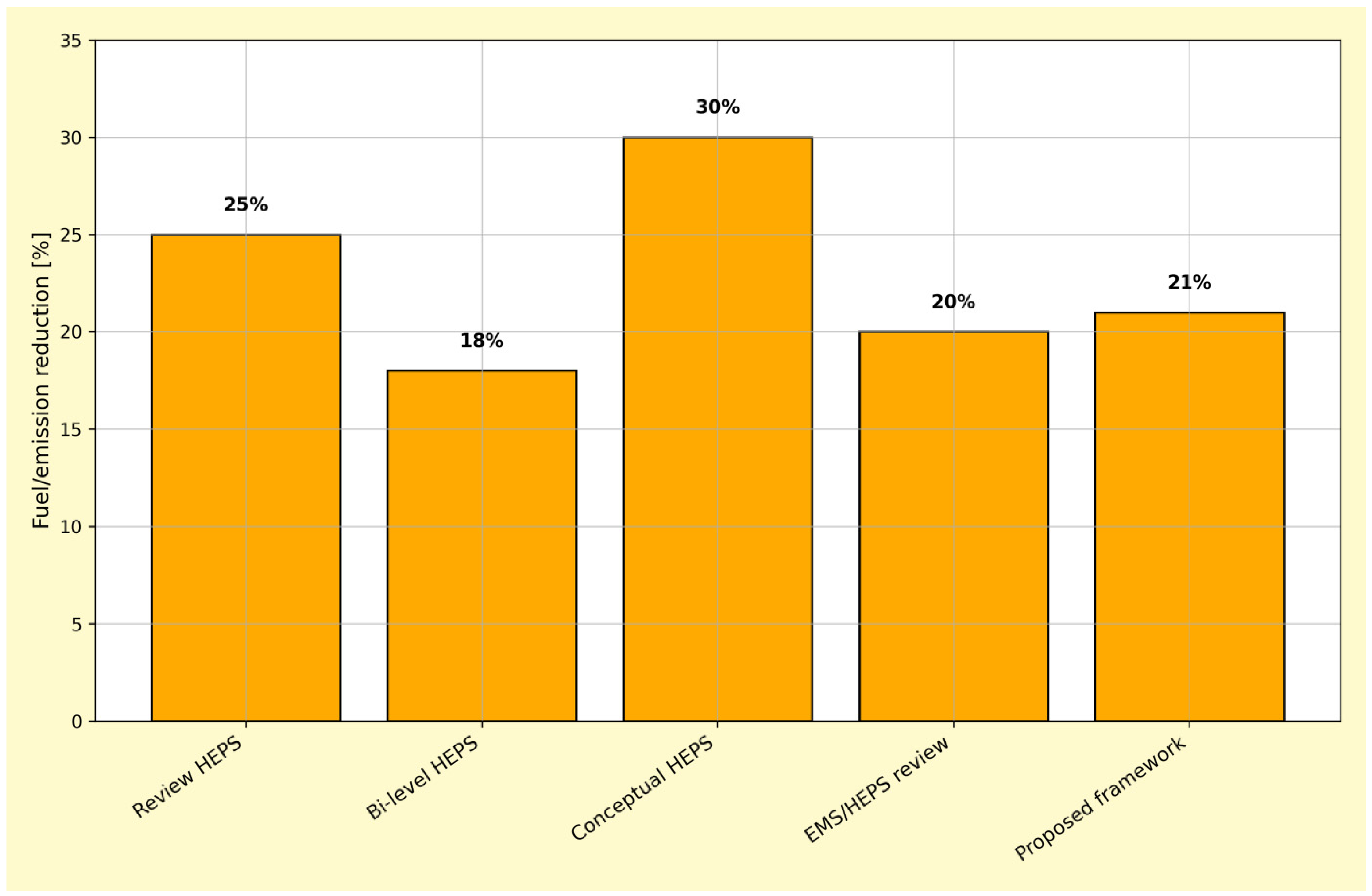
Figure 10 compares typical fuel and emission reduction levels achieved by different classes of marine HEPS models identified in the literature review (
Section 2)—including review-type HEPS concepts, bi-level HEPS formulations, conceptual HEPS designs, and recent EMS/HEPS control-oriented studies—with the AIS-based, degradation-aware bi-level framework developed in this paper. Prior contributions on tugs, ferries, and offshore vessels generally report fuel and emission reductions in the range of 10–35% under stylised or single-mission duty cycles and with limited or simplified treatment of battery degradation in life-cycle economics [
5,
6,
32,
33].
As illustrated in
Figure 10, the proposed framework delivers reductions that are competitive with, and in several cases exceed, the upper end of these ranges for the considered coastal cargo routes. More importantly, these gains arise from a combination of features that address key gaps in the existing baselines: the use of multi-year, route-specific AIS/logbook profiles instead of synthetic cycles, the explicit embedding of a degradation-aware ESS model in the LCC objective, and the surrogate-assisted bi-level optimisation that jointly tunes component sizes and dynamic energy management under realistic operating constraints. Consequently, the reported fuel and emission reductions are directly aligned with life-cycle economic performance for coastal cargo service, rather than being evaluated in isolation for a single nominal mission.
6.6. Sensitivity and Limitations
Sensitivity analyses are conducted to assess the robustness of the optimised hybrid designs to key economic and operational assumptions. Variations in fuel price trajectories, ESS cost projections, and discount rate are introduced into the LCC model. Under a high-fuel-price scenario, fuel savings translate into larger LCC reductions, and the optimal ESS capacity increases by about 10–15%. Under a low-ESS-cost scenario, the framework favours slightly larger storage capacities and more aggressive use of the ESS, with fuel reductions approaching 23% on port-dominated routes. Conversely, higher discount rates and more pessimistic ESS cost assumptions reduce the economic headroom for hybridisation and shift the optimal design closer to the MECH baseline (larger Peng,max, smaller Eess), while still maintaining a positive LCC benefit.
Several limitations of the present study should be acknowledged. First, the resistance and propulsion models used to reconstruct
Pm(
t) are simplified and do not fully capture hull fouling, extreme weather, or detailed manoeuvring dynamics. Second, the battery degradation model is based on laboratory data and represented via a stationary cycle-life surface (
Figure 5); real-world ESS performance may be influenced by factors not captured here (e.g., thermal gradients, cell-to-cell variation, ageing under complex load patterns). Third, the DP-based EMS assumes perfect knowledge of the future power profile for each voyage; while this is appropriate for offline design optimisation, real-time implementation would require predictive or rule-based approximations derived from the DP solutions.
Despite these limitations, the results demonstrate that integrating route-specific operational data, degradation-aware ESS modelling, and bi-level optimisation yields hybrid designs and control strategies that are economically and operationally attractive for coastal cargo vessels. The sensitivity analyses further indicate that these conclusions are broadly robust across a wide range of plausible fuel and ESS cost trajectories, and that the proposed framework performs competitively with, and in several respects beyond, existing HEPS design approaches reported in the recent literature.
7. Conclusions
This study has developed an integrated, model-based framework for the design and dynamic performance optimisation of hybrid electric propulsion systems (HEPSs) for coastal cargo vessels operating under real-world conditions. Building on a bi-level structure, the approach couples component sizing at the design stage with energy management at the operational stage, using route-specific operating profiles reconstructed from AIS and logbook data rather than idealised duty cycles. Within this framework, a DC-based hybrid architecture with medium-speed diesel generators, propulsion motors and a lithium-ion battery ESS is represented in the time domain and embedded in a life-cycle cost formulation tailored to coastal trades.
The bi-level formulation distinguishes clearly between long-term design choices and short-term control decisions. The upper level searches over engine rating and ESS capacity, while the lower level employs dynamic-programming-based energy management (
Figure 6) to derive power-split policies that respect SOC, C-rate and power constraints. A surrogate-assisted global optimisation strategy, combining OLHS, Kriging surrogates and an Expected Improvement criterion (
Table 3), makes this computationally tractable and ensures that candidate designs are evaluated under realistic, route-dependent operating conditions.
Application to a representative coastal cargo vessel suggests that properly sized HEPS, operated with degradation-aware energy management, can support engine downsizing, shift operation towards more favourable loading regimes, and reduce reliance on conventional mechanical propulsion in low-load and port phases. The optimisation framework clarifies trade-offs between fuel use and battery degradation, and highlights the influence of route patterns and harbour operations on preferred designs, offering guidance to shipowners and designers considering hybridisation for coastal fleets.
Future work will extend the framework to multi-objective formulations that jointly consider economic, environmental and operational criteria, and to hybrid systems including alternative fuels and shore-power integration. Robust and stochastic variants could address uncertainties in costs and operating patterns, while reduced-order control strategies derived from the dynamic programming solution could be implemented onboard and validated using hardware-in-the-loop or sea-trial data.
Author Contributions
Conceptualization, J.D. and Y.S.; methodology, J.D.; software, B.M.; validation, J.D., Y.S. and B.M.; formal analysis, Z.X.; investigation, Z.X.; resources, B.M.; data curation, B.L.; writing—original draft preparation, J.D.; writing—review and editing, Y.S.; visualization, J.D.; supervision, B.M.; project administration, Z.X.; funding acquisition, B.L. All authors have read and agreed to the published version of the manuscript.
Funding
This study received no external financial support.
Institutional Review Board Statement
Not applicable.
Informed Consent Statement
This study does not involve human subjects.
Data Availability Statement
The data and code that support the findings of this study are available from the corresponding author upon reasonable request.
Conflicts of Interest
The authors declare that they have no known competing financial interests or personal relationships that could have appeared to influence the work reported in this paper. The authors confirm that there are no conflicts of interest associated with this publication.
References
- IMO. Initial IMO Strategy on Reduction of GHG Emissions from Ships; Resolution MEPC. 304(72); International Maritime Organization: London, UK, 2018. [Google Scholar]
- International Renewable Energy Agency. A Pathway to Decarbonise the Shipping Sector by 2050; Technical Report; IRENA: Abu Dhabi, United Arab Emirates, 2021. [Google Scholar]
- Vakili, S.; Insel, M.; Singh, S.; Ölçer, A. Decarbonizing domestic and short-sea shipping: A systematic review and transdisciplinary pathway for emerging maritime regions. Sustainability 2025, 17, 7294. [Google Scholar] [CrossRef] [Scilit]
- International Transport Forum. Decarbonisation, Coastal Shipping and Multimodal Transport; Technical Report Roundtable Report 192; OECD/ITF: Paris, France, 2023. [Google Scholar]
- Geertsma, R.D.; Negenborn, R.R.; Visser, K.; Hopman, J.J. Design and control of hybrid power and propulsion systems for smart ships: A review of developments. Appl. Energy 2017, 194, 30–54. [Google Scholar] [CrossRef] [Scilit]
- Inal, O.B.; Charpentier, J.-F.; Deniz, C. Hybrid power and propulsion systems for ships: Current status and future challenges. Renew. Sustain. Energy Rev. 2022, 156, 111978. [Google Scholar] [CrossRef] [Scilit]
- Pang, B.; Liu, S.; Zhu, H.; Feng, Y.; Dong, Z. Real-time optimal control of an LNG-fueled hybrid electric ship considering battery degradations. Energy 2024, 296, 131170. [Google Scholar] [CrossRef] [Scilit]
- Gao, J.; Lan, H.; Cheng, P.; Hong, Y.-Y.; Yin, H. Optimal scheduling of an electric propulsion tugboat considering various operating conditions and navigation uncertainties. J. Mar. Sci. Eng. 2022, 10, 1973. [Google Scholar] [CrossRef] [Scilit]
- Serra, P.; Fancello, G. Towards the IMO’s GHG goals: A critical overview of the perspectives and challenges of the main options for decarbonizing international shipping. Sustainability 2020, 12, 3220. [Google Scholar] [CrossRef] [Scilit]
- Vakili, S.; Wadud, Z.; Pant, R. Port electrification maturity assessment: A case study of the Philippines. Sustain. Cities Soc. 2023, 96, 104618. [Google Scholar] [CrossRef] [Scilit]
- Guo, X.; Lang, X.; Yuan, Y.; Tong, L.; Shen, B.; Long, T.; Mao, W. Energy management system for hybrid ship: Status and perspectives. Ocean Eng. 2024, 310, 118638. [Google Scholar] [CrossRef] [Scilit]
- Kang, K.-W.; Jeon, C.-H.; Jeon, H.-M.; Kim, J.-S. Empirical study on the application of fuel cell–battery hybrid electric propulsion systems in small coastal ships. J. Korean Soc. Mar. Eng. 2019, 43, 648–654. [Google Scholar] [CrossRef] [Scilit]
- Torreglosa, J.P.; Gonzalez-Rivera, E.; Garcıa-Trivino, P.; Vera, D. Performance analysis of a hybrid electric ship by real-time verification. Energies 2022, 15, 2116. [Google Scholar] [CrossRef] [Scilit]
- Banaei, M.; Ghanami, F.; Rafiei, M.; Boudjadar, J.; Khooban, M.-H. Energy management of hybrid diesel/battery ships in multidisciplinary emission policy areas. Energies 2020, 13, 4179. [Google Scholar] [CrossRef] [Scilit]
- He, Y.; Fan, A.; Wang, Z.; Liu, Y.; Mao, W. Two-phase energy efficiency optimization for ship using parallel hybrid electric propulsion. Ocean Eng. 2021, 238, 109733. [Google Scholar] [CrossRef] [Scilit]
- Ghimire, P.; Molinas, M.; Undeland, T.M. Dynamic modeling and control of marine DC hybrid power system. IEEE Trans. Transp. Electrif. 2020, 6, 1439–1451. [Google Scholar] [CrossRef] [Scilit]
- Rafiei, M.; Boudjadar, J.; Khooban, M.-H. Energy management of a zero-emission ferry boat with a fuel-cell-based hybrid energy system: Feasibility assessment. IEEE Trans. Ind. Electron. 2021, 68, 1739–1748. [Google Scholar] [CrossRef] [Scilit]
- Kortsari, E.; Theotokatos, G.; Livanos, G.A. Evaluating the economic performance of a pure electric and diesel vessel: The case of E-ferry in Denmark. Trans. Marit. Sci. 2022, 11, 48–60. [Google Scholar] [CrossRef] [Scilit]
- Jeong, B.; Jang, H.; Lee, W.; Park, C.; Ha, S.; Kim, D.K.; Cho, N.-K. Is electric battery propulsion for ships truly a lifecycle energy solution for marine environmental protection as a whole? J. Clean. Prod. 2022, 355, 131756. [Google Scholar] [CrossRef] [Scilit]
- Peng, X.; Chen, H.; Guan, C. Energy Management Optimization of Fuel Cell Hybrid Ship Based on Particle Swarm Optimization Algorithm. Energies 2023, 16, 1373. [Google Scholar] [CrossRef] [Scilit]
- Oh, D.; Cho, D.-S.; Kim, T.-W. Design and evaluation of hybrid propulsion ship powered by fuel cell and bottoming cycle. Int. J. Hydrogen Energy 2023, 48, 8273–8285. [Google Scholar] [CrossRef] [Scilit]
- Jung, J.; Jeon, H.; Kim, H.; Kim, S. A novel approach for the systematic evaluation and optimization of performance and emissions in hybrid electric propulsion systems. J. Mar. Sci. Eng. 2025, 13, 328. [Google Scholar] [CrossRef] [Scilit]
- Liu, H.; Fan, A.; Li, Y.; Vladimir, N. Testing methods for multi-energy ship energy management systems: A systematic review. Ocean Eng. 2024, 304, 117889. [Google Scholar] [CrossRef] [Scilit]
- Kim, S.; Jeon, H. Empirical research to design rulebased strategy control with energy consumption minimization strategy of energy management systems in hybrid electric propulsion systems. J. Mar. Sci. Eng. 2025, 13, 1695. [Google Scholar] [CrossRef] [Scilit]
- Bloom, I.; Cole, B.W.; Sohn, J.J.; Jones, S.; Polzin, E.; Battaglia, V.; Henriksen, G.; Motloch, C.; Richardson, R.; Unkelhaeuser, T.; et al. An accelerated calendar and cycle life study of Li-ion cells. J. Power Sources 2001, 101, 238–247. [Google Scholar] [CrossRef] [Scilit]
- Wang, J.; Liu, P.; Hicks-Garner, J.; Sherman, E.; Soukiazian, S.; Verbrugge, M.; Tataria, H.; Musser, J.; Finamore, P. Cycle-life model for graphite-LiFePO4 cells. J. Power Sources 2011, 196, 3942–3948. [Google Scholar] [CrossRef] [Scilit]
- Chen, L.; Tong, Y.; Dong, Z. Li-ion battery performance degradation modeling for the optimal design and energy management of electrified propulsion systems. Energies 2020, 13, 1629. [Google Scholar] [CrossRef] [Scilit]
- Daigle, M.; Kulkarni, C.; Gorospe, G. Prognostics and health management for the optimization of marine hybrid energy systems. Energies 2020, 13, 4676. [Google Scholar] [CrossRef] [Scilit]
- Ünlübayir, C.; Mierendorff, U.H.; Börner, M.F.; Quade, K.L.; Blömeke, A.; Ringbeck, F.; Sauer, D.U. A data-driven approach to ship energy management: Incorporating automated tracking system data and weather information. J. Mar. Sci. Eng. 2023, 11, 2259. [Google Scholar] [CrossRef] [Scilit]
- Liu, N. Insights for China’s Carbon Market Development from the EU’s Carbon Border Adjustment Mechanism. Financ. Dev. Rev. 2022, 12, 16–25. [Google Scholar] [CrossRef]
- Choi, S.B.; Hong, S.H.; Kim, S.J. Stochastic power control strategy for hybrid electric propulsion ships using markov chain-based operational data augmentation. J. Mar. Sci. Eng. 2025, 13, 1219. [Google Scholar] [CrossRef] [Scilit]
- Chen, L.; Dong, H.; Dong, Z. Integrated system design and control optimization of hybrid electric propulsion system using a bi-level, nested approach. In Proceedings of the ASME 2019 International Design Engineering Technical Conferences and Computers and Information in Engineering Conference (IDETC/CIE), Volume 2A: 45th Design Automation Conference; ASME: New York, NY, USA, 2019; p. V02AT03A047. [Google Scholar] [CrossRef] [Scilit]
- Zhu, J.; Chen, L.; Wang, X.; Yu, L. Bi-level optimal sizing and energy management of hybrid electric propulsion systems. Appl. Energy 2020, 260, 114134. [Google Scholar] [CrossRef] [Scilit]
Figure 1.
Data-driven results from the case-study time-at-mode distribution of the coastal cargo vessel over one representative year.
Figure 1.
Data-driven results from the case-study time-at-mode distribution of the coastal cargo vessel over one representative year.
Figure 2.
Reconstructed time-domain profile of propulsion power and hotel load for a representative round-trip voyage.
Figure 2.
Reconstructed time-domain profile of propulsion power and hotel load for a representative round-trip voyage.
Figure 3.
Integrated hybrid electric propulsion architecture for the coastal cargo vessel, with dual diesel generator sets, DC bus, propulsion motors, and lithium-ion battery ESS. Arrows indicate energy flow directions.
Figure 3.
Integrated hybrid electric propulsion architecture for the coastal cargo vessel, with dual diesel generator sets, DC bus, propulsion motors, and lithium-ion battery ESS. Arrows indicate energy flow directions.
Figure 4.
Second-order equivalent-circuit model of the lithium-ion battery ESS with open-circuit voltage source Voc, ohmic resistance R0, and two RC branches (R1, C1) and (R2, C2).
Figure 4.
Second-order equivalent-circuit model of the lithium-ion battery ESS with open-circuit voltage source Voc, ohmic resistance R0, and two RC branches (R1, C1) and (R2, C2).
Figure 5.
Data-driven results from the case-study surface of equivalent full cycles to end-of-life Ncyc as a function of C-rate and depth of discharge ∆SOC for the lithium-ion ESS.
Figure 5.
Data-driven results from the case-study surface of equivalent full cycles to end-of-life Ncyc as a function of C-rate and depth of discharge ∆SOC for the lithium-ion ESS.
Figure 6.
Conceptual bi-level nested optimisation framework for integrated HEPS design: The upper level searches over component sizes, while each candidate design is evaluated by a lower-level dynamic-programming-based energy management optimisation.
Figure 6.
Conceptual bi-level nested optimisation framework for integrated HEPS design: The upper level searches over component sizes, while each candidate design is evaluated by a lower-level dynamic-programming-based energy management optimisation.
Figure 7.
Data-driven results from the case-study surrogate-assisted search history: Initial OLHS samples, infeasible designs, feasible designs, and iterative EI-based samples with corresponding LCC values.
Figure 7.
Data-driven results from the case-study surrogate-assisted search history: Initial OLHS samples, infeasible designs, feasible designs, and iterative EI-based samples with corresponding LCC values.
Figure 8.
Example of optimal power split for a representative voyage: required load Pdem, engine power Peng, and ESS power Pess obtained from the DP-based energy management strategy for a given HEPS design.
Figure 8.
Example of optimal power split for a representative voyage: required load Pdem, engine power Peng, and ESS power Pess obtained from the DP-based energy management strategy for a given HEPS design.
Figure 9.
Normalised fuel use, life-cycle cost (LCC), and CO
2 emissions for MECH, HYBRB, and HYB-OPT configurations (MECH = 1.00) (corresponding to the values in
Table 7).
Figure 9.
Normalised fuel use, life-cycle cost (LCC), and CO
2 emissions for MECH, HYBRB, and HYB-OPT configurations (MECH = 1.00) (corresponding to the values in
Table 7).
Figure 10.
Comparison of typical fuel/emission reduction achieved by different marine HEPS model classes (Review HEPS, bi-level HEPS, conceptual HEPS, EMS/HEPS review range) and the proposed AIS-based, degradation-aware bi-level design framework for the coastal cargo vessel.
Figure 10.
Comparison of typical fuel/emission reduction achieved by different marine HEPS model classes (Review HEPS, bi-level HEPS, conceptual HEPS, EMS/HEPS review range) and the proposed AIS-based, degradation-aware bi-level design framework for the coastal cargo vessel.
Table 1.
Main symbols used in the modelling of the hybrid electric propulsion system.
Table 1.
Main symbols used in the modelling of the hybrid electric propulsion system.
| Symbol | Description |
|---|
| V(t) | Ship speed over ground at time t [m/s] |
| RT | Total hydrodynamic resistance [N] |
| Pm(t) | Propulsion motor mechanical power [kW] |
| Peng(t) | Engine–generator electrical power [kW] |
| Pess(t) | ESS electrical power (DC side) [kW] |
| SOC(t) | Battery state of charge at time t [–] |
| Eess | Nominal ESS energy capacity [kWh] |
| Peng,max | Total installed engine power [kW] |
| mfuel | Fuel mass consumed over a voyage [kg] |
| Instantaneous effective propulsion power [kW] |
| Brake-specific fuel consumption [kg/kWh] |
| Emission factor for pollutant [g/kWh] |
| Total mass of pollutant emitted [g] |
| Hull, rudder, and shaft efficiencies [–] |
Table 2.
Summary of bi-level optimisation structure for HEPS design.
Table 2.
Summary of bi-level optimisation structure for HEPS design.
| | Upper Level (Sizing) | Lower Level (Control) |
|---|
| Decision Variables | Engine rating Peng,max, ESS capacity Eess | ESS power Pess(k), engine power Peng(k) consistent with DC-bus power balance |
| States | — (design parameters are static) | Battery SOC, equivalent-circuit voltages, engine and motor operating points |
| Inputs | Set of real-world operating profiles (voyages, modes, loads) | Selected design xup and corresponding component limits |
| Objective | Life-cycle cost and emissions over vessel lifetime | Voyage-level fuel use and battery degradation over the time horizon |
| Output | Optimal sizes and , with associated LCC | Optimal power split and SOC trajectory for each profile |
Table 3.
Surrogate-assisted upper-level optimisation procedure.
Table 3.
Surrogate-assisted upper-level optimisation procedure.
| Step | Description |
|---|
| 1 | Generate an initial set of design points in Xup using optimised Latin hypercube sampling (OLHS). |
| 2 | For each design, solve the lower-level control problem and evaluate the exact LCC. |
| 3 | Train a Kriging surrogate model to approximate Fup(xup). |
| 4 | Use an acquisition function (e.g., Expected Improvement) to propose new candidate points in regions with high potential improvement and/or high uncertainty. |
| 5 | Update the surrogate with new exact evaluations and repeat until convergence criteria on LCC improvement or surrogate accuracy are met. |
Table 4.
Lower-level dynamic energy management problem definition.
Table 4.
Lower-level dynamic energy management problem definition.
| Element | Description |
|---|
| Control variables | ESS power Pess(k) (or battery current), engine power Peng(k) consistent with DC-bus power balance. |
| States | Battery SOC, equivalent-circuit voltages, engine/motor operating point indices. |
| Inputs | Required power Pdem(k) from propulsion and hotel loads, vessel speed and mode, component efficiency maps. |
| Objective | Minimise voyage-level fuel cost and ESS degradation cost according to Equation (19). |
| Constraints | SOC bounds, C-rate bounds, power limits for ESS, engines and motors, end-of-voyage SOC consistency, and component operating envelopes. |
Table 5.
Principal particulars and machinery data of the case-study coastal general cargo vessel.
Table 5.
Principal particulars and machinery data of the case-study coastal general cargo vessel.
| Item | Value |
|---|
| Vessel type | Coastal general cargo, single-screw |
| Length overall LOA | 110 m |
| Length between perpendiculars LPP | 104 m |
| Beam B | 18 m |
| Design draft T | 7.0 m |
| Deadweight (DWT) | 8000 t |
| Service speed Vserv | 14 kn |
| Main propulsion (MECH) | 2 × 3000 kW medium-speed diesels |
| Hotel generators (MECH) | 2 × 750 kW diesel generator sets |
| Hybrid concept (HYB) | DC-based HEPS with DG sets and ESS |
| Installed DG power (HYB) | 2 × 2250 kW diesel generator sets |
| ESS design range Eess | 0.8–3.0 MWh |
| Design life | 20 years |
| Class notation | CCS coastal service area |
Table 6.
Key economic and technical parameters for the case study.
Table 6.
Key economic and technical parameters for the case study.
| Parameter | Value | Unit |
|---|
| Real discount rate () | 5 | % |
| Baseline marine gas oil (MGO) price | 750 | USD/tonne |
| Battery ESS unit capital cost | 450 | USD/kWh |
| Engine maintenance coefficient | 0.02 | USD/kW/h |
| Battery end-of-life (EOL) threshold | 80 | % of nominal capacity |
Table 7.
Normalised performance of baseline and hybrid configurations over the representative operating profiles (MECH = 1.00).
Table 7.
Normalised performance of baseline and hybrid configurations over the representative operating profiles (MECH = 1.00).
| Configuration | Fuel Use [−] | LCC [−] | CO2 Emissions [−] |
|---|
| MECH | 1.00 | 1.00 | 1.00 |
| HYB-RB | 0.92 | 0.94 | 0.91 |
| HYB-OPT | 0.81 | 0.86 | 0.80 |
Table 8.
Sizing outcomes for baseline and hybrid configurations.
Table 8.
Sizing outcomes for baseline and hybrid configurations.
| Configuration | Peng,max [kW] | Eess [kWh] |
|---|
| MECH | 6000 | 0 |
| HYB-RB | 2600 | 1000 |
| HYB-OPT | 2300 | 1600 |
Table 9.
Performance of HYB-OPT for different route patterns (relative to MECH on the same route subset).
Table 9.
Performance of HYB-OPT for different route patterns (relative to MECH on the same route subset).
| Route Type | Eess [kWh] | Fuel Reduction [%] | LCC Reduction [%] |
|---|
| Transit-dominated | 1400 | 16 | 11 |
| Port-dominated | 1800 | 21 | 16 |
Table 10.
Impact of different degradation weightings a2 in Equation (19) for a fixed HYB-OPT design.
Table 10.
Impact of different degradation weightings a2 in Equation (19) for a fixed HYB-OPT design.
| a2 Setting | Fuel Reduction
MECH [%] | vs. | Typical Cycling
(∆SOC/C-Rate) | Severity | ESS
[Years] | Lifetime |
|---|
| Low a2 | 22 | | 70–80%/high | | ≈6 | |
| Medium a2 | 19 | | 50–60%/moderate | | ≈9 | |
| High a2 | 14 | | 30–40%/low | | ≈12 | |
| Disclaimer/Publisher’s Note: The statements, opinions and data contained in all publications are solely those of the individual author(s) and contributor(s) and not of MDPI and/or the editor(s). MDPI and/or the editor(s) disclaim responsibility for any injury to people or property resulting from any ideas, methods, instructions or products referred to in the content. |