


Abstract
Substituting hydrocarbon fuels such as methane (CH4) with ammonia (NH3) reduces CO2 emissions in gas turbines, but ammonia’s low reactivity challenges flame stability. Dual-swirl staged combustors using a low thermal power (Ppilot) pilot flame can stabilise the main flame. This work compares the morphologies and stabilities of NH3/air premixed swirl flames using ammonia and methane pilot flames (APF and MPF). Flame imaging and simultaneous OH-NH planar laser-induced fluorescence (PLIF) are employed to analyse flame morphology. Main flame stability is assessed by measuring the lean blow-off equivalence ratio (ϕb,main). The results show that MPF significantly outperforms APF in main flame stabilisation. At Ppilot = 1.2–1.8 kW (14.2–21.3% of Pmain), the dual-swirl flames exhibit a stratified structure, with OH concentrated in the pilot stage. Flames with MPF exhibit considerably lower ϕb,main than those with APF. For example, at Ppilot = 1.6 kW, ϕb,main is reduced to 0.42 with MPF, compared to 0.56 with APF, demonstrating MPF’s superior stabilisation capability. MPF can reduce CO2 emissions by 82.4–87.6% compared to a CH4 flame of equivalent thermal power. Two stabilisation modes are identified, namely primary recirculation zone-dominated and pilot-dominated modes. These findings demonstrate that a low-power MPF provides an effective strategy for enhancing ammonia flame stability and reducing CO2 emissions in gas turbines.
1. Introduction
Gas turbines play a vital role in the energy and power sector, and have been widely used in electricity generation, oil and gas exploration, distributed energy systems, long-distance pipeline compression and marine propulsion. However, conventional gas turbines rely on natural gas (a major component is CH4) and inevitably generate large amounts of CO2 emissions. Driven by the global transition toward green development and increasing emphasis on CO2 reduction, current research has been focusing on improving efficiency, reducing emissions and enhancing the fuel flexibility of gas turbines, especially through utilising carbon-free fuels, such as hydrogen (H2) and ammonia (NH3) [1,2,3]. Ammonia is recognised as a promising carbon-zero fuel for decarbonisation. As a raw material for agricultural fertilisers and explosives, ammonia has readily available production, storage and transport networks. Additionally, ammonia possesses a 17.6% mass fraction of hydrogen, and its combustion generates no carbon emissions. Therefore, ammonia is not only an excellent hydrogen carrier but also a promising zero-carbon fuel. Ammonia has been proposed as a potential fuel for decarbonisation in energy and transport sectors, such as gas turbines [4], marine engines [5], furnaces [6] and boilers [7]. However, the application of ammonia is constrained by its highly corrosive and toxic features. Ammonia leakage should be carefully prevented during its storage and transport to avoid health and environmental risks [1]. Most importantly, burning ammonia in gas turbines also faces dual constraints from its low combustion reactivity and easy formation of NOx pollution.
To improve ammonia combustion reactivity, reactive fuel co-firing is the most straightforward and effective strategy in swirl flames. Previous studies have widely adopted swirl model combustors to investigate ammonia flames co-fired with reactive fuels, such as hydrogen [8], methane [9,10], and DME [11]. Wei et al. [8] found that H2 addition enables flame stabilisation in higher positive axial velocity regions and enhances H, NH, and NH2 species at the flame root. In the work of Ji et al. [10], 50% CH4 addition improves the blow-off limit of NH3 by 16.6% through increasing the laminar flame speed and extinction strain rate. DME was also found to be effective in improving NH3 flame stability [11]. However, previous studies have widely adopted single-swirl combustors. Swirl flow stabilisation is governed by vortex breakdown that creates a central recirculation zone, which acts as a continuous ignition source. Single-swirl combustors have only one nozzle; thus, the co-fired fuels are fully premixed. In this context, the reactive fuel is transported downstream and away from the combustor base. Although the combustion in the main reaction zone is enhanced [12], the combustion enhancement at the flame root remains limited. Although effective for flame stabilisation, this approach typically requires a large fraction of reactive fuel in the fuel mixture to achieve effective combustion reactivity enhancement. Okafor et al. [13] tested NH3 and CH4 co-firing in a micro gas turbine combustor, whilst the NH3 accounted for a maximum heat fraction of 30% in the fuel mixture. This leads to a CO2 emission reduction of 30%. In the work of Ji et al. [10], a 50% mole fraction of CH4 is required in the NH3/CH4 fuel mixture to lower the ammonia flame lean blow-off (LBO) limits from 0.78 to 0.65 at a constant inlet bulk velocity of 4 m/s. Considering that the lower heat value (LHV) of methane (35.8 MJ/m3) is much higher than that of ammonia (14.14 MJ/m3) [14], the combustor is mainly powered by methane when it burns NH3/CH4 with 50% mole fraction of methane. Considering an identical thermal power as a pure CH4 combustion, this only reduces CO2 emissions by 28.3%. Therefore, to develop an ammonia-powered gas turbine combustor and reduce carbon emissions, further research is necessary to utilise the reactive fuel co-firing combustion enhancement strategy more effectively.
Centrally staged combustion is a key technology in aeroengine applications. Such combustors adopt a dual swirler or multiple swirler configuration to improve flame stability [15]. They offer independent control of multiple nozzles and can enhance spray combustion by improving droplet residence time, evaporation and mixing [16]. In the GE TAPS combustor designed for NOx reduction [17], a central pilot flame supports the main flame so that it can operate under very lean conditions. This concept is a promising way to improve gas fuel flame stability for gas turbine applications and has recently been adopted to enhance ammonia combustion. Some studies have tested co-firing ammonia with more reactive fuels in dual-swirl combustors. Elbaz et al. [18,19] studied NH3/CH4/air flames, where ammonia and methane were separately injected into the inner and outer nozzles of the combustor. Stable combustion can be achieved by burning CH4 in the outer stage at the equivalence ratio (ϕ) of 0.6 and NH3 in the inner stage. Such configurations can lower the NOx emissions. However, as the outer stage features a larger cross-sectional area than the inner one and the flame speed of CH4 is high, a larger air and fuel flow rate is required at the outer stage to prevent flashback. This configuration inevitably requires a large amount of reactive fuel to enhance ammonia combustion. In the work of Li et al. [20], the primary stream, which consists of air, CH4, and NH3, is directly injected into the combustor, whilst the secondary stream consists of either swirling or straightly injected premixed CH4/air. The NH3 ratio in this work is also very low, accounting for less than 20% of the overall thermal power.
To conclude, current studies on ammonia/reactive fuel co-firing based on either single-swirl or dual-swirl combustors typically require a large amount of reactive fuel to effectively enhance ammonia combustion. Under such conditions, reactive fuels are not adopted as a pilot fuel; instead, the combustor in fact operates with the reactive fuels as they contribute most of the thermal power. To address the above-mentioned limitations, the present study designed a novel configuration to enhance the main ammonia flame with a low-power pilot flame. It aims to comparatively investigate the effects of low-power NH3 and CH4 pilot flames on enhancing ammonia/air premixed flames in a gas turbine model combustor, with special focus on flame morphologies and stability limits. Methane is selected as the representative reactive pilot fuel because it is the primary component of natural gas and is widely used in gas turbine combustors, allowing a well-defined baseline for evaluating the reduction in carbon emissions and the improvement in flame stability. To exclude the influence of extra thermal power brought by the pilot flame, ammonia pilot flames of the same thermal power are also tested to serve as a comparison. Planar laser-induced fluorescence (PLIF) is applied to simultaneously capture the spatial distribution of NH and OH radicals. Flame morphologies under stable and approaching blow-off conditions are analysed.
2. Methodologies
2.1. Experimental Setup and Operating Conditions
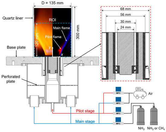
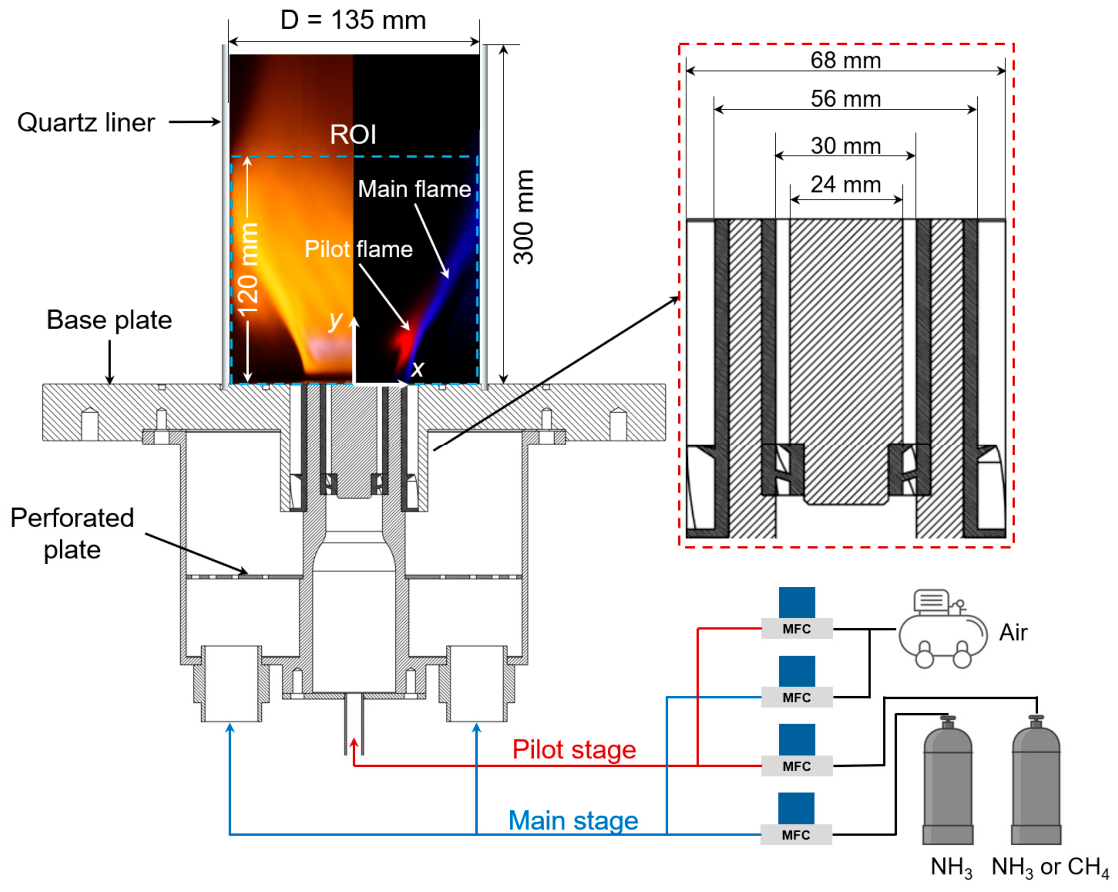
Figure 1 shows the schematic of the dual-swirl gas turbine model combustor, along with key dimensions. The model combustor features two coaxial counter-rotating swirlers, the pilot-stage one with a vane angle of 45° and the main-stage one with a vane angle of 30°. Swirl numbers (Sn) are calculated based on vane angle and the inner and outer diameter of the swirlers (Sn = ) [21]. The swirl numbers of the pilot and main stages are 0.9 and 0.53, respectively. The dual-swirl nozzle configuration features two stages. The inlet diameters of the two stages are shown in Figure 1. The premixed pilot fuel/air is injected solely into the pilot stage to establish a pilot flame, whilst ammonia is burned in the main stage. The confinement ratio of the main stage is ~2. The pilot flame operates in low-power mode but serves as an ignition source and thermal stabiliser for the main flame. The main flame is a premixed NH3/air flame, whilst the pilot flame is either a premixed NH3/air flame (APF) or a premixed CH4/air flame (MPF). Fuel and air are premixed in a mixing chamber before entering the combustor. The air flow rates in the two stages are independently controlled by two mass flow controllers (ALICAT MC series, ±1% accuracy), while the fuel flow rates are controlled by two other mass flow controllers (SevenStar D07-9E, ±2% accuracy). A quartz tube is used as the combustor wall for optical measurement.
Figure 1.
Schematic of the gas turbine model combustor.
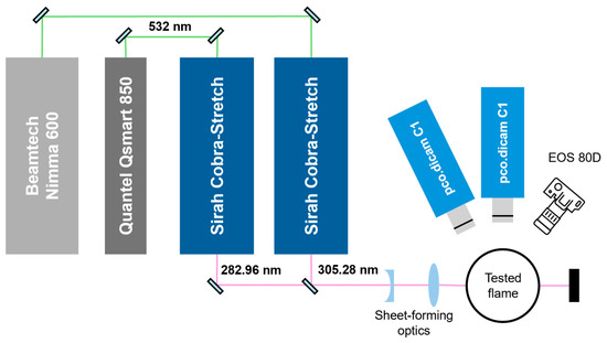
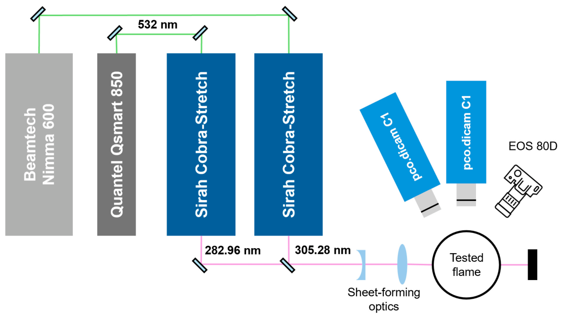
Figure 2 presents the flame diagnostic system. A Canon camera (EOS 80D) records the time-averaged flame images. The ISO, aperture, and exposure time are respectively 200, f/11, and 0.5 s. The laser system repetition rate is 10 Hz. The Nd:YAG laser sources (Q-smart 850, Quantel and Nimma 600, Beamtech) generate the raw laser beams with a wavelength of 532 nm. Then, the frequency is doubled with tuneable dye lasers (Cobra-Stretch, Sirah Lasertechnik) and the wavelength of the laser is transferred by each dye laser, respectively, to 282.9625 nm and 305.2798 nm. The average pulse energy of the 282.9625 nm laser is 13 mJ. It excites the Q1(8) line of A2Σ+–X2Π (0-0) transition of OH radical [22]. Meanwhile, the 305.2798 nm laser has an average pulse energy of 7.5 mJ. It activates the single-photon excitation of NH A3Π–X3Σ (1, 0) transition [23]. The laser beam is reshaped to obtain a laser sheet (120 mm in height and 0.5 mm in thickness) by a cylindrical concave plane lens and a spherical convex plane lens. The planar laser-induced fluorescence (PLIF) signals of OH and NH are simultaneously acquired with two intensified sCMOS cameras (pco.dicam C1), which provide a spatial resolution of ~11 pixel/mm. For OH measurement, a 310 nm bandpass filter (Edmund Optics, Barrington, NJ, USA, 310 ± 5 nm) is equipped. For NH measurement, a 340 nm bandpass filter (Edmund Optics, 340 ± 26 nm) is adopted. The PLIF images are calibrated with a calibration board (204-15, LaVision, Göttingen, Germany) to eliminate the distortion and justify the dimensions. The key experimental instruments in this work are listed in Table 1.
Figure 2.
Schematic of the OH and NH-PLIF diagnostic system.
Table 1.
Experimental instruments and key parameters.
The time phases of the lasers and cameras are synchronised by an analogue output device (NI PCIe-6738, Ha Noi City, Vietnam). It has a maximum update rate of 1 MS/s and produces a pulse signal with a time resolution of 1 ns. The signal output of the device is controlled by a LabVIEW programme, which can set the time delay between channels.
Experiments are conducted under atmospheric conditions. Table 2 lists the detailed experimental conditions. Across all tested conditions, the bulk velocity at the exit of the main-stage swirler is 2.3 m/s, and that at the exit of the pilot-stage swirler is 2.1 m/s. This corresponds to a pilot-stage Reynolds number of 1000 and a main-stage Reynolds number of 2800. Based on the empirical equation, TI = 0.153Re−0.0779, proposed by Russo et al. [24]. The turbulence intensities of the pilot stage and main stages are 8.9% and 8.2%, respectively. For stable flames, the effect of the pilot flame on main flame stability is examined by progressively increasing the thermal power of the pilot flame (Ppilot) whilst maintaining the thermal power of the main flame (Pmain). Thus, the equivalence ratio of the pilot flame (ϕpilot) varies while that of the main stage (ϕmain) is fixed at 1.0. For flame stability measurement, the ϕmain is decreased while keeping ϕpilot constant. The ϕmain at which a complete flame extinction occurs is defined as the main flame stability limit (ϕb,main). It is measured by decreasing the outer stage fuel flow rate whilst keeping the inner stage unchanged. The outer stage fuel flow rate corresponding to complete extinction of flames in the combustor is used to calculate ϕb,main. The ϕb,main is repeated three times to ensure repeatability. The structures of the flames approaching ϕb,main (ϕmain = ϕb,main + 0.02) are measured via PLIF.
Table 2.
Experimental conditions.
2.2. Data Postprocessing and Analysis Methods
The captured PLIF images are calibrated with the DaVis 8.0 program (LaVision). The NH-PLIF image resolution is 11.7015 pixel/mm, while the OH-PLIF image resolution is 10.8952 pixel/mm. The calibrated .im7 files are imported to MATLAB R2024b software to process simultaneously acquired OH-PLIF and NH-PLIF images to generate composite visualisations of radical distributions in the tested flames. For each pair of images, the NH-PLIF frame is first scaled to match the resolution of the OH-PLIF image using the ratio of the calibrated resolutions. Both images are then median-filtered to reduce noise and cropped to a common region of interest (0–60 mm in x, 0–120 mm in y), where x is the radial position of the combustor and y is the axial position, as illustrated in Figure 1. The OH signal is assigned to the red channel and the NH signal to the blue channel of an RGB image; each channel is normalised by its maximum intensity, and low-intensity pixels (<0.01 after normalisation) are set to zero to suppress background noise. A total of 300 PLIF images of OH and NH are used to obtain the time-averaged distribution. The resulting overlay is displayed and saved as a PNG file for analysis of the flame structure and the spatial correlation between OH and NH radicals.
Under the assumption of rotational symmetry for typical swirl flames, the total OH/NH signal intensity (IOH/INH) within the ROI is obtained by integrating the intensity over the radial direction with a weighting factor of where x is the radial coordinate (Equation (1)). The OH/NH density (ρOH/ρNH) is then defined as the ratio of the total integrated intensity to the volume of the flame region, where the volume is calculated from the binarized flame mask (threshold = 0.1).
NH-PLIF visualises the flame front of NH3 flames [25], and the flame surface density (FSD) of the NH3 main flame is calculated based on two-dimensional NH-PLIF results. The FSD is defined as [26]
where is the time-averaged surface area of flamelets within a cubic interrogation box of size . In this work, only two-dimensional information is available from NH-PLIF results. Thus, an approximation is made [27]:
where is the time-averaged length of flamelets within the control area of size .
For each image, the flame front is first identified using a custom function. In this function, each image is first median-filtered to reduce noise, converted to greyscale, and low-intensity background pixels (<0.2) are set to zero. Otsu’s method [28] is then applied to determine a binarization threshold, and the resulting binary image is cleaned by removing objects smaller than a specified number of pixels. For each row (i.e., each y-position), the code locates the transitions from unburned (0) to burnt (1) and vice versa, thereby identifying individual flame segments. For each such segment, the column index at the midpoint of the segment is recorded, and a binary matrix “flame_front” is generated with ones at these midline positions. This yields a thin, continuous representation of the flame front.
After extracting the flame front for all images, a 7 × 7 pixel sliding window is then applied to count the number of flame front pixels within each local neighbourhood. This count is then divided by the physical area of the window (derived from the imaging resolution of 11.7015 pixels/mm) to obtain the local FSD. The procedure is parallelised using a “parfor” loop for efficient batch processing. After processing all images, the ensemble-averaged FSD field is saved in a Tecplot-compatible data file, containing the spatial coordinates (x, y) and the corresponding FSD values. The FSD contours are generated with Tecplot 9.0 software.
3. Results and Discussions
3.1. Stable Flame Morphologies
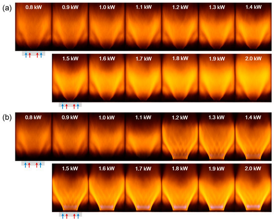
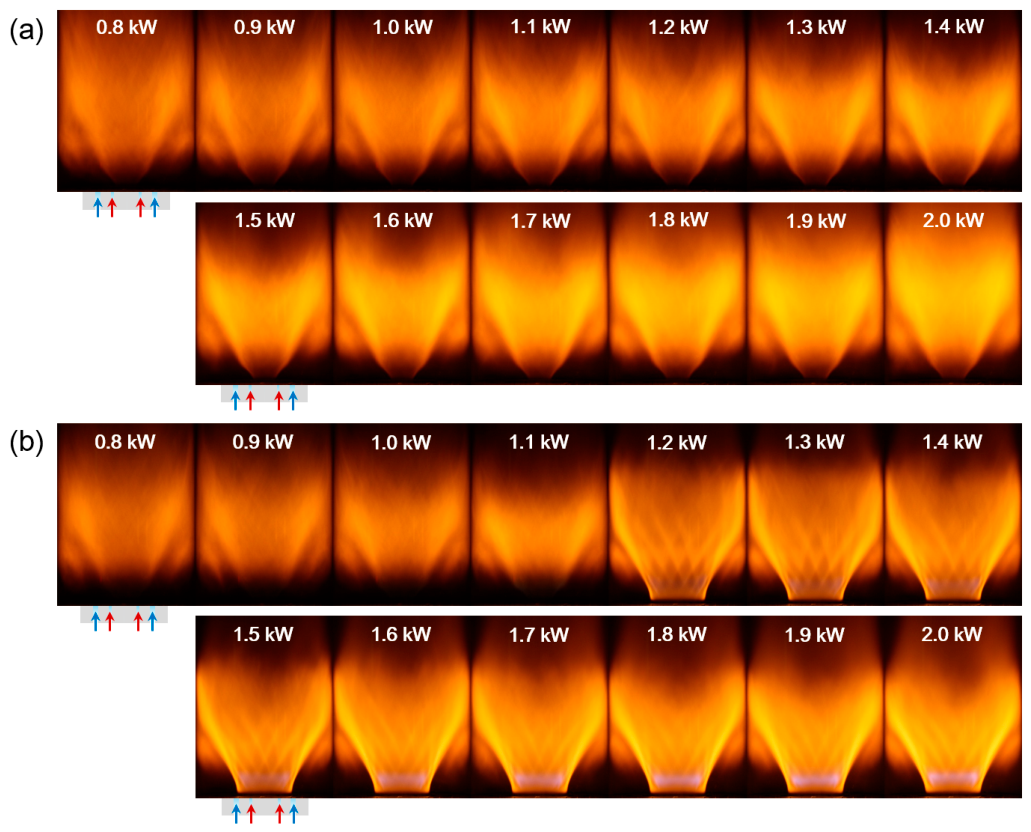
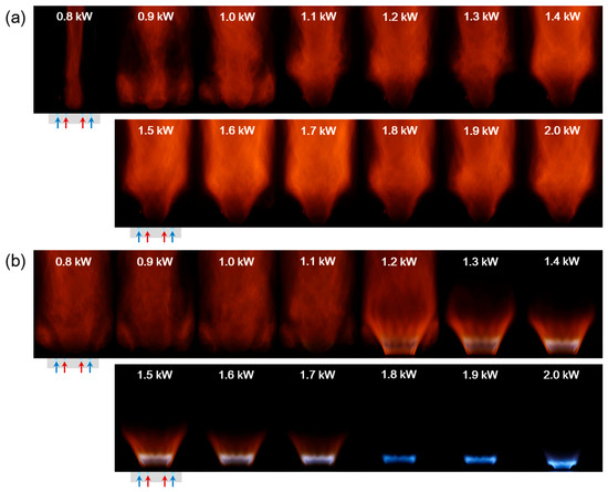
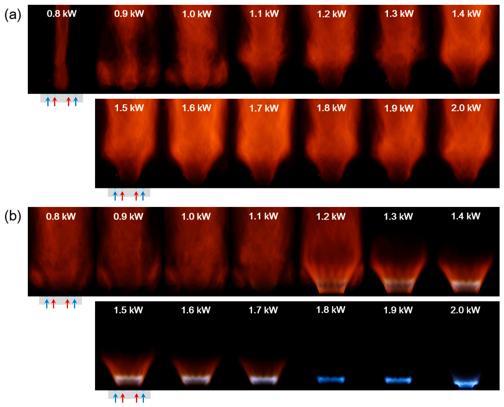
The pilot fuel type and thermal power have a large impact on the flame macrostructure of stable ammonia swirl flames. Figure 3 presents the time-averaged flame images of stoichiometric ammonia swirl flames with either APF or MPF. When NH3 is used as the pilot fuel, the flame chemiluminescence increases with increasing Ppilot. This can be attributed to elevated total thermal power and increased ammonia content. The former brings more heat to the combustor while maintaining a constant air flow rate, and the latter produces more NH2 radicals. Both factors enhance NH2* chemiluminescence from the A2A1 state of NH2 [29,30], resulting in a brighter ammonia flame. Despite the enhanced chemiluminescence, the flame macrostructure remains almost unchanged. Across all Ppilot values, the flame anchors exclusively at the pilot-stage exit, which can be attributed to the insufficient combustion reactivity of the APF and the dominance of the primary recirculation zone in flame stabilisation.
Figure 3.
Time-averaged flame image of stoichiometric ammonia swirl flames with (a) APF and (b) MPF at varying Ppilot (The red arrows indicate the pilot-stage mixture whilst the blue arrows indicate the main-stage mixture).
In contrast, ammonia main flames with MPF exhibit distinct flame chemiluminescence and macrostructures as Ppilot varies. At Ppilot = 0.8–1.1 kW, the flames appear to detach from the combustor base. However, a methane flame does exist in the dark area near the combustor base, although its CH* and C2* chemiluminescence [29] are too weak to be detected due to the low methane content. OH-PLIF results confirm the presence of this flame, as discussed later. Increasing Ppilot to 1.2 kW results in a stratified flame structure comprising the methane pilot flame and the ammonia main flame. At Ppilot = 1.2–2.0 kW, the chemiluminescence of the methane pilot flame grows progressively. In contrast to the blurred flame edges observed under other conditions, flames under these conditions exhibit sharp boundaries, indicating a stable main ammonia flame. Owing to the significantly higher combustion reactivity of methane than ammonia [31], methane/air mixtures can sustain an independent pilot flame at the pilot-stage exit. Despite operating at low power, this pilot flame acts as an ignition source and thermal stabiliser for the main flame, enabling it to anchor at the main-stage exit and maintain a stable structure.
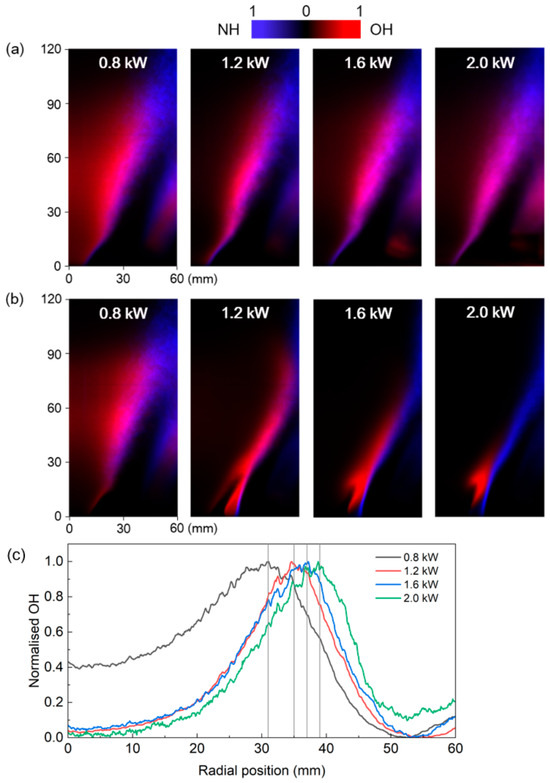
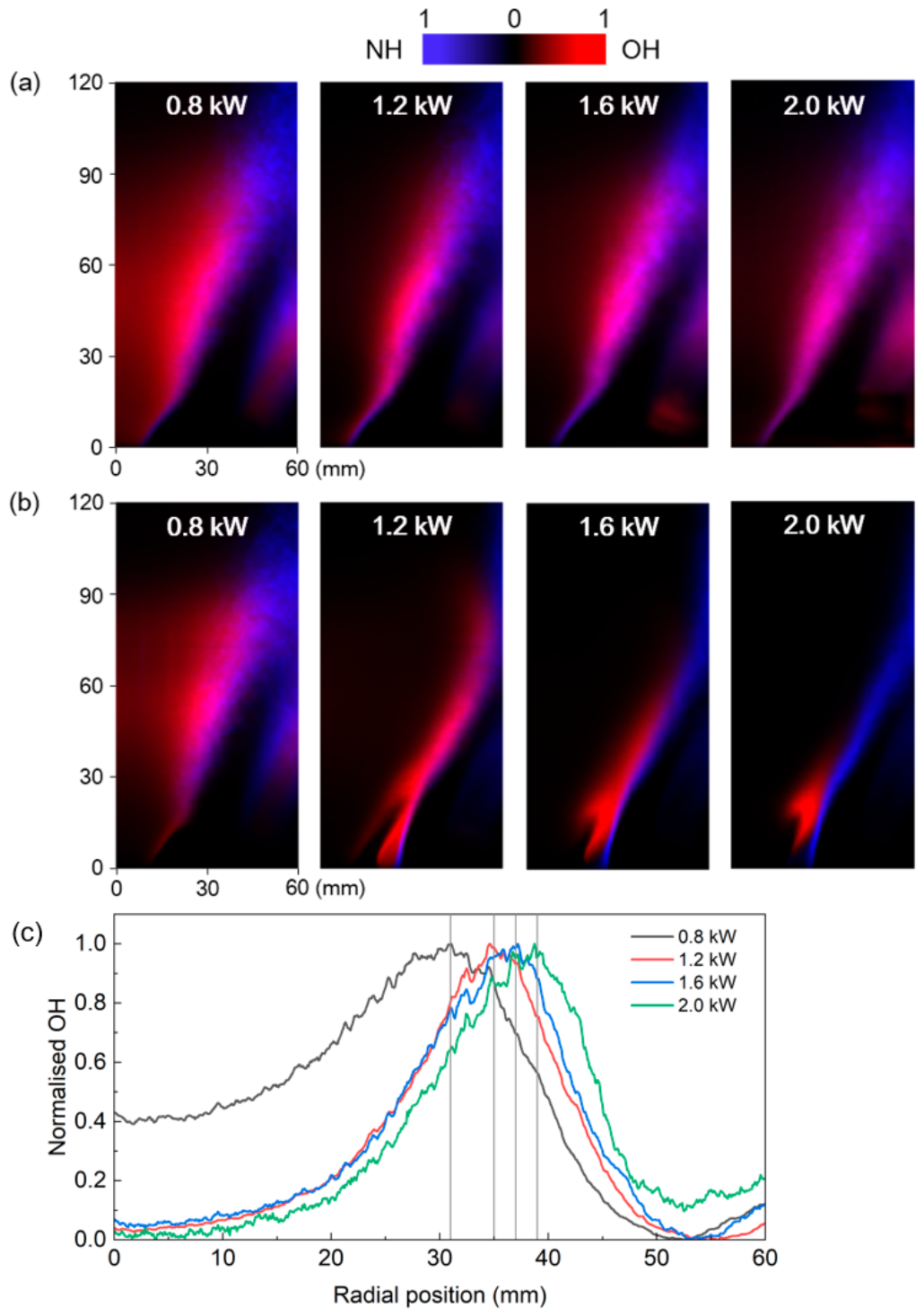
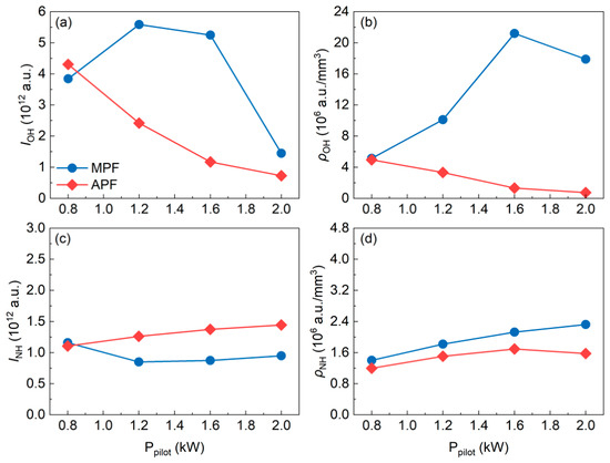
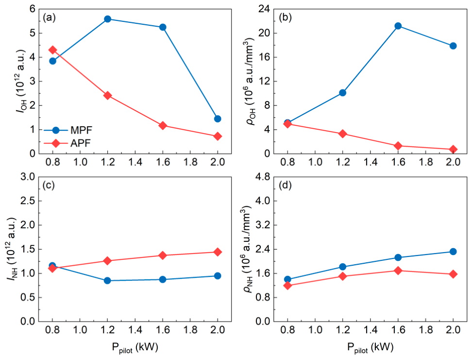
Detailed analysis of OH and NH distributions provides further insight into how the pilot flame influences the flame macrostructure. Figure 4 presents the normalised PLIF images of selected flames in Figure 3. Since the time-averaged PLIF images are symmetric, only the right halves of the images are shown for clarity. Figure 5 shows the total OH/NH PLIF signal intensities (denoted IOH and INH) and their corresponding signal densities (ρOH and ρNH).
Figure 4.
Normalised time-averaged NH/OH distribution of stoichiometric ammonia swirl flames with (a) APF and (b) MPF at varying Ppilot, along with (c) normalised radial profile of NH distribution at 60 mm above the combustor base in ammonia swirl flames with APF. Each image is normalised with its own maximum NH/OH signal intensity and thus only reflects the distribution of species. Each line in (c) is normalised with the radial maximum value.
Figure 5.
Total signal intensity of (a) OH and (c) NH at various Ppilot, together with their corresponding (b) OH and (d) NH signal density.
The normalised distribution of OH/NH radicals within ammonia swirl flames with APF and MPF are compared in Figure 4. For ammonia swirl flames with an APF, increasing Ppilot results in a more distributed OH radical field located farther from the central axis (Figure 4a). Moreover, at higher Ppilot, OH radicals appear at larger radial positions (Figure 4c), indicating a spatial shift in the main reaction zone. Whilst for ammonia swirl flames with an MPF, the variation in Ppilot leads to a distinct distribution of OH and NH. At Ppilot = 0.8 kW, the OH/NH distribution resembles that observed with the NH3 pilot flame (Figure 4). The OH signal can be observed near the combustor base, confirming the presence of a methane flame in this region. In addition, the total signal intensities and the signal densities of both radicals are comparable between the two pilot flame types. However, at Ppilot = 1.2–2.0 kW, the flame transitions to a stratified flame structure, with OH concentrated in the pilot stage whilst NH in the main stage.
The OH/NH signal intensity values are quantitatively compared in Figure 5. In ammonia swirl flames with an APF, as shown in Figure 5a,b, both the total intensity and signal density of OH decrease with increasing Ppilot. This trend is attributed to the variation in total equivalence ratio (ϕtotal). As Ppilot rises from 0.8 kW to 2.0 kW, ϕtotal rises from 0.88 to 0.99 as more NH3 is introduced to the combustor at a constant air flow rate. In typical swirl flames, reactants are primarily consumed in the shear layer [32] before being recirculated into the primary and corner recirculation zones. Within the equivalence ratio (ϕ) range of 0.8–1.1, the laminar burning velocity of NH3/air mixtures increases with ϕ [33], thereby enhancing the flame. It should be noted that increasing the ϕ to a higher value can cause a quenching effect and excess NH3 emissions. The decrease in IOH with increasing ϕtotal is consistent with observations by Zhang et al. [34] and Wei et al. [8] for ammonia swirl flames across ϕ = 0.8–1.0. In contrast to the intense variation in OH fluorescence, NH fluorescence exhibits only minor changes with Ppilot. As Ppilot increases, the total NH signal intensity rises slightly (Figure 5c) owing to higher NH3 content. However, the signal density and spatial distribution of NH remain largely unchanged.
In ammonia swirl flames with an MPF, although the total OH signal intensity varies with Ppilot due to increased ϕtotal at higher Ppilot, the OH signal density is significantly improved (Figure 5b), indicating a strong and compact reaction zone within the pilot stage. This establishes the MPF as an effective ignition source, providing a high-temperature environment and abundant reactive radicals, both of which significantly enhance the ignition of the main ammonia flame. As shown in Figure 5c,d, although the total NH intensity of flames with an MPF is lower than that with an APF due to the reduced ammonia content available for NH production, the NH signal density is higher. This indicates a more compact and intense reaction zone in the ammonia flame when stabilised by an MPF.
3.2. Main Flame Stability
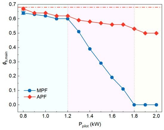
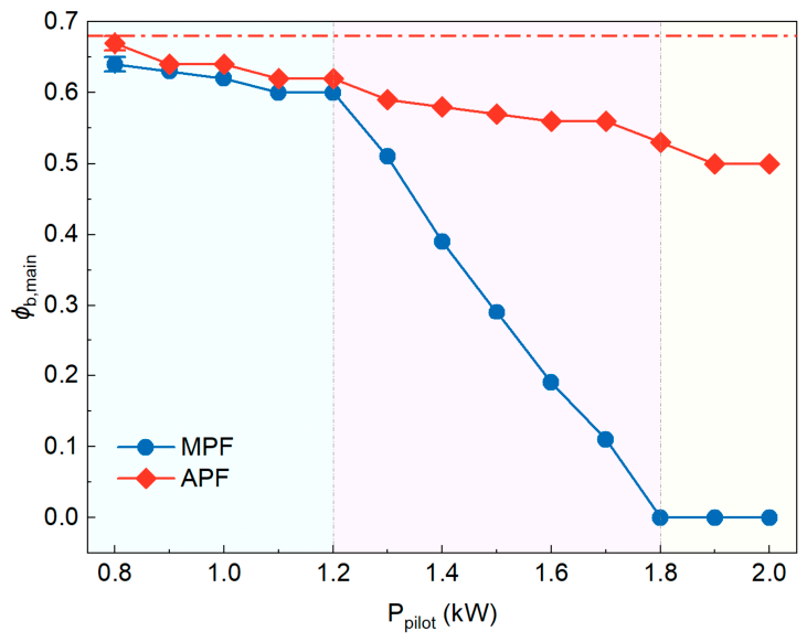
The variation in the type and power of the pilot flame leads to distinct stability limits of the flame, ϕb,main. As illustrated in Figure 6, with the increase in Ppilot, the flames with either CH4 or NH3 pilot flames exhibit higher stability compared to the single-stage ammonia main flame without pilot flames. Across all Ppilot values, flames stabilised with an MPF have a lower ϕb,main than those with an APF. For the APF, ϕb,main decreases almost linearly with Ppilot, demonstrating progressively enhanced flame stability. In contrast, the CH4-piloted flame displays a three-stage response. ϕb,main decreases slowly with Ppilot at low Ppilot values (the blue region in Figure 6), followed by a rapid decrease at intermediate Ppilot (the pink region in Figure 6). It should be noted that for Ppilot = 1.2–1.8 kW, Ppilot is only 14.2–21.3% of Pmain; such a low-power MPF can bring significantly improved flame stability to the main flame. At sufficiently high Ppilot, ϕb,main of the CH4-piloted flame reaches zero (the yellow region in Figure 6), indicating that the methane pilot flame can sustain stable combustion independently in the pilot stage without support from the main flame. By definition, ϕb,main refers to the main flame only, and it does not represent total system stability. However, the reactivity of ammonia is much lower than that of methane, so that the ammonia pilot flame cannot burn independently in the range of the current study.
Figure 6.
Measured ϕb,main of ammonia swirl flames with NH3 (red rhombuses) and CH4 (blue dots) pilot flames at different Ppilot. The dash-dot line marks the lean blow-off limit of the NH3 flame at the same total air flow rate but without pilot flames.
Corresponding to the variation in ϕb,main with Ppilot, flames approaching blow-off exhibit distinct behaviours. Figure 7 presents the time-averaged images of ammonia swirl flames approaching blow-off. For flames with an APF, and for those with an MPF at low Ppilot (<1.2 kW), the behaviour resembles that of atmospheric swirl flames approaching lean blow-off as reported by Skiba et al. [35]. In these cases, the ammonia flame mainly resides within the primary recirculation zone, which stabilises the flame by recirculating hot products back to the reactant mixture inlet [32]. For flames with an MPF at intermediate Ppilot (1.2–1.8 kW), a stratified structure develops, comprising a methane pilot flame and a main ammonia flame. The pilot flame supplies reactive radicals and a high-temperature environment to the main flame. Under these conditions, the main ammonia flame is stabilised predominantly by the pilot flame rather than by the primary recirculation zone. However, because the pilot flame is not yet strong enough to sustain itself independently in the pilot stage, blow-off still occurs when ϕmain is reduced to a critical threshold. At higher Ppilot (>1.7 kW), the equivalence ratio of the MPF exceeds 0.85, enabling the pilot flame to burn independently in the pilot stage. Therefore, even when the ϕmain is reduced to zero, the flame does not experience blow-off.
Figure 7.
Time-averaged flame images of ammonia swirl flames approaching blow-off (ϕ = ϕb,main + 0.02) with (a) APF and (b) MPF at varying Ppilot.
3.3. Enhancement of Pilot Flame on Main Flame Stability
To understand the mechanism behind the enhanced main flame stability, this work performs a detailed analysis of the stable flame and the flames approaching blow-off. The flame surface density (FSD) within the stable flames is calculated to quantitatively compare the combustion enhancement effects of APF and MPF. Moreover, the instantaneous distribution of OH/NH radicals within flames approaching blow-off is analysed to characterise the effect of the pilot flame on main flame stabilisation.
FSD is an important parameter in analysing turbulent flames. In turbulent premixed combustion, the mean reaction rate can be expressed as [36]
where is the unburned gas density, is the stretched laminar burning velocity, and is the FSD. Moreover, the turbulent burning velocity () and flame wrinkling ratio () is also correlated with FSD [26]:
where is the coordinate normal to the flame brush. According to Pope [37] and Halter et al. [38], the local FSD is determined as
where is the progress variable, describing the reaction progress, with 0 corresponding to the fresh mixture and one the burnt mixture. represents the conditional average modulus of progress variable gradient for . is the probability of at the specific location.
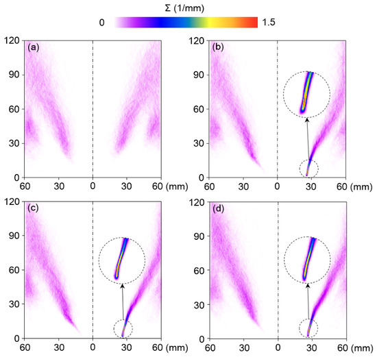
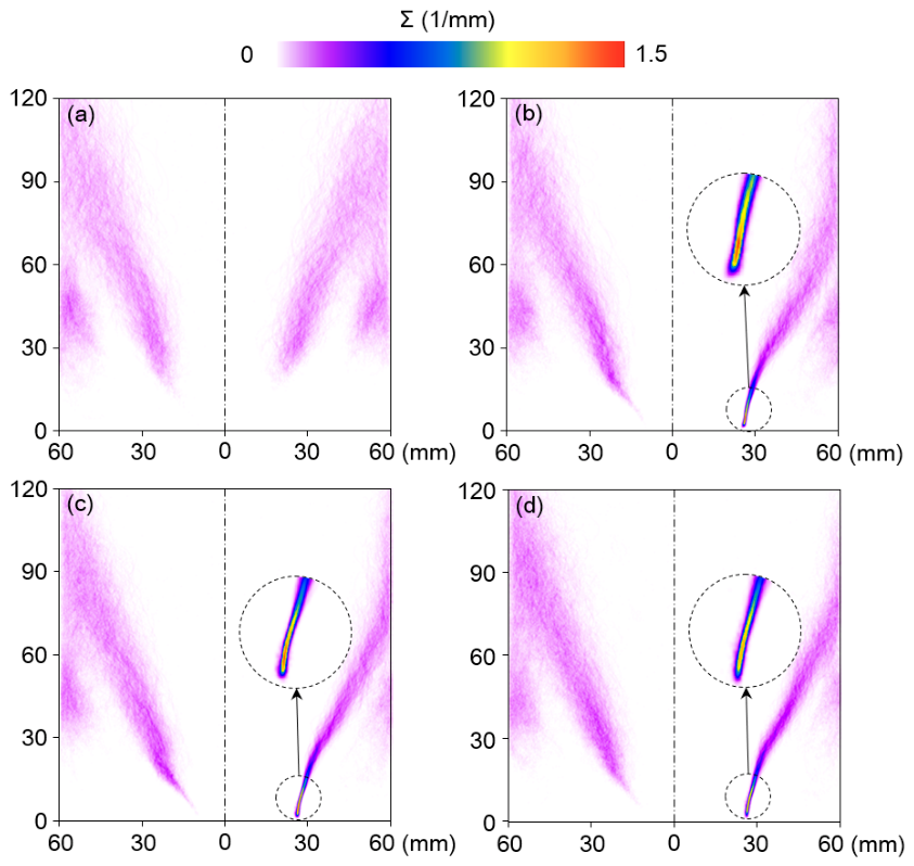
Since the present study focuses on the flame stability of the main flame, NH, rather than OH, is used to indicate the flame front and define the flame brush. Compared with the APF, the MPF demonstrates superior performance in enhancing ammonia flame surface density, particularly at the flame root. Figure 8 presents the FSD contours of ammonia swirl flames with different pilot flames and at various Ppilot values. At Ppilot = 0.8 kW, flames with either pilot flame exhibit low FSD and a thick flame brush, indicating that the ammonia flame is highly vulnerable to perturbation under these conditions [39]. At higher Ppilot, flames stabilised by the MPF exhibit markedly elevated FSD at the flame root. As illustrated in Equation (6), elevated FSD reflects a higher probability of flame front in this region, which means a stable flame root is formed. Therefore, the MPF establishes a stable flame front at the root of the main ammonia flame. In contrast, although higher FSD is also observed at flame root in NH3-piloted flames at Ppilot = 1.2–2.0 kW, the enhancement remains relatively limited.
Figure 8.
Flame surface density contour of ammonia swirl flames with APF (left) and MPF (right) at Ppilot = (a) 0.8 kW, (b) 1.2 kW, (c) 1.6 kW, and (d) 2.0 kW.
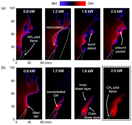
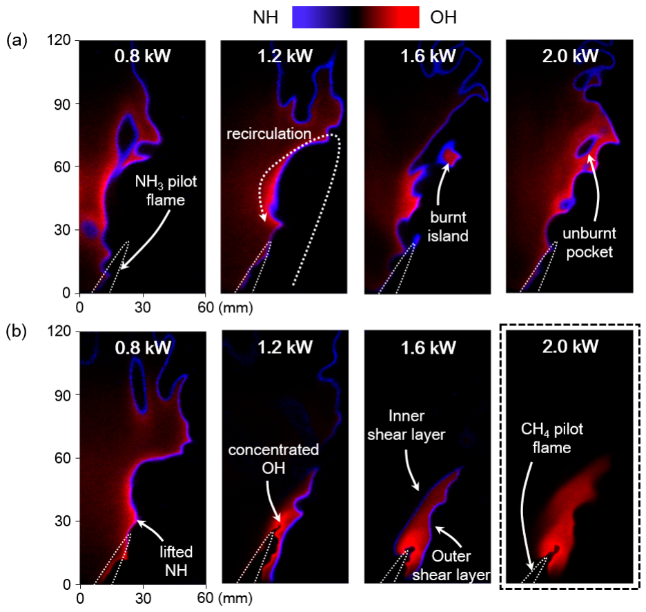
The above-mentioned variations in ϕb,main and flame structures can be attributed to different flame stabilisation modes as the flame approaches blow-off. Figure 9 presents instantaneous NH/OH distributions in ammonia swirl flames approaching blow-off. For flames with an APF, burnt islands and unburnt pockets are observed, which is attributed to turbulence–flame interactions [40]. This indicates that the flame experiences local extinction under these conditions [32]. Under these conditions, the APF forms a V-shape flame at the pilot-stage exit, with the combustion region located in the inner shear layer. The main flame reactants are recirculated to the primary recirculation zone before being ignited, and the flame is mainly stabilised by the primary recirculation zone.
Figure 9.
Instantaneous normalised NH/OH distribution in ammonia swirl flames approaching blow-off with (a) APF and (b) MPF at varying Ppilot.
In contrast, the MPF results in distinct flame characteristics under approaching blow-off conditions. At Ppilot = 0.8 kW, strong OH signals can be observed at the flame root, while NH is located further downstream, resulting in a lifted NH region. Similar to the APF, a V-shape CH4 flame anchors at the pilot-stage exit and the main flame is ignited in the inner shear layer. This suggests that ammonia swirl flames with a low-power MPF are also stabilised by the primary recirculation zone. At higher Ppilot, however, a robust M-shape CH4 flame is established at the pilot stage, with OH distributed in both the inner and outer shear layers of the pilot stage. The transition of the pilot flame from V-shape to M-shape can be attributed to its increased resistance to strain, which allows the flame to propagate and stabilise in the highly strained outer shear layer region [41]. This forms a stable ignition source for the main flame at the main-stage exit and in the primary recirculation zone, enabling efficient NH3 consumption and NH formation in these two regions. As Ppilot is further increased to 2.0 kW, the pilot flame can burn independently at the pilot stage while no ammonia is supplied to the main stage, and the figure enclosed by the dashed box in Figure 9 is the OH-PLIF from a pure methane flame.
To conclude, two flame stabilisation mechanisms within ammonia swirl flames can be revealed. For flames with APFs and MPFs of low Ppilot, the flame is mainly stabilised by the primary recirculation zone, where pilot flames provide an ignition source. In contrast, for flames with MPFs of high Ppilot, the M-shape pilot flame provides an ignition source at the main-stage exit and in the primary recirculation zone, which is more effective in stabilising the main flame. At a Ppilot that is 14.2–21.3% of Pmain, the main flame stability is significantly enhanced. Compared to a methane flame of an identical thermal power, this approach is estimated to reduce carbon emissions by 82.4–87.6%. At Ppilot = 1.8 kW, the thermal power of the pilot flame only counts for 21.3% of the main flame under stable operating conditions. However, the pilot flame guarantees the flame against blow-off even if no fuel is supplied to the main stage.
4. Conclusions
This study investigates the flame morphologies, flame surface density, and stability limits of premixed ammonia/air main flames stabilised by a pilot flame in a dual-swirl gas turbine model combustor. The effects of pilot fuel type (NH3 vs. CH4) and thermal power are systematically examined. The main conclusions are as follows:
- For flames with APF, increasing Ppilot shifts the OH radicals radially outward and reduces both total OH intensity and density, while NH distribution remains largely unchanged. For flames with MPF, a stratified structure emerges at Ppilot ≥ 1.2 kW, with OH concentrated in the pilot stage and NH in the main stage. Although the total NH intensity is lower for flames with MPF, the NH signal density is significantly higher, indicating a more compact and intense reaction zone in the main ammonia flame.
- Flames with MPF exhibit lower ϕb,main than those with APF across all Ppilot values. The MPF markedly enhances the FSD of the ammonia main flame, particularly at the flame root, where elevated FSD reflects a higher probability of flame front occurrence. At Ppilot = 1.2–2.0 kW, flames stabilised by MPF exhibit narrower radial FSD profiles and higher peak values compared to those with APF, indicating a thinner flame brush and improved flame stability. The effective flame stabilisation results from the abundance of reactive radicals and the high-temperature environment provided to the main flame root.
- Two stabilisation modes are identified for ammonia main flames as Ppilot increases, namely primary recirculation zone-dominated stabilisation with APF and with MPF at low Ppilot (<1.2 kW) and pilot-dominated stabilisation with MPF at intermediate Ppilot (1.2–1.8 kW), where the main flame is sustained by the ignition source formed by the pilot flame at the main-stage exit and in the primary recirculation zone. Compared to a methane flame of an identical thermal power, an MPF at Ppilot = 1.2–1.8 kW can reduce carbon emissions by 82.4–87.6%. These findings demonstrate that a low-power MPF offers an effective strategy for enhancing ammonia flame stability in gas turbine combustors and reducing carbon emissions.
Author Contributions
Conceptualization, T.L., Y.Z. and Y.L.; methodology, S.B.; formal analysis and data curation, T.L., Y.Z., S.C. and X.S.; investigation, T.L., Y.Z., S.B., S.C. and J.J.; writing—original draft preparation, T.L. and X.S.; writing—review and editing, X.S. and Y.L.; supervision, X.S. and Y.L. All authors have read and agreed to the published version of the manuscript.
Funding
This work is funded by the Explorers Program of Shanghai (Basic Research Funding) under Grant Number 25TS1414400 and the National Natural Science Foundation of China (52506157, 52525605). X.S. acknowledges the financial support from the China Postdoctoral Science Foundation (2025T180165, 2024M761968) and the Postdoctoral Fellowship Program of CPSF (GZC20250415).
Data Availability Statement
The raw data supporting the conclusions of this article will be made available by the authors on request.
Conflicts of Interest
The authors declare no conflicts of interest.
Nomenclature
| APF | Ammonia pilot flame |
| MPF | Methane pilot flame |
| PLIF | Planar laser-induced fluorescence |
| LBO | Lean blow-off |
| Ppilot | Pilot flame thermal power |
| Pmain | Main flame thermal power |
| ϕpilot | Pilot flame equivalence ratio |
| ϕmain | Main flame equivalence ratio |
| ϕb,main | Main flame stability limit |
| Sn | Swirl number |
References
- Li, Y.; Lian, T.; Liu, Z.; Zhang, Y.; Shi, X.; Li, W. Ammonia combustion for gas turbine decarbonation: Opportunities, strategies, and challenges. Proc. Combust. Inst. 2025, 41, 105876. [Google Scholar] [CrossRef] [Scilit]
- Zhang, M.; Wei, X.; An, Z.; Okafor, E.C.; Guiberti, T.F.; Wang, J.; Huang, Z. Flame stabilization and emission characteristics of ammonia combustion in lab-scale gas turbine combustors: Recent progress and prospects. Prog. Energy Combust. Sci. 2025, 106, 101193. [Google Scholar] [CrossRef] [Scilit]
- Tian, X.; Liu, S.; Fang, J.; Zhang, Q.; Feng, Z.; Fang, Q. Experimental and kinetic modeling investigation on ignition characteristics of hydrogen: Effects of methane co-firing and dilution gas. Prog. React. Kinet. Mech. 2024, 49, e003. [Google Scholar] [CrossRef] [Scilit]
- Gaucherand, J.; Laera, D.; Schulze-Netzer, C.; Poinsot, T. Intrinsic instabilities of hydrogen and hydrogen/ammonia premixed flames: Influence of equivalence ratio, fuel composition and pressure. Combust. Flame 2023, 256, 112986. [Google Scholar] [CrossRef] [Scilit]
- MAN B&W Two-Stroke Engine Operating on Ammonia; MAN Energy Solutions: Copenhagen, Denmark, 2023.
- Ishihara, S.; Zhang, J.; Ito, T. Numerical calculation with detailed chemistry of effect of ammonia co-firing on NO emissions in a coal-fired boiler. Fuel 2020, 266, 116924. [Google Scholar] [CrossRef] [Scilit]
- Niu, T.; Zhang, W.; Liu, X.; Hu, D.; Wang, T.; Xie, Y.; Wang, H. Industrial-scale experimental investigation of ammonia-coal cofiring in coal-fired boiler. Clean Coal Technol. 2022, 28, 193–200. [Google Scholar] [CrossRef]
- Wei, X.; Zhang, M.; Wang, J.; Huang, Z. Investigation on lean blow-off characteristics and stabilization mechanism of premixed hydrogen enhanced ammonia/air swirl flames in a gas turbine combustor. Combust. Flame 2023, 249, 112600. [Google Scholar] [CrossRef] [Scilit]
- Somarathne, K.D.K.A.; Okafor, E.C.; Sugawara, D.; Hayakawa, A.; Kobayashi, H. Effects of OH concentration and temperature on NO emission characteristics of turbulent non-premixed CH4/NH3/air flames in a two-stage gas turbine like combustor at high pressure. Proc. Combust. Inst. 2021, 38, 5163–5170. [Google Scholar] [CrossRef] [Scilit]
- Ji, L.; Wang, J.; Hu, G.; Mao, R.; Zhang, W.; Huang, Z. Experimental study on structure and blow-off characteristics of NH3/CH4 co-firing flames in a swirl combustor. Fuel 2022, 314, 123027. [Google Scholar] [CrossRef] [Scilit]
- Lian, T.; Shi, X.; Han, S.; Zhang, Y.; Liu, Z.; Xi, Z.; Li, W.; Li, Y. Unraveling the impact of CO2 exhaust gas recirculation on flame characteristics and NOx emissions of premixed NH3/DME swirl flames. Appl. Energy Combust. Sci. 2024, 17, 100256. [Google Scholar] [CrossRef] [Scilit]
- Liu, Z.; Bin, S.; Chen, S.; Jiang, J.; Zhang, Y.; Shi, X.; Li, W.; Zhang, H.; Li, Y. Insights into combustion and emission characteristics of ammonia co-firing with hydrogen-rich gas for gas turbine applications. Energy 2025, 324, 135967. [Google Scholar] [CrossRef] [Scilit]
- Okafor, E.C.; Somarathne, K.D.K.A.; Ratthanan, R.; Hayakawa, A.; Kudo, T.; Kurata, O.; Iki, N.; Tsujimura, T.; Furutani, H.; Kobayashi, H. Control of NOx and other emissions in micro gas turbine combustors fuelled with mixtures of methane and ammonia. Combust. Flame 2020, 211, 406–416. [Google Scholar] [CrossRef] [Scilit]
- Linstrom, P.J.; Mallard, W.G. (Eds.) NIST Chemistry WebBook; NIST Standard Reference Database Number 69; National Institute of Standards and Technology: Gaithersburg MD, USA, 2025. [Google Scholar] [CrossRef] [Scilit]
- Ateshkadi, A.; McDonell, V.G.; Samuelsen, G.S. Effect of hardware geometry on gas and drop behavior in a radial mixer spray. Symp. Int. Combust. 1998, 27, 1985–1992. [Google Scholar] [CrossRef] [Scilit]
- Soliman, K.M.; Mater, E.O.; Moneib, H.A.; Abdulnaim, A.M. Optimization of thermal and combustion performance for diesel-LPG cofiring in a novel double swirl burner. Fuel 2026, 404, 136258. [Google Scholar] [CrossRef] [Scilit]
- Foust, M.J.; Thomsen, D.; Stickles, R.; Cooper, C.; Dodds, W. Development of the GE aviation low emissions TAPS combustor for next generation aircraft engines. In Proceedings of the 50th AIAA Aerospace Sciences Meeting Including the New Horizons Forum and Aerospace Exposition, Nashville, TN, USA, 9–12 January 2012; p. 0936. [Google Scholar] [CrossRef] [Scilit]
- Elbaz, A.M.; Albalawi, A.M.; Wang, S.; Roberts, W.L. Stability and characteristics of NH3/CH4/air flames in a combustor fired by a double swirl stabilized burner. Proc. Combust. Inst. 2023, 39, 4205–4213. [Google Scholar] [CrossRef] [Scilit]
- Elbaz, A.M.; Hassan, Z.O.; Albalawi, A.M.; Ahmed, M.M.A.; Abdullah, M.; Cenker, E.; Roberts, W.L. Investigating NO emissions, stability, and flame structure in co-fired premixed NH3/CH4/air swirling flames. Combust. Flame 2025, 272, 113892. [Google Scholar] [CrossRef] [Scilit]
- Li, Y.; Sun, J.; Huang, Q.; Kneer, R.; Li, S. Effects of fuel/air distribution on the NH3/CH4 flame stability limit and NOx emission in a dual-annular burner. Combust. Flame 2024, 268, 113606. [Google Scholar] [CrossRef] [Scilit]
- Vignat, G.; Durox, D.; Candel, S. The suitability of different swirl number definitions for describing swirl flows: Accurate, common and (over-) simplified formulations. Prog. Energy Combust. Sci. 2022, 89, 100969. [Google Scholar] [CrossRef] [Scilit]
- Dyer, M.J.; Crosley, D.R. Two-dimensional imaging of OH laser-induced fluorescence in a flame. Opt. Lett. 1982, 7, 382–384. [Google Scholar] [CrossRef] [Scilit]
- Rensberger, K.J.; Copeland, R.A.; Wise, M.L.; Crosley, D.R. NH and CH laser-induced fluorescence in low-pressure flames: Quantum yields from time-resolved measurements. Symp. Int. Combust. 1989, 22, 1867–1875. [Google Scholar] [CrossRef] [Scilit]
- Russo, F.; Basse, N.T. Scaling of turbulence intensity for low-speed flow in smooth pipes. Flow Meas. Instrum. 2016, 52, 101–114. [Google Scholar] [CrossRef] [Scilit]
- Fan, Q.; Liu, X.; Cai, X.; Brackmann, C.; Alden, M.; Bai, X.-S.; Li, Z. Structure and scalar correlation of ammonia/air turbulent premixed flames in the distributed reaction zone regime. Combust. Flame 2022, 241, 112090. [Google Scholar] [CrossRef] [Scilit]
- Driscoll, J.F. Turbulent premixed combustion: Flamelet structure and its effect on turbulent burning velocities. Prog. Energy Combust. Sci. 2008, 34, 91–134. [Google Scholar] [CrossRef] [Scilit]
- Zhang, M.; Wang, J.; Xie, Y.; Wei, Z.; Jin, W.; Huang, Z.; Kobayashi, H. Measurement on instantaneous flame front structure of turbulent premixed CH4/H2/air flames. Exp. Therm. Fluid Sci. 2014, 52, 288–296. [Google Scholar] [CrossRef] [Scilit]
- Otsu, N. A threshold selection method from gray-level histograms. IEEE Trans. Syst. Man Cybern. 1979, 9, 62–66. [Google Scholar] [CrossRef] [Scilit]
- Konnov, A.A. An exploratory modelling study of chemiluminescence in ammonia-fuelled flames. Part 1. Combust. Flame 2023, 253, 112788. [Google Scholar] [CrossRef] [Scilit]
- Pugh, D.; Runyon, J.; Bowen, P.; Giles, A.; Valera-Medina, A.; Marsh, R.; Goktepe, B.; Hewlett, S. An investigation of ammonia primary flame combustor concepts for emissions reduction with OH*, NH2* and NH* chemiluminescence at elevated conditions. Proc. Combust. Inst. 2021, 38, 6451–6459. [Google Scholar] [CrossRef] [Scilit]
- Zhang, M.; Wei, X.; Wang, J.; Huang, Z.; Tan, H. The blow-off and transient characteristics of co-firing ammonia/methane fuels in a swirl combustor. Proc. Combust. Inst. 2021, 38, 5181–5190. [Google Scholar] [CrossRef] [Scilit]
- Shi, X.; Liu, Z.; Lian, T.; Han, S.; Zhang, Y.; Xi, Z.; Li, W.; Li, Y. Effects of wall confinement on flame topologies and lean blowout characteristics of partially premixed DME/air flames in a gas turbine model combustor. Fuel 2024, 372, 132232. [Google Scholar] [CrossRef] [Scilit]
- Okafor, E.C.; Naito, Y.; Colson, S.; Ichikawa, A.; Kudo, T.; Hayakawa, A.; Kobayashi, H. Experimental and numerical study of the laminar burning velocity of CH4–NH3–air premixed flames. Combust. Flame 2018, 187, 185–198. [Google Scholar] [CrossRef] [Scilit]
- Zhang, M.; An, Z.; Wang, L.; Wei, X.; Jianayihan, B.; Wang, J.; Huang, Z.; Tan, H. The regulation effect of methane and hydrogen on the emission characteristics of ammonia/air combustion in a model combustor. Int. J. Hydrogen Energy 2021, 46, 21013–21025. [Google Scholar] [CrossRef] [Scilit]
- Skiba, A.W.; Guiberti, T.F.; Boyette, W.R.; Roberts, W.L.; Mastorakos, E. On the bi-stable nature of turbulent premixed bluff-body stabilized flames at elevated pressure and near lean blow-off. Proc. Combust. Inst. 2021, 38, 2853–2860. [Google Scholar] [CrossRef] [Scilit]
- Lee, G.G.; Huh, K.Y.; Kobayashi, H. Measurement and analysis of flame surface density for turbulent premixed combustion on a nozzle-type burner. Combust. Flame 2000, 122, 43–57. [Google Scholar] [CrossRef] [Scilit]
- Pope, S.B. The evolution of surfaces in turbulence. Int. J. Eng. Sci. 1988, 26, 445–469. [Google Scholar] [CrossRef] [Scilit]
- Halter, F.; Chauveau, C.; Gökalp, I.; Veynante, D. Analysis of flame surface density measurements in turbulent premixed combustion. Combust. Flame 2009, 156, 657–664. [Google Scholar] [CrossRef] [Scilit]
- Zhang, W.; Wang, J.; Lin, W.; Guo, S.; Zhang, M.; Li, G.; Ye, J.; Huang, Z. Measurements on flame structure of bluff body and swirl stabilized premixed flames close to blow-off. Exp. Therm. Fluid Sci. 2019, 104, 15–25. [Google Scholar] [CrossRef] [Scilit]
- Tyagi, A.; Boxx, I.; Peluso, S.; O’Connor, J. Pocket formation and behavior in turbulent premixed flames. Combust. Flame 2020, 211, 312–324. [Google Scholar] [CrossRef] [Scilit]
- Guiberti, T.F.; Durox, D.; Scouflaire, P.; Schuller, T. Impact of heat loss and hydrogen enrichment on the shape of confined swirling flames. Proc. Combust. Inst. 2015, 35, 1385–1392. [Google Scholar] [CrossRef] [Scilit]

Disclaimer/Publisher’s Note: The statements, opinions and data contained in all publications are solely those of the individual author(s) and contributor(s) and not of MDPI and/or the editor(s). MDPI and/or the editor(s) disclaim responsibility for any injury to people or property resulting from any ideas, methods, instructions or products referred to in the content. |
© 2026 by the authors. Licensee MDPI, Basel, Switzerland. This article is an open access article distributed under the terms and conditions of the Creative Commons Attribution (CC BY) license.