Article

Experimental Investigation of Motion Control of a Closed-Kinematic Chain Robot Manipulator Using Synchronization Sliding Mode Method with Time Delay Estimation

1
Department of Electrical Engineering and Computer Science, School of Engineering, The Catholic University of America, 620 Michigan Ave NE, Washington, DC 20064, USA
2
Faculty of Electrical and Electronics Engineering, Ho Chi Minh City University of Technology and Education (HCMUTE), 01, Vo Van Ngan Street, Thu Duc City, Ho Chi Minh City 70000, Vietnam
*
Author to whom correspondence should be addressed.
Appl. Sci. 2025, 15(9), 5206; https://doi.org/10.3390/app15095206
Submission received: 30 March 2025 / Revised: 2 May 2025 / Accepted: 3 May 2025 / Published: 7 May 2025
(This article belongs to the Section Robotics and Automation)

Abstract

:
Closed-Kinematic Chain Manipulators (CKCM) have gained attention due to their precise Cartesian motion capability through coordinated active joint movements. Furthermore, ensuring synchronization among the joints of CKCMs is critical for reliable operation. An advanced control scheme for CKCMs that combines Nonsingular Fast Terminal Sliding Mode Control (NFTSMC) with Time Delay Estimation (TDE) while utilizing synchronization errors, namely Syn-TDE-NFTSMC, to effectively address joint errors in CKCMs was developed. NFTSMC enables fast convergence through nonlinear terminal sliding while TDE eliminates the need for prior knowledge of the robot’s dynamics, thereby simplifying its implementation and reducing its computational requirements. It is known that the inclusion of TDE reduces about 98% of the computational requirement of control schemes without TDE. The newly developed control scheme was rigorously evaluated using computer simulation and its control performance was compared with that of existing control methods. This paper presents an experimental study where the newly developed control scheme and other existing control schemes were applied to a real CKCM with 2 degrees of freedom (DOF). The experimental results confirm that the control scheme performed much better than other existing control schemes in terms of synchronization and control performance, achieving a reduction in maximum tracking errors of up to 81% as compared to other existing control schemes. The results confirm the efficacy of the newly developed control scheme in enhancing control precision and system stability, making it a promising solution for improving CKCM control strategies in real-world applications.

1. Introduction

Closed-Kinematic Chain Manipulators (CKCMs) have drawn significant attention in the robotics community due to their ability to achieve precise Cartesian motion through coordinated active joint movements. Compared to Open-Kinematic Chain Manipulators (OKCM), CKCMs offer improved positioning accuracy and payload handling capabilities [1,2,3,4]. However, CKCMs also present challenges, including limited workspace, absence of closed-form solutions for forward kinematics, and synchronization issues among joints and end-effectors. Since synchronization errors can degrade tracking accuracy and even damage the mechanical structure, especially under high accelerations or abrupt payload changes, various synchronization-based control schemes have been developed [5,6,7,8,9].
To implement effective control schemes in a real robot in real time, the control laws must have simple structures and should not rely on knowledge of the manipulator’s dynamics. As a result, synchronized adaptive and PD control schemes have been explored in [10,11,12] for this purpose. Additionally, a traditional sliding mode control (SMC) scheme developed by authors in [13,14] was employed to control the motion of CKCMs. SMC is advantageous due to its robustness against uncertainties and disturbances in system parameter variations, making it suitable for CKCMs [13,15,16,17]. However, the SMC approach applied to manipulators can only guarantee asymptotic stability, requiring finite time to converge to an equilibrium.
To achieve finite-time convergence, the terminal SMC (TSMC) scheme was developed in [18,19,20]. This approach includes a driving component that forces the system’s trajectory towards a stable sliding surface, which is designed to enforce the system’s desired error dynamics. However, TSMC has two main limitations: a slower convergence to equilibrium as compared to the traditional SMC when the system state is far from the equilibrium, and an issue in dealing with singularity [21,22]. To address these, an enhanced version called Nonsingular Fast Terminal Sliding Mode Control (NFTSMC) was introduced in [23,24], incorporating synchronization to control a parallel robot manipulator. This improved control scheme overcomes singularity and achieves fast convergence [25]. Despite its advantages, the gain selection in NFTSMC still depends on conservative estimates of the manipulator’s dynamic model, resulting in calculational challenges due to the highly complicated dynamic model of the manipulator. To overcome this issue, a model-free controller utilizing Time Delay Estimation (TDE) was developed. Over the past decade, TDE-based controllers have been widely used for robot manipulators due to their computation efficiency [26,27,28]. By using time-delayed information, TDE effectively estimates unknown dynamics and disturbances within a sufficiently small time delay, where the uncertainty can be considered as a continuous or piecewise continuous function. Thus, the approximation uncertainty is inherently satisfied [24]. In addition, TDE has been combined with Nonsingular Terminal Sliding Mode (NTSM) control [29] to deliver highly robust and precise control with fast, finite-time convergence.
A recent study [15] introduced Syn-TDE-NFTSMC for CKCMs, a TDE-based NFTSMC scheme with synchronization error handling. A simulation study indicated that this control scheme outperformed existing control schemes, including LINEAR, TDE-based LINEAR (TDE-LINEAR), TDE-based LINEAR with synchronization errors (Syn-TDE-LINEAR), and TDE-based SMC with synchronization errors (Syn-TDE-SMC), in controlling the CKCM motion. For instance, a comparison of the tracking errors showed that Syn-TDE-NFTSMC achieved a better performance, with the error of 4.07 × 10 3 mm for Joint 1 being notably smaller than those of the other control schemes—specifically, errors of 0.32 mm, 0.0197 mm, 0.0197 mm, and 7.17 × 10 3 mm were observed for LINEAR, TDE-LINEAR, Syn-TDE-LINEAR, and Syn-TDE-SMC, respectively. However, experimental validation of this approach has not been conducted. This paper focuses on the experimental aspect of the above control scheme and is organized as follows. Section 2 describes the main components of the real CKCM possessing 2 degrees of freedom (DOF) to be employed in our experimental study. Section 3 details the implementation of the newly developed Syn-TDE-NFTSMC scheme to control the motion of the above manipulator. The results of the experimental study are presented and discussed in Section 4. Section 5 concludes the paper with comments, key findings, and future research directions.

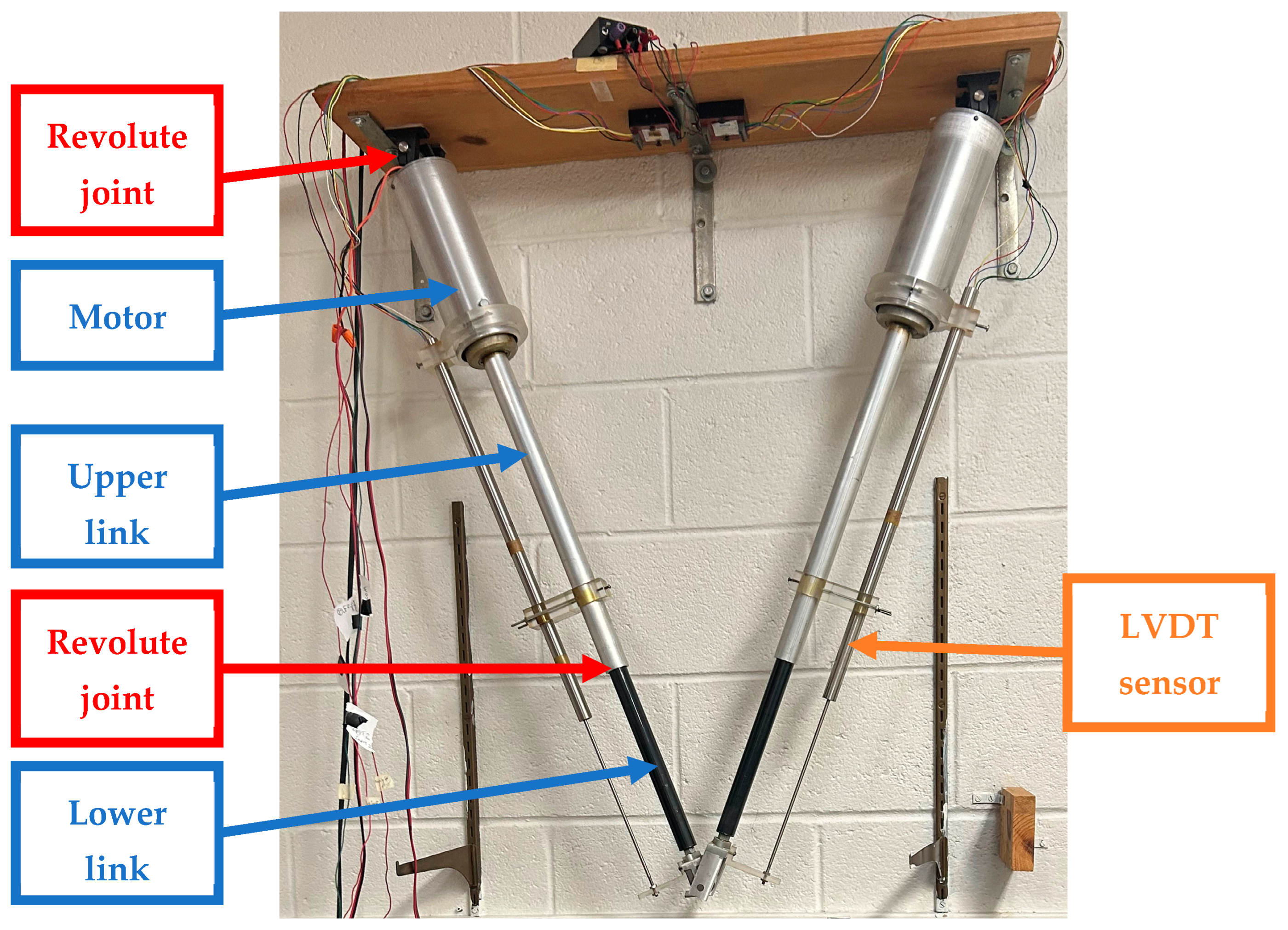
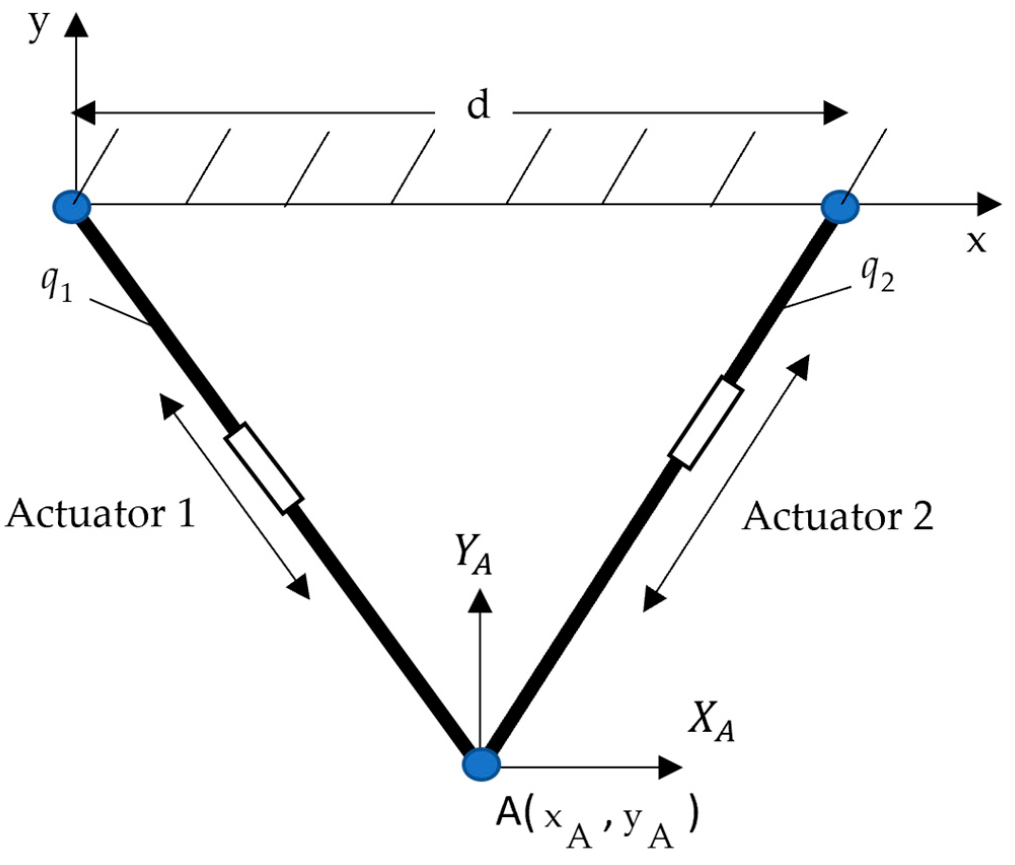
2. The Real 2-DOF CKCM

This section describes the main components of a real 2-DOF CKCM from the Robotics and Intelligent Control Laboratory (RICL) of the School of Engineering at the Catholic University of America (CUA). This manipulator was built as a prototype to demonstrate the capacity of the high-precision motion of CKCMs for potential applications in space assembly. Figure 1 shows the manipulator, consisting of two links, each composed of a ball screw linear actuator driven by a direct current (DC) motor. The top end of each link is suspended below a fixed platform, and the links are connected to the platform by two pin joints acting as revolute joints. The other ends of the links are coupled together by the same type of revolute joint on which an end-effector is mounted. Two linear voltage differential transformers (LVDT) mounted along the links serve as position sensors to provide real-time information on the link lengths. Table 1 presents the manipulator parameters and the specifications of the ball screw actuators.
The LVDT position sensors are precision linear variable differential transformers, encapsulated in a metal housing. An external Alternating Current (AC) source excites the primary, producing magnetic flux within the transducer. Consequently, this induces voltages in the two secondaries, whose magnitude varies with the position of the core. The secondaries are connected in series opposition, producing a total output voltage that is essentially zero when the core is at the electrical center of the unit and increases linearly when the core is displaced in either direction from the electrical center. The transducers can be excited at frequencies varying from 400 Hz to 10 kHz. Table 2 provides the main characteristics of the LVDTs.
Figure 2 illustrates a block diagram of the manipulator control system. Interfacing with the outside world, consisting of the robot manipulator, sensors, amplifiers, and computer processing unit, is performed through a data acquisition system (DAQ). The DAQ in this system is a NI BNC 2120 DAQ board (National Instruments, Austin, TX, USA) that can support two analog inputs and two analog outputs by BNC connections. The voltage of the input and output channels can be selected to be either unipolar (0 to 10 volts) or bipolar (±5 volts or ±10 volts). Following the Nyquist sampling theory and standard control system design guidelines that recommend sampling at least 5–10 times the maximum system frequency [30], the DAQ sampling rate is set to 1 KHz by the compatible software package LabView in the processing unit. This sampling rate is selected because the dominant motion frequencies of our system are below 100 Hz. LabView, version 2019, a graphical programming environment, allows data acquisition and real-time analysis to be performed.
The frame assignment of the manipulator is shown in Figure 3, where the lengths of its links, q 1 and q 2 , are denoted as its joint variables.
From Figure 3, we obtain the following:
q 1 = x 2 + y 2
q 2 = d x 2 + y 2
where d is the distance between the pin joints hanging the two actuators and (x, y) represents the Cartesian position of the manipulator.
Equations (1) and (2) provide a closed-form solution for the inverse kinematics, meaning that they can be used to calculate the link lengths q 1 and q 2 from the desired Cartesian position (x, y).
Additionally, from (1) and (2), the Cartesian variables x and y can be derived as follows.
x = q 1 2 q 2 2 + d 2 2 d
y = 4 d 2 q 1 2 q 1 2 q 2 2 + d 2 2 d
Equations (3) and (4) offer a closed-form solution for the forward kinematics, allowing the determination of a Cartesian position (x, y) based on the link lengths q 1 and q 2 .
We proceed to derive the dynamic model the manipulator. Its Lagrangian dynamic equations can be obtained as a special case of Equation (5) [31] with n = 2, as follows:
M ( q ) q ¨ t + C ( q , q ˙ ) q ˙ ( t ) + G ( q ) + F ( q , q ˙ ) = τ
with
τ ( t ) = τ 1   τ 2 T ;   q ( t ) = q 1   q 2 T
where τ i denotes the joint force of the ith actuator for i = 1,2.
The inertia matrix, the Centrifugal and Coriolis forces, and the friction and gravitational forces at two joints are given by the following [31]:
M = m 1 0 0 m 1 ,   C = 0 m l s ( q 2 - q 1 ) 3 v m l s ( q 2 - q 1 ) 3 v 0 ,   G = [ G 1   G 2 ] T
with
G 1 = ( m 1 g [ 2 v 1 q 1 2 ( q 1 l s + q 2 l s + 2 q 1 q 2 ) q 2 l s v 2 ] m g l s [ 2 q 1 2 v 1 ( q 1 + q 2 ) q 2 v 2 ] ) 4 d q 1 2 q 2 v
G 2 = ( m 1 g [ 2 v 1 q 2 2 ( q 1 l s + q 2 l s + 2 q 1 q 2 ) q 2 l s v 2 ] m g l s [ 2 q 2 2 v 2 ( q 1 + q 2 ) q 1 v 2 ] ) 4 d q 2 2 q 1 v
where v 1 , v 2 , and v are actuator coupling constraints that can be expressed as follows:
v 1 ( t ) = v 2 ( t ) = q 2 2 q 1 2 + d 2 ,   v ( t ) = 4 d 2 q 1 2 v 1 ( t )
F = F V 1 q ˙ 1 + F C 1 sgn ( q ˙ 1 ) F V 2 q ˙ 2 + F C 2 sgn ( q ˙ 2 ) .

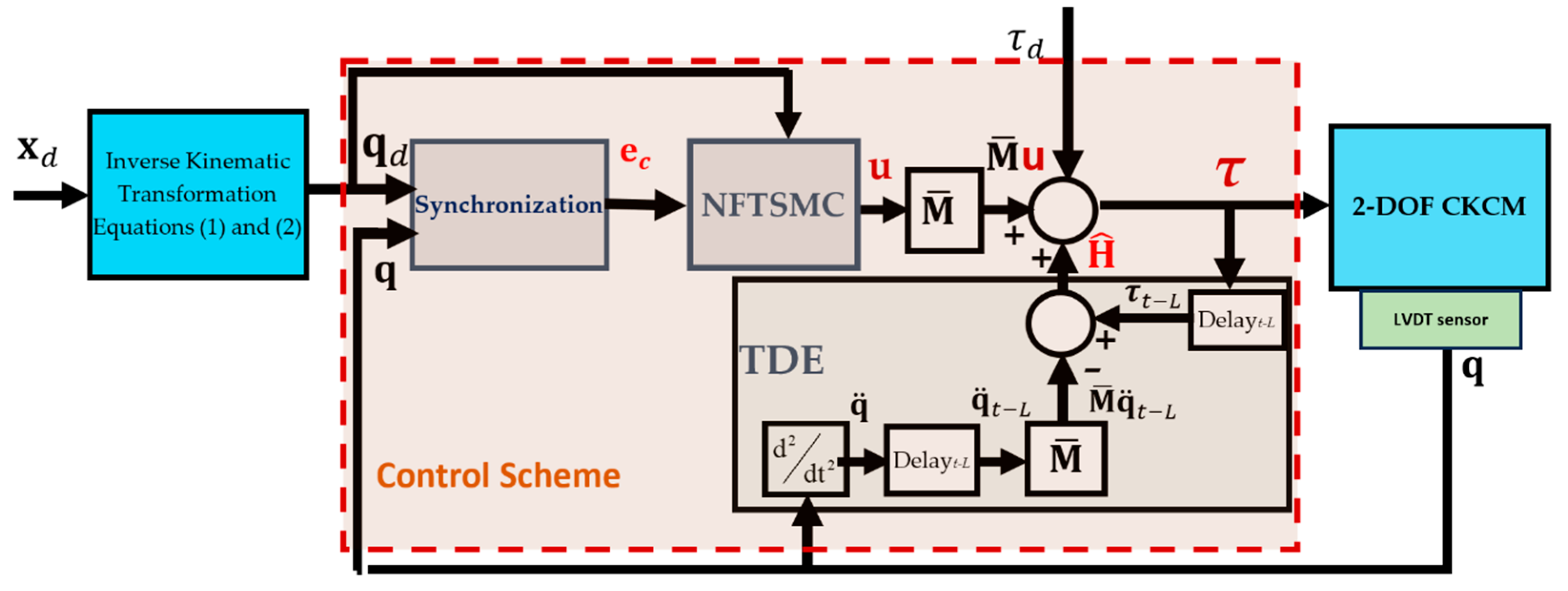
3. The Control Scheme

The Syn-TDE-NFTSMC scheme developed in [15] is now applied to control the motion of the manipulator described above in Section 2. As shown in Figure 4, the control system developed for the manipulator mainly consists of three subsystems: the Synchronization Subsystem, the NFTSMC Subsystem, and the TDE Subsystem.
The operation of the control system can be briefly explained as follows. As the input of the control scheme, the Cartesian vector x d R 2 representing the desired manipulator’s Cartesian configuration (position and orientation) is either specified by the user or generated by a trajectory planner. The vector x d is then converted into its corresponding joint vector q d R 2 through the Inverse Kinematic Transformation specified by Equations (1) and (2). The actual joint variables q 1 and q 2 acquired by the LVDTs constitute the actual joint vector q R 2 . Then, both the desired joint vector q d and the actual joint vector q are sent to the Synchronization Subsystem. This subsystem calculates the position error for each active joint e i = q d i q i for Joint 1 and Joint 2, the synchronization error e S , and the cross-coupling error e c between the two joints. The cross-coupling error e c R 2 is then processed by NFTSMC, which defines a sliding surface to regulate error behavior. Next, the control law u R 2 is formulated based on this sliding surface, ensuring that the system trajectory converges towards a stable hyperplane (sliding surface). This control law then serves as a key component of the input τ for the actuators of the manipulator to ensure asymptotic convergence of both position and synchronization errors in minimal time. Additionally, the TDE Subsystem utilizes past control inputs τ t L R 2 and the acceleration data q ¨ t L R 2 with M ¯ ( q ) R 2 × 2 , a constant, selected diagonal matrix of the estimated time delay L to estimate all nonlinear terms’ system dynamics H ^ R 2 , which include the inertia uncertainty, Coriolis/centripetal vector, gravitational vector, friction vector, disturbances, and disturbance torques τ d R 2 . These estimates are essential for generating the control input applied to the manipulator, ensuring robust and precise control performance under varying dynamic conditions.
We proceed to implement the Syn-TDE-NFTSMC scheme developed in [15] to control the motion of the manipulator. First the dynamics of the manipulator specified by (5) can be simplified as follows:
M ¯ q ¨ + H ( q , q ˙ , q ¨ ) = τ
where H ( q , q ˙ , q ¨ ) , including the manipulator dynamics with disturbance torques, can be denoted as follows:
H ( q , q ˙ , q ¨ ) = [ M ( q ) M ¯ ] q ¨ + C ( q , q ˙ ) q ˙ + G ( q ) + F ( q , q ˙ ) + τ d
Based on Figure 4 and according to [15], by using the TDE method, the nonlinear manipulator dynamic term H ( q , q ˙ , q ¨ ) can be approximated by the estimated term H ( q , q ˙ , q ¨ ) within a minimum time L, and a control law u can be added to the input τ to improve tracking accuracy and enhance robustness. Thus, the control input τ is derived from the following:
τ = H ( q , q ˙ , q ¨ ) + M ¯ u
where H ( q , q ˙ , q ¨ ) can be expressed based on (12), as follows:
H ( q , q ˙ , q ¨ ) = H ( q , q ˙ , q ¨ ) t L = τ t L M ¯ q ¨ t L
and the control law u is expressed as follows:
u = q ¨ d + q 2 p 2 K 2 I + α D 1 e ˙ c p 2 / q 2 1 1 1 + p 1 q 1 K 1 e c p 1 / q 1 1 e ˙ c + K s + K s w sign ( s )
with
s = e c + K 1 e c p 1 / q 1 + K 2 e ˙ c p 2 / q 2
q ¨ t L = q t 2 q t L + q t 2 L L 2
e c = e + α e s = ( I + α D ) e
and the parameters of u can be found in Table 3, below. Furthermore, we realize that H ̑ ( q , q ˙ , q ¨ ) constitutes the DTE and M ̄ u constitutes Syn-NFTSMC, as seen in Figure 4.
As shown in (14), the input τ to the manipulator consists of two primary components, a TDE-based input and an NFTSM input. The TDE-based component minimizes the influence of unknown dynamics in the manipulator dynamics, ensuring that the system can handle uncertainties in the model more effectively. On the other hand, the NFTSM component is designed to asymptotically drive both the cross-coupling errors e c and the tracking error e to converge to zero, thereby enhancing the accuracy of the control system over time.
Moreover, the application of TDE brings a further advantage to the control scheme. Instead of directly computing the complex and computationally intensive dynamic parameters H ( q , q ˙ , q ¨ ) , the TDE-based component can be derived with the estimate H ( q , q ˙ , q ¨ ) of H ( q , q ˙ , q ¨ ) using (15). This approach significantly improves the efficiency of the control system by minimizing the computational burden. By combining both the TDE-based and NFTSM components, the control system is able to handle both model uncertainties and the convergence of errors, providing a robust solution for controlling the manipulator.

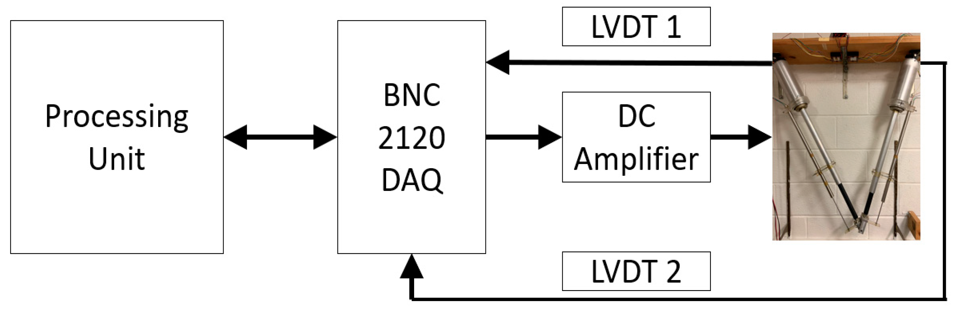
4. Experimental Study

This section presents an experimental study conducted to study the performance of the newly developed Syn-TDE-NFTSMC scheme in comparison with that of other existing control schemes when they are employed to control the motion of the manipulator.
In our experimental study, the newly developed Syn-TDE-NFTSMC scheme derived in (14), along with other existing control schemes described in Appendix A, were used to control the manipulator to track a circular trajectory over a duration of 45 s, specified by x d e s ( t ) and y d e s ( t ) as follows.
x d e s ( t ) = 0.3683 + 0.0383 cos ( 2 π t / 45 ) y d e s ( t ) = 0.9968 + 0.0381 sin ( 2 π t / 45 )
In order to use the optimized control parameters obtained from our simulation study for our experimental study, we intentionally selected the above circular motion, which was the same motion we used in our simulation study. In addition, we wanted to compare the results of the experimental study with those of the simulation study for the same motion.
In [15], computer simulation was performed to evaluate the performance of the newly developed Syn-TDE-NFTSMC scheme and several existing control schemes including LINEAR, TDE-based LINEAR, TDE-based LINEAR with synchronization errors, and TDE-based SMC with synchronization errors while tracking the same motion. Based on the simulation results, it was concluded that the control schemes that incorporated TDE and synchronization errors showed a better performance than conventional control schemes. Of all of the control schemes, Syn-TDE-NFTSMC delivered the desired trajectory with the smallest deviation from the desired motion and the fastest error convergence.
Thus, in this experimental study, we compared the performance of Syn-TDE-NFTSMC with two existing TDE-based control schemes with synchronization errors that were evaluated in the simulation, namely TDE-based LINEAR with synchronization errors (Syn-TDE-PID) and TDE-based SMC with synchronization errors (Syn-TDE-SMC), when tracking the same motion for a 2-DOF-CKCM.
The optimal control parameters obtained in the computer simulation [15] for the best tracking performance served as the basis for selecting the actual control parameters of the three control schemes in our experimental study.
In the experiments, since our control schemes are model-free, tuning the parameters was quite straightforward. The parameters of the control schemes were tuned as follows. Since M ¯ and α are diagonal matrices, these parameters could be tuned by increasing the diagonal elements from small positive values while checking the control performance by trial and error. Other parameters including p 1 , p 2 , q 1 , q 2 , K 1 , K 2 , and K were selected as described in [32] and Ksw was selected as described in [15].
After conducting numerous experiments with all three control schemes, the most optimal control parameters were finalized and are tabulated in Table 4.
The results of the experimental study are shown in Figure 5, Figure 6, Figure 7, Figure 8 and Figure 9 and Table 5, Table 6 and Table 7. These results were used for comparison with those of the computer simulation study conducted in [15]. In general, due to experimental conditions and real-world factors, such as sensor noise, environmental disturbances, actuator backlash, and mechanical limitations, the experimental results showed slightly higher tracking errors as compared to the computer simulation results. The details are presented below.
Figure 5, Figure 6, Figure 7, Figure 8 and Figure 9 indicate that incorporating TDE and synchronization errors greatly enhanced the performance of the control schemes. Our developed control scheme, Syn–TDE-NFTSMC, closely followed the desired trajectory (as seen in Figure 5) with minimal deviation from the desired path and demonstrated rapid error convergence.
We utilized MATLAB’s Data Statistics Tool, which can access experimental data from the window of the figure to compute the various errors.
Despite these practical challenges, the trends observed in the experiments largely align with those seen in the simulations. The Syn-TDE-PID strategy exhibited AATEs of 0.7 mm and 0.8 mm for Joint 1 and Joint 2, respectively. In comparison, the Syn-TDE-SMC and Syn-TDE-NFTSMC strategies demonstrated notable improvements, with errors of 0.127 mm and 0.129 mm for both joints. These experimental results further confirm that the control scheme outperformed the other existing approaches in terms of synchronization and control performance, achieving a reduction of up to 81% in maximum tracking error relative to the Syn-TDE-PID controller for Joint 1. The experimental results demonstrate that the Syn-TDE-NFTSMC controller is the most effective in reducing tracking errors in real-world applications, followed closely by Syn-TDE-SMC.
In the experimental setup, the trends observed in the simulation remain consistent, although the AASEs and AACEs are higher. Regarding synchronization errors, the Syn-TDE-PID controller shows the highest AASEs, with values of 0.24 mm and 0.32 mm for Joint 1 and Joint 2, respectively. In contrast, Syn-TDE-SMC and Syn-TDE-NFTSMC show smaller AASEs, with Syn-TDE-SMC having values of 0.134 mm and 0.19 mm, while Syn-TDE-NFTSMC delivers the best performance, with AASEs of 0.06 mm and 0.15 mm. The same trend is observed for AACEs, as shown in Table 6, where Syn-TDE-NFTSMC outperforms the other controllers. These results indicate that Syn-TDE-NFTSMC provides the most effective performance overall, minimizing both synchronization and cross-coupling errors in both simulation and experimental scenarios.
Table 7 presents the AAEE of the Syn-TDE-PID, Syn-TDE-SMC, and Syn-TDE-NFTSMC controllers in the experimental setup. In the simulation, the AAEE values remain identical across all three controllers, measuring 0.0177 Nm for Joint 1 and 0.0172 Nm for Joint 2. However, the experimental results show some variation compared to the simulation. Syn-TDE-PID exhibits the highest estimation error at 0.03 Nm, whereas Syn-TDE-SMC and Syn-TDE-NFTSMC achieve significantly lower errors of 0.01 Nm and 0.017 Nm, respectively, for Joint 1. A similar trend is observed for Joint 2 across all three control schemes. This indicates that, in the experimental study, Syn-TDE-SMC and Syn-TDE-NFTSMC provide more accurate estimation compared to Syn-TDE-PID.
In summary, the results demonstrate that the newly developed control scheme Syn-TDE-NFTSMC surpassed the performance of existing control schemes, as confirmed by comprehensive simulations and experimental validation on a 2-DOF CKCM. As expected, the experimental results show slightly higher tracking errors than those of the simulation, primarily due to experimental conditions and real-world factors, such as sensor noise, environmental disturbances, actuator backlash, and mechanical compliance. For instance, when acting as sensors the LVDTs theoretically offer infinite resolution, but in practice, limitations such as electronic noise and non-ideal behavior directly affect precision in trajectory tracking. In addition, unmodeled mechanical friction and delay in signal processing can also contribute to error accumulation. Although each individual factor was not fully isolated and quantified in this study, their combined effects are reflected in the increased average absolute tracking errors compared to the simulation. Nevertheless, the newly developed control scheme has proven to be highly accurate, straightforward to implement, and robust against parameter variations. Furthermore, the incorporation of synchronization errors significantly enhanced the overall performance of the control scheme, ensuring precise and reliable operation.

5. Conclusions

This paper focuses on the experimental performance evaluation of an advanced sliding mode control scheme, namely the Synchronization Time Delay Estimation Nonlinear Fast Terminal Sliding Mode Control (Syn-TDE-NFTSMC) scheme that was developed in [15]. Overall, by leveraging synchronization errors and integrating the Time Delay Estimation (TDE) method with a Nonsingular Fast Terminal Sliding Mode Controller (NFTSMC), the newly developed control scheme effectively minimized synchronization errors while maintaining computational efficiency. The TDE approach eliminated the need for the explicit computation of complex manipulator dynamics, making the control scheme particularly suitable for real-time applications. Furthermore, the stability of the control system was rigorously proven using the Lyapunov Theorem, ensuring uniform stability throughout its operation. The results of experiments conducted to evaluate the control performance of the newly developed control scheme when it was used to control the motion of a real 2-DOF CKCM showed that the newly developed control scheme outperformed existing control schemes. The obtained results underscore the practicality and reliability of the Syn-TDE-NFTSMC scheme for achieving precise synchronization and robust control in CKCMs. The ability to adapt to different manipulator configurations while reducing computational complexity further enhances its appeal for real-world robotic applications.
Future research directions include conducting an experimental study of the newly developed control scheme using manipulators with higher degrees of freedom (DOF). While the Syn-TDE-NFTSMC scheme has demonstrated a strong performance in a 2-DOF system, scaling it to higher-DOF manipulators poses new challenges. The new challenges could include increased computational demand, more complex joint interactions, and a higher burden on synchronization error estimation and time delay approximation. To address these challenges, future work could focus on algorithmic optimizations to maintain real-time performance and consider the application of adaptive and intelligent control techniques. These enhancements would aim to preserve the robustness and precision of the control strategy while ensuring scalability to more complex robotic platforms.

Author Contributions

Conceptualization, T.T.C.D., C.C.N. and T.D.T.; methodology, T.T.C.D. and C.C.N.; software, T.T.C.D. and C.C.N.; validation, T.T.C.D. and C.C.N.; results analysis, T.T.C.D. and T.D.T.; investigation, C.C.N., T.T.C.D. and T.D.T.; data curation, T.T.C.D. and T.D.T.; writing—original draft preparation, C.C.N., T.T.C.D. and T.D.T.; writing—review and editing, C.C.N. and T.T.C.D.; visualization, C.C.N. and T.T.C.D.; supervision, C.C.N. and T.T.C.D. All authors have read and agreed to the published version of the manuscript.

Funding

This research received no external funding.

Institutional Review Board Statement

Not applicable.

Informed Consent Statement

Not applicable.

Data Availability Statement

The original contributions presented in this study are included in the article. Further inquiries can be directed to the corresponding author.

Conflicts of Interest

All authors announce that they have no conflicts of interest in relation to the publication of this article.

Appendix A. Existing Control Schemes Used in Experimental Study

This appendix contains equations relevant to the control schemes to which the newly developed control scheme was compared in our experimental study.
  • TDE-based PID with synchronization errors (Syn-TDE-PID)
τ = τ t L M ¯ q ¨ t L TDE + M ¯ q ¨ d + K D e ˙ c + K P e c + K I e c d t PID   control
where
  • K D , K P , and K I are PID gain diagonal design matrices.
  • TDE-based SMC with synchronization errors (Syn-TDE-SMC) [13]
τ = τ t L M ¯ q ¨ t L TDE + M ¯ ( q ¨ d + K e ˙ c + K s w sign ( s ) + K 1 s ) SMC   control
where
  • The nonsingular terminal sliding surface is defined as follows:
s = e ˙ c + K e c .
  • K 1 , K , and K s w are diagonal design matrices.

References

  1. Patel, Y.D.; George, P.M. Parallel Manipulators Applications—A Survey. Mod. Mech. Eng. 2012, 02, 57–64. [Google Scholar] [CrossRef]
  2. Nguyen, C.; Pooran, F. Kinematic Analysis and Workspace Determination of a 6 dof CKCM Robot End-Effector. J. Mech. Work. Technol. 1989, 20, 283. [Google Scholar] [CrossRef]
  3. Nguyen, C.C.; Pooran, F.J. Dynamic analysis of a 6 DOF CKCM robot end-effector for dual-arm telerobot systems. Robot. Auton. Syst. 1989, 5, 377. [Google Scholar] [CrossRef]
  4. Nguyen, C.C.; Antrazi, S.S.; Zhou, Z.; Campbell, C.E. Adaptive control of a stewart platform-based manipulator. J. Robot. Syst. 1993, 10, 657. [Google Scholar] [CrossRef]
  5. Rodriguez-Angeles, A.; Nijmeijer, H. Mutual Synchronization of Robots via Estimated State Feedback: A Cooperative Approach. IEEE Trans. Control Syst. Technol. A Publ. IEEE Control Syst. Soc. 2004, 12, 542–554. [Google Scholar] [CrossRef]
  6. Sun, D.; Mills, J.K. Adaptive synchronized control for coordination of multirobot assembly tasks. IEEE Trans. Robot. Autom. A Publ. IEEE Robot. Autom. Soc. 2002, 18, 498–509. [Google Scholar]
  7. Doan, Q.V.; Le, T.D.; Vo, A.T. Synchronization Full-Order Terminal Sliding Mode Control for an Uncertain 3-DOF Planar Parallel Robotic Manipulator. Appl. Sci. 2019, 9, 1756. [Google Scholar] [CrossRef]
  8. Koren, Y. Cross-coupled biaxial computer control for manufacturing systems. J. Dyn. Syst. Meas. Control 1980, 102, 265–272. [Google Scholar] [CrossRef]
  9. Su, Y.; Sun, D.; Ren, L.; Mills, J. Integration of saturated PI synchronous control and PD feedback for control of parallel manipulators. IEEE Trans. Robot. A Publ. IEEE Robot. Autom. Soc. 2006, 22, 202. [Google Scholar]
  10. Zhao, D.; Li, S.; Gao, F. Fully adaptive feedforward feedback synchronized tracking control for Stewart Platform systems. Int. J. Control Autom. Syst. 2008, 6, 689–701. [Google Scholar]
  11. Su, Y.X.; Sun, D.; Ren, L.; Wang, X.; Mills, J.K. Nonlinear PD Synchronized Control for Parallel Manipulators. In Proceedings of the 2005 IEEE International Conference on Robotics and Automation, Barcelona, Spain, 18–22 April 2005. [Google Scholar]
  12. Duong, T.T.C.; Nguyen, C.C.; Thien, T.D. An Advanced PD Controller for Robot Manipulators with Time-Delay Estimation. In Proceedings of the 2022 World Automation Congress (WAC), San Antonio, TX, USA, 11–15 October 2022. [Google Scholar]
  13. Duong, T.T.C.; Thien, T.D.; Tri, N.T.; Nghi, D.V. Synchronization Sliding Mode Control with Time-Delay Estimation for a 2-DOF Closed-Kinematic Chain Robot Manipulator. In Proceedings of the 2021 International Conference on System Science and Engineering (ICSSE), Ho Chi Minh City, Vietnam, 26–28 August 2021. [Google Scholar]
  14. Tran, D.T.; Dao, H.V.; Ahn, K.K. Adaptive synchronization sliding mode control for an uncertain dual-arm robot with unknown control direction. Appl. Sci. 2023, 13, 7423. [Google Scholar] [CrossRef]
  15. Duong, T.T.C.; Nguyen, C.C.; Tran, T.D. Synchronization Sliding Mode Control of Closed-Kinematic Chain Robot Manipulators with Time-Delay Estimation. Appl. Sci. 2022, 12, 5527. [Google Scholar] [CrossRef]
  16. Dinh, T.X.; Thien, T.D.; Anh, T.H.V.; Ahn, K.K. Disturbance Observer Based Finite Time Trajectory Tracking Control for a 3 DOF Hydraulic Manipulator Including Actuator Dynamics. IEEE Access 2018, 6, 36798–36809. [Google Scholar] [CrossRef]
  17. Nuño, E.; Basañez, L.; Ortega, R. Adaptive control for the synchronization of multiple robot manipulators with coupling time-delays. In Proceedings of the 2010 IEEE/RSJ International Conference on Intelligent Robots and Systems, Taipei, Taiwan, 18–22 October 2010. [Google Scholar]
  18. Zhao, D.; Li, S.; Gao, F. A new terminal sliding mode control for robotic manipulators. Int. J. Control 2009, 82, 1804. [Google Scholar] [CrossRef]
  19. Zhihong, M.; Paplinski, A.; Wu, H. A robust MIMO terminal sliding mode control scheme for rigid robotic manipulators. IEEE Trans. Autom. Control 1994, 39, 2464. [Google Scholar] [CrossRef]
  20. Tang, Y. Terminal sliding mode control for rigid robots. Automatica 1998, 34, 51. [Google Scholar] [CrossRef]
  21. Xia, Y.; Zhang, J.; Lu, K.; Zhou, N. Finite Time and Cooperative Control of Flight Vehicles, 1st ed.; Advances in Industrial Control; Springer: Singapore, 2019; p. 400. [Google Scholar]
  22. Shtessel, Y.; Edwards, C.; Fridman, L.; Levant, A. Sliding Mode Control and Observation; Birkhäuser: Basel, Switzerland, 2014. [Google Scholar]
  23. Yang, L.; Yang, J. Nonsingular fast terminal sliding-mode control for nonlinear dynamical systems. Int. J. Robust Nonlinear Control 2011, 21, 1865. [Google Scholar] [CrossRef]
  24. Van, M.; Ge, S.S.; Ren, H. Finite Time Fault Tolerant Control for Robot Manipulators Using Time Delay Estimation and Continuous Nonsingular Fast Terminal Sliding Mode Control. IEEE Trans. Cybern. 2017, 47, 1681. [Google Scholar] [CrossRef]
  25. Zhao, D.; Li, S.; Gao, F. Finite time position synchronised control for parallel manipulators using fast terminal sliding mode. Int. J. Syst. Sci. 2009, 40, 829. [Google Scholar] [CrossRef]
  26. Hsia, T.; Lasky, T.; Guo, Z. Robust independent joint controller design for industrial robot manipulators. IEEE Trans. Ind. Electron. A Publ. IEEE Ind. Electron. Soc. 1991, 38, 21. [Google Scholar] [CrossRef]
  27. Baek, J.; Cho, S.; Han, S. Practical Time-Delay Control with Adaptive Gains for Trajectory Tracking of Robot Manipulators. IEEE Trans. Ind. Electron. A Publ. IEEE Ind. Electron. Soc. 2018, 65, 5682. [Google Scholar] [CrossRef]
  28. Bae, H.-J.; Jin, M.; Suh, J.; Lee, J.Y.; Chang, P.-H.; Ahn, D.-S. Control of Robot Manipulators Using Time-Delay Estimation and Fuzzy Logic Systems. J. Electr. Eng. Technol. 2017, 12, 1271. [Google Scholar] [CrossRef]
  29. Jin, M.; Lee, J.; Chang, P.H.; Choi, C. Practical Nonsingular Terminal Sliding-Mode Control of Robot Manipulators for High-Accuracy Tracking Control. IEEE Trans. Ind. Electron. A Publ. IEEE Ind. Electron. Soc. 2009, 56, 3593. [Google Scholar]
  30. Martinez, D.R.; Bond, R.A.; Vai, M.M. High Performance Embedded Computing Handbook: A Systems Perspective; CRC Press: Boca Raton, FL, USA, 2018. [Google Scholar]
  31. Jabbari, P.F. Dynamics and Control of Robot Manipulators with Closed-Kinematic Chain Mechanism. Ph.D. Thesis, Catholic University of America, Washington, DC, USA, 1990. [Google Scholar]
  32. Feng, Y.; Yu, X.; Man, Z. Non-singular terminal sliding mode control of rigid manipulators. Automatica 2002, 38, 2159. [Google Scholar] [CrossRef]
Figure 1. The 2-DOF CKCM.
Applsci 15 05206 g001
Figure 2. The closed-loop control system of the manipulator.
Applsci 15 05206 g002
Figure 3. The frame assignment of the planar 2-DOF CKCM.
Applsci 15 05206 g003
Figure 4. The Syn-TDE-NFTSMC scheme used to control the 2-DOF CKCM.
Applsci 15 05206 g004
Figure 5. Trajectory tracking in the X-Y planes of the control schemes used in the experimental study (circular motion).
Applsci 15 05206 g005
Figure 6. The time trajectories of the tracking errors of the control schemes of Joint 1 (a) and Joint 2 (b) in the experimental study.
Applsci 15 05206 g006
Figure 7. The time trajectories of the synchronization errors and cross-coupling errors of the control schemes of Joint 1 (a) and Joint 2 (b) in the experimental study.
Applsci 15 05206 g007
Figure 8. The time trajectories of the estimation errors of the control schemes of Joint 1 (a,c) and Joint 2 (b,d) in the experimental study.
Applsci 15 05206 g008
Figure 9. The control input signals of the control schemes of Joint 1 and Joint 2 in the experimental study.
Applsci 15 05206 g009
Table 1. The manipulator parameters and actuator specifications.
Manipulator
Parameters
DescriptionValueUnit
m Link’s total mass4.91kg
m 1 Link’s moving part mass0.59kg
d Ground’s horizontal distance0.74m
l s Link’s fixed length0.26m
gGravitational acceleration constant9.81m/s2
Link’s minimum length0.84m
Link’s maximum length1.22m
Actuator
Specifications
DescriptionValueUnit
MotorPermanent magnet
Voltage24 VDCVDC
Speed3000 RPMRPM
Diameter0.076m
Stroke0.406m
Gear reduction10:1
Max velocity1.78cm/second
Table 2. The specifications of the LVDTs.
LVDTDescriptionValueUnit
Linear range±7.5inch
LinearityBest fit straight line
ResolutionInfinite (theoretically)
Input±14.5 to ±28 VDC, ±100 mA
Output±5VDC
Operating temperature range−67 to 257F
Table 3. The symbols, specifications, and parameters.
ParameterDescriptionFormula
τ ( t ) R 2 Joint force vector τ ( t ) = ( τ 1   τ 2 ) T
τ t L R 2 Past joint force vector τ t L = ( τ ( t L ) 1   τ ( t L ) 2 ) T
K 1 ,   K 2 , K ,   and   K s w 2 × 2 diagonal design matrices K 1 = K 11 0 0 K 22 ; K 2 = K 21 0 0 K 22 K = K 11 0 0 K 22 ; K s w = K s w 11 0 0 K s w 22
p 1 ,   p 2 ,   q 1 ,   and   q 2 Positive odd integers 1 < p 1 / q 1 < 2 ; 1 < p 2 / q 2 < 2
u R 2 Control law vector u = u 1   u 2 T
s R 2 Nonsingular terminal sliding surface vector s = s 1 ,   s 2 T
sign ( s ) R 2 Sign function of sliding surface vector sign ( s ) = sign ( s 1 ) , , sign ( s n ) T
q ¨ t L R 2 Past acceleration vector q ¨ t L = q ¨ t L 1 , q ¨ t L 2 T
q ¨ d R 2 Desired acceleration joint vector q ¨ d = q ¨ d 1 , q ¨ d 2 T
p 1 ,   p 2 ,   q 1 ,   and   q 2 Positive odd integers 1 < p 1 / q 1 < 2 ; 1 < p 2 / q 2 < 2
α R 2 × 2 Diagonal positive definite matrix α = α 2 0 0 α 2
I R 2 × 2 Identity matrix I = 1 0 0 1
D R 2 × 2 Synchronization transformation matrix D = 1 1 1 1
e R 2 Tracking error vector e = e 1 ,   e 2 T
e s R 2 Synchronization error vector e s = e s 1 ,   e s 2 T
e c R 2 Cross-coupling error vector e c = e c 1 ,   e c 2 T
Table 4. The parameters of the control schemes used in the experimental study, computed by MATLAB, version 2019.
Control SchemesControl Parameters
Syn-TDE-PID L = 9.999 × 10 4 s, M ¯   =   diag ( 0.9 ,   0.9 ) ,   K P   =   diag ( 50 ,   45 ) ,   K i   =   diag ( 0.4 ,   0.5 ) ,   K D   =   diag ( 3 ,   2.5 ) ,   α = diag(0.5, 0.5)
Syn-TDE-SMC L = 9.999 × 10 4 s, M ¯   =   diag ( 0.3 ,   0.25 ) ,   K 1   =   diag ( 25 ,   20 ) ,   K   =   diag ( 9 ,   9 ) ,   K s w   =   diag ( 8 ,   12 ) ,   α = diag(0.5, 0.5)
Syn-TDE-NFTSMC L = 9.999 × 10 4 s ,   p 1 = 19 ,   p 2 = 11 ,   q 1 = 17 ,   q 2 = 9 ,   M ¯ = diag ( 0.3 ,   0.25 ) ,   K 1 = diag ( 25 ,   25 ) ,   K 2 = diag ( 20 ,   20 ) ,   K = diag ( 9 ,   9 ) ,   K s w = diag ( 8 ,   12 ) ,   α = diag(0.5, 0.5)
Table 5. The absolute average tracking errors (AATE) of the control schemes in the experimental study, computed by MATLAB.
Tracking Errors Syn-TDE-PIDSyn-TDE-SMCSyn-TDE-NFTSMC
e 1 (mm)0.70.20.127
e 2 (mm)0.80.180.13
Table 6. The absolute average synchronization errors (AASE) and cross-coupling errors (AACE) of the control schemes used in the experimental study, computed by MATLAB.
Errors Syn-TDE-PIDSyn-TDE-SMCSyn-TDE-NFTSMC
e s 1 (mm)0.240.1340.06
e s 2 (mm)0.320.190.15
e c 1 (mm)0.770.210.2
e c 2 (mm)0.910.490.27
Table 7. The absolute average estimation errors (AAEE) of the Syn-TDE-NFTSMC scheme computed by MATLAB.
AAEE Syn-TDE-PIDSyn-TDE-SMCSyn-TDE-NFTSMC
e e s t 1 (Nm)0.030.010.017
e e s t 2 (Nm)0.0020.00060.0006
Disclaimer/Publisher’s Note: The statements, opinions and data contained in all publications are solely those of the individual author(s) and contributor(s) and not of MDPI and/or the editor(s). MDPI and/or the editor(s) disclaim responsibility for any injury to people or property resulting from any ideas, methods, instructions or products referred to in the content.

