1. Introduction
The significant contribution of coal to power generation is attributed to its widespread availability and abundance as a solid fossil fuel in many countries. Coal as a main fuel source accounted for 35.51% of the world’s electricity generation and 36.91% of Turkey’s electricity generation in 2023 [
1]. It is clear that coal is an integral part of the global energy balance and cannot be ignored, as it is not only an accessible energy source in many countries but also an indispensable one for certain industries. In other words, technological advancements concerning coal should focus on finding environmentally friendly and efficient ways to use coal. Plasma combustion technology is one such method used to ignite pulverized coal and ensure flame stabilization [
2,
3,
4,
5,
6,
7,
8,
9,
10,
11,
12]. Through the application of this technology, it is possible to eliminate the use of fuel oil or gas during boiler start-up and to stabilize pulverized coal combustion. The amount of fuel oil consumed per boiler start-up depends on the boiler’s steam generation capacity [
13]. According to the cold start-up procedure, which aims to heat the boiler and ensure stable operation of the main coal burners, approximately 8 tons of fuel oil are consumed during the start-up of a boiler, producing 96 t/h of steam. This consumption increases to about 40 tons for a boiler producing 525 t/h and up to 200 tons for a boiler producing 810 t/h. To eliminate fuel oil use during start-up and ensure flame stabilization in case of operational failures or changes in coal properties, auxiliary burners supported by plasma technologies are used. This technology utilizes plasma generated by electric arc or microwave energy to heat the air–coal mixture to a temperature at which the volatiles in the coal are released and ignition occurs.
Numerous papers focusing on coal ignition and flame stabilization by plasma technology have been published worldwide [
14,
15,
16,
17,
18,
19,
20], and this technology is widely applied in China [
21]. In [
14], experiments were conducted to determine the ignition and combustion conditions of high-reactivity, low-ash brown coal (ash content up to 15%) using plasma technology. The results confirmed stable ignition and combustion of pulverized coal with plasma generated by an electric arc. An industrial prototype plasma combustion system was designed and tested on a 220 t/h steam capacity boiler, successfully eliminating the need for fuel oil during cold start-up. A stable flame at 1350 °C was achieved inside the boiler. In [
15], the authors investigated the use of plasma technology for cold start-up in a pilot plant burning pre-dried, low-ash lignite. A swirl burner using an electric arc plasma torch with a power range of 4 to 7 kW was designed and tested for pulverized coal combustion. The study examined the effects of fuel moisture and particle size, showing that lignite with up to 20% moisture and a particle size below 450 μm could be stably ignited. However, flame instability was observed with lower-quality lignite. Articles [
16,
17] assessed the potential for improving boiler efficiency by applying plasma combustion technologies to ignite highly reactive, low-ash coal (15%) and reduce unburned fuel. Using CFD, a model of the combustion chamber with twelve tangential burners and two plasma burners was developed. The application of plasma combustion technology led to a more uniform temperature and velocity distribution at the combustion chamber exit. The average exit temperature increased from 1220 °C to 1260 °C, indicating a more intense combustion of the pulverized coal. The use of plasma combustion technologies to enhance the efficiency of thermal power plant units may be economically viable, as plasma systems are considerably more cost-effective than traditional fuel oil. However, the authors emphasize the need for further research on the feasibility of plasma combustion technology before such systems can be implemented. In [
18], the plasma ignition of highly reactive lignite dust particles in a flat flame burner was studied using a high-voltage DC plasma torch with a rod electrode. The calculations indicated that the coal ignition delay time decreased by 0.8–3.5 ms, depending on the ambient temperature, which ranged from 1200 K to 1800 K. The study examined the effects of both chemical and thermal factors on coal ignition, revealing that the thermal effect dominates. Experimental results showed that as the ambient temperature increased from 1200 K to 1800 K, the ignition delay time reduced from 2.9 ms to 1.2 ms, which aligns with the calculated predictions. In [
19], the plasma ignition of coal using an alternating current (AC) plasma torch was tested to reduce fuel oil consumption in a pulverized coal boiler at a power plant. Experiments were conducted to evaluate the electrode service life of the AC plasma torch, with the operating life of the electrodes determined to be 530 h. The plasma burner was specifically designed to ignite low-ash, low-quality coal through the staged combustion principle. To assess the impact on combustion characteristics such as plasma torch power, combustion temperature, and carbon burnout rate, the power was varied between 150 kW and 300 kW. At 300 kW plasma torch power, a flame temperature of 940 °C and a carbon burnout rate of 52.2% were achieved with a coal torch length of 6.3 m. These results confirmed the effectiveness of igniting low-quality coal using an oil-free AC plasma torch. In [
20], the FLOREAN program for CFD modeling was used to compare two combustion modes in a pulverized coal boiler with a steam capacity of 160 t/h: conventional combustion of low-quality coal (30% ash content) using eight tangential burners arranged in two levels, and combustion with plasma fuel systems installed in two opposite burners on the lower level. The calculations provided temperature, velocity, and concentration fields for carbon oxides (CO) and nitrogen oxides (NO) in the boiler furnace. The study demonstrated that plasma combustion systems can effectively reduce harmful CO and NO emissions when burning low-quality coal. It is important to note that plasma combustion technology is primarily studied through numerical-theoretical methods and laboratory-scale experimental research.
Plasma combustion technology has been widely adopted in thermal power plants by the Chinese company LY Power, located in Yantai city, Shandong Province, China, which, by 2020, had implemented this technology in 862 power units, including 31 units across the Republic of Korea, Russia, Southeast Asia, Europe, and Africa [
21]. These units have a total installed capacity exceeding 370 GW. LY Power also developed the world’s first oil-free thermal power plant using plasma combustion technology. This system eliminates the need for fuel oil in both boiler start-up and the stabilization of the pulverized coal flame. However, a limitation of LY Power’s plasma combustion technology is that the ash content of the coal being burned must not exceed 30%.
The reviewed articles indicate that, in laboratory, pilot, and industrial-scale applications, plasma was produced through electric arcs generated by AC (alternating current) or DC (direct current) technologies. However, a common limitation noted for both methods is the relatively short service life of the electrodes.
In this regard, a novel burner design employing plasma combustion technology, based on the ionization of air using microwave energy to produce plasma, is proposed in this study as a replacement for traditional auxiliary burners. The proposed burner features an internal combustion system and multi-stage ignition process to enhance flame stability, improve combustion efficiency, and enable more controlled coal burning within the plasma. To determine the optimal operating parameters of the novel auxiliary burner, a test setup was established in Unit-1 22 MWe of the Soma A Thermal Power Plant, and integrated into a newly designed pulverized coal storage system. In this setup, the coal used in the original boiler design was utilized instead of traditional fuels like fuel oil or gas for initial ignition and flame stabilization in thermal power plant boilers.
Overall, these findings demonstrate that the proposed auxiliary burner design has the potential to be a more environmentally friendly and efficient alternative to conventional burners in the start-up process of pulverized coal-fired boilers and in ensuring flame stabilization.
3. Materials and Methods
The first step in determining the optimal operating parameters of the burner began with separately measuring the velocities of the secondary air, primary air, and the mixture of primary air and pulverized coal within the pipe. Next, the primary air and pulverized coal mixture sample was taken from the pipe according to the ASME PTC 4.2 Coal Sampling Standard [
22]. Pulverized coal samples taken from the pipe were prepared under laboratory conditions for analysis according to the ASTM D 2013 coal sample preparation standard [
23]. The proximate analyses of the pulverized coals prepared for analysis, including moisture (ASTM D 3173), ash (ASTM D 3174), volatile matter (ASTM D 3175), and gross calorific value (ASTM D 5865), were performed according to the analysis methods specified in the standards [
23]. Additionally, a sieve analysis was performed to determine the particle size distribution of the pulverized coal. The optimal operating parameters of the burner were determined based on the evaluation of the data obtained from the analyses.
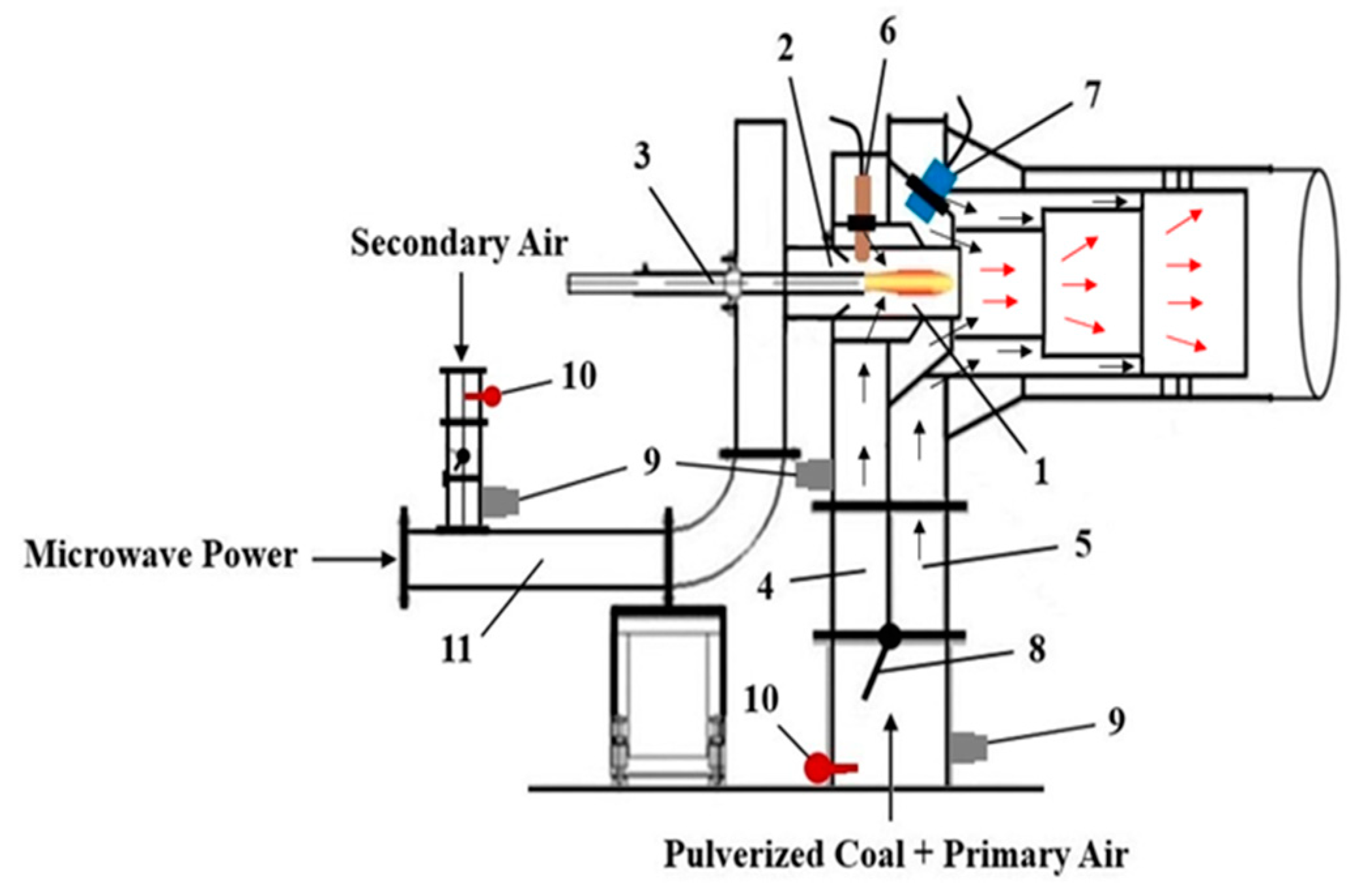
The velocity of the pulverized coal and primary air mixture was measured at the measurement port, indicated as number 9 in
Figure 1, which is mounted at the burner inlet.
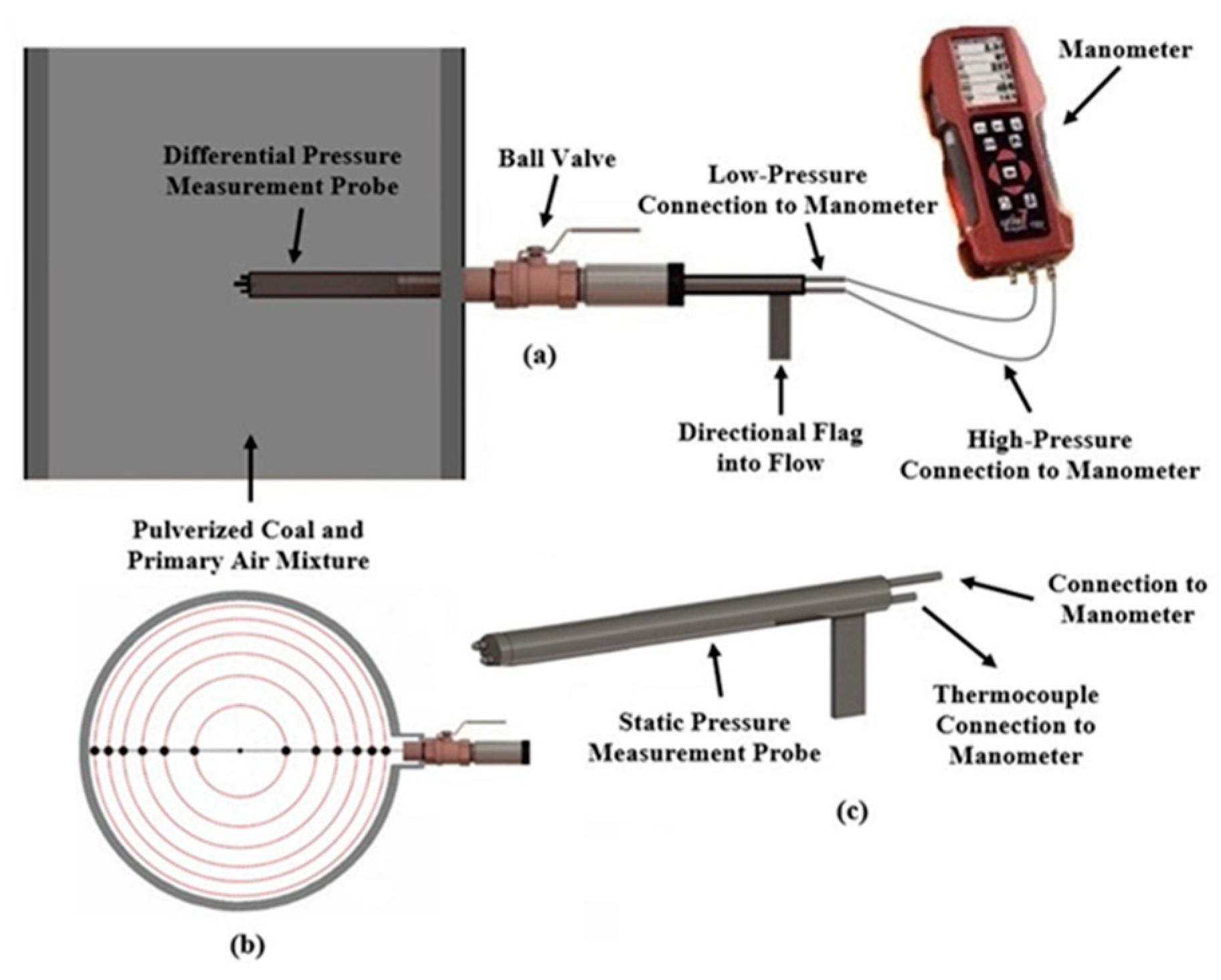
Figure 3 shows the pipe cross-section, differential, and static pressure measurement equipment.
The differential pressure probe shown in
Figure 3a was inserted into the pipe through the measurement port, perpendicular to the flow of the pulverized coal–air mixture according to the ASME PTC 4.2 standard [
22]. As shown in
Figure 3b, the interior of the circle is divided into circles with equal areas on the axial axis. The differential pressure values measured by the probe at the points where the outer circumference of these equal-area circles intersect the radial axis of the pipe were recorded.
After the measurement, the average of the differential pressure values measured along the radial axis was taken. The static pressure and temperature values inside the pipe were measured using the static pressure probe shown in
Figure 3c. The probe was inserted into the pipe through the measurement port perpendicular to the flow of the pulverized coal-air mixture and pushed to the center of the pipe. The static pressure and temperature values were recorded from the manometer connected to the probe. The air density inside the pipe was calculated by applying the measured static pressure and temperature values to the ideal gas equation in (1). The air velocity inside the pipe was determined by applying the air density, the average differential pressure value, and the probe’s k correction factor to the Bernoulli equation in (2). The airflow rate was obtained by multiplying the air velocity inside the pipe by the pipe’s cross-sectional area.
where,
P: Static Pressure (Pa),
R: Universal gas constant (R = 287 J/kgK),
T: Fluid Temperature (K),
ρ: Fluid Density (kg/m3).
The simplest form of the Bernoulli Equation (2) is:
In the Bernoulli Equation (2), when the initial velocity is zero and the differential pressure measurement probe moves along the x-axis, the fluid’s velocity at the second point is calculated according to Equation (3): (h
1, h
2 = 0, V
1 = 0).
where,
V2: Fluid velocity (m/s),
k: Probe coefficient (k = 0.92),
ΔP: The average differential pressure values measured at the measurement port (Pa),
ρ: Fluid Density (kg/m3)
In determining the burner’s operating parameters, it is crucial to focus on employing an accurate and standardized coal pipe sampling method. According to the ASME PTC 4.2 Coal Sampling Standard [
22], isokinetic sampling ensures that the pulverized coal enters the sample container through the opening at the tip of the coal sampling probe in
Figure 4a and is collected at the same velocity as the coal air mixture passing through the pipe, which best represents the sampling conditions. The isokinetic coal sampling test begins with marking off the pulverized coal lines to be sampled for an equal area traverse.
Figure 4b illustrates coal sampling at 48 points along the axial axis of the coal pipe, which has been divided into equal areas.
To extract the coal from inside the pipe isokinetically, the suction velocity at the probe tip must equal the velocity of the coal-air mixture within the pipe. In
Figure 4, measurements are taken at 12 different points at each measurement port. The ejector suction pressure is calculated separately for each measurement port using Equation (4).
where,
SPE: Section Pressure of the ejector (Pa),
N: The number of points at each measurement port,
k: Probe coefficient (k = 0.92),
The differential pressure value at each measurement point (Pa).
To keep the speed at the end of the coal sampling probe constant, the ejector differential pressure must be maintained at a constant value. To achieve this, there is an adjustable ball valve before the ejector. When this valve is continuously adjusted, the speed at the end of the coal sampling probe is kept constant. The area of the opening at the end of the coal sampling probe is 1.95 × 10⁻
4 m
2. Pulverized coal particles collected isokinetically from the pipe enter the cyclone and then accumulate in the collection chamber beneath the cyclone. The total coal flow rate in the measurement pipe is calculated using Equation (5).
where,
TCF: Total Coal Flow (kg/h),
TSW: Total Sample Weight (g),
CAP: Cross-sectional area of the pipe (m2),
CASP: Cross-sectional area of the coal sampling probe (m2),
TNP: Total number of ports used in the measurement,
NSP: Number of sampling points at each port,
t: Sampling time at each point (s).
According to this standard, ports placed on the pipe should be positioned at a distance away from elbows or points where the flow direction changes. The coal–air mixture is typically not homogeneous in pulverized coal power plants. The coal–air mixture can flow in a roping form, causing the mixture to concentrate in certain areas of the pipe, affecting sampling efficiency. In this case, sampling from additional ports can minimize measurement errors. According to this standard, the measurement error for static pressure is ±5 mm WC, the measurement error for coal sampling is ±5%, the measurement error for coal flow is ±10%, the measurement error for airflow is ±5%, and the measurement error for temperature is ±2 °C.
4. Results and Discussion
The experiments were conducted as follows: Secondary air, which can be gradually increased to 1000 Nm
3/h using an electronically controlled fan, was delivered into the burner. During the measurements, the temperature of the secondary air drawn from the atmosphere, which was used as the working gas, was 30 °C. As shown in
Figure 1, the pipe diameter through which the secondary air enters is 150 mm. The secondary air velocities, which were gradually increased, were measured at the same port on the pipe. After repeated measurements, the secondary air flow rates obtained from eight separate measurements are shown in
Table 1.
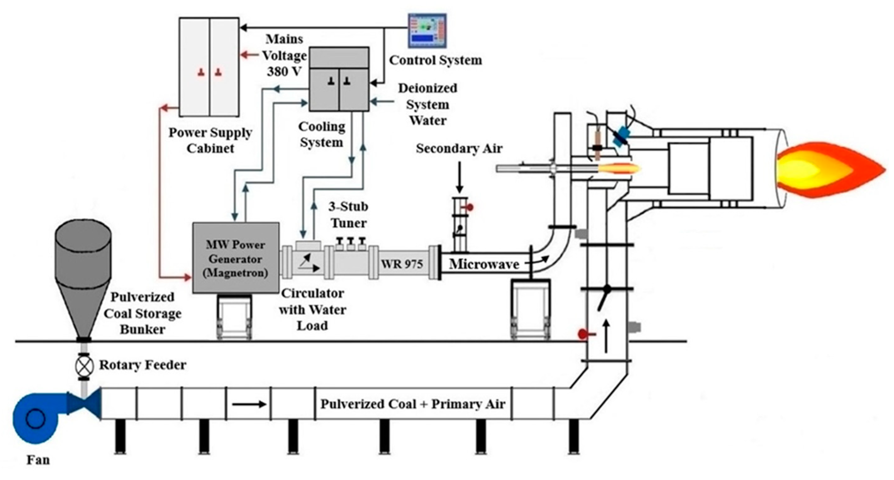
To form the plasma flame, the secondary air was directed into the burner through a 150 mm diameter pipe using an automatically controlled fan. Then, the magnetron power was set to 18.75 kW, which is 25% of its total power of 75 kW, and maintained at this level, with the frequency set to 915 MHz. A spark is created when a metal rod with a copper tip, moved by a double-acting pneumatic valve operated with compressed air, strikes the metal rod made of tungsten in the center of the coaxial line. Microwave energy transforms the secondary air, serving as the working gas, into plasma near the open end of the coaxial line through the spark generated. After the formation of plasma, the magnetron power is increased to 37.5 kW, which is 50% of the total power. The ignition process was then repeated with a gradual increase in the airflow rate. When the secondary air flow rate reached 250 Nm3/h, the first plasma flame was obtained. About 3 min after the initial plasma formation was observed, an overcurrent fault signal appeared on the control system, causing the magnetron to deactivate. When the air flow rate was increased to 350 and 450 Nm3/h, the control system detected an overcurrent fault, similar to what occurred at an airflow rate of 250 Nm3/h, resulting in the automatic shutdown of the magnetron in both attempts. When the air flow rate is increased to 500 Nm3/h and ignition is performed, plasma forms, and no overcurrent fault signal is observed during ignitions at various air supply rates ranging from 500 Nm3/h to 1000 Nm3/h.
During the ignition tests, the three-stub tuner was adjusted each time to minimize the reflected power. The evaluation of the results determined that the airflow rate of the secondary air directed to the burner as a working gas should be at least 500 Nm3/h.
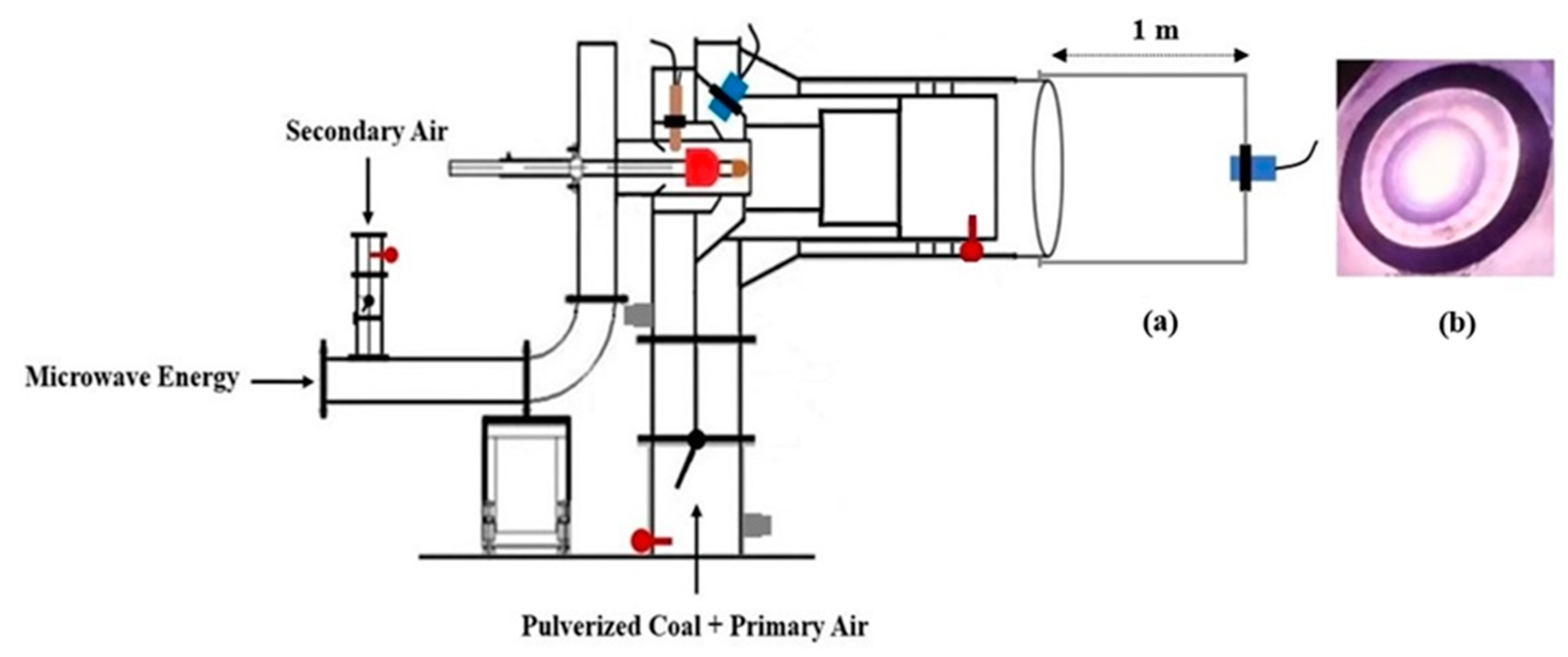
A high-resolution camera was temporarily mounted 1 m away from the burner outlet, as shown in
Figure 5a, to observe the transformation of secondary air entering the burner through direct flow into plasma. When the air flow rate was increased to 500 Nm
3/h and ignition is performed, plasma forms as shown in
Figure 5b.
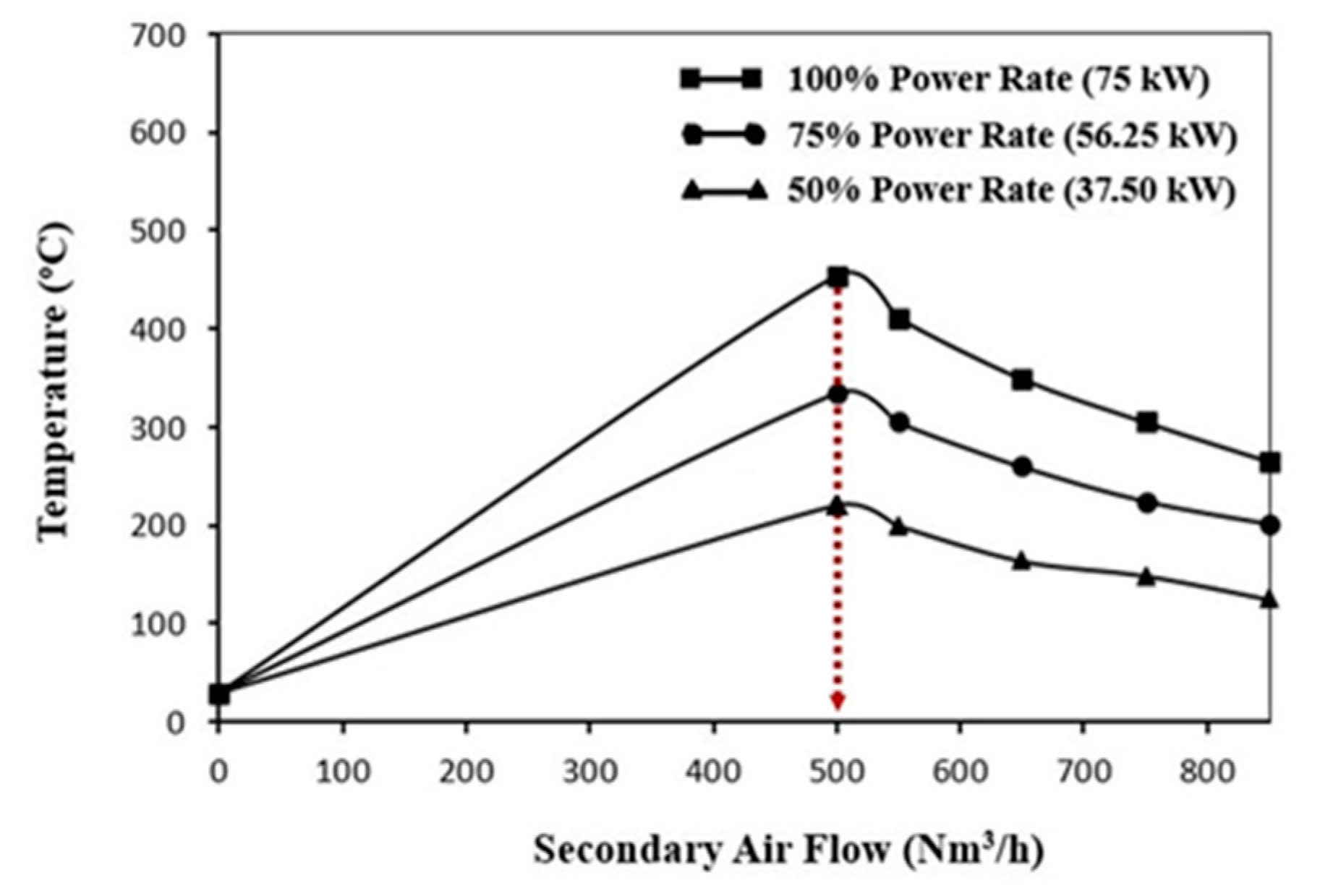
The temperature of the plasma flame formed at different air flow rates via an electronically controlled fan was measured using a thermocouple mounted at the burner outlet. Initially, the secondary air flow rate was set to 500 Nm
3/h, and plasma was generated through the ignition process. Subsequently, the magnetron output power was adjusted to 50%, 75%, and 100% of the total power, and the corresponding temperature values recorded by the thermocouple at the burner outlet were documented. The secondary air flow rate of 500 Nm
3/h, measured in the M4 measurement as presented in
Table 1, reached a maximum temperature of 474 °C at 100% magnetron output power. Moreover, when different magnetron output powers were applied to the air flow rates corresponding to M5, M6, M7, and M8 measurements, the temperature values were recorded at the burner outlet and are illustrated in the graph shown in
Figure 6.
As shown in
Figure 1, which illustrates the burner structure, the damper labeled as number 9 on the pipe where primary air enters the burner was adjusted to direct a portion of the mixture to channel 4, while the remaining part is directed to channel 5. The damper was adjustable between 0 and 180 degrees. During the tests, the damper was gradually rotated counterclockwise to perform the experiments. The fan was activated, which delivered the primary air to the burner through a 300 mm diameter pipe. At the time the tests were conducted, the ambient temperature of the air was 33 °C. Although the fan has automatic control, it was set to operate with a maximum capacity of 6000 m
3/h airflow. After the damper was set to 25°, measurements were taken at the port on the pipe leading to the burner and separately at the ports in channels 4 and 5. In this way, the data obtained from each port were thoroughly examined and compared. These measurements were conducted to understand how the damper position influences and affects the primary airflow.
The M9 measurement in
Table 2 was conducted at the port on the 300 mm diameter pipe at the burner inlet. The M
410 and M
511 measurements were taken on channels 4 and 5. Both channels have a diameter of 150 mm. After the damper was set to 50°, measurements were taken at the ports in channels 4 and 5. Finally, the damper was adjusted to 75°, and measurements taken at the same ports are shown in
Table 2, along with the previous measurements.
After the measurements were completed, the secondary air flow rate was adjusted to 500 Nm3/h, and the ignition process was carried out. Once the plasma flame was established, the damper at the burner inlet was adjusted to 25°, and then to 50° and 75°, with primary air being introduced into the burner. It was observed that the plasma flame remained stable at 25° but extinguished when the damper was set to 50° and 75°. Consequently, the damper was set back to 25°, and tests were conducted with pulverized coal and primary air mixtures.
In
Figure 2, the rotary feeder mounted at the bottom outlet of the pulverized coal storage bunker consists of an eight-compartment wheel and can operate at a speed of 16 revolutions per minute. After disconnecting the rotary feeder from the pipe through which it transfers pulverized coal, it was operated for one minute, and the amount of pulverized coal collected in a container was weighed. Each compartment of the wheel was calculated to transfer 390 g of coal. In this case, the rotary feeder can extract 16 × 8 × 390 g = 49,920 g, approximately 50 kg, in one minute and transfer approximately 3000 kg of coal per hour from the bunker to the pipe.
The M16 measurement, as detailed in
Table 3, was obtained from four distinct ports positioned at 45-degree intervals along the radial axis of the pipe at the burner inlet, as illustrated in
Figure 4b. Twelve individual measurements were recorded for each port, and their averages were computed. Subsequently, the average values derived from each of the four ports were aggregated to provide a final mean value, presented in
Table 3. Upon examining the data presented in
Table 3, with a primary air flow rate of 5803 Nm
3/h, 2941 kg/h of pulverized coal can be transported through a 300 mm diameter pipe at a velocity of 22.81 m/s. It has been concluded that 1 kg of pulverized coal can be transported with 2 Nm
3 of primary air. According to the M
417 measurement taken at the measurement port mounted on channel 4, the velocity of the primary air and pulverized coal mixture has been determined to be 18.23 m/s. Measurements were conducted at three ports mounted at 60-degree intervals along the radial axis of channel 4. The average of six measurements taken at each port was calculated. The averages from these three ports were then further averaged, and the results are presented in
Table 3. Following the stabilization of the damper opening at 25 degrees, the M16 measurement determined that out of the total 2941 kg/h of pulverized coal, 652 kg/h passed through channel 4. In conclusion, 22% of the pulverized coal transported by the primary air (652 kg/h out of 2941 kg/h) passed through channel 4 and interacts with the plasma flame for combustion. The same measurements conducted on channel 4 were also performed on channel 5. The values obtained from measurement 18 (M
518) on channel 5 are presented in
Table 3. The velocity of the primary air and coal mixture was measured at 77.31 m/s. A total of 78% of the coal (2261 kg/h out of 2941 kg/h) was transported by the primary air and passed through channel 5. The primary air and coal mixture entering channel 5 of the burner was subsequently ignited by the flame produced from the plasma interaction with the coal entering channel 4. As the coal feed rate to the burner reached 3000 kg/h, the magnetron consumed 37.5 kWh of energy. The specific microwave consumption per kilogram of coal is calculated as Q = 37.5 kWh/(2941 kg/h × 0.22) = 0.058 kWh/kg.
In the experiments, lignites obtained from the Soma coal basin, which have high moisture and ash content, were used. The proximate analyses of the coals, including moisture, ash, volatile matter, and gross calorific value, were conducted according to the analysis methods specified in the standards, and the results are presented in
Table 4.
Table 4 presents the analysis results of the coal sample taken from the pipe during the M16 measurement. Upon examining the ‘As received basis’ values in
Table 4, it is observed that the coal represents the characteristics of coal produced in the Soma coal basin.
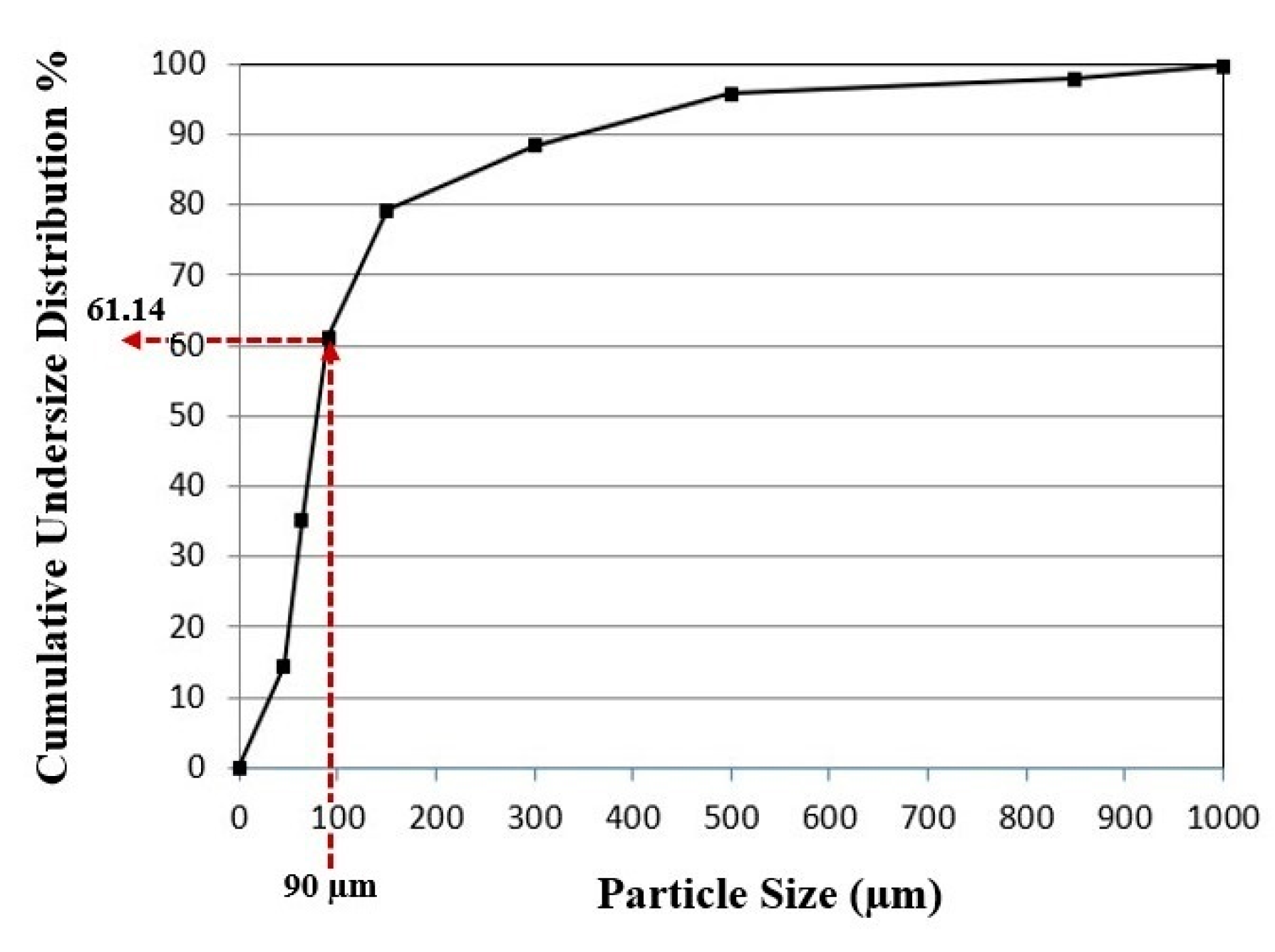
In the M16 measurement, the pulverized coal sample taken from the pipe was sieved using screens determined according to the Tyler sieve series. The weight percentages and the cumulative undersize and oversize values of the pulverized coal for each sieve fraction are presented in
Table 5.
The curve shown in
Figure 7 was plotted using the cumulative undersize distribution (%) values and particle size data from
Table 5.
When the curve in
Figure 7 is examined, it is observed that the amount of pulverized coal with a particle size below 90 µm is 61.14%. According to the boiler design specifications of Soma A Power Plant, 55% of the pulverized coal exiting the pulverizer is required to have a particle size smaller than 90 µm. As part of this study, the renewal of the pulverizer rotors and the replacement of the internal liners have led to a slight improvement in grinding efficiency.
The coal–air mixture, entering the burner at a speed of 20–22 m/s, is directed into two separate channels by a damper that can be adjusted to different angles. The burner’s internal structure is designed to support a three-stage coal ignition process. In the first stage, a portion of the total coal and airflow is ignited by plasma. The air–coal mixture supplied to the second and third stages of the burner is subsequently ignited by the stable flame generated through plasma-assisted ignition in the initial stage. Tests conducted at different damper angles revealed that the most efficient combustion occurs when the damper is set to 25°. In this case, 22% of the coal-air mixture is burned in the plasma flame, while the remaining 78% is ignited within the flame generated by the coal burned in the plasma flame, causing the flame to extend outward from the burner. When the amount of coal fed to the burner reaches 3000 kg/h, 650 kg/h of coal (3000 kg/h × 0.22) is carried with the air and burned within the plasma flame. As the coal feed rate to the burner reaches 3000 kg/h, the magnetron consumes 37.5 kWh of energy. The specific microwave consumption per kilogram of coal is calculated as Q = 37.5 kWh/(3000 kg/h × 0.22) = 0.055 kWh/kg. In a laboratory-scale microwave-assisted burner with an output power of 4.5 kW, the specific microwave consumption per unit of coal was determined to be 0.08 kWh/kg [
6]. As can be observed, this ratio decreases as the system scale increases.
The flame resulting from the interaction of coal with plasma shows a cylindrical form extending along the burner axis. Typically, at a distance of about 15 cm from the end of the coaxial line, there is a bright luminous formation—the plasma flame—with a diameter of approximately 20–25 cm, resulting from the microwave energy converting the air into plasma.
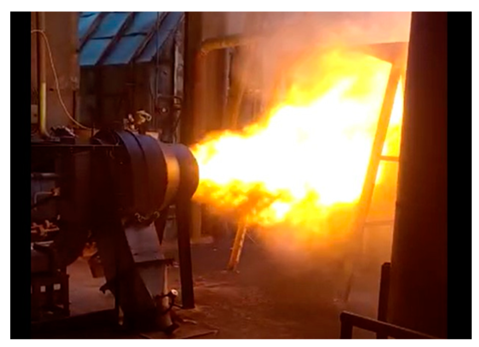
Primary and secondary air flow rates control the plasma flame position. After the plasma flame interacts with the coal, a temperature value of 1200 to 1350 °C is measured using the pyrometer mounted on the burner, as shown in
Figure 1. As the coal feed rate increases, the length of the flame gradually increases. When the coal feed rate reaches approximately 3000 kg/h, the flame length can extend up to 4 m.
Figure 8 shows a photograph of the flame extending from the burner.
The results obtained show that, compared to conventional burners, in a microwave burner, the coal powder and air mixture ignites early and reliably within the plasma flame even at quite low temperatures, around 30 °C, and a stable flame is formed.
The process of igniting and burning pulverized coal within the plasma created by microwaves is similar to the process in the plasma formed by direct current and alternating current electric arcs. First, when coal particles are exposed to the high temperature of the plasma flame, they disintegrate into very small pieces due to thermal shock. This leads to a significant increase in the total surface area of the coal particles and results in the release of a greater amount of volatile matter. Secondly, the electrons and ions present in the plasma environment intensify the chemical reactions of coal oxidation. In the case of microwave plasma, these processes are enhanced due to the plasma being highly unstable and the electron temperature being as high as 11,600 K [
24].
Experiments have shown that the coal–air mixture fed into the burner can easily ignite within the plasma formed by converting secondary air into plasma with microwave energy. In this case, a stable flame of plasma and burning coal particles emerges almost instantaneously.
Assessing the economics of using plasma in a commercial process is challenging. However, the main costs include capital equipment (CAPEX), operational expenditure (OPEX), and utilities. In terms of cost, magnetron-based plasma equipment (generator + impedance matching) operating at frequencies of 2.45 GHz or 915 MHz can be obtained at comparable prices per watt, typically ranging from 1 to 3 Euros/Watt, depending on the type of power supply and the complexity of the impedance matching/tuning systems [
25].
The total cost of the newly developed microwave-assisted auxiliary burner, including capital equipment (CAPEX), operational expenditure (OPEX), and utilities, for a 75 kW system is estimated to be around 180,000 Euros, which falls within the typical range of 1 to 3 Euros/Watt for magnetron-based plasma systems.
On the other hand, it is stated that in a boiler producing 75 tons per hour of steam, approximately 6 tons of fuel oil is consumed during boiler start-up [
10]. This amount corresponds to the minimum of about 15% of the total fuel oil consumption used when auxiliary burners are activated to maintain a stable amount of process steam production in case of a malfunction or a change in coal properties.
The tests of the newly developed auxiliary burner were conducted in a pulverized coal-fired boiler with an electricity generation capacity of 22 MWe, producing 96 tons of steam per hour. Each start-up of this boiler requires approximately 8 tons of fuel oil. According to 2025 data, the price of fuel oil is 740 Euros per ton, resulting in a fuel cost of 5920 Euros for each start-up. When an additional 10% is considered for operational expenses, the total cost of a boiler start-up reaches 6512 Euros.
For this boiler, which is started up approximately 20 times per year, the annual start-up cost amounts to around 130,000 Euros. In addition, based on the last 10 years of operational data, the average annual fuel-oil cost attributed to burners used for flame stabilization during operation, due to equipment failures and variations in coal properties, is estimated at 200,000 Euros. Consequently, the total annual fuel-oil expenditure reaches approximately 330,000 Euros.
It is estimated that four of the newly developed microwave-assisted auxiliary burners would be sufficient to start up the boiler. The total cost of this system is calculated to be 720,000 Euros, with a projected payback period of approximately 26 months. In comparison, when the same application is implemented using arc plasma technology, the payback period is found to range between 16 and 24 months [
17,
26]. Moreover, the magnetron head within the microwave generator has an operational lifespan of approximately 10,000 h [
25], which is significantly longer than the electrodes used in arc plasma burners, typically requiring replacement after only 400–500 h of operation [
18,
27]. This indicates a considerable advantage of the microwave-based technology in terms of durability and maintenance requirements.
Finally, during the start-up of coal-fired thermal power plant boilers, auxiliary equipment such as flue gas treatment systems and electrostatic precipitators are by-passed until coal ignition begins in the boiler, to prevent any damage from the smoke generated by fuels like fuel oil. With the newly developed microwave-assisted auxiliary burner, coal will burn efficiently within a stable plasma flame, ensuring that the flue gas treatment systems and electrostatic precipitators will be operational from the start-up of the boiler. This will minimize environmental impact and allow the electricity generation process to begin smoothly.


