Article

PDDL Task Planning for Tunnel Spraying Based on a Multivariate Coating Accumulation Model

1
School of Mechatronics Engineering, Henan University of Science and Technology, Luoyang 471003, China
2
Collaborative Innovation Center of Machinery Equipment Advanced Manufacturing of Henan Province, Luoyang 471003, China
3
Key Laboratory of Mechanical Design and Transmission System of Henan Province, Luoyang 471003, China
4
Longmen Laboratory, Luoyang 471003, China
5
Zhongshan Polytechnic Mechanical and Electrical Engineering College No. 25, Boai 7 Road, Zhongshan 528400, China
*
Author to whom correspondence should be addressed.
Appl. Sci. 2025, 15(9), 5187; https://doi.org/10.3390/app15095187
Submission received: 24 February 2025 / Revised: 1 May 2025 / Accepted: 2 May 2025 / Published: 7 May 2025

Abstract

:
To address the challenges of low automation in tunnel wet-spraying jumbos and the heavy reliance on manual expertise for ensuring the spraying quality, this study proposes a novel task planning method for tunnel spraying operations. First, the tunnel surface to be sprayed is aligned with the designed contour using a vehicle navigation method, enabling the estimation of the overbreak and underbreak volumes. These volumes are then utilized to hierarchically plan the spraying tasks (e.g., patching, filling, and surface smoothing). A concrete coating thickness prediction method is developed, incorporating static and dynamic coating accumulation models with key process parameters—spraying flow rate Q, air pressure P, and spraying distance H—as independent variables. Based on the required thickness for each task layer, operational parameters such as the spraying duration t and nozzle movement speed v are optimized. By analyzing the spray gun action combinations and integrating hierarchical task planning with parameter optimization, a Planning Domain Definition Language (PDDL) domain file and problem file are designed to generate the spray gun action sequences and paths via a planner. The experimental results demonstrate that the overbreak volume on the sprayed tunnel surface is reduced to approximately 3 cm after applying the planned sequences. The proposed method autonomously generates the task hierarchies and the corresponding spray gun actions based on the 3D morphology of the tunnel surface, effectively ensuring the spraying quality while significantly reducing the dependence on manual intervention. This approach provides a practical solution for enhancing automation and precision in tunnel spraying operations.

1. Introduction

Currently, the initial support for tunnels constructed by the blasting and excavation method mainly relies on manually operated wet-spray platforms for concrete spraying. However, long-term practice has shown that, due to the complex surrounding rock conditions and limitations of construction technology, the concrete spraying process often depends excessively on the operator’s experience. This not only increases construction costs but also poses potential risks to both the quality of the project and the health of the workers. Therefore, research on tunnel spraying task planning methods is of great significance for improving construction quality control and promoting the development of automated spraying technology.
Research on tunnel spraying task planning has primarily focused on wet-spray path planning and the development of coating thickness models [1,2,3]. For example, some studies have established a kinematic model of the spray robotic arm based on the three-dimensional profile of the tunnel using robotics methods, and they have designed the corresponding path planning system [4]. Other work has analyzed wet-spray tasks and proposed an automated wet-spray method to generate the three-dimensional operational trajectories [5]. Existing coating thickness models can be roughly divided into unbounded-range models and bounded-range models: unbounded-range models (such as the Gaussian distribution [6] and the Cauchy distribution [7]) are suitable for planar surfaces with relatively low requirements in terms of spray quality, while bounded-range models (such as the β distribution model [8], the elliptical double β distribution model [9], and the parabolic model [10]) are more appropriate for describing spray areas of specific shapes. Research based on the elliptical double β distribution model has constructed a generalized coating thickness model using multiple variable spraying process parameters, achieving the prediction of the cumulative coating thickness under different process conditions [11]. In addition, studies aimed at improving the uniformity of paint film thickness by optimizing the spraying rate, spraying height, and trajectory spacing have also achieved notable results [12]. Similarly, in addressing the issue of uneven spray quality during robotic spray path planning, some researchers have optimized relevant parameters by using the variance between the theoretical and actual values of the paint film thickness as the objective function, thereby enhancing the spray quality [13]. Furthermore, work on the influence of the acceleration and deceleration zones on the paint film thickness uniformity has achieved optimal uniformity through adjustments to the spraying speed and spacing [14].
In recent years, with the rapid development of intelligent planning technology, new approaches have emerged for planning tunnel spraying tasks and autonomously generating action sequences [15]. Early modeling methods for intelligent planning include the STRIPS (Stanford Research Institute Problem Solver) method [16], the Hierarchical Task Network (HTN) planning method [17], and the Planning Domain Definition Language (PDDL) method [18]. Among these, the STRIPS method is only applicable to idealized task scenarios, while the HTN method requires separate handling of spatial constraints, temporal reasoning, and motion control dimensions. In contrast, the PDDL method has been widely adopted due to its comprehensive modeling capabilities. Previous studies have expanded the definitions of resources and activity instances based on the PDDL, covering the duration and effect attributes of activities, thereby improving the descriptive accuracy [19]. Other research has employed the PDDL for domain modeling and proposed a generic hierarchical task planning software architecture, further demonstrating its advantages in solving complex planning problems [20]. Through the PDDL task planning method, tunnel wet-spray tasks can be abstracted into formal descriptions, effectively decoupling domain knowledge from specific problem-solving and generating reasonable action sequences.
The current tunnel spraying task planning methods primarily focus on wet-spray path planning and trajectory planning. However, these approaches cannot directly guide robotic arm operations, as the spraying quality remains dependent on worker expertise. Moreover, they require re-planning for different tunnel environments, lacking generalizability. The PDDL task planning method can decompose complex tunnel spraying tasks directly into executable action sequences for wet-spray robotic arms, thereby replacing manual decision-making processes. This significantly reduces the reliance on human experience for ensuring the spraying quality. Additionally, multiple PDDL problem files can share the same PDDL domain file. When faced with different tunnel environments, only minor modifications to the problem file are needed for modeling and solving, endowing this method with notable versatility.
This paper proposes a tunnel spraying PDDL task planning method integrated with a coating accumulation model. The approach first estimates the tunnel overbreak and underbreak quantities using vehicle localization techniques, then it divides the spraying tasks into hierarchical levels. Subsequently, it performs parameter planning for each task level based on established static and dynamic concrete coating accumulation models, achieving dwell time calculation at the spraying points and end-effector speed determination for mobile spraying operations. Finally, the PDDL task planning method is implemented by constructing PDDL files that integrate task hierarchy planning with parameter optimization, generating executable spraying action sequences. Experimental validations demonstrate the rationality of the derived spraying operation sequences.
The organization of this paper is as follows.Section 2 details the hierarchical planning method for spraying tasks, the construction of a multivariate spraying model, and the PDDL based task planning approach for tunnels. Section 3 experimentally validates the effectiveness of the PDDL generated action sequences in controlling tunnel over-excavation. Section 4 summarizes the key findings of this study and proposes future research directions.

2. Methods

2.1. Hierarchical Planning of Spraying Tasks Based on over- and Under-Excavation Volume

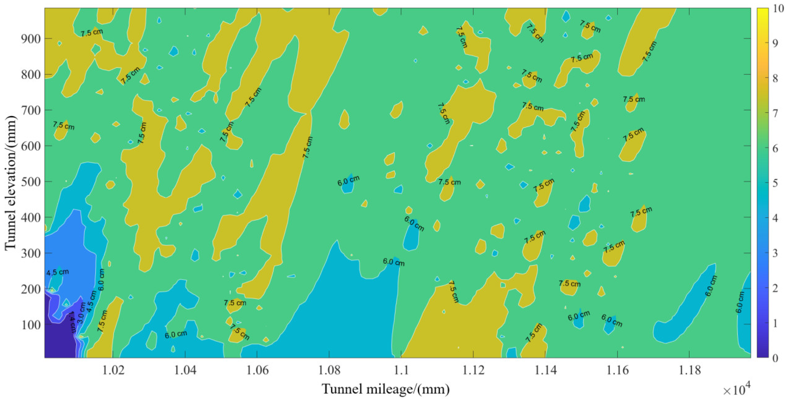
2.1.1. Estimation of Over-Excavation and Under-Excavation

The estimation of over- and under-excavation at the tunnel blasting face forms the basis for the hierarchical planning of spraying tasks. Typically, a vehicle-mounted laser scanner is used to scan the tunnel working face. The obtained point cloud data are then aligned to the tunnel coordinate system and compared with the tunnel design profile to estimate the over- and under-excavation of the current working face.
If the pose of the wet spraying vehicle body coordinate system, denoted as {O}, in the tunnel coordinate system {G} is known T O G , the point cloud alignment process is as follows:
W G = i T O G W O ( i i = 1 , , n )
Here, W i O represents the vehicle body coordinates of the scanned point cloud, and W i O represents the transformed tunnel coordinates of the scanned point cloud. The point cloud data undergo slicing and projection processing to obtain the actual contour line C a c t u a l G of the tunnel blasting surface. By comparing this with the tunnel design contour line C d e s i g n G , the over-excavation and under-excavation amounts at various points on the tunnel wall, denoted as Δ i , can be determined.
Δ i = C G ( G a c t u a l , i W i ) G C d e s i g n , i ( i = 1 , , n )
Thus, determining the pose T O G of the wet spraying vehicle inside the tunnel is key to estimating the over-excavation and under-excavation amounts. An inclinometer is installed on the vehicle body to measure the lateral tilt angle α and the forward tilt angle β. Two calibration points W 1 and W 2 are fixed on the vehicle body to calculate the horizontal rotation angle γ of the vehicle body, as shown in Figure 1.
The coordinate system of the inclinometer is taken as the vehicle body coordinate system {O}, with the coordinates of calibration points W 1 and W 2 in the vehicle body coordinate system {O} denoted as W 1 O , W 2 O , W 1 O , and W 2 O , and the coordinates in the tunnel coordinate system {G} denoted as W 1 G and W 2 G . The vector formed by two points in the {O} coordinate system is denoted as m , and the vector in the {G} coordinate system is denoted as n , that is,
m = ( m x , m y , m z ) = W O 1 W 2 O W O 1 W 2 O
n = ( n x , n y , n z ) = W G 1 W 2 G W G 1 W 2 G
The deviation angle between the vectors m and n in the XOY plane is the horizontal rotation angle of the vehicle, denoted as γ .
cos γ = m x n x + m y n y ( m x 2 + m y 2 ) ( n x 2 + n y 2 )
According to the relationship between the rotation matrix R O G and the Euler angles, we have:
R O G = cos α cos β cos α sin β sin γ - sin α cos γ cos α sin β + sin α sin γ   sin α cos β sin α sin β sin γ + cos α cos γ sin α sin β cos γ - sin γ   sin β cos β sin γ cos β cos γ  
t O G = W G R O G W O
T O G = R O G t O G 0   1

2.1.2. Spraying Task Hierarchical Planning

Based on the analysis of the over-excavation and under-excavation, the maximum blast face profile, blast face profile, and average blast face profile of the actual tunnel contour are determined. Combined with the tunnel design contour and the arch profile, the tunnel spraying layers are divided into the pit-filling layer, filling layer, and sweeping layer, with their respective thicknesses denoted as δ1, δ2, and δ3. Rg, Rb, Rj, and Rd represent the arch profile radius, blast face profile radius, average blast face profile radius, and design profile radius, respectively. Δ is the distance between the blast face profile and the design profile, as shown in Figure 2.
The pit-filling layer is the region between the maximum blast surface contour and the average blast surface contour. The pit-filling task involves determining the locations of the pits and their opening radii, which are then used to plan the positions of the stopping points and the spraying distance H1. The filling layer is the region between the average blast surface contour and the arch contour. In this layer, the grid stopping points are planned. The grid spacing is determined using the optimal trajectory spacing model, and the spraying distance H2 is determined based on manual experience. The sweeping layer is the region between the arch contour and the design contour. For this layer, the endpoints of the spraying path are planned, the spraying distance H3 is determined based on manual experience, and the spray gun movement speed is calculated using the dynamic spraying model.
To determine the spraying thickness of each task layer, it is necessary to adaptively select a reasonable average blast surface contour based on the actual blasting conditions. The radius Rj of the average blast surface contour is defined as the mean value of the distances from various points on the tunnel blast surface contour to the center of the design contour, which can be expressed as:
R j = 1 π π 2 π 2 R b d ω
Thus, the intersection points A 2 i 1 and A 2 i between the average blast face profile and the blast face profile can be obtained, and the distance between the two points is the opening radius S A 2 i 1 , A 2 i of the deep pit., where i 1 .
According to the adaptively selected average blast face profile radius Rj, let the thickness to be sprayed for the pit-filling layer be T1, for the filling layer be T2, and for the sweeping layer be T3. The thickness to be sprayed for each layer can be calculated as follows:
T 1 = Δ ( δ 2 + δ 3 ) , Δ > δ 2 + δ 3 0 , Δ δ 2 + δ 3
T 2 = δ 2 , δ 2 + δ 3 < Δ Δ δ 3 , δ 3 < Δ < δ 2 + δ 3 0 , Δ < δ 3
T 3 = δ 3 , Δ > δ 3 Δ , 0 < Δ < δ 3 0 , Δ < 0

2.2. Operation Parameter Planning Based on Multi-Variable Spraying Layer Accumulation Model

2.2.1. Multi-Variable Spraying Layer Accumulation Model

In spraying operations, the process typically involves fixed-point spraying or continuous linearly moving spraying, requiring the establishment of a spraying process parameter model based on the static and dynamic spraying layer accumulation models.
When the spray nozzle is stationary relative to the work surface, maintaining a steady flow rate Q and air pressure P, the concrete particles attach to the wall surface, forming a circular area with a spraying radius R. The maximum accumulation thickness dmax occurs in the circular area, as shown in Figure 3.
The coating thickness on the conical diameter section follows a beta distribution model, meaning that the cumulative thickness D(r) at a distance rrr from the circle center O satisfies:
D ( r ) = d max ( 1 r 2 R 2 ) β 1
where β is an empirical value determined by the operating parameters during spraying (which can be obtained through empirical formulas or experimental fitting), and the volume of the cone is:
V = 0 R D ( r ) 2 π r d r
If the sprayed volume after continuously spraying for time t at a spraying flow rate Q (the volume of concrete sprayed) is:
V = Q t
By combining Equations (13)–(15), the maximum cumulative thickness dmax after continuous spraying is:
d max = Q t β π R 2
From the geometric relationship in Figure (3), the relationship between the spray radius R, the spraying distance H, and the spray angle φ is:
R = H tan φ
According to reference [11], the relationship between the spray angle φ , spray flow rate Q, and air pressure P is:
tan φ = K Q a 1 P a 2
The parameters K, a1, and a2 are experimental fitting parameters. Thus, by solving the system of Equations (13), (16)–(18), a static spraying model related to the spray flow rate Q, injection pressure P, injection distance H, and spraying time t can be established as follows:
D ( r ) = Q 1 2 a 1 t β π K 2 H 2 P 2 a 2 ( 1 r 2 K 2 H 2 Q 2 a 1 P 2 a 2 ) β 1
When the spray gun moves perpendicularly to the work surface at distance H, maintaining a linear velocity v with flow rate Q and air pressure P, concrete particles adhere to the rock surface, forming a rectangular area with a thicker middle and thinner edges. The spray width radius (half-width) is R, and the maximum accumulated thickness is dmax, as shown in Figure 4.
Assuming that the accumulated thickness distribution in the direction perpendicular to the spray direction still follows the beta distribution described by Equation (13), the accumulated coating thickness D(x0) at a point A, located at a distance x0 from the centerline of the spray operation, satisfies:
D ( x 0 ) = 0 t 0 d max ( 1 r 2 R 2 ) β 1 d t
The equation t 0 = 2 R 2 x 0 2 / v represents the duration during which point A is covered by the spray during the operation, i.e., the time it takes for point A to enter and leave the spray area (assuming point A enters the spray area at t = 0s). r = ( R 2 x 0 2 v t ) 2 + x 0 2 represents the distance between point A and the spray center at time t. Equation (16) expresses the accumulated thickness at point A as the result of integration over time during the spray operation. Substituting dmax into the equation, a dynamic spraying model related to spray flow rate Q, injection pressure P, spray distance H, and spraying speed v can be established:
D ( x 0 ) = Q 1 a 1 β 2 K π v H P a 2 ( 1 x 0 2 K 2 H 2 Q 2 a 1 P 2 a 2 ) β 1

2.2.2. Task Layer Parameter Planning

The spray distance H for the pit-filling layer is the distance from the nozzle of the spray gun to the tunnel surface. To ensure the density and quality of the sprayed concrete, engineering experience suggests selecting H ≈ 1.5 m.
For the pit-filling layer, the positions of the pits are determined based on an even distribution of explosion-fragmented rock surfaces, treating individual pits or connected pits as independent. The selection of operating points for spraying is related to the size of the pit openings.
When the distance H1 between the spray gun and the pit meets the static spray conditions, the approximate spray coverage radius is R = H 1 K Q a 1 P a 2 . For pits with an opening radius S A 1 , A 2 / 2 smaller than the spray coverage radius R, the operating point is selected as the position directly above the center of the largest superimposed pit. This is marked as U1 (X,Y,Z), and its coordinates are determined as shown in the figure. If the opening radius of a pit S A 1 , A 2 / 2 is greater than the spray coverage radius R, the connected region E of the pit will require multiple operating points (U1, U2, , Ui) within E to ensure full coverage of the spray area, as shown in Figure 5. If any operating point U i + 1 E , the selection of operating points for the pit-filling layer will stop.
The station point is the position of the spray gun during the spraying task, aligned with the normal direction of the operating point Vi. Its coordinates V(X,Y,Z) are determined based on the spray distance H1, the over-excavation amount Δ at the operating point, the spray angle   θ , and the coordinates of the operating point, as shown in Figure 6. Thus, the spray angle θ is the angle between the normal direction of the station point and the Y-axis of the tunnel coordinate system, where:
cos θ = U y U y 2 + U z 2
sin θ = U z U y 2 + U z 2
The station point and the operating point lie in the YOZ plane, so the X-coordinate of the station point is the same as the X-coordinate of the operating point. The coordinates of the station point V(X,Y,Z) are calculated as follows:
V i = U i H 1 0 cos θ sin θ
Based on the static spraying model, the station spraying time t for the pit-filling layer with the planned spraying thickness T 1 is calculated as:
t = π K 2 T 1 H 1 P 2 a 2 2 Q 1 2 a 1 β
The spray distance H2 for the filling layer refers to the distance from the nozzle of the spray gun to the designed contour. To ensure the density and quality of the sprayed concrete, the spray distance H2 is selected as 1.5 m based on manual experience.
To ensure the surface flatness of the coating, it is necessary to control the grid spacing L between adjacent grids such that the difference between the maximum accumulated thickness dL/2 in the overlapping region of two adjacent trajectory cross-sections and the maximum thickness dmax in a single trajectory cross-section is minimized., as shown in Figure 7.
The accumulated thickness in the overlapping region of adjacent trajectories can be modeled as the superposition of the accumulated thickness contributions from both individual trajectories within the overlapping area. Therefore, the maximum accumulated thickness in the overlapping region can be calculated from Equation (13) as follows:
d L / 2 = 2 t d max ( 1 L 2 4 R 2 ) β 1
Similarly, according to Equation (13), the maximum accumulated thickness at the center of a single trajectory is calculated as follows:
D r = 0 = t d max
By combining Equations (17), (18), (26) and (27), the calculation of the optimal spacing L between adjacent trajectories is derived as follows:
L = 2 R ( 1 2 1 1 β ) 1 2 = 2 H K Q a 1 P a 2 ( 1 2 1 1 β ) 1 2
The first operating point of the filling layer is selected at the sidewall positions on both sides of the tunnel, with its coordinates U(X,Y,Z) obtained through vehicle-mounted radar scanning. Using Equations (24)–(26), the coordinates of the first grid station point in the tunnel coordinate system {G} are calculated as V11(X1,Y1,Z1). The positions of the adjacent grid station points are distributed as shown in Figure 8.
Calculation of the coordinates for adjacent stopping points V1,j in the filling layer:
V i , j = V 1 , 1 + ( i 1 ) L Y 1 2 + Z 1 2 cos ( θ 1 + ( j 1 ) Δ θ ) Y 1 2 + Z 1 2 sin ( θ 1 + ( j 1 ) Δ θ )
Δ θ is the angle between adjacent stopping points in the tunnel’s circumferential direction.
Δ θ = L Y 1 2 + Z 1 2
According to the static spraying model, the spraying time t at a stopping point is determined by the different spraying thickness T2 at that point.
t ( Q , P , H 2 , T 2 ) = π K 2 T 2 H 2 P 2 a 2 2 Q 1 2 a 1 β
The spraying distance H3 for the sweeping layer refers to the distance from the nozzle tip to the design contour. To ensure the compaction and spraying quality of the sprayed concrete, H3 is selected as 2 m based on manual experience.
The first operational endpoint of the sweeping layer is selected in the region with the extreme mileage of the tunnel to be sprayed. The height from the ground is determined by the safe distance maintained between the spray gun and the tunnel floor. Its coordinates U(X,Y,Z) are obtained via vehicle-mounted radar scanning. The first spray gun motion path endpoint V11(X,Y,Z) is calculated using Formula (25). Let the difference in the extreme mileage of the tunnel’s spraying region be B, as shown in Figure 9. The coordinates of the spray gun motion path endpoint are calculated as follows:
V i , j = V 1 , 1 + ( i 1 ) B Y 1 2 + Z 1 2 cos ( θ 1 + ( j 1 ) Δ θ ) Y 1 2 + Z 1 2 sin ( θ 1 + ( j 1 ) Δ θ )
According to the dynamic spraying model, during sweeping operations, the spraying speed v along the sweeping path is calculated based on the spraying thickness T3 of the sweeping layer:
v ( Q , P , H 3 , T 3 ) = Q 1 a 1 β 2 K π T 3 H 3 P a 2

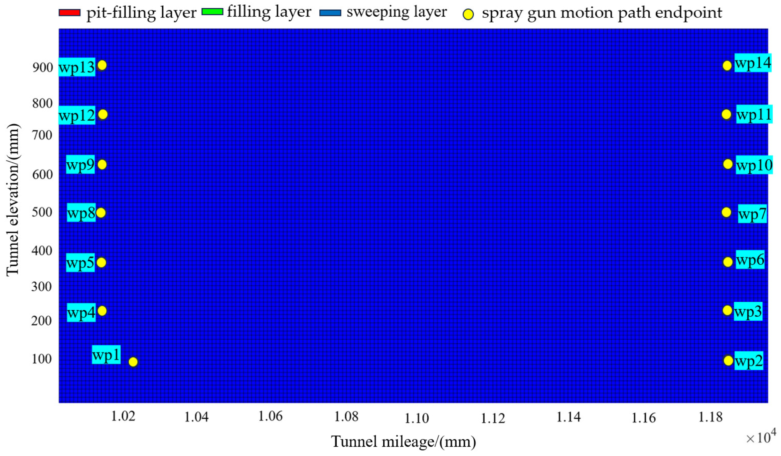
2.3. Spray Gun Action Sequence Planning

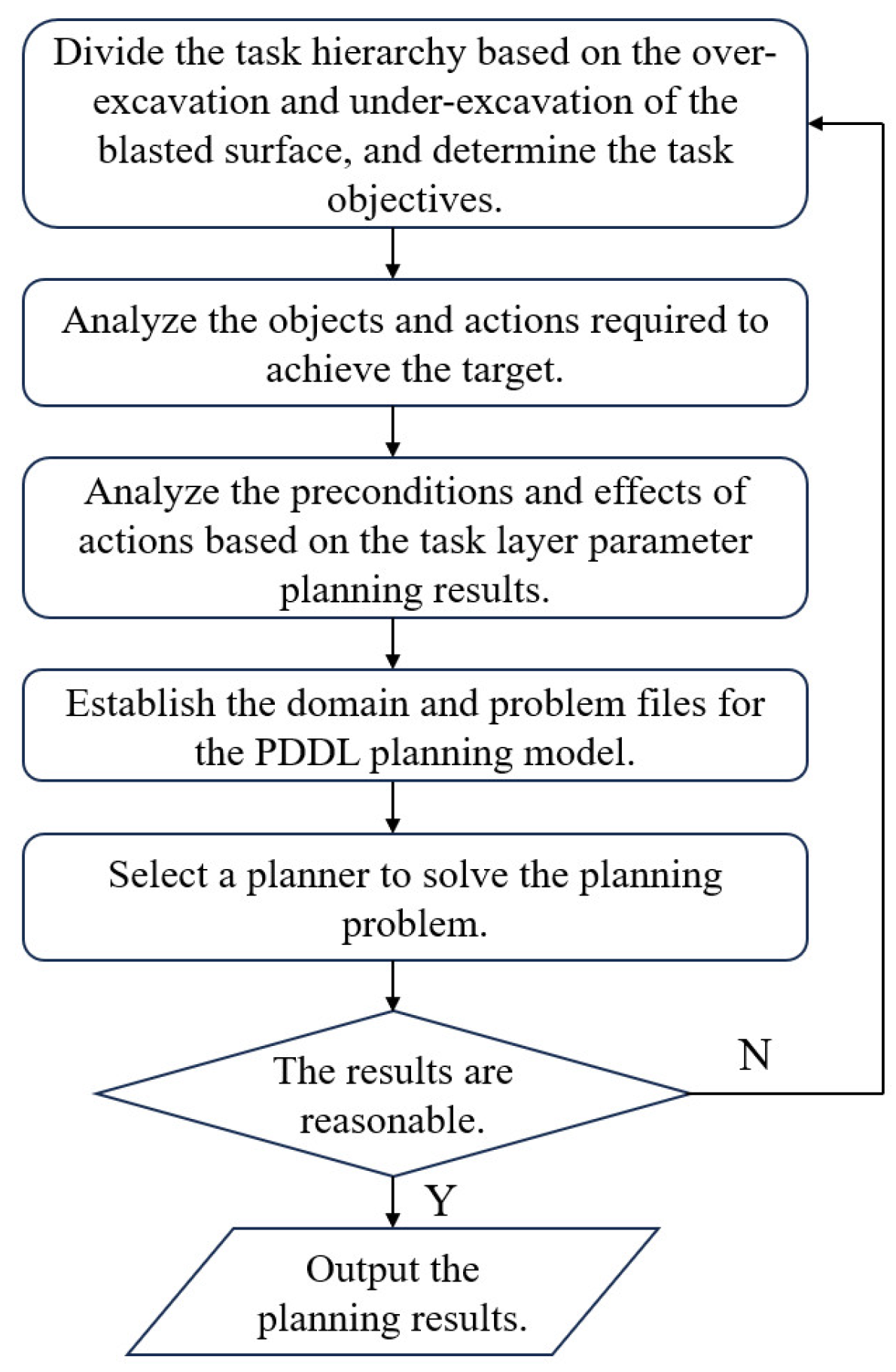
2.3.1. Tunnel Spraying Task Modeling Process

This paper is based on task-level planning, where the spraying task objectives are defined. From this, the spraying objects and actions are analyzed. With the operational parameter planning results as constraints, the preconditions and post-effects of actions are examined. Subsequently, a domain file (domain.pddl) and a problem file (problem.pddl) for the spraying task are established. Based on this, a PDDL-based tunnel spraying task planning model is created. The planner’s output is then used to generate the planning results. The modeling process is shown in Figure 10.

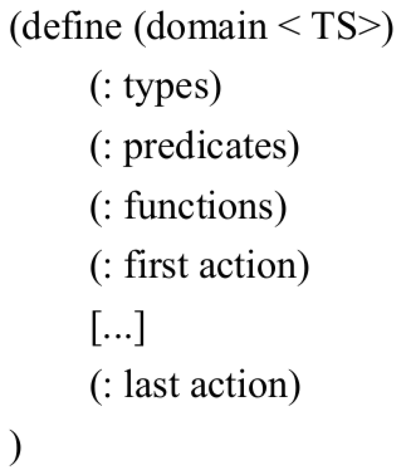
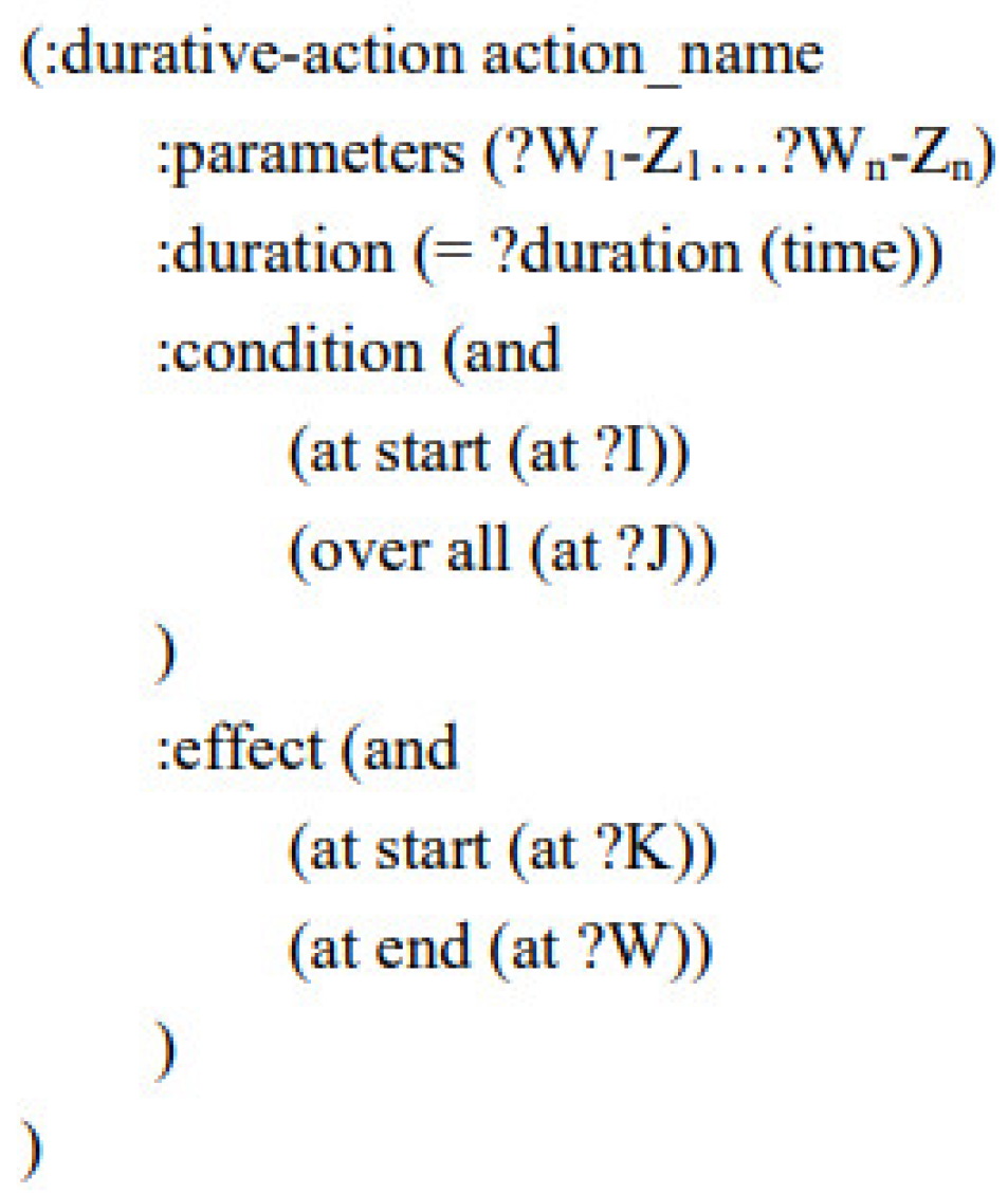
2.3.2. Domain File Creation

The PDDL domain file (domain.pddl) for tunnel spraying tasks describes the domain knowledge of the spraying task. It uses states and actions to model the tunnel spraying task. The state is mainly represented by types, predicates, and functions, while actions are described through preconditions, add effects, and delete effects.
Actions are executed to change the state. The structure is shown in Figure 11. The relevant content definitions in the tunnel spraying PDDL domain file are shown in Table 1.
In the types section, the layers are divided into the patching layer (patching), filling layer (fill), and sweeping layer (surface). The stopping points for the patching layer, the grid stopping points for the filling layer, and the spray gun motion endpoints for the sweeping layer are all unified and defined as spray target points (wp). Since continuous straight-line motion (L_motion) and continuous curved motion (C_motion) are required in the sweeping layer, the target points in the sweeping layer are further divided into straight-line motion type (Lm) and curved motion type (Cm) based on these constraints. Additionally, the action executor (robot) is defined.
Predicates mainly describe the state of the spray gun and the target points. For instance, at ?robot indicates the target point where the spray gun is located, next-to ?wp1 ?wp2 denotes that two target points are adjacent, visited ?wp and unvisited ?wp indicate whether a target point has been visited, and is-fill ?wp and is-unfill ?wp indicate whether the target point has been sprayed.
The functions define the distance between adjacent target points (distance ?wp1 ?wp2) the movement speed of the spray gun between target points during patching and filling operations (robot_speed ?robot) and the spraying thickness required at a target point (T ?wp).
The definition of an action includes five components. The action_name refers to the name of the action, while parameters define the parameters associated with the action. Moreover, duration indicates the duration, which can either be a fixed value or a time function that determines the value. Additionally, condition represents the preconditions for the action, and effect describes the results following the execution of the action, as shown in Figure 12.
Since the spraying methods differ between layers, the actions need to be categorized based on the layer. For example, the patching layer actions are move1 and spray1, representing the movement action between patching operation points and the spraying action at stopping points. The filling layer actions are move2 and spray2, representing the movement action between filling operation points and the spraying action at grid stopping points. L_motion and C_motion represent the continuous straight-line spraying action and continuous arc spraying action in the sweeping layer, respectively.
To ensure the correct execution of the actions corresponding to different tasks, the constraints of the target point’s layer and state are pre-built into the parameters and preconditions of the action definitions. These constraints must be satisfied when executing the corresponding actions for each layer.
In the definition of the action duration (duration), the duration for the patching layer target point spraying action (spray1) is defined by Formula (24), the duration for the filling layer target point spraying action (spray2) is defined by Formula (29), and the duration for the sweeping layer continuous spraying actions (L_motion and C_motion) is defined by the distance function (distance) and Formula (31). Figure 13 lists the relevant definitions for the patching task. The logic for the filling and sweeping tasks is similar and will not be elaborated further here.

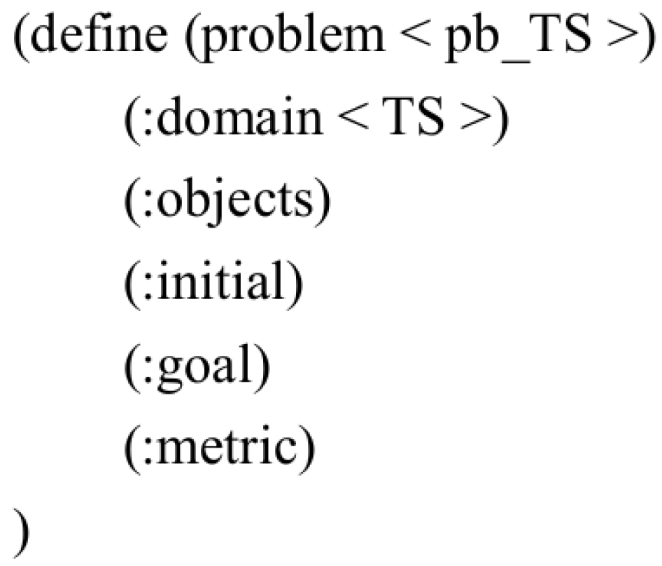
2.3.3. Problem File Creation

The PDDL problem file (problem.pddl) for the tunnel spraying task describes the specific planning problem by defining the objects, initial state, goal state, and optimization metric within the tunnel spraying task, as shown in Figure 14.
The objects in the PDDL problem file for the tunnel spraying task need to define the types of target points planned, such as the stopping points for the tunnel patching layer, the grid stopping points for the filling layer, and the spray gun motion endpoints for the sweeping layer. The initial state (Init) must define the over-excavation amount and state (unvisited, unpainted) for each target point, as well as the adjacency relations between the target points and the specific distances. The goal state (Goal) is that all the operation points are visited and sprayed. The optimization metric is to minimize the time taken to complete the task.
As a modular planning method, the PDDL allows planning problems in the same domain to share a common domain file. Different problem instances only need to define different problem files

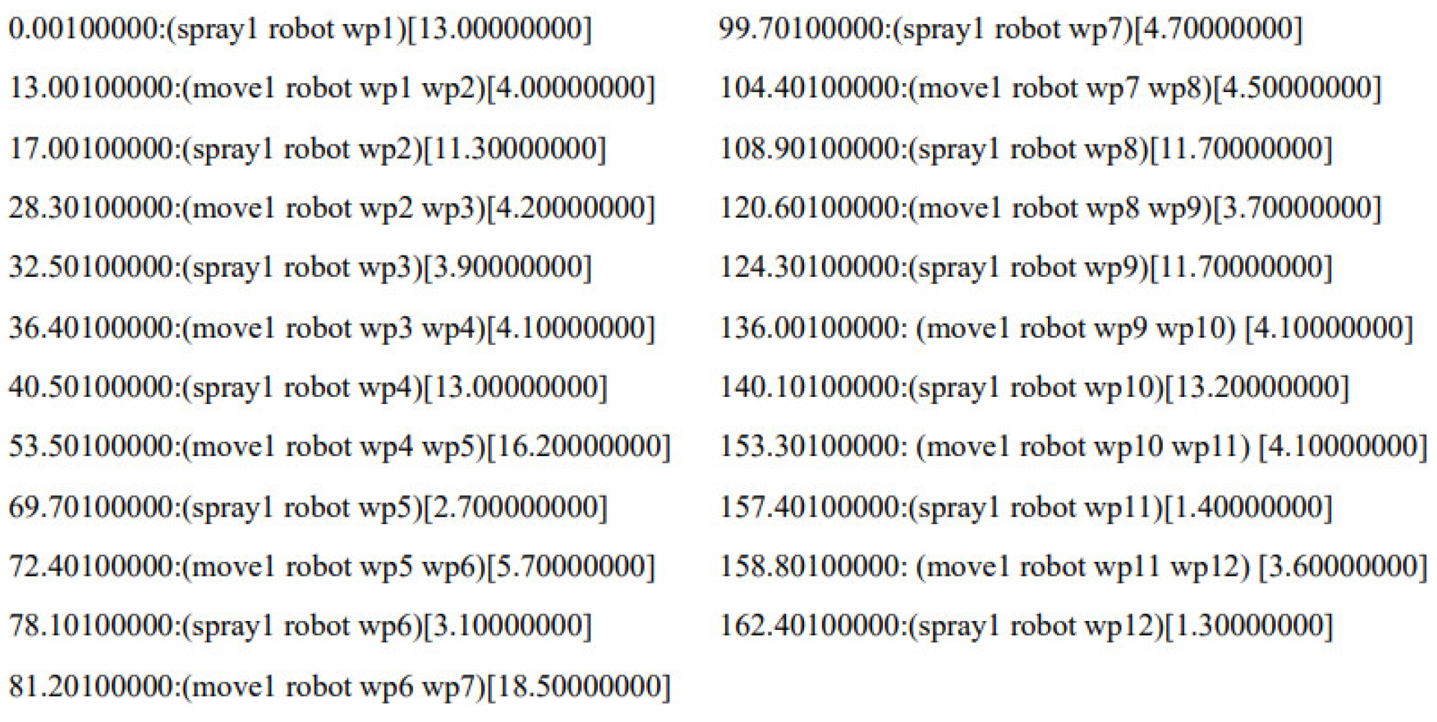
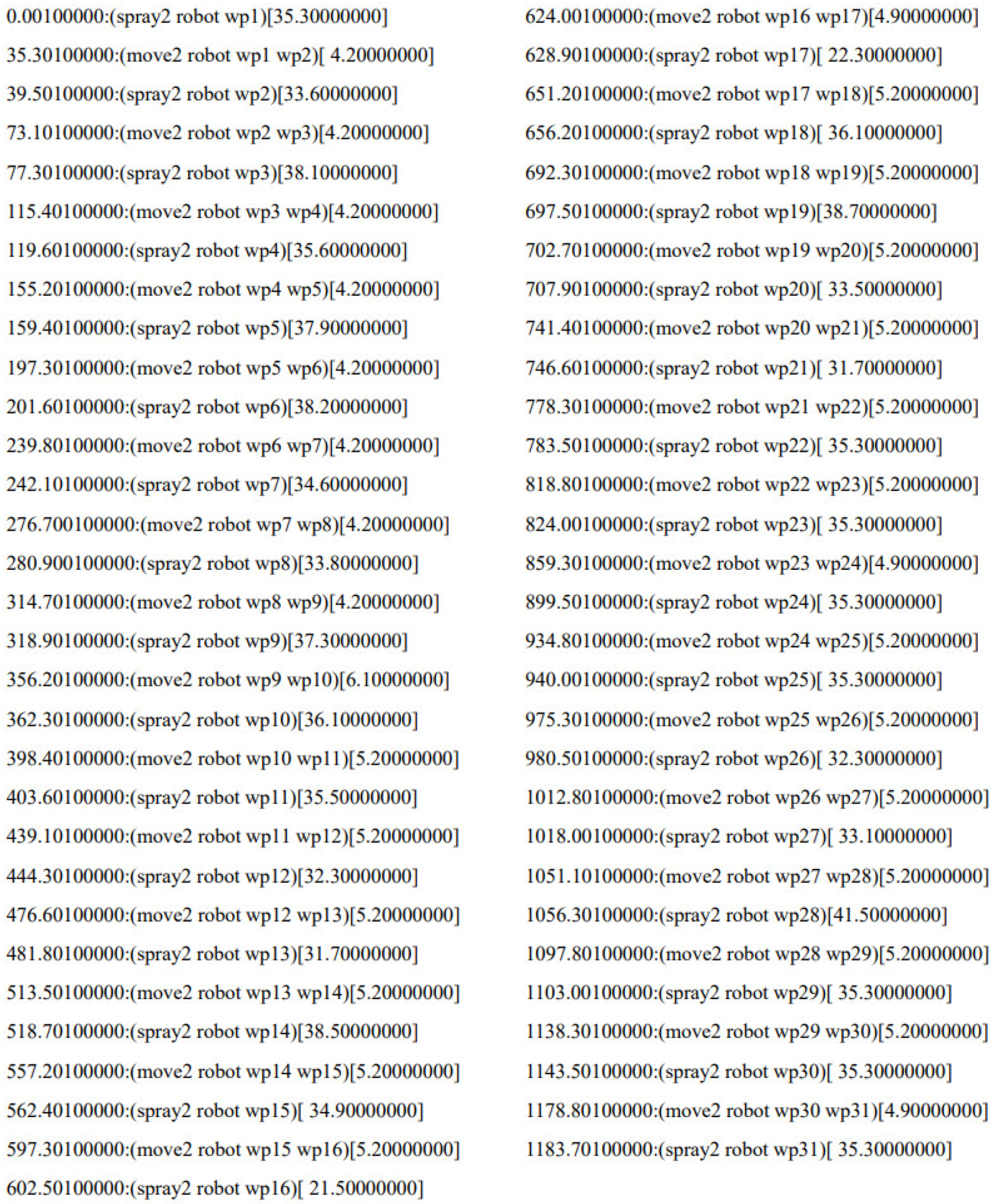
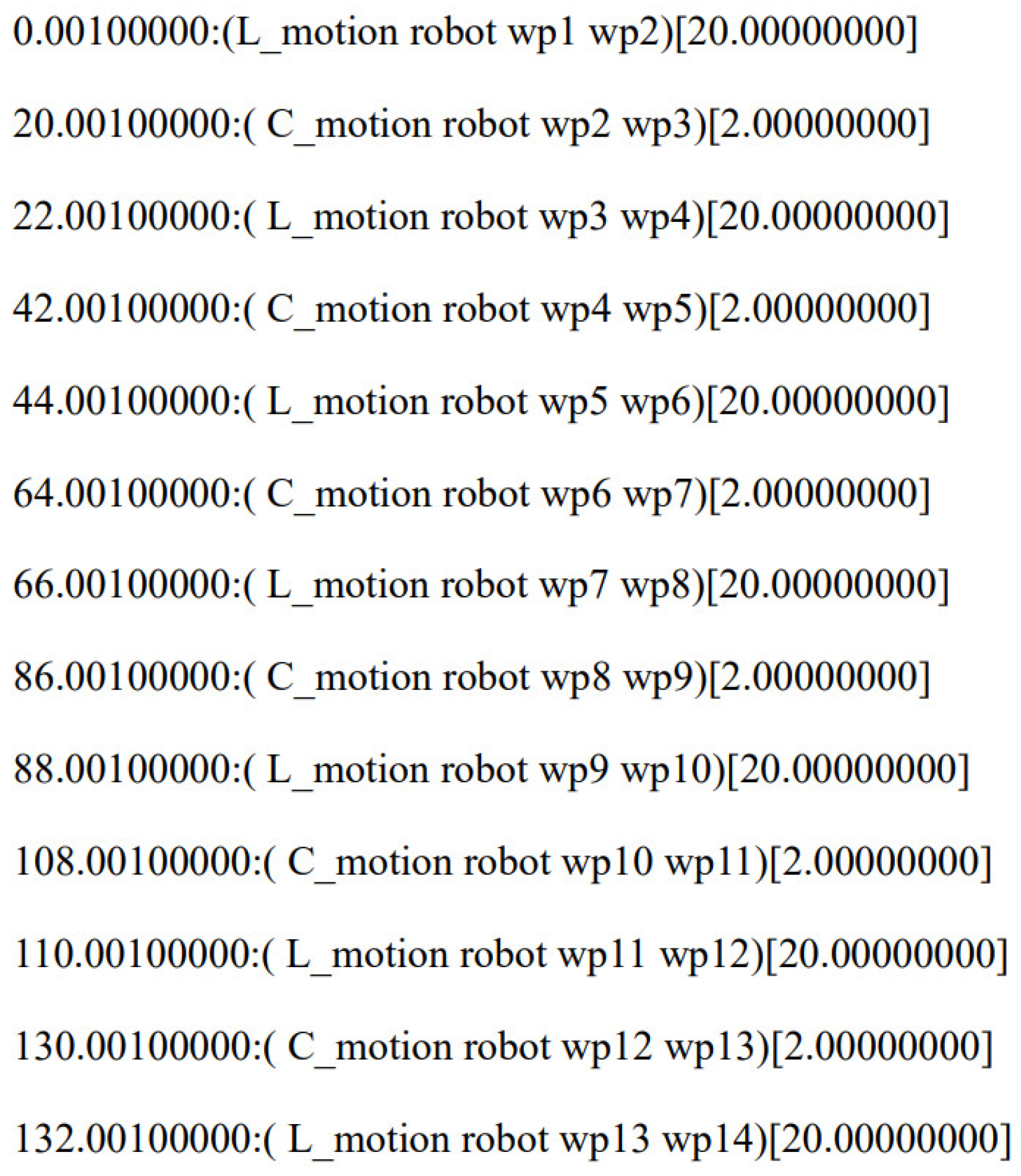
2.3.4. Planning Solution

In order to obtain a reasonable planning result for the tunnel spraying task, the POPF (Partial-Order Planning Forward) planner, which supports temporal features and PDDL 3.1, is chosen for the planning solution. The POPF planner can utilize most of the features of the PDDL.
The POPF planner is based on Partial-Order Planning (POP) and generates a partially ordered execution graph for the task through the state-space search and dynamic selection of actions. This approach allows for the simultaneous execution of multiple tasks, offering efficiency, flexibility, and good scalability. It is well suited for complex task planning problems, particularly in robotics and automation systems. Compared to other common temporal planners such as SAPA (Simultaneous Action and Parameter Adjustment), SGPlan (Stochastic Graph Planner), and LPG (Local search for Planning Graphs), the POPF planner has faster solving speeds and delivers higher-quality solutions for minimizing the makespan. It outperforms SAPA, SGPlan, and LPG in large-scale temporal planning tasks [21].

3. Experiments and Results

3.1. Experimental Steps

Under normal operating conditions, the concrete spraying flow rate of the wet-spray jumbo is approximately 6 m3/h, and the air pressure is approximately 1.2 MPa. The dwell time at the stopping points for the patching layer and filling layer is calculated using Equations (25) and (31), respectively, while the nozzle movement speed for the sweeping layer is determined by Equation (33). The tunnel blasting surface shown in Figure 15 was selected as the target spraying area for the experimental coating process. Based on the over-excavation values of the spraying area, a contour map with an interval of 2 cm is drawn, as shown in Figure 16. The spraying area is divided into a grid, and the over-excavation and under-excavation values for each grid are determined by the average over-excavation value of the point cloud data within that grid. To ensure the accuracy, the grid cell size is set to 1 cm. Based on the over-excavation and under-excavation values of the spraying area, a layer classification is performed. The over-excavation range of 40 cm to 50 cm is designated as the patching layer, 10 cm to 40 cm as the filling layer, and 0 cm to 10 cm as the sweeping layer. The layer classification results are shown in Figure 17.
This paper conducts task planning for each layer and performs tunnel spraying experiments. After spraying, the over-excavation and under-excavation contour map of the tunnel is redrawn to verify the rationality of the spray gun action sequence planned by the PDDL.

3.2. Experimentals

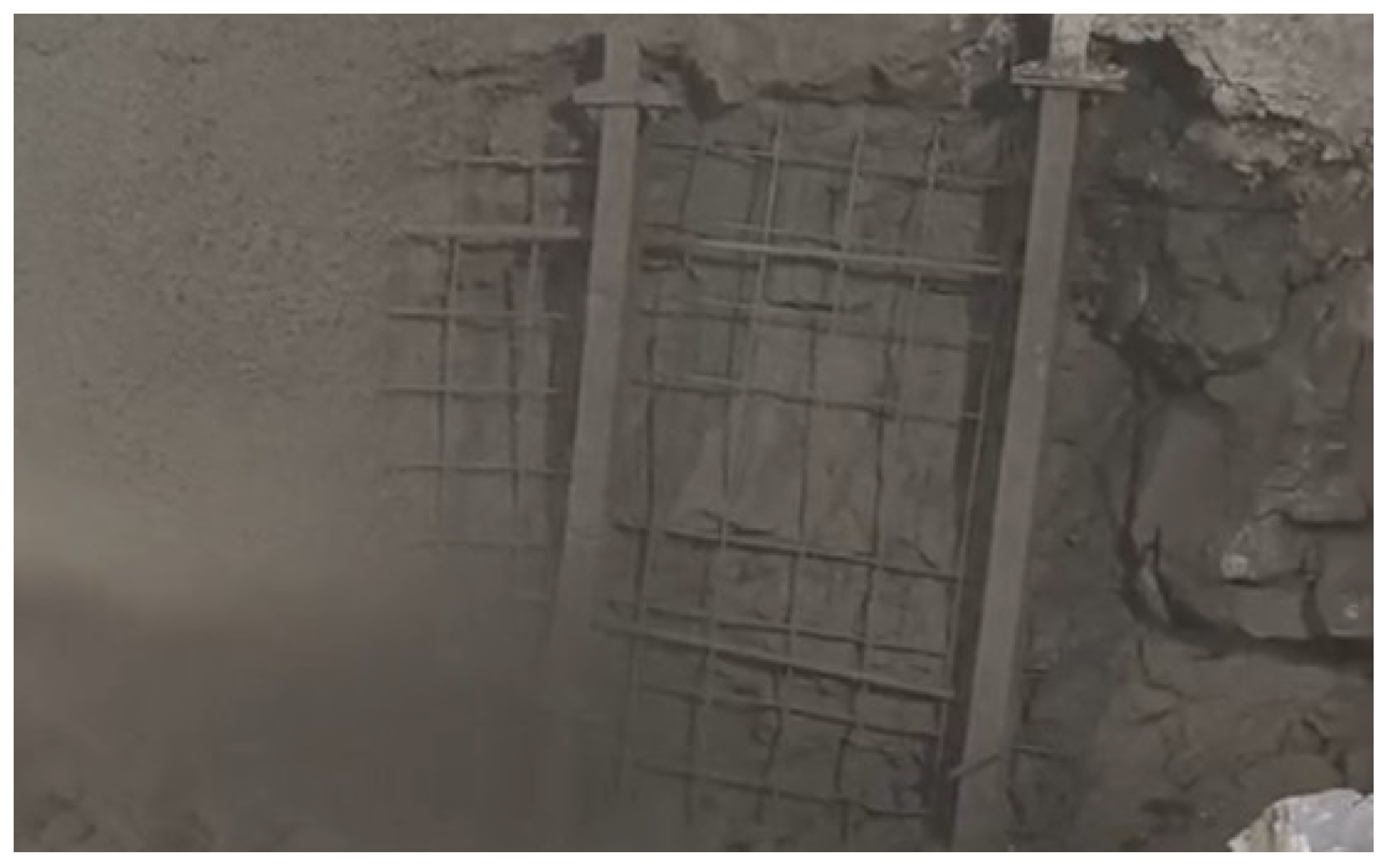
3.2.1. Patching Layer Spraying Experiment

The footstep planning for the pit-filling layer is carried out, with 12 footholds planned for the pit-filling layer to ensure the spraying coverage spans the entire pit-filling area, as shown in the circular region in Figure 18.
After planning the patching stopping points, the PDDL generates the spray gun action sequence for the patching task. This sequence completes the spraying at all the stopping points. Based on the spraying parameters and the required spraying thickness at each patching stopping point, the stopping time for each point is also planned, as shown in Figure 19.
Based on the patching action sequence, the patching spraying experiment is conducted, as shown in Figure 20. The contour map of the over-excavation and under-excavation values after completing the patching spraying is shown in Figure 21. At this point, the maximum over-excavation value is around 40 cm.

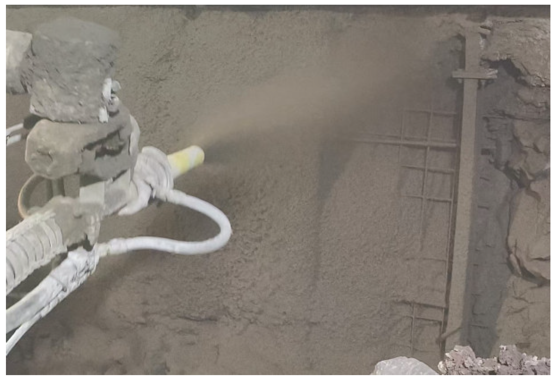
3.2.2. Filling Layer Spraying Experiment

After the patching of the tunnel, the spraying area is reclassified into layers. At this point, the spraying area only consists of the filling layer and the sweeping layer. A grid of stopping points is planned for the filling layer, as shown in Figure 22. The spray gun action sequence for the filling layer is then generated using the PDDL, as shown in Figure 23. Based on the filling action sequence, the filling layer spraying experiment was conducted, as shown in Figure 24. The contour map of the over-excavation and under-excavation values after completing the filling layer spraying is shown in Figure 25. At this point, the maximum over-excavation value is approximately 10 cm.

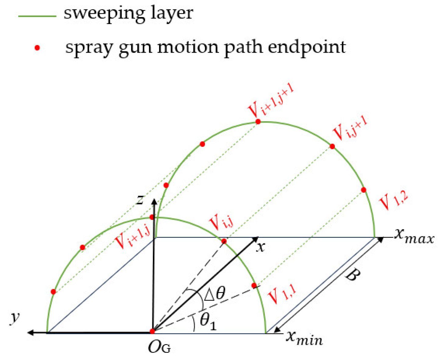
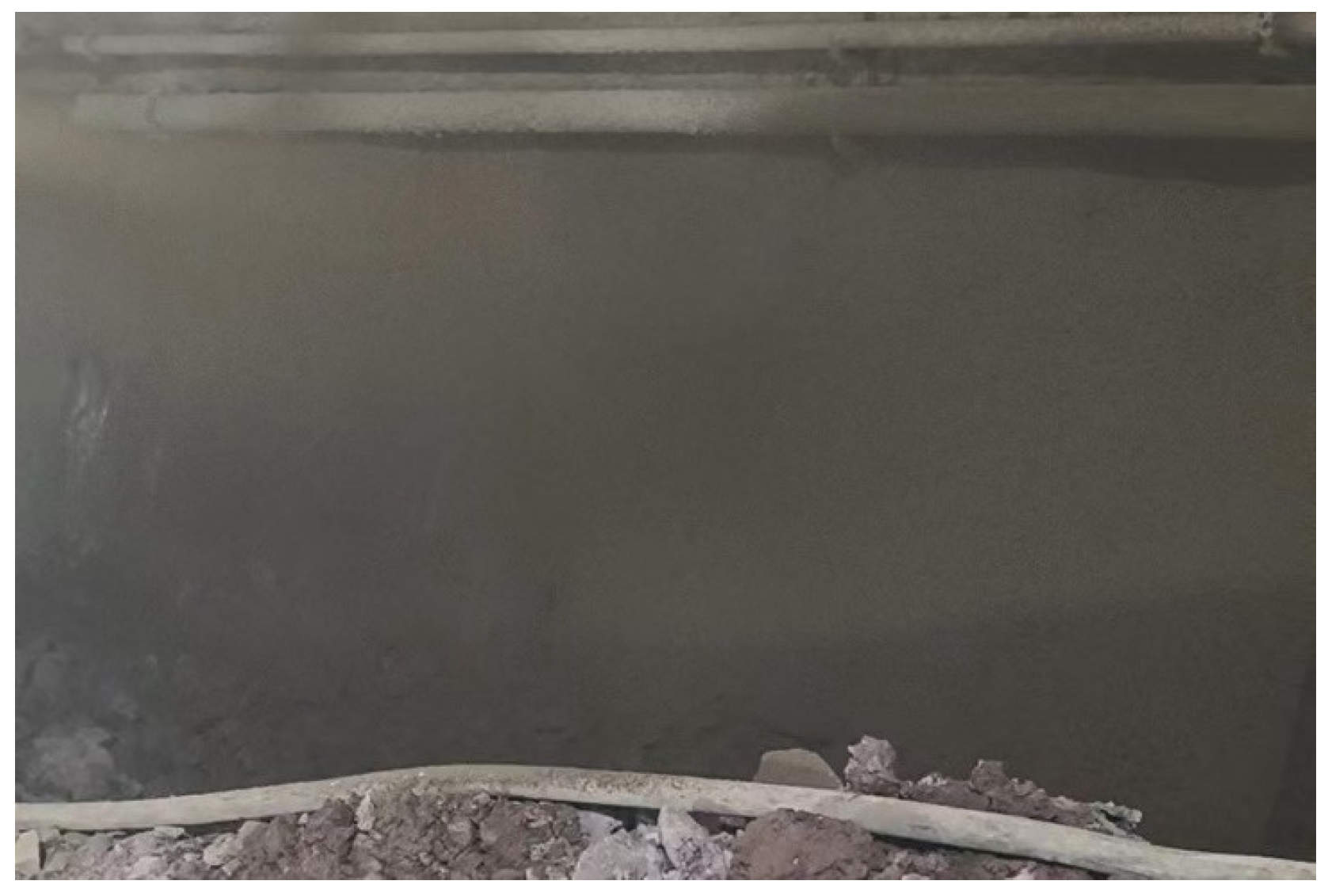
3.2.3. Sweeping Layer Spraying Experiment

After completing the filling layer, the spraying area is reclassified into layers. At this point, only the sweeping layer remains. The spray gun motion path endpoints for the sweeping layer are then planned, as shown in Figure 26. A total of 13 spray gun path endpoints are defined to ensure full coverage of the entire sweeping layer. Using the PDDL, the sweeping action sequence is generated, as shown in Figure 27. Based on this sweeping action sequence, a spraying experiment for the sweeping layer is conducted, as shown in Figure 28. The over-excavation and under-excavation contour map after the sweeping spraying is completed, as shown in Figure 29. At this point, the maximum over-excavation value is around 3 cm.

4. Conclusions

To evaluate the uniformity of the coating thickness, the average over-excavation value metric is introduced.
ω = i = 1 n C i i
w represents the average over-excavation value, and Ci denotes the over-excavation value in each grid cell. Figure 30 illustrates the relationship between w and the progression of task-layer spraying. As each task layer (patching, filling, and sweeping) is completed, w exhibits a decreasing trend.
The experimental results above indicate that the PDDL-based tunnel spraying task planning method proposed in this paper, which is based on a multivariable coating accumulation model, can effectively handle tunnel over-excavation and under-excavation. By using task-level planning, operational parameter planning, and action sequence planning, the complex tunnel spraying task is decomposed into a rational spray gun action sequence. This method effectively reduces the dependency on human experience. However, during the development of the concrete spraying accumulation model, the influence of the accelerator on the concrete accumulation thickness is not considered. Introducing this factor into the multivariable coating accumulation model would further optimize the spray gun action sequence and improve the smoothness of the tunnel surface after spraying.

Author Contributions

Y.H.: methodology, validation. W.S.: Conceptualization, writing—original draft. X.S.: Writing—review and editing, formal analysis. C.L.: Supervision. K.X.: Project administration. All authors have read and agreed to the published version of the manuscript.

Funding

This research received no external funding.

Institutional Review Board Statement

Not applicable.

Informed Consent Statement

Not applicable.

Data Availability Statement

Date are contained within the article.

Conflicts of Interest

The authors declare no conflicts of interest.

References

  1. Guo, Y.; Zuo, H.; Chen, X.; Zhu, J.; Ji, C.; Chen, Z. A Combinational Optimization Algorithm for Inverse Kinematics of an 8-DOF Redundant Manipulators. In Proceedings of the International Conference on Mechanism and Machine Science, Yantai, China, 30 July—1 August 2022; Springer: Berlin/Heidelberg, Germany, 2022; pp. 1089–1104. [Google Scholar]
  2. Gasparetto, A.; Vidoni, R.; Pillan, D.; Saccavini, E. Automatic Path and Trajectory Planning for Robotic Spray Painting. In Proceedings of the ROBOTIK 2012, 7th German Conference on Robotics, VDE, Munich, Germany, 21–22 May 2012; pp. 1–6. [Google Scholar]
  3. Liu, G.; Sun, X.; Liu, Y.; Liu, T.; Li, C.; Zhang, X. Automatic Spraying Motion Planning of a Shotcrete Manipulator. Intell. Serv. Robot. 2022, 15, 115–128. [Google Scholar] [CrossRef]
  4. Zaizheng, L.; Nianwen, Q.; Qingjian, Z.; Jianhua, L. Research on Intelligent Control System and Spray Path Planning Design of Spraying Manipulator. Tunn Construction. (Chin. Engl.) 2018, 38, 1391–1396. [Google Scholar]
  5. Xianchao, S. Research on Automated Operation Strategy and Trajectory Planning of Wet Spray Robotic Arm; Harbin Institute of Technology: Harbin, China, 2021. [Google Scholar]
  6. Antonio, J.K. Optimal Trajectory Planning for Spray Coating. In Proceedings of the 1994 IEEE International Conference on Robotics and Automation, San Diego, CA, USA, 8–13 May 1994; IEEE: New York, NY, USA, 1994; pp. 2570–2577. [Google Scholar]
  7. Freund, E.; Rokossa, D.; Roßmann, J. Process-Oriented Approach to an Efficient off-Line Programming of Industrial Robots. In Proceedings of the IECON’98, 24th Annual Conference of the IEEE Industrial Electronics Society (Cat. No. 98CH36200), Aachen, Germany, 31 August 1998; IEEE: New York, NY, USA, 1998; Volume 1, pp. 208–213. [Google Scholar]
  8. Arikan, M.S.; Balkan, T. Process Simulation and Paint Thickness Measurement for Robotic Spray Painting. CIRP Ann. 2001, 50, 291–294. [Google Scholar] [CrossRef]
  9. Yonggui, Z.; Yumei, H. New Model for Air Spray Gun of Robotic Spray-Painting. J. Mech. Eng. 2006, 42, 226–233. [Google Scholar]
  10. Sheng, W.; Chen, H.; Xi, N.; Chen, Y. Tool Path Planning for Compound Surfaces in Spray Forming Processes. IEEE Trans. Autom. Sci. Eng. 2005, 2, 240–249. [Google Scholar] [CrossRef]
  11. Guolei, W.; Qiang, Y.; Dongjing, M.; Ken, C.; Liqiang, W. Multivariable Coating Thickness Distribution Model for Robotic Spray Painting. J. Tsinghua Univ. (Sci. Technol.) 2017, 57, 324–330. [Google Scholar]
  12. Qi, S.; Jiang, D.; Sun, Y.; Xiong, T.; Wei, Y.; Xu, Z. IMPSO-Based Trajectory Optimization and Control of Liquid Apply Sound Deadener Spraying Robot for High-Speed Train. IEEE Access 2024, 12, 127149–127164. [Google Scholar] [CrossRef]
  13. Yu, X.; Cheng, Z.; Zhang, Y.; Ou, L. Point Cloud Modeling and Slicing Algorithm for Trajectory Planning of Spray Painting Robot. Robotica 2021, 39, 2246–2267. [Google Scholar] [CrossRef]
  14. Ji, J.; Xu, J. Coating Thickness Distribution Model with Variable Velocity for Super-Large Plane Robot Spraying. Mach. Tool Hydraul. 2023, 51, 35–41. [Google Scholar]
  15. Dai, Y.; Xiang, C.; Zhang, Y.; Jiang, Y.; Qu, W.; Zhang, Q. A Review of Spatial Robotic Arm Trajectory Planning. Aerospace 2022, 9, 361. [Google Scholar] [CrossRef]
  16. Fikes, R.E.; Nilsson, N.J. STRIPS: A new approach to the application of theorem proving to problem solving. Artif. Intell. 1971, 2, 189–208. [Google Scholar] [CrossRef]
  17. Erol, K.; Hendler, J.A.; Nau, D.S. Semantics for Hierarchical Task-Network Planning; Citeseer: State College, PA, USA, 1994. [Google Scholar]
  18. Aeronautiques, C.; Howe, A.; Knoblock, C.; McDermott, I.D.; Ram, A.; Veloso, M.; Weld, D.; Sri, D.W.; Barrett, A.; Christianson, D.; et al. Pddl|The Planning Domain Definition Language; Technical Report; Yale University: New Haven, CT, USA, 1998. [Google Scholar]
  19. Jiang, Y.; Zhang, S.; Khandelwal, P.; Stone, P. Task Planning in Robotics: An Empirical Comparison of Pddl-and Asp-Based Systems. Front. Inf. Technol. Electron. Eng. 2019, 20, 363–373. [Google Scholar] [CrossRef]
  20. Yuhui, G.; Ming, S.; Dunbo, C.; Gong, Z. Research of a General Teleoperation Task Intelligent Planning Method. J. Deep. Space Explor. 2021, 8, 140–146. [Google Scholar]
  21. Vallati, M.; Chrpa, L.; McCluskey, T.L.; Hutter, F. On the Importance of Domain Model Configuration for Automated Planning Engines. J. Autom. Reason. 2021, 65, 727–773. [Google Scholar] [CrossRef]
Figure 1. Estimation of the vehicle body pose of the wet spraying trolley.
Applsci 15 05187 g001
Figure 2. Schematic diagram of the tunnel profile.
Applsci 15 05187 g002
Figure 3. Static coating accumulation distribution.
Applsci 15 05187 g003
Figure 4. Dynamic coating accumulation distribution.
Applsci 15 05187 g004
Figure 5. Schematic diagram of pit-filling operation point planning.
Applsci 15 05187 g005
Figure 6. Schematic diagram of pit-filling layer stance point calculation.
Applsci 15 05187 g006
Figure 7. Schematic diagram of optimal spraying distance.
Applsci 15 05187 g007
Figure 8. Distribution of grid stance point positions in the filling layer.
Applsci 15 05187 g008
Figure 9. Schematic diagram of sweep layer path endpoint calculation.
Applsci 15 05187 g009
Figure 10. Modeling process of tunnel spraying task planning.
Applsci 15 05187 g010
Figure 11. Schematic diagram of the PDDL domain file structure.
Applsci 15 05187 g011
Figure 12. Schematic diagram of action definition.
Applsci 15 05187 g012
Figure 13. Tunnel spraying task domain knowledge model.
Applsci 15 05187 g013
Figure 14. Schematic diagram of the PDDL problem file structure.
Applsci 15 05187 g014
Figure 15. Selection of the tunnel area to be sprayed.
Applsci 15 05187 g015
Figure 16. Contour map of over-excavation and under-excavation in the area to be sprayed.
Applsci 15 05187 g016
Figure 17. Task hierarchy division.
Applsci 15 05187 g017
Figure 18. Stance point planning.
Applsci 15 05187 g018
Figure 19. Pit-filling action sequence.
Applsci 15 05187 g019
Figure 20. Pit-filling layer spraying.
Applsci 15 05187 g020
Figure 21. Contour map of over-excavation and under-excavation after pit filling.
Applsci 15 05187 g021
Figure 22. Grid stance point planning.
Applsci 15 05187 g022
Figure 23. Filling action sequence.
Applsci 15 05187 g023
Figure 24. Filling layer spraying.
Applsci 15 05187 g024
Figure 25. Contour map of over-excavation and under-excavation after filling.
Applsci 15 05187 g025
Figure 26. Planning of spray gun motion path endpoint.
Applsci 15 05187 g026
Figure 27. Sweep action sequence.
Applsci 15 05187 g027
Figure 28. Sweep layer spraying.
Applsci 15 05187 g028
Figure 29. Contour map of over-excavation and under-excavation after sweeping.
Applsci 15 05187 g029
Figure 30. Average over-excavation value of the tunnel area to be sprayed.
Applsci 15 05187 g030
Table 1. Definition of related content in the PDDL domain file for spraying task planning.
TypesPredicatesFunctionsAction
patching fill surface—wpat ?robotdistance ?wp1 ?wp2move1
Lm Cm—surfacenext-to ?wp1 ?wp2robot_speed ?robotspray1
robotvisited ?wpT ?wpmove2
unvisited ?wp spray2
is-fill ?wp L_motion
is-unfill ?wp C_motion
Disclaimer/Publisher’s Note: The statements, opinions and data contained in all publications are solely those of the individual author(s) and contributor(s) and not of MDPI and/or the editor(s). MDPI and/or the editor(s) disclaim responsibility for any injury to people or property resulting from any ideas, methods, instructions or products referred to in the content.

