The team-communication modeling framework and analysis methodology are developed to be applied to multi-unit NPP accident management. To evaluate their feasibility and functionality, we consulted with five subject-matter experts (a nuclear engineering professor, a nuclear industry project leader, and three senior researchers in the nuclear science research center) and obtained two multi-unit accident scenarios. We also analyzed the materials (local nuclear industry meeting presentations, local research papers, and reports) on multi-unit accident management in South Korea to complement the information on the accident scenarios, and we justified our modeling decisions (such as the decision to focus on mobile equipment modeling) to the experts. In this paper, due to content limitation, we reported one multi-unit accident scenario and our FRAM model development.
3.7.1. Background Information
Some background information is needed to increase the readability of the accident scenario and the FRAM-based process model. We briefly described the emergency-response teams and the emergency mobile equipment as follows.
The NPP operation in South Korea is divided per reactor unit [
46,
51,
52]. One reactor unit is operated by one team called the main control room (MCR) team, consisting of the leader, shift supervisor, and four members: a reactor operator, a turbine operator, an electrical operator, and a shift technical advisor. MCR may request support from field operators (FO). Upon emergencies, MCR requests the creation of emergency-response teams (ERTs) at the safety center (SC). The ERTs consist of an operating support center (OSC), a technical support center (TSC), and an emergency operation facility (EOF). The ERTs are active when the team leader is present. The characteristics of the ERTs are as follows (we provided the ERT descriptions based on the latest obtainable information; however, these descriptions might change as the accident-management plan is updated from time to time).
An operating support center (OSC) covers one NPP site. It performs emergency maintenance, material acquisition, fire extinguishment, and personnel rescue. By default, OSC takes orders from TSC. When TSC is not yet active, it may take orders from EOF or decide by itself or by discussions with MCR and SC. Fire extinguishing and rescue tasks require OSC to interact with multiple teams, such as the medical team, field operators, and the local fire department. A technical support center (TSC) is responsible for one reactor unit and one dedicated TSC for one MCR. TSC takes the decision-making authority from MCR and hands it over to EOF when EOF is active. If EOF is not assembled or not yet active, TSC receives the requests from MCR, analyzes them, decides and orders countermeasures back to MCR or OSC/SC, and then updates the plant status to the public. When EOF is active, TSC recommends countermeasures to EOF to support EOF decision-making. By default, TSC relays the EOF decisions to other teams since EOF has a large work scope. Besides that, TSC performs radioactive analysis, distributes protective equipment to the personnel in the field, restricts access to dangerous areas, and orders radiation decontamination tasks to field operators. An emergency operation facility (EOF) covers one NPP site and it is located outside of the site (off-site). EOF holds the highest authority upon activation, and it is responsible for returning the NPP to safety. Critical decisions such as emergency-phase selection, habitability evaluation, resident evacuation, medical support, information sharing with the media, and personnel management are taken by the EOF. It receives status updates from TSC by default and orders accident countermeasures such as the deployment of mobile equipment. It may interact with all internal emergency-response teams as well as external organizations and communities. It interacts with NPPs in other locations to request support. In general, EOF is the contact point for external interactions.
The Fukushima accident brought new concerns to the safety regulations of the nuclear industry; thus, countermeasures were prepared [
53]. One of them is the multi-barrier accident coping strategy (MACST) developed in South Korea, in accordance with the United States’ “Diverse and Flexible Coping Strategy”, which aims to prevent and mitigate nuclear core damage by implementing multiple fixed and mobile equipment to recover/maintain power supply, restore the safety functions (core cooling), and complete the safe shut-down of the plant. MACST contains three phases, starting from Phase 1 to Phase 3, and mobile equipment can be requested when Phase 2 starts. The major pieces of mobile equipment used in Phase 2 are a 1 MW mobile generator, high-pressure mobile pump, and low-pressure mobile pump; in Phase 3, they are a 3.2 MW mobile generator and high-flow-rate sea-water pump. A study reported the development status of the MACST operating guidelines, which consist of 14 guidelines, while details on MACST and its operations were being determined and tested for feasibility [
54,
55,
56]. However, the task flow of deploying the mobile equipment (which should be different per equipment type) was not yet determined nor reported in official information. Through discussions with subject-matter experts, we were able to obtain the estimated task flow of mobile equipment deployment, and we referred to that information to create the FRAM-based process model. For example, the mobile equipment driver moves the equipment to the required location, the OSC operators prepare and install it, and the FO operates it. However, this task flow and the performers might be updated in the future.
3.7.2. The Multi-Unit Accident Scenario
During our research project, a group of NPP accident prevention experts developed a few multi-unit accident scenarios and using those scenarios, we were able to test the feasibility of our modeling framework and methodology. We selected one scenario to be the case study in this paper; however, we are unauthorized to disclose the full details.
Thus, we describe the accident scenario based on its main events, as follows. A certain NPP has six reactors. Due to an earthquake of 0.3 G scale, the power supply to all reactors is lost. The automatic shut-down and power loss are confirmed; an accident type called “loss of off-site power/LOOP” is decided. The operational status of some emergency power supply equipment (emergency diesel generator, turbine-driven auxiliary feed-water pump, etc.) is checked. Part of the equipment appears to be not working, and field operators are sent to operate them on site. MCR starts the procedure to diagnose the accident and, upon finding that all AC power sources are lost, proceed to the indicated emergency procedure. Countermeasures, such as opening dump valves, are taken. Reports from the field operators are received, which mention that the power generators are not operable. The accident has entered a prolonged power loss state, and it is decided to be a type called “extended loss of AC power/ELAP”. MCR follows the corresponding accident guideline to stop unnecessary power load requests for multiple pieces of mobile equipment to the SC, which receives the requests and calls the drivers located outside the site. The drivers arrive at the mobile equipment storage and prepare and drive them to the installation location. SC checks the road for damages and starts removing the debris. TSC is active and oversees the mobile equipment assignments. OSC is active and assigns members to move to mobile equipment installation locations and prepares for installation. EOF is active and takes over the mobile equipment assignments. TSC requests additional mobile equipment for EOF. EOF requests additional mobile equipment to other NPP sites, through SC. SC reports that the other NPP sites agree to send the equipment and EOF assigns the mobile equipment for the whole site. MCR stops the unnecessary load; however, the nuclear core temperature reaches 649 °C, which is an entry condition to severe accident-management guidelines. While MCR is following the guidelines, mobile equipment arrives (driven by SC drivers) and is installed (with the help of OSC), with permissions from TSC, who acquired the assignments from EOF. Mobile equipment from other NPP sites arrives and is received by SC drivers, who take them to the installation location. The operation of the mobile equipment (by field operators) is successful, the power supply is recovered, and the core cooling is ongoing. The situation is stable, and the accident scenario is finished.
3.7.3. The Application of Team-Communication Modeling Framework
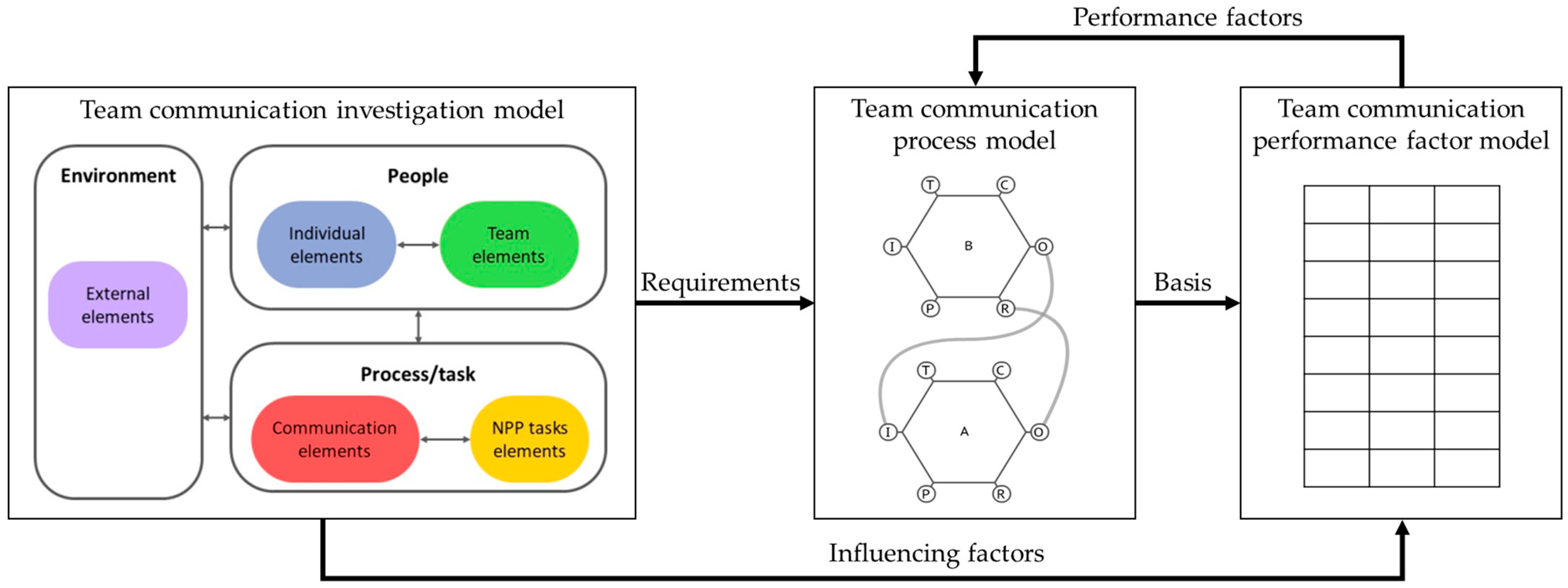
Among the three models in the framework, two of them, the team-communication investigation model and the performance-factor model, are mostly static, and the remaining process model is dynamic, which represents the specific communication process of an NPP emergency. Although the three models interact (
Figure 1), the investigation model and performance-factor model mainly provide input to the process model as influencing and performance factors, respectively (the feedback loops were created to maintain consistency in case the process model contains new influencing/performance factors). The three model concepts were developed at the same time; however, the contents of the investigation model were developed first [
29] and followed by the contents of the performance-factor model (
Table 1). The contents of the process model depend on the communication activities, which depend on an accident scenario. Thus, the accident scenario described above mainly affects the FRAM-based team-communication process model. We applied the three-step team-communication analysis methodology described in
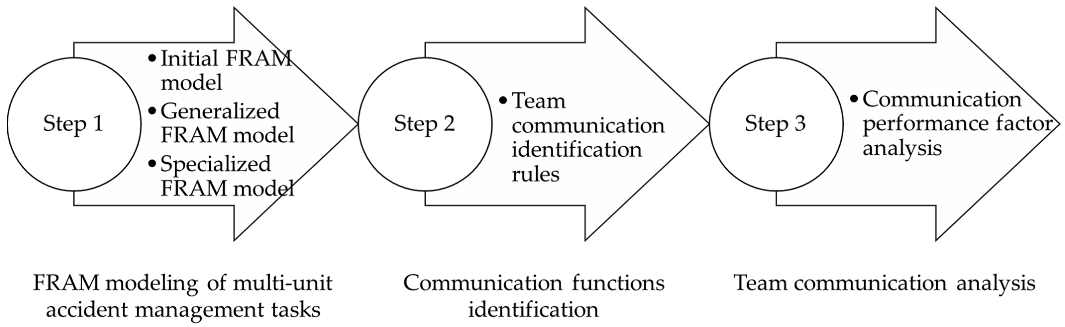
Section 3.6 as follows.
The first analysis, FRAM modeling of multi-unit accident-management tasks, consists of the following:
Initial FRAM model development
Generalized FRAM model development (and definition of analysis scope)
Specialized FRAM model(s) development
Function performer and variability assignments
The initial FRAM model covers the entire multi-unit accident scenario. We identified the functions and connected them using the functions aspects (Input, Time, Precondition, Control, Resources, and Output) and specified their performers (whenever possible). Basically, we performed the function identification by following the FRAM guidelines [
43]. Modeling the entire accident scenario led to a model with many interconnected functions; this model ended up with 79 functions. Although comprehensive, this model was overly complicated and impractical. The initial FRAM model is generalized in the next analysis.
The generalized FRAM model is a compact version of the initial FRAM model but still covers the entire accident scenario. We performed generalization by combining two or more functions into one when (1) the nature of the functions was similar, and they were performed by the same performer/ERT, or (2) the flow of functions indicated an integrated goal. For example, functions “Announce emergency code white”, “Announce emergency code blue”, and “Announce emergency code red” were performed by MCR, and they were combined into a function named “Announce emergency code: white/blue/red”. Multiple functions related to the 1 MW mobile generator were combined into a function named “Move~operate 1 MW mobile generator”. We also combined or withdrew several background functions that did not contribute to our interest (a foreground function is the one being analyzed, whereas a background function is the one that affects, as context or environment of, the foreground function. In this paper, the term function generally refers to the foreground function). For example, background functions “Provide computer-based procedure” and “Provide paper-based procedure” were combined into “Provide procedures”, and functions related to local resident evacuation were eliminated.
Table 2 lists the number of functions per performer/ERT and function examples. In total, this model consisted of 40 functions, of which 14 background functions supported 26 foreground functions.
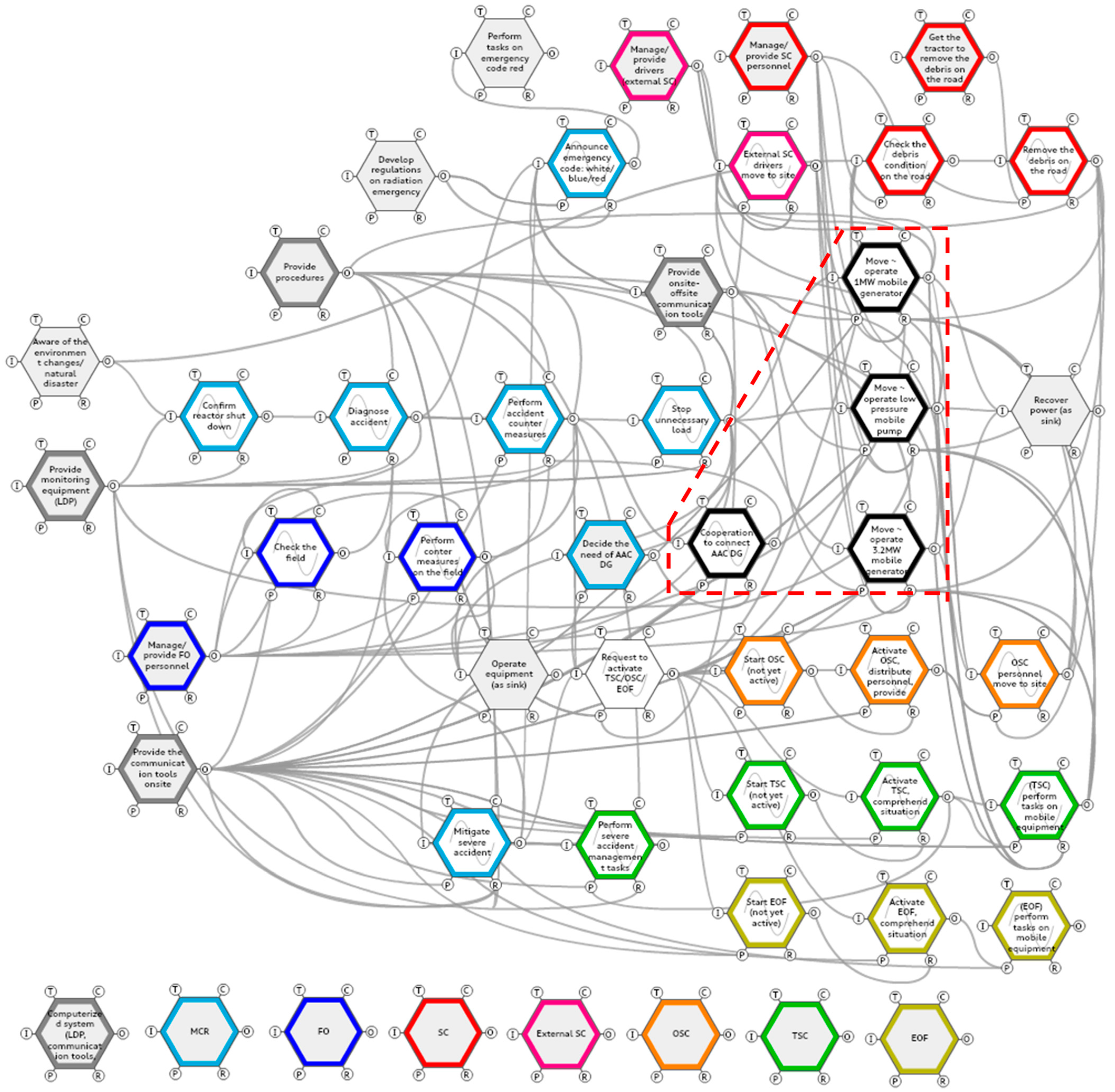
While creating the (previous) initial FRAM model, we discovered that the tasks related to the emergency equipment (three mobile and one fixed piece) took a considerable part of the entire accident-management tasks. We confirmed this finding while we revisited the initial FRAM model to create the generalized FRAM model. Simultaneously, those emergency equipment-related functions also involved the highest number of teams who needed to work together. The task related to the 1 MW mobile generator, represented by the function named “Move~operate 1 MW mobile generator”, required MCR to send a request for the equipment, SC to process the request, TSC or EOF to grant the request and approve the equipment operation, external SC drivers to move the equipment, OSC to support the installation, FO to operate the equipment, and back to MCR to confirm the equipment operation’s effect and report to TSC or EOF. From discussions with subject-matter experts, the tasks related to mobile equipment are currently of high interest, and procedures defining those tasks are being tested/updated. Thus, in this study, we decided to set the analysis scope of team communication to the four emergency equipment-related functions, namely: the “Cooperation to connect AAC DG” function, the “Move~operate 1 MW mobile generator” function, the “Move~operate low-pressure mobile pump” function, and the “Move~operate 3.2 MW mobile generator” function. The generalized FRAM model is shown in
Figure 4, where the four emergency equipment-related functions are marked with a dashed line shape. These functions have denser connections compared to others (except the supporting background functions), reflecting their importance. Thus, they were selected as the analysis target.
For each of the four functions included in the analysis (hereafter, we used the term “parent function”), a specialized FRAM model was created, with its scope matched to the parent function, not the entire accident scenario.
Table 3 lists each parent function’s name and its corresponding FRAM model name. Following the FRAM guidelines, the name of a function is in a verb form, and the name of a model is in a noun form. Due to space limitations, we mainly present the result of the low-pressure mobile pump operation model.
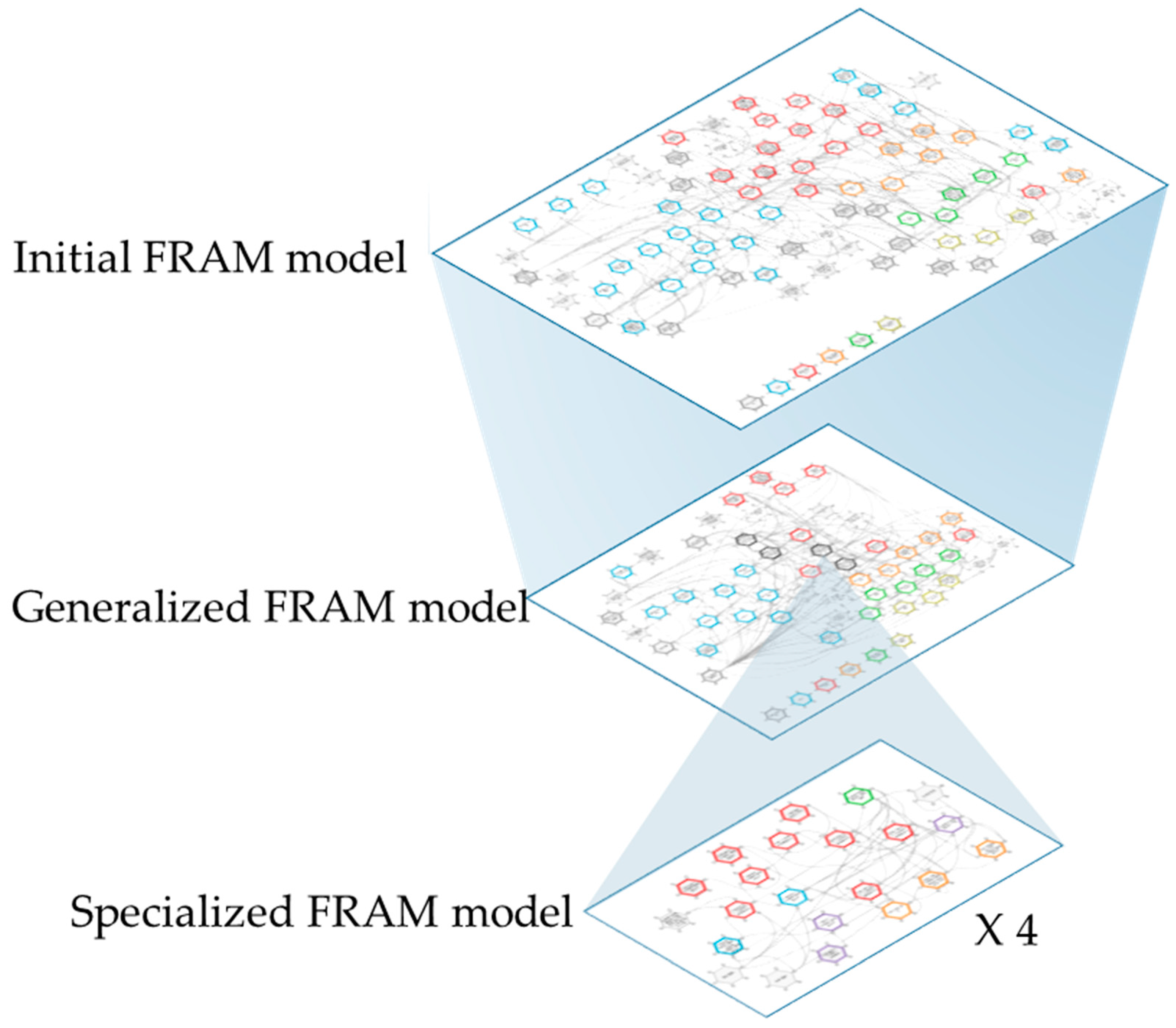
The concept of the three model types, i.e., the initial, generalized, and specialized FRAM models, is illustrated in
Figure 5. The initial and generalized FRAM model had the same analysis scope, namely the entire NPP accident. However, the scope of the specialized FRAM model is smaller; it covers one pre-selected function of the generalized model. In total, four specialized FRAM models were created, one for each of the parent function. These specialized FRAM models allow us to perform team-communication analysis without overcomplicated functions and aspects.
Two steps of model development were carried out to create the specialized FRAM model. We performed the same model development method for all four specialized FRAM models and described the method in detail using the “Low-pressure mobile pump operation” model.
The first step of model development is to revisit the initial FRAM model and return the parent function to the original functions. The parent function “Move~operate low-pressure mobile pump” in the generalized FRAM model was returned to the series of functions it represented in the initial FRAM model, namely “Decide equipment allocation”, “Prepare equipment transport (on-site)”, “Transport equipment”, and so on. We examined all the aspects of the parent function and included them in the aspects of the specialized FRAM model. For instance, one of the inputs of the “Move~operate low-pressure mobile pump” function is “Request/re-request equipment”. This aspect is included in the specialized FRAM model. Then, since the “Low-pressure mobile pump operation” model covered only one piece of equipment, its functions were specialized. The accident scenario involved two types of low-pressure mobile pumps, one for primary cooling (reactor cooling system) and another for secondary cooling (steam generator). Based on our discussions, both pumps are almost always requested together (as in the scenario); however, since they are different function-wise, we differentiated them in the model, adding the words “primary” and “secondary”. The functions in the “Low-pressure mobile pump operation” model were specialized as follows: “Decide equipment allocation” became “Request mobile pump”, “Prepare equipment transport (on-site)” became “Prepare mobile pump for transport—primary” and “Prepare mobile pump for transport—secondary”, and so on. This first step of model development merely returned the parent functions into their initial forms with some adjustments; to increase the value of the model and the subsequent team-communication analysis, we applied the principle of work-as-imagined versus work-as-done.
The second step of specialized FRAM model development is the application of the principle of work-as-imagined versus work-as-done (WAI vs. WAD) [
57]. WAI is the series of works to achieve a certain goal that is planned by the systems designers, and they are usually described and provided to the workers/operators through procedures, guidelines, training course content, manuals, etc. However, the operators may perform the works differently and still achieve the prescribed goal; those works are WAD. Although FRAM can contain both WAI and WAD, its value is higher when it represents WAD because then real variabilities could be reflected and analyzed, and practical improvements could be suggested.
So far, the initial FRAM model and the generalized FRAM model have been developed by following WAI, namely the “imagined” accident scenario. This is inevitable since WAD specifications will require real multi-unit accident-management experiences, which are unavailable at the moment in South Korea’s nuclear industry. For the specialized FRAM model, we made efforts to apply the WAD principle whenever possible and reliably, with feedback from the subject-matter experts. Our strategies in applying WAD principles to the specialized FRAM model are summarized in
Table 4, along with the changes in the model and the justification of the strategy.
The resulting “Low-pressure mobile pump operation” model after the first step and second step of model development is shown in
Figure 6. After the second step of model development, in which we applied the WAD principle, additional functions and aspects were found to be necessary and added, as shown in
Figure 6b’s higher number of functions and denser connections between functions.
Figure 6.
The “Low-pressure mobile pump operation” specialized FRAM model (a) After the first step of model development; (b) After the second step of model development.
Figure 6.
The “Low-pressure mobile pump operation” specialized FRAM model (a) After the first step of model development; (b) After the second step of model development.
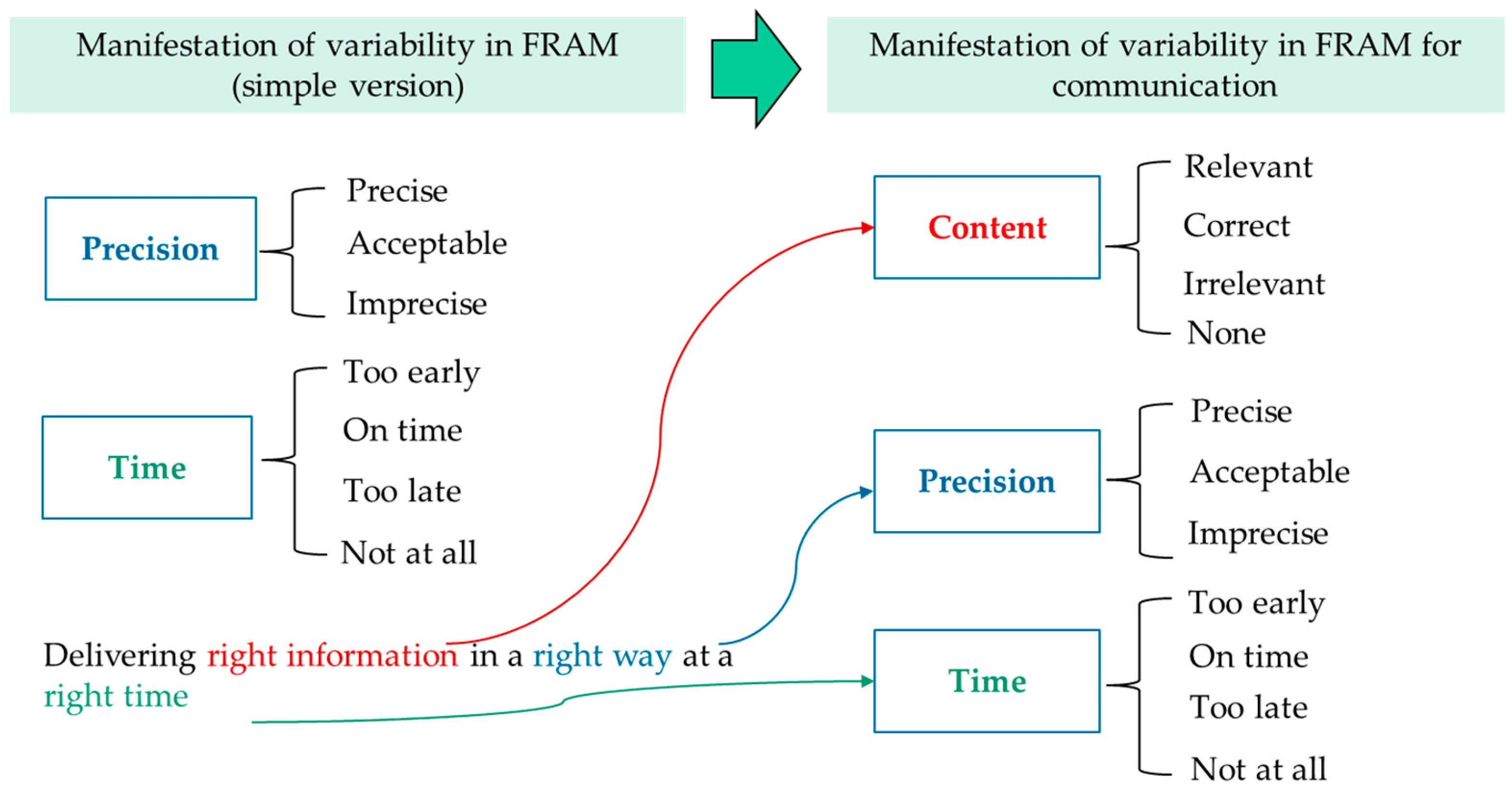
The function performers were confirmed, and the variabilities were assigned by following the FRAM guidelines, which described that variability has consequences in terms of time and precision. To support team-communication analysis, we added content variability as the third variability.
Table 5 lists examples of variability assignments. The function “Request mobile pump—primary” is performed by one of the MCR members. Thus, the category is “Human”. This function can have multiple outputs, but it has one main output, namely “Mobile pump request—primary”. The variabilities are assigned to this main output. In this case, we decided that this function is performed on time, precisely, and with correct content. The rationale of these variabilities’ assignments is that the requested task is not complicated, and the content is brief.
In the identification of communication function, we identified the functions related to team communication from the specialized FRAM model using the conditions described in
Section 3.6. The result is the specialized FRAM models with communication functions marked, without any function or aspect modification.
In team-communication analysis, the aspects of the communication functions are elaborated by considering the communication performance factors from the performance-factor models (
Section 3.3), and required functions are added.
There are two strategies to implement the team-communication performance factors. The first strategy is to include the performance factors as aspects of the FRAM model. Those performance factors under the categories of precondition, resource, control, and time factors can be modeled as respective aspects. For example, in the “Low-pressure mobile pump operation” model, the “Request mobile pump—primary” function has been identified as a communication function. By consulting the performance factors, we were able to elaborate the function to analyze team communication. This function’s aspect elaboration is carried out for all identified communication functions.
Table 6 shows the aspects elaboration of a “Request mobile pump—primary” function. Each aspect was analyzed and added when needed. The Input and Output aspects have no addition, while the remaining aspects require few additions. This function has three Preconditions, and two of them are matched to the performance factors. They were not revised. The third precondition, “Knowledge of mobile equipment operation”, was elaborated to include the “Team member’s role definition related to communication” performance factor (no. 23); and a new Precondition was added by referring to “Permission required to process the message” performance factor (no. 24), and named “Condition: MCR leader’s approval is obtained”.
Figure 7a shows the “Low-pressure mobile pump operation” model after communication functions were identified, which are marked in red while the functions and aspects were unchanged from the previous version shown in
Figure 6b.
Figure 7b shows the “Low-pressure mobile pump operation” model after team-communication analysis, where the previously identified communication functions’ aspects were elaborated. Seven functions were also found to be necessary as the provider of the new aspects and they were added, marked in yellow.
Figure 7.
The “Low-pressure mobile pump operation” specialized FRAM model (a) The communication functions are marked after communication functions identification (step 2 analysis); (b) Additional functions are marked after team-communication analysis (step 3 analysis).
Figure 7.
The “Low-pressure mobile pump operation” specialized FRAM model (a) The communication functions are marked after communication functions identification (step 2 analysis); (b) Additional functions are marked after team-communication analysis (step 3 analysis).
The second implementation strategy is to utilize the remaining performance factors that could not be added as aspects of a communication function to update the function variability. For example, the performance factor of work experience tends to aggravate the variability since the personnel of ERTs have limited hands-on experience in multi-unit NPP accidents.


