
BPriS: Disciplined Agile Delivery Planning Method Based on Work Items List Pattern Applied to Prioritized Semantically Coupled Software Functions Derived from Business Process Model and Software Functional Pattern


Abstract
1. Introduction
- The concept of Disciplined Agile Functional Ordered Work Items List (DA-FOWIL)—includes an ordered work items list, based on software functions (SF) (derived from business processes and software functional patterns) and work items list patterns. The created DA-FOWIL work items list could be used in iterations planning of DA-based software development;
- The method BPriS (Disciplined Agile Delivery Planning Method Based on Work Items List Pattern Applied to Prioritized Semantically Coupled Software Functions Derived from Business Process Model and Software Functional Patterns)—for the creation of DA-FOWIL, based on business process model mapping to software functions, software development prioritization, semantic coupling of software functions, technology-dependent software functional patterns and work items list patterns.
2. Background
2.1. Disciplined Agile Delivery Approach
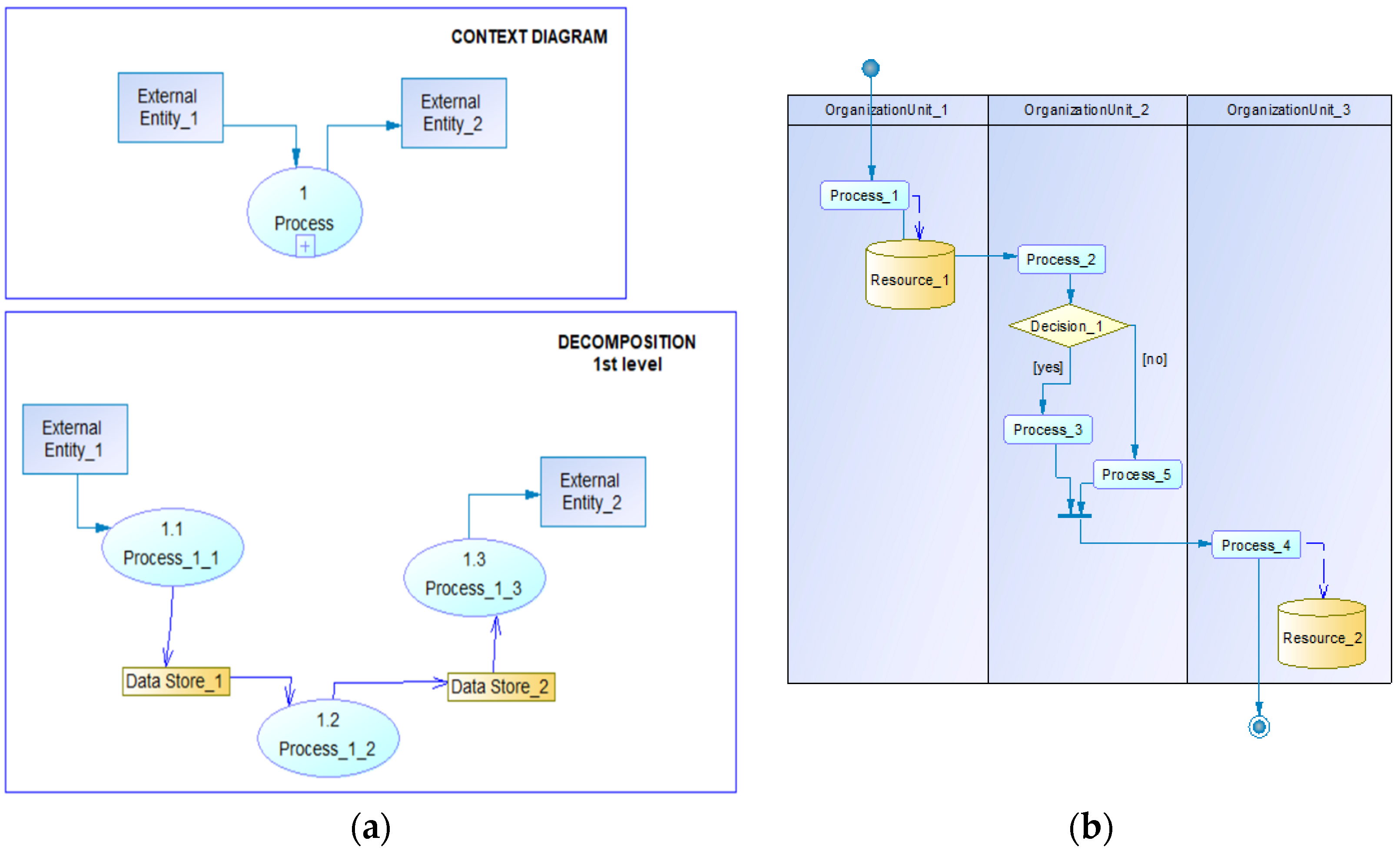
2.2. Business Process Modeling
3. Related Work
3.1. Business Process Mapping to Software Design
3.2. Software Semantic Coupling
3.3. Software Functional Patterns
3.4. Agile Software Development Planning and Automation
3.5. Agile Software Release Planning and Prioritization
3.6. Workflow Patterns and Software Development Work Items List Patterns
4. Materials and Methods
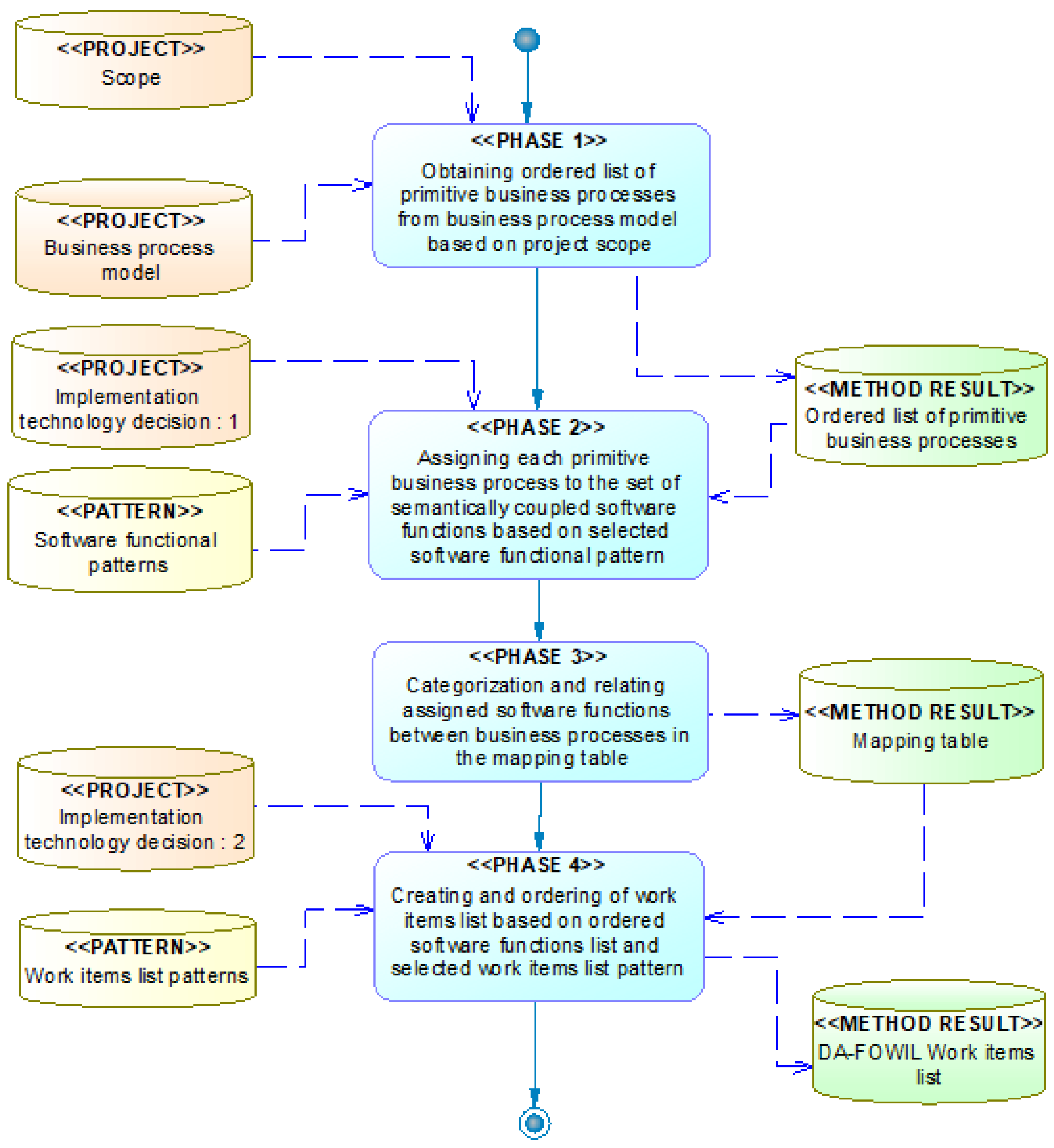
4.1. The Proposed Method
- Phase 1—Obtaining an ordered list of primitive business processes from a business process model based on a project scope. Fageha and Aibinu [149] highlighted that the proper scope boundaries should be set with stakeholders’ participation in the definition of future product elements.
- Phase 2—Assigning each primitive business process to the set of semantically coupled software functions based on a selected software functional pattern;
- Phase 3—Categorization and relating assigned software functions between business processes in the mapping table;
- Phase 4—Creating and ordering of a work items list based on an ordered software functions list and selected work items list pattern.
4.2. Obtaining Ordered List of Primitive Business Processes from Business Process Model Based on Project Scope
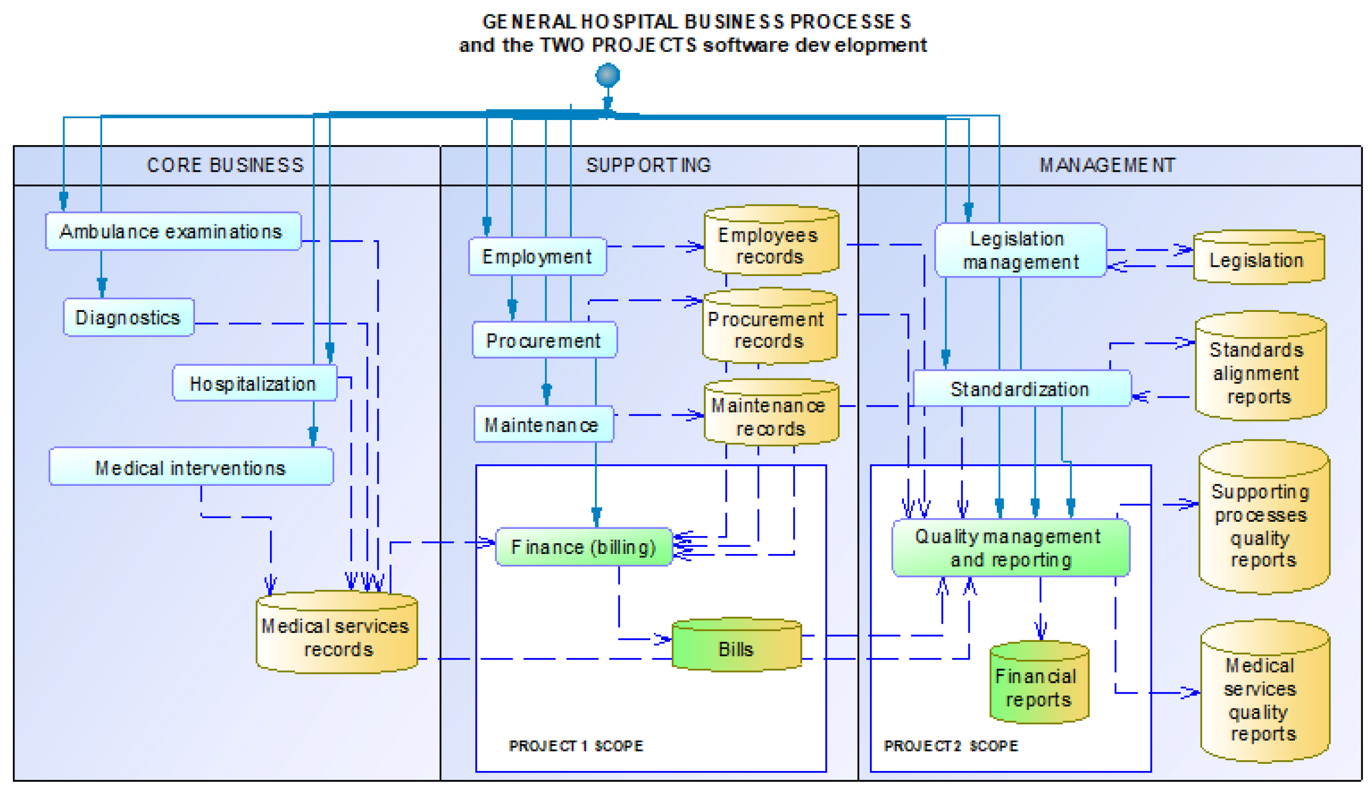
- Initial categorization of enterprise business processes could be performed at the global level, according to Rajarathinam et al. [32] as management process, operational process and the supportive process. Figure 6 presents an abstract business process model with categorization of business processes according to [32], with addition of having both “core business” term proposed in this manuscript as synonym to “operational” business processes. This way, categorization from [32] was enhanced and visualized at Figure 6.
- 2.
- Business processes segmentation, according to the project scope—some business process models are widely set to enable broader process context understanding. Usually, not all business processes will be automated, i.e., supported by software functions within the project scope. In such cases, there should be business processes segmentation conducted, where primitive business processes that are out of project scope should be eliminated from further processing in this method. (Figure 7).
- 3.
- Selection of primitive processes within the project scope and their chronological ordering—extracted primitive business processes from previous phase should be ordered in a list, following a chronological order at the business process model, which follows the order of these processes in real organization.
- Process_1_1
- Process_2_1
- Process_2_2
- Process_2_3
- Process_2_4
4.3. Assigning Each Primitive Business Process to the Set of Semantically Coupled Software Functions Based on the Selected Software Functional Pattern
- Selection of a software functional pattern, according to previously chosen technology for software implementation in the project. Software functional patterns consist of sets of abstract software functions mutually related for their functional purposes. This close relation between software functions enables their semantic coupling. Figure 8 presents an example of a software functional pattern, illustrated with an abstract UML use case diagram [150].
- Each primitive process from the list created in a previous phase is categorized as “input”, “processing” or “output” dominant.
- 3.
- According to the classification (“input”, “output”, “processing”), items from the software functional pattern are attached to this primitive business process, to represent the software support. This way, the first type of semantic coupling between software functions is applied—mutual close interaction of software functions from the software functional pattern is transferred to the set of software functions that support each primitive business process.

4.4. Categorization and Relating Assigned Software Functions Between Business Processes in the Mapping Table
- Categorization of software functions in one row—derived software functions belonging to one primitive business process-assigned set are organized in three categories: “precondition” (enables “first priority”), “first priority” (“need to have”), “second priority” (“nice to have”). In Figure 8, the “extend” stereotype represents the relationship between first priority functions (that are directly accessible by the user/actor at UML diagram) and “second” priority functions that extend the basic functionality. This categorization of first/second/precondition software functions represents the relationship with the business process supported by these software functions, not the implementation order.
- Relation between software functions from neighboring rows—primitive business process-assigned sets of software functions are symmetrically related: “precondition” software functions from the next row are related to “first priority“ software functions from previous row in the mapping table. This is the second type of semantic coupling—between software functions of neighbor business processes’ supporting software functions.
4.5. Creating and Ordering of Work Items List Based on Ordered Software Functions List and Selected Work Items List Pattern
- Ordering of derived software functions should be conducted in three levels;
- Selection of work items list pattern, according to the selected implementation technology for the project;
- Applying the selected work items list pattern to implement each software function from the ordered software functions list.
4.5.1. Ordering of Derived Software Functions
- (I)
- Global business processes level—according to categorization from [32], this method proposes that first priority should have business processes as the core business scope, the second priority being supporting processes and the third priority being managerial processes. Therefore, software functions derived from these groups of business processes should be arranged with this ordering.
- (II)
- Business process model level—part of business process model that is included in the project scope is ordered chronologically, so the first business process (top-most in visual presentation) is considered as first in the business process list. Sometimes, some processes are performed simultaneously. A possible approach to simultaneous business processes that are in the project scope with the same significance is to order them according to additional heuristic criteria (for example, leftmost is placed first).
- (III)
- Set of software functions mapped to a single primitive business process level—in the mapping table each primitive business process is assigned to a set of software functions, organized in three levels of priority. In the context of implementation ordering, “precondition” software functions should be implemented first, then “first priority” functions and finally “second priority” functions.

4.5.2. Selection of Work Items List Pattern and Assignment to Software Functions
- Information system that supports enterprise business processes is based on integration of software functions, where each could be implemented with different software architectures and technologies (programming techniques, approaches and languages) [16].
- Each work item in the WILP is related to the creation of a particular component from the selected software architecture. Table 3 presents basic components of the most commonly utilized software architectures, which could be used for WILP creation.
- 3.
- Work items ordering in WILP follows the bottom-up principle in implementation of a software function: (1) data sources, (2) data access layer, (3) service layer, (4) business logic layer, (5) presentation layer.
- 4.
- Each software function implementation is assigned to multiple ordered work items according to the selected WILP. The proposed structure of table that enables creating DA-FOWIL is presented at Table 4.
5. Case Study Results
5.1. Case Study Context
5.2. Results of BPriS Method Utilization with Holistic Approach
5.3. Results of BPriS Method Utilization with Incremental Approach—Two Related Projects
- Coding tables input functions for data regarding hospitals, banks, patients, payment types, patients’ employers). These data are needed for billing input and the billing input depends on them, as annotated with stereotype “use”.
- “Billing input” with the “extend” dependency with “Bill print”. The “Bill print” function is an additional function that could be started after the billing input function is finished.
- “Billing recapitulation” is a processing software function that uses “Billing input” results and, therefore, it depends on this function as annotated with “use” stereotype. “Monthly billing report print” is an additional function that could be used after “Billing recapitulation” finishes; therefore, it is annotated as the “extend” dependency.
6. Discussion
6.1. Contribution Compared to Existing Solutions
- Business process mapping to software design—existing approaches do not address mapping between business process model primitive processes to software functions and do not enable multiple functional designs related to diversity of possible solutions within the same or different technologies. The BPriS method enables comparison and integration of different functional design solutions.
- Software semantic coupling—in previous research, coupling is related to structural and behavioral dependencies between classes in object-oriented programming, while semantics is related to texts in source code (identifiers). These approaches do not consider software functionality as a basis for semantic relationships. The BPriS method proposes semantic relationship between (1) software functions that support the same business process; (2) relationships between software functions of neighbor business processes.
- Software functional patterns—are recognized as needed in the software industry, to be abstracted as commonly used in software, particularly to support different types of software. The BPriS method is based on a similar approach using software functional patterns, and selection of software functional pattern is based on selection of technology for software project implementation. The BPriS method provides flexibility of software functional patterns selection and integration within the broader scope of software development for information systems.
- Agile software development planning and automation—research puts a focus on an environment of continuous planning, delivery and integration, with inclusion of domain experts and clients. The BPriS method goes further and makes an emphasis not only on requirements and domain experts’ knowledge (which could be informal, incomplete and ambiguous) but on a firmer basis—business process models, software functional patterns and work items patterns.
- Agile software release planning and prioritization—previous research works emphasize user requirements as a basis for software development planning, where work items and tasks are prioritized based on requirements evaluation and task evaluation for effort, dependency, business value and risks. The BPriS method proposes prioritization on (1) business process model level, (2) set of derived software functions level (first priority—directly support the business process need as input/output or processing software function, second priority—additional functions, precondition—enable data for first priority functions) (3) work items list pattern level (bottom up approach to develop software components).
- Workflow patterns—previous research results propose workflow patterns to enable workflow management systems automation, where particular subprocesses sets are extracted as action patterns to be supported by software components. The BPriS method uses categorization of enterprise business processes according to [32]. The BPriS method proposes the order of software development prioritization with this order: core, supporting and management business processes. Other workflow patterns could also be integrated with the BPriS method.
- Software development work items list patterns—previous research propose automated extraction of workflow items for software development from previous projects, their sorting, ordering, etc. Previous works did not mention the term “work items list pattern”, so in this manuscript this term was introduced. The BPriS method proposes using work items list patterns (created previously as an abstract model—manually or automated) to obtain ordered work items list for software development.
6.2. Feasibility and Validity of the BPriS Method
6.3. Usability, Limitations and Future Development of the BPriS Method
- The case study in this manuscript demonstrated applicability to a small number of business processes, but the same procedure could be performed with any business process model complexity. In dealing with complex business process models, automation of BPriS method utilization could be very beneficial.
- The BPriS method proposes business process categorization according to [32], but it could be applied with any workflow pattern.
- Software architectures and development technologies change over time. The mapping table could be used to discuss different implementation alternatives (within the same or with different technologies) for the same software functions and for the support to the same primitive business processes.
- Information system solutions sometimes are integrated from software components created by using different technologies and architectures. Mapping table could be used to enable integration of diversity of software implementation solutions designs.
- Better insight into business processes and requirements are usually obtained dynamically during a project. Business processes change over time, due to changes in legislation or business strategy enforced by the market. Mapping table enables flexibility in software design support to different business processes. It is also a useful tool to record and monitor changes in business processes and software design support.
- Mapping table enables integration of results of software design from different software projects that are related in the broader scope of project management in the program management (long term development with multiple projects).
- Mapping table and DA-FOWIL enable organization of software development with multiple teams working on the same software solution. In software companies, teams are organized according to their specialties for particular software architecture modules—front end (presentation layer), back end (business logic layer), data layer, services layer etc…Mapping table and DA-FOWIL enables integrated and filtered (by particular work items list types—according to software architecture elements) presentation of software functions and work items.
- Limitations of the presented BPriS method could be related to:
- Business process model is created outside of BPriS method utilization. It could be created with diversity of workflow patterns. It is expected that the business process model is complete, correct and not ambiguous.
- Granulation of the software functional pattern and work items pattern—the proposed BPriS method was presented as a general framework with examples of software functional patterns and work items list patterns (based on software architecttures). More precise items could be derived from software development practice and available development technologies. In this manuscript, it was not necessary to present work items list patterns and the case study results with better granularity (more details about particular activities in creating elements of this solution), since software development professionals know what to do (what are the subtasks) when a particular task (work item) is presented with general level of details. For example, when the task is to make a data layer with CRUD operations for a “Types of documents” data table, it is obvious that there should be classes that have methods supporting each CRUD operation (Create, Read, Update, Delete) in collaboration with the database.
- Software functional pattern and work items list pattern depend on implementation technology that is available to software development team (according to technology availability and complexity, software team knowledge, experience and available resources for technology implementation).
- Diversity of software development projects—the BPriS method has been presented with utilization in development of new software product, but these are not the only types of software projects, such as enhancement of functional and non-functional aspects, i.e., different types of software maintenance projects, etc. However, the case study presented in this manuscript also presents the possible utilization of the method with project that focus on functional enhancements.
- Complexity of data structures and related software development subtasks granularity—currently, the BPriS method did not address data structures from business process models, but only business processes in software functions design. Having complex data structures included in the BPriS method could enhance granularity in derived work items list and better project planning.
- Development of software patterns and work items patterns that are related to other types of software features and activities.
- Development of more precise software functional patterns and work items list patterns, according to different technologies. Technology dependent software functional patterns and work items list patterns are more refined in real word software projects. They have more precise granulation, which depends on particular technologies, programming languages, databases and tools.
- Data stores (resources) with data records from business process models should be addressed for their structure, to obtain data substructures, which can be a basis to derive software functions to support coding tables.
- “Master—detail” or other more complex data relationships should be considered in software development activities, since not all complex types of software could require the same number and complexity of activities in implementation.
- Technology-dependent software functional patterns and work items list patterns could be obtained during software development. They can be collected by automated monitoring of different software projects to enable future software support.
7. Conclusions
Author Contributions
Funding
Institutional Review Board Statement
Informed Consent Statement
Data Availability Statement
Conflicts of Interest
References
- Association for Project Management. Agile Project Management. Available online: https://www.apm.org.uk/resources/find-a-resource/agile-project-management/ (accessed on 23 June 2024).
- Bisikirskiene, L.; Ceponiene, L.; Jurgelaitis, M.; Ablonskis, L.; Grigonyte, E. Compiling Requirements from Models for Early Phase Scope Estimation in Agile Software Development Projects. Appl. Sci. 2023, 13, 12353. [Google Scholar] [CrossRef]
- Kula, E.; Greuter, E.; Van Deursen, A.; Gousios, G. Factors affecting on-time delivery in large-scale agile software development. IEEE Trans. Softw. Eng. 2021, 48, 3573–3592. [Google Scholar] [CrossRef]
- Fitzgerald, B.; Stol, K.J. Continuous software engineering: A Roadmap and Agenda. J. Syst. Softw. 2017, 123, 176–189. [Google Scholar] [CrossRef]
- Aleryani, A.Y. Analyzing Data Flow: A Comparison between Data Flow Diagrams (DFD) and User Case Diagrams (UCD) in Information Systems Development. Eur. Mod. Stud. J. 2024, 8, 313–320. [Google Scholar] [CrossRef]
- Trkman, M.; Mendling, J.; Krisper, M. Using business process models to better understand the dependencies among user stories. Inf. Softw. Technol. 2016, 71, 58–76. [Google Scholar] [CrossRef]
- Alkandari, M.A.; Al-Shammeri, A. Enhancing the Process of Requirements Prioritization in Agile Software Development-A Proposed Model. J. Softw. 2017, 12, 439–453. [Google Scholar] [CrossRef]
- Ambler, S.W.; Lines, M. Disciplined Agile Delivery, A Practitioner’s Guide to Agile Software Delivery in the Enterprise; Pearson Education: London, UK, 2012. [Google Scholar]
- Project Management Institute. Definition of Disciplined Agile. Available online: https://www.pmi.org/disciplined-agile/introduction-to-disciplined-agile (accessed on 23 June 2024).
- Project Management Institute. Scrum-Based Disciplined Agile Lifecycle. Available online: https://www.pmi.org/-/media/pmi/microsites/disciplined-agile/posters/life-cycle-posters-11x17_agile.pdf (accessed on 23 June 2024).
- Russell, N.; Ter Hofstede, A.H.; Edmond, D.; Van der Aalst, W.M. Workflow Data Patterns: Identification, Representation and Tool Support. In Proceedings of the 24th International Conference on Conceptual Modeling, Klagenfurt, Austria, 24–28 October 2005; Springer: Berlin/Heidelberg, Germany, 2005; pp. 353–368. [Google Scholar]
- Agile Alliance. Definition of Scrum. Available online: https://www.agilealliance.org/glossary/scrum/ (accessed on 23 June 2024).
- Agile Alliance. Definition of Backlog. Available online: https://www.agilealliance.org/glossary/backlog/ (accessed on 23 June 2024).
- Project Management Institute. Comparing Agile/Lean Backlog Management Strategies. Available online: https://www.pmi.org/disciplined-agile/agile/backlogmanagement (accessed on 21 November 2024).
- Tsadimas, A.; Nikolaidou, M.; Anagnostopoulos, D. Evaluating Software Architecture in a Model-based Approach for Enterprise Information System Design. In Proceedings of the SHARK ’10, Cape Town, South Africa, 2–8 May 2010. [Google Scholar]
- Hummes, O.; Momm, C.; Hickl, S. Towards quality-aware development and evolution of enterprise information systems. In Proceedings of the ACM Symposium on Applied Computing SAC ’10, Sierre, Switzerland, 22–26 March 2021. [Google Scholar] [CrossRef]
- Elmasri, R.; Navathe, S.B. Fundamentals of Database Systems, 5th ed.; Pearson International Edition: London, UK, 2007. [Google Scholar]
- Rahimi, F.; Møller, C.; Hvam, L. Business process management and IT management: The Missing Integration. Int. J. Inf. Manag. 2016, 36, 142–154. [Google Scholar] [CrossRef]
- Simonsson, M.; Johnson, P.; Ekstedt, M. The effect of IT governance maturity on IT governance performance. Inf. Syst. Manag. 2010, 27, 10–24. [Google Scholar] [CrossRef]
- Baier, T.; Mendling, J. Bridging abstraction layers in process mining: Event to Activity Mapping. In Proceedings of the International Workshop on Business Process Modeling, Development and Support, Valencia, Spain, 17–18 June 2013; pp. 109–123. [Google Scholar]
- Mauri, P. Understanding the Relationships between Organizations and Information Technologies. The Role of Mapping. In Proceedings of the 4th International Workshop on Socio-Technical Perspective in IS development (STPIS’18) co-located with 30th International Conference on Advanced Information Systems Engineering (CAiSE 2018), Tallinn, Estonia, 12 June 2018; pp. 13–23. [Google Scholar]
- Saldanha, T.J.; Lee, D.; Mithas, S. Aligning information technology and business: The Differential Effects of Alignment During Investment Planning, Delivery, and Change. Inf. Syst. Res. 2020, 31, 1260–1281. [Google Scholar] [CrossRef]
- Dietz, J.L.G.; Albani, A. Basic notions regarding business processes and supporting information systems. Requir. Eng. 2005, 10, 175–183. [Google Scholar] [CrossRef]
- van der Aalst, W.M.P. Business process management: A Comprehensive Survey. Int. Sch. Res. Not. 2013, 2013, 507984. [Google Scholar] [CrossRef]
- Fischer, M.; Imgrund, F.; Janiesch, C.; Winkelmann, A. Strategy archetypes for digital transformation: Defining Meta Objectives Using Business Process Management. Inf. Manag. 2020, 57, 103262. [Google Scholar] [CrossRef]
- Aguilar-Saven, R.S. Business process modelling: Review and Framework. Int. J. Prod. Econ. 2004, 90, 129–149. [Google Scholar] [CrossRef]
- Dalal, N.P.; Kamath, M.; Kolarik, W.J.; Sivaraman, E. Toward an Integrated Framework for Modeling Enterprise Processes. Commun. ACM 2004, 47, 83–87. [Google Scholar] [CrossRef]
- Okrent, M.D.; Vokurka, R.J. Process mapping in successful ERP implementations. Ind. Manag. Data Syst. 2004, 104, 637–643. [Google Scholar] [CrossRef]
- Biazzo, S. Process mapping techniques and organizational analysis, lessons from socio-technical system theory. Bus. Process Manag. J. 2002, 8, 42–52. [Google Scholar] [CrossRef]
- Al-Fedaghi, S.; Mohamad, Y. Business Process Mapping: A Case Study. In Proceedings of the IEEE/ACS 16th International Conference on Computer Systems and Applications (AICCSA), Abu Dhabi, United Arab Emirates, 3–7 November 2019; pp. 1–8. [Google Scholar]
- Arcentales-Carrion, R.N.; Morles, E.C.; Sucozhanay, D.; Duran, R.; Siguenza-Guzman, L. Process mapping and modeling: A Theoretical Tool Analysis. Test Eng. Manag. 2020, 83, 25914–25925. [Google Scholar]
- Rajarathinam, V.; Chellappa, S.; Nagarajan, A. Conceptual framework for the mapping of management process with information technology in a business process. Sci. World J. 2015, 2015, 983832. [Google Scholar] [CrossRef]
- Van Der Aalst, W.M.P.; Ter Hofstede, A.H.M.; Kiepuszewski, B.; Barros, A.P. Workflow patterns. Distrib. Parallel Databases 2003, 14, 5–51. [Google Scholar] [CrossRef]
- Yourdon, E.; Constantine, L.L. Structured Design: Fundamentals of a Discipline of Computer Program and Systems Design; Prentice Hall: Englewood Cliffs, NJ, USA, 1979. [Google Scholar]
- DeMarco, T. Structured Analysis and System Specification; Prentice Hall: Englewood Cliffs, NJ, USA, 1979. [Google Scholar]
- Gane, C.; Sarson, T. Structured Systems Analysis: Tools and Techniques; McDonnell Douglas Systems Integration Company: St. Louis, MI, USA, 1977. [Google Scholar]
- Object Management Group. Business Process Model and Notation (BPMN) Version 2.0.2. Available online: https://www.omg.org/spec/BPMN/2.0.2/PDF (accessed on 18 April 2025).
- Zlatkin, S.; Kaschek, R. Mapping Business Process Models from Petri Nets into Event-Driven Process Chains. Program. Probl. 2006, 2006, 560–568. [Google Scholar]
- Vergidis, K.; Tiwari, A.; Majeed, B. Business process analysis and optimization: Beyond Reengineering. IEEE Trans. Syst. Man Cybern. Part C (Appl. Rev.) 2007, 38, 69–82. [Google Scholar] [CrossRef]
- Dijkman, R.; Dumas, M.; Van Dongen, B.; Käärik, R.; Mendling, J. Similarity of business process models: Metrics and Evaluation. Inf. Syst. 2011, 36, 498–516. [Google Scholar] [CrossRef]
- Habba, M.; Fredj, M.; Benabdellah Chaouni, S. Alignment between business requirement, business process, and software system: A Systematic Literature Review. J. Eng. 2019, 2019, 6918105. [Google Scholar] [CrossRef]
- Rosemann, M.; Recker, J.; Flender, C. Contextualisation of business processes. Int. J. Bus. Process Integr. Manag. 2008, 3, 47–60. [Google Scholar] [CrossRef]
- Jung, M.-Y.; Hak, S.K.; Myung, H.J.; Kyung, H.T.; Hyun, S.C.; Jin, H.S. Mapping from BPMN-Formed Business Processes to XPDL Business Processes. In Proceedings of the Fourth International Conference on Electronic Business ICEB2004, Beijing, China, 5–9 December 2004; pp. 422–427. [Google Scholar]
- Karakostas, B.; Zorgios, Y.; Alevizos, C.C. Automatic derivation of BPEL4WS from IDEF0 process models. Softw. Syst. Model. 2006, 5, 208–218. [Google Scholar] [CrossRef]
- España, S.; Ruiz, M.; Pastor, Ó.; González, A. Systematic derivation of state machines from communication-oriented business process models. In Proceedings of the IEEE Fifth International Conference on Research Challenges in Information Science, Gosier, Guadeloupe, France, 19–21 May 2011; pp. 1–12. [Google Scholar]
- Weidlich, M.; Decker, G.; Großkopf, A.; Weske, M. BPEL to BPMN: The Myth of a Straight-Forward Mapping. In On the Move to Meaningful Internet Systems: OTM 2008, Proceedings of the OTM Confederated International Conferences, CoopIS, DOA, GADA, IS, and ODBASE 2008, Monterrey, Mexico, 9–14 November 2008; Springer: Berlin/Heidelberg, Germany, 2008; pp. 265–282. [Google Scholar] [CrossRef]
- Cruz, E.F.; Machado, R.J.; Santos, M.Y. Deriving a data model from a set of interrelated business process models. In Proceedings of the International Conference on Enterprise Information Systems, Barcelona, Spain, 27–30 April 2015; pp. 49–59. [Google Scholar]
- González, A.; España, S.; Ruiz, M.; Pastor, Ó. Systematic derivation of class diagrams from communication-oriented business process models. In Proceedings of the International Workshop on Business Process Modeling, Development and Support, London, UK, 20–21 June 2011; pp. 246–260. [Google Scholar]
- Dietz, J.L.G. Deriving Use Cases from Business Process Models. In Proceedings of the 22nd International Conference on Conceptual Modeling —ER 2003, Chicago, IL, USA, 13–16 October 2003; Song, I.Y., Liddle, S.W., Ling, T.W., Scheuermann, P., Eds.; Lecture Notes in Computer Science. Springer: Berlin/Heidelberg, Germany, 2003; Volume 2813. [Google Scholar] [CrossRef]
- Han, L.; Yang, J.; Zhao, W.; Sheng, Q. User interface derivation for business processes. IEEE Trans. Knowl. Data Eng. 2019, 32, 560–573. [Google Scholar] [CrossRef]
- Yongchareon, S.; Liu, C.; Zhao, X.; Yu, J.; Ngamakeur, K.; Xu, J. Deriving user interface flow models for artifact-centric business processes. Comput. Ind. 2018, 96, 66–85. [Google Scholar] [CrossRef]
- Penadés, M.C.; Canós, J.H.; Díaz, J.S. Automatic Derivation of Workflow Specifications from Organizational Structures and Use Cases. In Proceedings of the Workshop on Requirements EngineeringWER, 2001, Buenos Aires, Argentina, 22–23 November 2001; pp. 166–180. [Google Scholar]
- Aysolmaz, B.; Demirörs, O. Deriving user requirements from business process models for automation: A Case Study. In Proceedings of the IEEE 1st International Workshop on the Interrelations Between Requirements Engineering and Business Process Management REBPM, Karlskrona, Sweden, 25 August 2014; pp. 19–28. [Google Scholar]
- Frankova, G.; Seguran, M.; Gilcher, F.; Trabelsi, S.; Doerflinger, J.; Aiello, M. Deriving business processes with service level agreements from early requirements. J. Syst. Softw. 2011, 84, 1351–1363. [Google Scholar] [CrossRef]
- Nikaj, A.; Weske, M.; Mendling, J. Semi-automatic derivation of restful choreographies from business process choreographies. Softw. Syst. Model. 2019, 18, 1195–1208. [Google Scholar] [CrossRef]
- Leopold, H.; Pittke, F.; Mendling, J. Automatic service derivation from business process model repositories via semantic technology. J. Syst. Softw. 2015, 108, 134–147. [Google Scholar] [CrossRef]
- Yousef, R.; Odeh, M.; Coward, D.; Sharieh, A. A Semantically Enriched Framework to Derive Software Service Oriented Models from Business Process Architectures. Int. J. Inf. Stud. 2009, 1, 231–241. [Google Scholar]
- Nadarajan, G.; Chen-Burger, Y.H. Translating a typical business process modelling language to a Web Services Ontology through lightweight mapping. IET Softw. 2007, 1, 1–17. [Google Scholar] [CrossRef]
- Khan, Z.; Odeh, M. Business process modelling: Coarse to Fine Grain Mapping Using Metamodels. In Proceedings of the IASTED International Conference on Software Engineering, Innsbruck, Austria, 12–14 February 2008; pp. 304–309. [Google Scholar]
- Riekkinen, A. Deriving software architecture from activity analysis. In Proceedings of the First International Workshop on Activity Theory Based Practical Methods for IT-Design ATIT 2004, Copenhagen, Denmark, 2–3 September 2004; pp. 157–168. [Google Scholar]
- Jarzabek, S.; Hitz, M. Business-oriented component-based software development and evolution. In Proceedings of the IEEE Ninth International Workshop on Database and Expert Systems Applications, Vienna, Austria, 26–28 August 1998; pp. 784–788. [Google Scholar]
- Arsanjani, A.; Alpigini, J. Using grammar-oriented object design to seamlessly map business models to component-based software architectures. In Proceedings of the International Association of Science and Technology for Development, Costa Mesa, CA, USA, 18–21 January 2001. [Google Scholar]
- Levi, K.; Arsanjani, A. A Goal-driven Approach to Enterprise component identification and specification. Commun. ACM 2002, 45, 45–52. [Google Scholar] [CrossRef]
- Papazoglou, M.P.; Traverso, P.; Dustdar, S.; Leymann, F. Service-oriented computing: State of the Art and Research Challenges. Computer 2007, 40, 38–45. [Google Scholar] [CrossRef]
- Gardner, T. UML Modeling of Automated Business Processes with mapping to BPEL4WS. In Proceedings of the First European Workshop on Object Orientation and Web Services, Darmstadt, Germany, 21–25 July 2003; pp. 35–43. [Google Scholar]
- Afnan, E.; Sukoco, I.; Muhyi, H.A. A Systematic Mapping Study of Business Process Reengineering. Eur. J. Bus. Manag. Res. 2022, 7, 214–220. [Google Scholar] [CrossRef]
- Valenca, G.; Alves, C.; Alves, V.; Niu, N. A systematic mapping study on business process variability. Int. J. Comput. Sci. Inf. Technol. 2013, 5, 1. [Google Scholar] [CrossRef]
- Cognini, R.; Corradini, F.; Gnesi, S.; Polini, A.; Re, B. Business process flexibility-a systematic literature review with a software systems perspective. Inf. Syst. Front. 2018, 20, 343–371. [Google Scholar] [CrossRef]
- Wan-Kadir, W.M.N.; Loucopoulos, P. Relating evolving business rules to software design. J. Syst. Archit. 2004, 50, 367–382. [Google Scholar] [CrossRef]
- Ouyang, C.; Dumas Menjivar, M.; Van Der Aalst, W.; Ter Hofstede, A.; Mendling, J. From business process models to process-oriented software systems. ACM Trans. Softw. Eng. Methodol. 2009, 19, 21–37. [Google Scholar] [CrossRef]
- Georgakopoulos, D.; Hornick, M.; Sheth, A. An Overview of Workflow Management: From Process Modeling to Workflow Automation Infrastructure. Distrib. Parallel Databases J. 1995, 3, 119–153. [Google Scholar] [CrossRef]
- Pütz, C.; Sinz, E.J. Model-driven derivation of BPMN workflow schemata from SOM business process models. Enterp. Model. Inf. Syst. Archit. 2010, 5, 57–72. [Google Scholar]
- Vega-Marquez, O.L.; Duarte, H.; Collazos, V. Mapping Study on Traceability Between BPMN Models and Source Code. Int. J. Adv. Sci. Eng. Inf. Technol. 2022, 12, 218. [Google Scholar] [CrossRef]
- Weber, I.; Haller, J.; Mulle, J.A. Automated derivation of executable business processes from choreographies in virtual organisations. Int. J. Bus. Process Integr. Manag. 2008, 3, 85–95. [Google Scholar] [CrossRef]
- Revelle, M.; Gethers, M.; Poshyvanyk, D. Using structural and textual information to capture feature coupling in object-oriented software. Empir. Softw. Eng. 2011, 16, 773–811. [Google Scholar] [CrossRef]
- Singh, R.; Kumar, A. Role of Structural and Semantic Relations in Determining Coupling among Software Elements. Int. J. Perform. Eng. 2019, 15, 1279. [Google Scholar] [CrossRef]
- Bavota, G.; Dit, B.; Oliveto, R.; Di Penta, M.; Poshyvanyk, D.; De Lucia, A. An empirical study on the developers’ perception of software coupling. In Proceedings of the IEEE 35th International Conference on Software Engineering (ICSE), San Francisco, CA, USA, 18–26 May 2013; pp. 692–701. [Google Scholar]
- Fregnan, E.; Baum, T.; Palomba, F.; Bacchelli, A. A survey on software coupling relations and tools. Inf. Softw. Technol. 2019, 107, 159–178. [Google Scholar] [CrossRef]
- Poshyvanyk, D.; Marcus, A. The conceptual coupling metrics for object-oriented systems. In Proceedings of the 22nd IEEE International Conference on Software Maintenance, Philadelphia, PA, USA, 24–27 September 2006; pp. 469–478. [Google Scholar]
- Ajienka, N.; Capiluppi, A. Semantic coupling between classes: Corpora or identifiers? In Proceedings of the 10th ACM/IEEE International Symposium on Empirical Software Engineering and Measurement, Ciudad Real, Spain, 8–9 September 2016; pp. 1–6. [Google Scholar]
- Gethers, M.; Poshyvanyk, D. Using relational topic models to capture coupling among classes in object-oriented software systems. In Proceedings of the 2010 IEEE International Conference on Software Maintenance, Timisoara, Romania, 12–18 September 2010; pp. 1–10. [Google Scholar]
- Hitz, M.; Montazeri, B. Measuring Coupling and Cohesion in Object-Oriented Systems. In Proceedings of the International Symposium on Applied Corporate Computing, Nashville, TN, USA, 26–28 February 1995; pp. 25–27. [Google Scholar]
- Alenezi, M.; Magel, K. Empirical Evaluation of a New Coupling Metric: Combining Structural and Semantic Coupling. Int. J. Comput. Appl. 2014, 36, 34–44. [Google Scholar] [CrossRef]
- Újházi, B.; Ferenc, R.; Poshyvanyk, D.; Gyimóthy, T. New conceptual coupling and cohesion metrics for object-oriented systems. In Proceedings of the 10th IEEE Working Conference on Source Code Analysis and Manipulation, Timisoara, Romania, 12–13 September 2010; pp. 33–42. [Google Scholar]
- Kazemi, A.; Azizkandi, A.N.; Rostampour, A.; Haghighi, H.; Jamshidi, P.; Shams, F. Measuring the conceptual coupling of services using latent semantic indexing. In Proceedings of the IEEE International Conference on Services Computing, Washington, DC, USA, 4–9 July 2011; pp. 504–511. [Google Scholar]
- Riehle, D.; Züllighoven, H. Understanding and using patterns in software development. Tapos 1996, 2, 3–13. [Google Scholar] [CrossRef]
- France, R.B.; Kim, D.K.; Ghosh, S.; Song, E. A UML-based pattern specification technique. IEEE Trans. Softw. Eng. 2004, 30, 193–206. [Google Scholar] [CrossRef]
- Costa Seco, J.; Lourenço, H.; Parreira, J.; Ferreira, C. Going beyond templates: Composition and Evolution in Nested OSTRICH. Softw. Syst. Model. 2024, 1–26. [Google Scholar] [CrossRef]
- Gamma, E.; Helm, R.; Johnson, R.; Vlissides, J. Design Patterns: Elements of Reusable Object-Oriented Software. Addison Wesley Professional: Saddle River, NJ, USA, 1994. [Google Scholar]
- Al-Obeidallah, M.G.; Petridis, M.; Kapetanakis, S. A survey on design pattern detection approaches. Int. J. Softw. Eng. (IJSE) 2016, 7, 41–59. [Google Scholar]
- Antoniol, G.; Fiutem, R.; Cristoforetti, L. Using metrics to identify design patterns in object-oriented software. In Proceedings of the IEEE Fifth International Software Metrics Symposium. Metrics, Bethesda, MD, USA, 20–21 November 1998; pp. 23–34. [Google Scholar]
- Antoniol, G.; Casazza, G.; Di Penta, M.; Fiutem, R. Object-oriented design patterns recovery. J. Syst. Softw. 2001, 59, 181–196. [Google Scholar] [CrossRef]
- Nguyen, T.T.; Nguyen, H.A.; Pham, N.H.; Al-Kofahi, J.M.; Nguyen, T.N. Graph-based mining of multiple object usage patterns. In Proceedings of the 7th joint meeting of the European Software Engineering Conference and the ACM SIGSOFT symposium on the Foundations of Software Engineering, Amsterdam, The Netherlands, 24–28 August 2009; pp. 383–392. [Google Scholar]
- Tsai, W.T.; Tu, Y.; Shao, W.; Ebner, E. Testing extensible design patterns in object-oriented frameworks through scenario templates. In Proceedings of the IEEE Twenty-Third Annual International Computer Software and Applications Conference, Phoenix, AZ, USA, 29 October 1999; pp. 166–171. [Google Scholar]
- Heydarnoori, A.; Czarnecki, K.; Binder, W.; Bartolomei, T.T. Two studies of framework-usage templates extracted from dynamic traces. IEEE Trans. Softw. Eng. 2011, 38, 1464–1487. [Google Scholar] [CrossRef]
- Smirnov, S.; Weidlich, M.; Mendling, J.; Weske, M. Action patterns in business process model repositories. Comput. Ind. 2012, 63, 98–111. [Google Scholar] [CrossRef]
- Barros, O.; Varas, S. Frameworks derived from business process patterns. Department of Industrial Engineering at the University of Chile. Available online: https://www.dii.uchile.cl/~ceges/publicaciones/ceges56.pdf (accessed on 12 March 2025).
- Barros, O. Business process patterns and frameworks: Reusing Knowledge in Process Innovation. Bus. Process Manag. J. 2007, 13, 47–69. [Google Scholar] [CrossRef]
- Röder, H. Specifying usability features with patterns and templates. In Proceedings of the IEEE First International Workshop on Usability and Accessibility Focused Requirements Engineering (UsARE), Zurich, Switzerland, 4 June 2012; pp. 6–11. [Google Scholar]
- Schmidt, D.C. Using Design Patterns to Develop Reusable Object-Oriented Communication Software. Commun. ACM 1995, 38, 65–74. [Google Scholar] [CrossRef]
- Huda, Z.U.; Jannesari, A.; Wolf, F. Using template matching to infer parallel design patterns. ACM Trans. Archit. Code Optim. (TACO) 2015, 11, 1–21. [Google Scholar] [CrossRef]
- Yoshizawa, M.; Washizaki, H.; Fukazawa, Y.; Okubo, T.; Kaiya, H.; Yoshioka, N. Implementation support of security design patterns using test templates. Information 2016, 7, 34. [Google Scholar] [CrossRef]
- Tsai, M.J.; Chen, D.J. Generating user interface for mobile phone devices using template-based approach and generic software framework. J. Inf. Sci. Eng. 2007, 23, 1189–1211. [Google Scholar]
- Neves, L.; Borba, P.; Alves, V.; Turnes, L.; Teixeira, L.; Sena, D.; Kulesza, U. Safe evolution templates for software product lines. J. Syst. Softw. 2015, 106, 42–58. [Google Scholar] [CrossRef]
- Ríos, J.L.; Machado-Píriz, F. A Case Study to Evaluate Templates & Metadata for Developing Application Families. In Advances and Innovations in Systems, Computing Sciences and Software Engineering; Elleithy, K., Ed.; Springer: Dordrecht, The Netherlands, 2007; pp. 241–246. [Google Scholar] [CrossRef]
- Suomalainen, T.; Kuusela, R.; Tihinen, M. Continuous planning: An Important Aspect of Agile and Lean Development. Int. J. Agil. Syst. Manag. 2015, 8, 132–162. [Google Scholar] [CrossRef]
- Ska, Y.; Janani, P. A study and analysis of continuous delivery, continuous integration in software development environment. Int. J. Emerg. Technol. Innov. Res. 2019, 6, 96–107. [Google Scholar]
- Jansen, S.; Ballintijn, G.; Brinkkemper, S.; van Nieuwland, A. Integrated development and maintenance for the release, delivery, deployment, and customization of product software: A Case Study in Mass-Market ERP Software. J. Softw. Maint. Evol. Res. Pract. 2006, 18, 133–151. [Google Scholar] [CrossRef]
- Sheijani, O.S.; Izadi, A. Time optimization during software implementation for timely delivery using meta-heuristic algorithms. Int. J. Mach. Learn. Comput. 2019, 9, 581–585. [Google Scholar] [CrossRef]
- Liu, X.; Yang, Y.; Chen, J.; Wang, Q.; Li, M. Achieving on-time delivery: A Two-Stage Probabilistic Scheduling Strategy for Software Projects. In Trustworthy Software Development Processes, Proceedings of the International Conference on Software Process, ICSP 2009, Vancouver, BC, Canada, 16–17 May 2009; Springer: Berlin/Heidelberg, Germany; pp. 317–329.
- Kuyumdzhiev, I. A model for timely delivery of it solutions for Bulgarian universities. In Proceedings of the International multidisciplinary scientific geoconference SGEM, Albena, Bulgaria, 18–24 August 2020; pp. 3–10. [Google Scholar]
- Greer, D.; Bustard, D.W. Towards an evolutionary software delivery strategy based on soft systems and risk analysis. In Proceedings of the IEEE Symposium and Workshop on Engineering of Computer-Based Systems, Friedrichshafen, Germany, 11–15 March 1996; pp. 126–133. [Google Scholar]
- Neely, S.; Stolt, S. Continuous delivery? easy! just change everything (well, maybe it is not that easy). In Proceedings of the IEEE Agile Conference, Nashville, TN, USA, 5–9 August 2013; pp. 121–128. [Google Scholar]
- Shahin, M.; Zahedi, M.; Babar, M.A.; Zhu, L. An empirical study of architecting for continuous delivery and deployment. Empir. Softw. Eng. 2019, 24, 1061–1108. [Google Scholar] [CrossRef]
- Vassallo, C.; Zampetti, F.; Romano, D.; Beller, M.; Panichella, A.; Di Penta, M.; Zaidman, A. Continuous Delivery Practices in a Large Financial Organization. In Proceedings of the IEEE International Conference on Software Maintenance and Evolution (ICSME), Raleigh, NC, USA, 2–7 October 2016; pp. 519–528. [Google Scholar] [CrossRef]
- Nehls, H.; Ratiu, D. Towards Continuous Delivery for Domain Experts: Using MDE to Integrate Non-Programmers into a Software Delivery Pipeline. In Proceedings of the ACM/IEEE 22nd International Conference on Model Driven Engineering Languages and Systems Companion (MODELS-C), Munich, Germany, 15–20 September 2019; pp. 598–604. [Google Scholar]
- Gopal, A.; Espinosa, J.A.; Gosain, S.; Darcy, D.P. Coordination and performance in global software service delivery: The Vendor’s Perspective. IEEE Trans. Eng. Manag. 2011, 58, 772–785. [Google Scholar] [CrossRef]
- Pachouly, J.; Ahirrao, S.; Kotecha, K. A bibliometric survey on the reliable software delivery using predictive analysis. Libr. Philos. Pract. 2020, 2020, 1–27. [Google Scholar]
- Mansour, O.H.; Raslan, A.; Ramadan, N. A Proposed Approach for Measuring Maturity Level of Software Delivery. J. Softw. Eng. Appl. 2024, 17, 228–245. [Google Scholar] [CrossRef]
- Huijgens, H.; Lamping, R.; Stevens, D.; Rothengatter, H.; Gousios, G.; Romano, D. Strong agile metrics: Mining Log Data to Determine Predictive Power of Software Metrics for Continuous Delivery Teams. In Proceedings of the 11th Joint Meeting on Foundations of Software Engineering, Paderborn, Germany, 4–8 September 2017; pp. 866–871. [Google Scholar]
- Bolscher, R.; Daneva, M. Designing software architecture to support continuous delivery and DevOps: A Systematic Literature Review. In Proceedings of the 14th International Conference on Software Technologies, ICSOFT 2019, Prague, Czech Republic, 26–28 July 2019; pp. 27–39. [Google Scholar]
- Steffens, A.; Lichter, H.; Döring, J.S. Designing a next-generation continuous software delivery system: Concepts and architecture. In Proceedings of the 4th International Workshop on Rapid Continuous Software Engineering, Gothenburg, Sweden, 29 May 2018; pp. 1–7. [Google Scholar]
- Mohamed, S.I. Software release management evolution-comparative analysis across agile and DevOps continuous delivery. Int. J. Adv. Eng. Res. Sci. 2016, 3, 236745. [Google Scholar]
- Sadiq, M.; Shahid, M. Elicitation and prioritization of software requirements. Int. J. Recent Trends Eng. 2009, 2, 138. [Google Scholar]
- Asghar, A.R.; Bhatti, S.N.; Tabassum, A.; Sultan, Z.; Abbas, R. Role of requirements elicitation & prioritization to optimize quality in scrum agile development. Int. J. Adv. Comput. Sci. Appl. 2016, 7. [Google Scholar] [CrossRef]
- Greer, D.; Ruhe, G. Software Release Planning: An Evolutionary and Iterative Approach. Inf. Softw. Technol. 2004, 46, 243–253. [Google Scholar] [CrossRef]
- Racheva, Z.; Daneva, M.; Buglione, L. Supporting the dynamic reprioritization of requirements in agile development of software products. In Proceedings of the IEEE Second International Workshop on Software Product Management, Barcelona, Spain, 9 September 2008; pp. 49–58. [Google Scholar]
- Bakalova, Z.; Daneva, M.; Herrmann, A.; Wieringa, R. Agile requirements prioritization: What happens in practice and what is described in literature. In Proceedings of the 17th International Working Conference on Requirements Engineering: Foundation for Software Quality, REFSQ 2011, Essen, Germany, 28–30 March 2011; pp. 181–195. [Google Scholar]
- Daneva, M.; Van Der Veen, E.; Amrit, C.; Ghaisas, S.; Sikkel, K.; Kumar, R.; Ajmeri, N.; Ramteerthkar, U.; Wieringa, R. Agile requirements prioritization in large-scale outsourced system projects: An empirical study. J. Syst. Softw. 2013, 86, 1333–1353. [Google Scholar] [CrossRef]
- Jarzębowicz, A.; Sitko, N. Agile requirements prioritization in practice: Results of an industrial survey. Procedia Comput. Sci. 2020, 176, 3446–3455. [Google Scholar] [CrossRef]
- Borhan, N.H.; Zulzalil, H.; Hassan, S.A.; Ali, M. Requirements prioritization in agile projects: From Experts’ Perspectives. J. Theor. Appl. Inf. Technol. 2022, 100, 5710–5723. [Google Scholar]
- Bugayenko, Y.; Bakare, A.; Cheverda, A.; Farina, M.; Kruglov, A.; Plaksin, Y.; Pedrycz, W.; Succi, G. Prioritizing tasks in software development: A systematic literature review. PloS ONE 2023, 18, e0283838. [Google Scholar] [CrossRef] [PubMed]
- Sedano, T.; Ralph, P.; Péraire, C. The product backlog. In Proceedings of the IEEE/ACM 41st International Conference on Software Engineering (ICSE), Montreal, QC, Canada, 25–31 May 2019; pp. 200–211. [Google Scholar]
- Model, K.; Herzwurm, G. Software-Supported Product Backlog Prioritization in Scrum Software Development Projects. In Proceedings of the ICSOB Companion (PhD Retreat, Posters and Industry Track) of the 13th International Conference on Software Business, Bolzano, Italy, 8–11 November 2022. [Google Scholar]
- Bugayenko, Y.; Farina, M.; Kruglov, A.; Pedrycz, W.; Plaksin, Y.; Succi, G. Automatically Prioritizing Tasks in Software Development. IEEE Access 2023, 11, 90322–90334. [Google Scholar] [CrossRef]
- Silva, A.; Silva, A.; Araújo, T.; Barbosa, R.; Ramos, F.B.A.; Costa, A.A.M.; Perkusich, M.; Dilorenzo, E. Ordering the Product Backlog in Agile Software Development Projects: A Systematic Literature Review. In Proceedings of the SEKE, Pittsburgh, PA, USA, 5–7 July 2017; pp. 74–80. [Google Scholar]
- Yingbo, L.; Li, Z.; Jianmin, W. Mining workflow event log to facilitate parallel work item sharing among human resources. Int. J. Comput. Integr. Manuf. 2011, 24, 864–877. [Google Scholar] [CrossRef]
- Awad, A.; Zaki, N.M.; Di Francescomarino, C. Analyzing and repairing overlapping work items in process logs. Inf. Softw. Technol. 2016, 80, 110–123. [Google Scholar] [CrossRef]
- Ko, T.; Jeong, H.D.; Lee, G. Natural language processing–driven model to extract contract change reasons and altered work items for advanced retrieval of change orders. J. Constr. Eng. Manag. 2021, 147, 04021147. [Google Scholar] [CrossRef]
- Herbsleb, J.D.; Mockus, A. An empirical study of speed and communication in globally distributed software development. IEEE Trans. Softw. Eng. 2003, 29, 481–494. [Google Scholar] [CrossRef]
- Salaou, A.D.; Damian, D.; Lassenius, C.; Voda, D.; Gançarski, P. Archetypes of delay: An Analysis of Online Developer Conversations on Delayed Work Items in IBM Jazz. Inf. Softw. Technol. 2021, 129, 106435. [Google Scholar] [CrossRef]
- Treude, C.; Storey, M.A. Work item tagging: Communicating concerns in collaborative software development. IEEE Trans. Softw. Eng. 2010, 38, 19–34. [Google Scholar] [CrossRef]
- Mukherjee, D.; Garg, M. Which work-item updates need your response? In Proceedings of the IEEE 10th Working Conference on Mining Software Repositories (MSR), San Francisco, CA, USA, 18–19 May 2013; pp. 12–21. [Google Scholar]
- Mockus, A. Analogy based prediction of work item flow in software projects: A Case Study. In Proceedings of the IEEE International Symposium on Empirical Software Engineering ISESE 2003, Rome, Italy, 30 September 2003; pp. 110–119. [Google Scholar]
- Perez-Rosero, S.; Dyer, R.; Flint, S.W.; McIntosh, S.; Srisa-an, W. WIA-SZZ: Work Item Aware SZZ. Empir. Softw. Eng. 2025, 30, 1–23. [Google Scholar] [CrossRef]
- Lämmel, R.; Kerber, A.; Praza, L. Understanding What Software Engineers Are Working on: The Work-Item Prediction Challenge. In Proceedings of the 28th International Conference on Program Comprehension, Seoul, Republic of Korea, 13–15 July 2020; pp. 416–424. [Google Scholar]
- Pichler, H.; Edre, J. Towards look-ahead strategies for work item selection. In Proceedings of the IEEE Jordan International Joint Conference on Electrical Engineering and Information Technology (JEEIT), Amman, Jordan, 9–11 April 2019; pp. 752–757. [Google Scholar]
- Pflug, J.; Rinderle-Ma, S. Analyzing the effects of reordering work list items for selected control flow patterns. In Proceedings of the IEEE 19th International Enterprise Distributed Object Computing Workshop, Adelaide, SA, Australia, 21–25 September 2015; pp. 14–23. [Google Scholar]
- Fageha, M.K.; Aibinu, A.A. Managing project scope definition to improve stakeholders’ participation and enhance project outcome. Procedia-Soc. Behav. Sci. 2013, 74, 154–164. [Google Scholar] [CrossRef]
- Object Management Group. OMG Unified Modeling Language (OMG UML). Available online: https://www.omg.org/spec/UML/2.5/PDF (accessed on 18 April 2025).
- Official Web Portal of Private General Hospital “Sveti Jovan”, Zrenjanin, Serbia. Available online: https://www.sveti-jovan.com/ (accessed on 23 March 2025).
- Kazi, L.; Kazi, Z.; Radulović, B.; Ljubojev, N.; Davidov, M.; Prljić, V.; Nenin, N.; Kohajm, T. Data Migration Within Extending Software Functionality: An Accounting Software Case Study. In Proceedings of the Engineering Management and Competitiveness (EMC 2024), Zrenjanin, Serbia, 21–22 June 2024; pp. 256–262. [Google Scholar]


| PBP | PBP Type | First Priority SF | Second Priority SF | Precondition SF |
|---|---|---|---|---|
| Primitive business process 1 | Input | Data input | Print record | Data input of basic (coding tables) data Data input from previous business process model first priority SF |
| Primitive business process 2 | Output | Tabular data presentation | Tabular presentation options Record list options Single record options | Data input from previous business process model first priority SF |
| Primitive business process 3 | Processing | Data processing | Print report Tabular data presentation | Data input from previous business process model first priority SF |
|
|
|
|---|---|---|
|
|
|
|
|
|
|
|
| Multi-Layered WILP | MVC, MVVM WILP | Microservices WILP |
|---|---|---|
| (1) Data Layer (CRUD) | (1) Model | (1) Data access (CRUD) |
| (2) Service Layer | (2) Controller | (2) Micro service logic |
| (3) Business logic Layer | (3) View | (3) Micro services integration |
| (4) Presentation layer | (4) View Model |
| DA-FOWIL | |||
|---|---|---|---|
| PBP | SF | OR | WI |
| <PBP data> | <SF data> | <OR data> | <WI data> |
| PBP | PBP Type | First Priority SF | Second Priority SF | Precondition SF |
|---|---|---|---|---|
| Finance (Billing) | Input | Billing data input | Bill print | Coding tables data input: types of documents, type of payment, banks, patients, patient’s employment companies Data input from previous business process: medical records—out of scope |
| Quality management and reporting (in financial domain) | Processing | Monthly billing report processing | Monthly billing report print | Billing data input |
| DA-FOWIL | |||
|---|---|---|---|
| PBP | SF | OR | WI |
| Finance (Billing) | Example of coding table: types of documents data input | 1 | (1) Data Layer (CRUD) types of documents |
| 2 | (2) Service Layer types of documents | ||
| 3 | (3) Business logic Layer types of documents | ||
| 4 | (4) Presentation layer types of documents | ||
| The rest of coding tables data input | 5–20 | For each: “type of payment, banks, patients, patient’s employment companies” × 4 = 16 | |
| Billing data input | 21 | (1) Data Layer (CRUD) Billing data | |
| 22 | (2) Service Layer Billing data | ||
| 23 | (3) Business logic Layer Billing data | ||
| 24 | (4) Presentation layer Billing data | ||
| Bill print | 25 | (1) Data Layer (CRUD) Billing data | |
| 26 | (2) Service Layer Billing data | ||
| 27 | (3) Business logic Layer Billing data | ||
| 28 | (4) Presentation layer Billing data | ||
| Quality management and reporting (in financial domain | Monthly billing report processing | 29 | (1) Data Layer (CRUD) Monthly billing report |
| 30 | (2) Service Layer Monthly billing report | ||
| 31 | (3) Business logic Layer Monthly billing report | ||
| 32 | (4) Presentation layer Monthly billing report | ||
| Monthly billing report print | 33 | (1) Data Layer (CRUD) Monthly billing report | |
| 34 | (2) Service Layer Monthly billing report | ||
| 35 | (3) Business logic Layer Monthly billing report | ||
| 36 | (4) Presentation layer Monthly billing report |
| Project | PBP | PBP Type | First Priority SF | Second Priority SF | Precondition SF |
|---|---|---|---|---|---|
| Project 1 | Finance (Billing) | Input | Billing data input | Bill print | Coding tables data input: types of documents, type of payment, banks, patients, patient’s employment companies Data input from previous business process: medical records—out of scope |
| Project 2 | Quality management and reporting (in financial domain) | Processing | Monthly billing report processing | Monthly billing report print | Billing data input |
| DA-FOWIL | ||||
|---|---|---|---|---|
| PROJECT | PBP | SF | OR | WI |
| Project 1 | Finance (Billing) | Example of coding table: types of documents data input | 1 | (1) Data Layer (CRUD) types of documents |
| 2 | (2) Service Layer types of documents | |||
| 3 | (3) Business logic Layer types of documents | |||
| 4 | (4) Presentation layer types of documents | |||
| The rest of coding tables data input | 5–20 | For each: “type of payment, banks, patients, patient’s employment companies” × 4 = 16 | ||
| Billing data input | 21 | (1) Data Layer (CRUD) Billing data | ||
| 22 | (2) Service Layer Billing data | |||
| 23 | (3) Business logic Layer Billing data | |||
| 24 | (4) Presentation layer Billing data | |||
| Bill print | 25 | (1) Data Layer (CRUD) Billing data | ||
| 26 | (2) Service Layer Billing data | |||
| 27 | (3) Business logic Layer Billing data | |||
| 28 | (4) Presentation layer Billing data | |||
| Project 2 | Quality management and reporting (in financial domain | Monthly billing report processing | 29 | (1) Data Layer (CRUD) Monthly billing report |
| 30 | (2) Service Layer Monthly billing report | |||
| 31 | (3) Business logic Layer Monthly billing report | |||
| 32 | (4) Presentation layer Monthly billing report | |||
| Monthly billing report print | 33 | (1) Data Layer (CRUD) Monthly billing report | ||
| 34 | (2) Service Layer Monthly billing report | |||
| 35 | (3) Business logic Layer Monthly billing report | |||
| 36 | (4) Presentation layer Monthly billing report |
| ASPECT | Ref. Contribution/Limitation | BPriS Method and Artifacts |
|---|---|---|
| Business process mapping to software design | Business process model mapping to use cases [49], software components [27,55,60,61,62,63,64] or solutions [73,74] | Mapping of primitive business process from business process model to sets of software functions—each primitive business process is assigned to prioritized set of software functions to support that business process Mapping table enables multiple designs for software support and their comparison |
| Software semantic coupling | Structural coupling of classes in object-oriented programming [77] Semantics extracted from identifiers (names) in code [79,80] | Semantic coupling of software functions: (1) within support to the same primitive process; (2) between chronologically neighbor processes |
| Software functional patterns | Conceptual, design and programming patterns [86], structural patterns [91] of classes in object-oriented programming [89] Software usability patterns [99] as commonly used software functions Functional patterns for software product lines [104,105] Software functional patterns to support development of different types (regarding implementation technology) of software [100,101,102,103] | Software functional patterns as typical functions for some type of software, supported by a particular technology (similar approach to [100,101,102,103] |
| Agile software development planning and automation | Software development process model, agile continuous planning [106], delivery and integration [107] Domain experts [116] and clients [117] to be included in the process Automation and DevOps practice [121,122] | Development planning based on business process model, software functional patterns and work items list patterns Table for mapping primitive business processes to prioritized sets of software functions Work items list patterns based on software architectures |
| Agile software release planning and prioritization | Requirements-based prioritization of work items list [125] Agile projects prioritization of software requirements [127] Task prioritization [132]—bug fixes gain more priority Task priority prediction [135] Product backlog ordering approaches [136] based on criteria: effort, dependency, business value, risks | Work items list prioritized according to business processes classification and segmentation, software functional patterns and prioritization in the mapping table, work items list patterns and software architecture-based prioritization with bottom-up approach |
| Workflow patterns | Patterns in organization of processes [33], useful for workflow management systems Action patterns in business process models that appear together and could be assigned to objects in software implementation [96] | BPriS method do not propose workflow patterns, since it is out of scope of this method (BPM is an input to BPriS method), workflow pattern from [32] is used for business process level of prioritization—(1) core, (2) supporting, (3) management |
| Software development work items list patterns | Extraction of software development workflow items from past projects and prediction of new workflow items [144] Sorting and reordering of work items and impact to performance [147,148] | BPriS method propose derivation of work items list items from business process model, software functional patterns and workflow items list pattern based on the selected technology Prioritization of work items list is based on: (1) business processes categorization and software development prioritization according to business process categories, (2) prioritization of software functions assigned to each process (first priority, second priority, preconditions), (3) bottom-up approach to software architecture elements that are included in the work items list pattern. |
Disclaimer/Publisher’s Note: The statements, opinions and data contained in all publications are solely those of the individual author(s) and contributor(s) and not of MDPI and/or the editor(s). MDPI and/or the editor(s) disclaim responsibility for any injury to people or property resulting from any ideas, methods, instructions or products referred to in the content. |
© 2025 by the authors. Licensee MDPI, Basel, Switzerland. This article is an open access article distributed under the terms and conditions of the Creative Commons Attribution (CC BY) license (https://creativecommons.org/licenses/by/4.0/).
Share and Cite
Kazi, L.; Kazi, Z. BPriS: Disciplined Agile Delivery Planning Method Based on Work Items List Pattern Applied to Prioritized Semantically Coupled Software Functions Derived from Business Process Model and Software Functional Pattern. Appl. Sci. 2025, 15, 5091. https://doi.org/10.3390/app15095091
Kazi L, Kazi Z. BPriS: Disciplined Agile Delivery Planning Method Based on Work Items List Pattern Applied to Prioritized Semantically Coupled Software Functions Derived from Business Process Model and Software Functional Pattern. Applied Sciences. 2025; 15(9):5091. https://doi.org/10.3390/app15095091
Chicago/Turabian StyleKazi, Ljubica, and Zoltan Kazi. 2025. "BPriS: Disciplined Agile Delivery Planning Method Based on Work Items List Pattern Applied to Prioritized Semantically Coupled Software Functions Derived from Business Process Model and Software Functional Pattern" Applied Sciences 15, no. 9: 5091. https://doi.org/10.3390/app15095091
APA StyleKazi, L., & Kazi, Z. (2025). BPriS: Disciplined Agile Delivery Planning Method Based on Work Items List Pattern Applied to Prioritized Semantically Coupled Software Functions Derived from Business Process Model and Software Functional Pattern. Applied Sciences, 15(9), 5091. https://doi.org/10.3390/app15095091