1. Introduction
The problem of the reliability and lifetime expectancy of drive components plays an important role in the electrification of industrial facilities, where AC electric machines and power electronics are increasingly being used to reduce the dependence on fossil fuels [
1]. There is an increasing number of power plants that utilize electricity generated from renewable energy sources. The automotive industry is also moving towards electrification of the propulsion system, which requires the development and optimization of the drivetrain itself [
2]. What is common to all the mentioned areas of application is the use of an electric motor drive (EMD). A typical EMD structure is shown in
Figure 1. The EMD is a complex system consisting of several components working together to achieve optimal and desired performance characteristics, with the electric motor and power converter as its main components [
3,
4]. Other parts of the drive system include the control units, protection units, cables, insulation, sensors, and mechanical loads. All of these components have an impact on the drive’s dynamics, efficiency, lifetime, reliability, and amount of cost in terms of consumed electricity. In practice, the impact on the drive’s dynamics, lifetime, and reliability can be traced through mission-profile-based stress testing. A mission profile can be defined as a simplified representation of all relevant static and dynamic load conditions to which a drive component is exposed throughout its entire lifespan [
5]. The drive’s lifespan and reliability are mainly affected by the stress factors of which the mission profile is composed [
6]. According to [
7], the lifespan of the component is defined as the period during which the component can operate correctly within specified parameters before a failure occurs or its performance significantly degrades. On the other hand, the reliability is defined as the probability that a drive component can perform its intended function for a specified interval under stated conditions [
8].
A significant amount of effort has been made on mission-profile-based stress testing of EMD components. However, the majority of the existing literature focuses on testing only one component of the EMD, without considering the stress induced on other parts of the system [
9,
10,
11,
12]. Papers [
9,
10] focus on testing power converters, while papers [
11,
12] examine only electric motors. Some related reviews on mission-profile-based stress testing are listed in
Table 1. In [
13], the concepts of mission profile emulation for electric machine drive systems are presented. The systematization and development of drive cycles (speed mission profiles) for electrochemical propulsion are described in [
14]. A detailed review of the existing methods for monitoring the insulation condition and detecting faults in low-voltage induction motor windings is provided in [
15]. In [
16], a review of strategies for managing the lifetime of power electronic converters is presented. All of these aforementioned papers overlooked the impact of stress on the other parts of the system. Comprehensive mission profiles are essential for effectively testing the EMD as they help evaluate its impact on the reliability and lifespan of the entire system. Moreover, the existing literature lacks well-defined testing procedures and a systematic categorization of stress factors needed to push the EMD to its operational limits.
This paper provides a survey of stress testing methods for EMD components based on mission profiles. It contributes to the structured classification of stress factors that affect the reliability and lifespan of EMD components. Furthermore, it highlights that a review of the literature has identified a lack of testing methods for assessing the impact of stress on the entire EMD system. In addition, it provides an overview of the existing solutions for improving the reliability and extending the lifespan of EMDs.
The paper is structured as follows:
Section 2 provides a description and categorization of stress factors that induce stress on EMD components. In
Section 3, an overview of the existing testing methods is given.
Section 4 discusses solution methods for enhancing the lifespan and reliability of components by mitigating the impact of stress factors. Finally, the conclusion, along with guidelines for future research, is presented in
Section 5.
2. Influential Factors on the Aging and Reliability of EMD Components
In this section, an overview of the stress factors that affect the lifetime and reliability of drives is presented. All of these factors have a significant impact on the performance of the drives and their likelihood of reaching the expected life. For the sake of this paper, the authors divided stress factors into two major groups based on the type of stress induced on the component: electromagnetic stress and non-electromagnetic stress.
2.1. Electromagnetic Stress
Electromagnetic stress refers to degradation effects caused by electromagnetic phenomena.
Figure 2 shows the classification of electromagnetic stress.
Although electric and magnetic fields are inherently connected and difficult to separate, their impact will be analyzed separately in this paper to provide a more detailed assessment of their influence on system degradation. Currents and voltages, which are consequences of these fields, will be considered as sources of stress, each individually contributing to the overall degradation.
2.1.1. Electric Field
Dielectric stress due to the electric field in a material plays a key role in the performance and reliability of electric drive components, including motors, converters, cables, and insulation materials [
17]. As a result, its impact on the lifespan and degradation of these components can be analyzed through the following aspects:
Insulation materials, such as those used in cables and motor windings, are the most sensitive and failure-prone components when exposed to prolonged electric field stress. These materials are particularly vulnerable to mechanisms such as dielectric breakdown, PDs [
18], and thermal degradation, all of which accelerate aging and reduce their reliability over time. In [
19], the authors propose a method for the accelerated aging of the electric machine insulation. The presence of electric field stress in the method is introduced through pulse-width modulation (PWM) voltage frequency. A short voltage rise time induces a high-magnitude electric field, which breaks chemical bonds in insulation materials and accelerates thermal degradation, thereby reducing reliability over time. To evaluate the level of electric stress, the inverse power law model is commonly used (
1) [
20]:
where
k and
n are positive parameters specific to the material and the test method,
E is the magnitude of the applied electric field vector, and
represents the lifespan under the given stress conditions. Additionally, electric fields significantly impact electromagnetic compatibility (EMC) in electric drives by generating EMI through radiated and conducted emissions. High-intensity fields resulting from voltage transients and high-frequency signals can degrade insulation, induce parasitic currents, and disrupt grounding systems, leading to performance issues [
21]. As noted in [
22], mitigation strategies such as shielding, EMC filters, and effective grounding are crucial for maintaining reliable system operation.
2.1.2. Magnetic Field
The magnetic field contributes to stress when magnetic forces act on cables, motor windings, and conductors carrying electric current. The magnitude of these forces depends on factors such as the magnetic field density, the amount of current flowing through the conductor, and the conductor’s orientation within the magnetic field. Stronger currents and higher magnetic field densities result in greater forces, which can vary dynamically with changes in electrical load and operating conditions [
23]. These magnetic forces induce mechanical stresses on the materials, potentially leading to the deformation and degradation of insulation over time, particularly in motor windings. The interaction between the magnetic field and the current can also create vibrations and localized heating, further accelerating the degradation of materials [
24]. Additionally, a time-varying magnetic field induces unwanted voltages and currents, which can lead to parasitic effects such as EMI, negatively impacting system performance and stability.
Residual magnetic flux in the core (remanence) can cause additional stress in electric drives. When the core is not fully demagnetized between operating cycles, the remaining flux can result in unwanted magnetic forces and higher core losses, which reduce efficiency and contribute to localized heating [
25]. This effect is particularly problematic during high-frequency operation as the hysteresis effects in the core material become more pronounced, further degrading performance. Additionally, high inrush currents may occur when residual magnetic flux is present in the magnetic core. In [
26], the authors propose a method and a laboratory setup to determine the residual magnetic flux value in single-phase transformers. Future research could focus on adapting this method to determine the residual magnetic flux in induction motors.
As stated in [
27], to mitigate these effects and ensure long-term reliability, strategies such as effective shielding, grounding, optimal phase-angle switching, and the use of high-quality materials are essential.
2.1.3. Current-Induced Stress
Electric current has a significant impact on the aging and reliability of drive components. This impact is reflected in the heating of the drive components, leading to accelerated insulation aging, eddy currents, inrush currents, higher current harmonics, the occurrence of mutual inductance voltages, and power dissipation [
28]. According to [
29], the circulating currents in the machine windings increase resistive losses and create local temperature differences, which can accelerate the degradation process of the insulation.
In most cases, current-induced stress is evaluated using Equation (
2) [
30]:
where
is the energy dissipated,
i is the instantaneous current, and
u represents the instantaneous value of the voltage in each component. Based on current and voltage measurements over a certain time interval, the dissipated energy, which converts to heat and contributes to thermal degradation, is evaluated by integrating their product.
In the case of short-term current surges above the nominal value, significant stresses occur due to Ampere’s forces, which are electromagnetic forces exerted on current-carrying conductors in a magnetic field, within the electric motor, which can result in damage to the machine windings [
31]. In practice, to protect the motor from large current surges, overcurrent protection is configured such that overload curves are set to protect the motor according to its thermal limit curves. Modern microprocessor-based motor protection relays incorporate thermal models that approximate the heating effects on the stator and rotor components. However, in most cases, these thermal models rely on the motor’s thermal damage limit curves, which manufacturers typically specify only at the nominal frequency of 50 or 60 Hz, representing one of their limitations [
32]. In cases where thermal limits are available at different frequencies, an alternative approach could involve implementing adaptive characteristics to account for frequency-dependent thermal behavior, ensuring accurate overload protection and preventing unnecessary trips.
Eddy currents in the magnetic core of an electric motor induce thermal stress that decreases efficiency and increases the probability of failure. The power dissipated due to the effect of eddy currents is proportional to the square of the frequency of the alternating magnetic field that induces voltage in the conductors and magnetic core [
33]. However, the influence of PWM strategies and their average switching frequency on rotor eddy current loss is investigated in [
34]. According to the authors, a high switching frequency of the voltage source inverter (VSI) can reduce high-frequency harmonic content in the voltage waveform, thus lowering rotor eddy current loss.
High-order harmonic currents, transient currents, and pulsating currents create electromagnetic stress in voltage source inverters (VSIs), resulting in a rise in
(the on-state resistance of metal-oxide-semiconductor field-effect transistors (MOSFETs), which leads to increased power losses and heat generation in the power device) and a reduction in overall efficiency [
35].
The occurrence of current spikes in the windings of electric machines driven by PWM inverters increases as the switching frequency of semiconductor devices rises. As stated in [
36], these spikes are caused by PDs due to uneven voltage distribution across the windings.
2.1.4. Voltage-Induced Stress
Voltage as a stress factor can cause various negative effects on systems and components, including the following:
Overvoltage-induced dielectric degradation;
Thermal degradation;
Degradation of semiconductor components;
Increased total harmonic distortion in voltage (THDU);
EMI influence.
Similar to the effect of an electric field as a stress factor, voltage induces stress in insulation materials by breaking chemical bonds within their structure [
19]. According to [
37], the electric motors driven by PWM inverters are susceptible to winding insulation deterioration as a result of overvoltage effects. High changes in voltage with respect to time generate excessive current impulses that stress materials and accelerate degradation.
When a high voltage is applied to a semiconductor component, it increases power losses, which in turn generate excessive heat. This heat degrades the semiconductor material, reducing its reliability and lifespan [
38]. Additionally, thermal cycling caused by rapid voltage changes can result in mechanical stress and material fatigue, further accelerating degradation.
VSIs are very sensitive to sudden voltage surges. The paper [
39] addresses the issue of the sensitivity of frequency converters to voltage sags. A reduction in the DC link voltage affects the output voltage of the converter, which no longer matches the nominal voltage of the electric motor. As stated in [
40], this results in higher thermal and electrical stress on the machine windings and semiconductor devices.
2.2. Non-Electromagnetic Stress
All types of stress that do not arise from electrical or magnetic phenomena are classified as non-electromagnetic stress.
Figure 3 shows the classification of non-electromagnetic stress. Thermal stress is often included in the electromagnetic group because it results from heating caused by current flow and voltage induction.
2.2.1. Thermal Stress
Thermal degradation of components in EMDs is the most common cause of failure. Even under normal operating conditions, heat dissipation and heating of EMD components occur, leading to the degradation of the components themselves. There are various methods to estimate the lifetime of components due to temperature-related stress, but the most commonly used in the literature [
41,
42,
43,
44] is the Coffin–Manson Equation (
3):
where
is acceleration factor,
is test temperature difference,
is use temperature difference, and
m represents fatigue or Coffin–Manson exponent. Equation (
3) is used to calculate
in order to conduct accelerated stress test (AST) under specified conditions with temperature cycling. To obtain the lifetime of component using accelerated test conditions, the number of testing cycles must be known.
As stated in [
45], thermal stress is the most common cause of failure in semiconductor switches used in adjustable-speed drives (ASDs). The most widely used semiconductor switches in ASDs are MOSFETs and insulated-gate bipolar transistors (IGBTs). These switches consist of different material layers, such as silicon (semiconductor), metal contact surfaces, oxide insulation layers, and soldered joints. Each of these layers of material has its own coefficient of thermal expansion (CTE). When temperature cycling occurs between layers, these materials expand, but because of their different CTE values, they expand at varying rates and amplitudes. This mismatch leads to contact failures after a certain number of cycles, which ultimately results in the failure of the device.
The thermal conditions of an electric motor play a crucial role in its performance, longevity, and overall reliability. According to [
46], changes in the temperature of electric motors cause the degradation of insulation materials, leading to reduced electrical resistance and a decrease in overall efficiency. Elevated temperatures also affect the performance of the motor’s permanent magnets, potentially weakening and demagnetizing them. Furthermore, temperature swings cause thermal expansion of different materials within the motor, resulting in mechanical stress and potential damage to components such as windings, bearings, and shafts. Eddy currents, inrush currents, higher-order current harmonics, and mutual induction voltages lead to the heating of the electric motor, resulting in a reduction of its lifespan and reliability.
2.2.2. Mechanical Stress
Mechanical stress has the greatest impact on the electric motor due to the presence of moving parts and its inertia. Due to the high angular velocities, the rotor conductors are subjected to significant centrifugal forces [
47]. Centrifugal forces, along with magnetic forces, contribute to the deformation, breakdown, and degradation of rotor windings. The magnitude of the centrifugal force can be evaluated based on the speed of the rotor and the radius at which the conductors are located. As the rotor spins faster, the centrifugal force increases with the square of the velocity, leading to higher stress on the winding conductors. This increased force contributes to the deformation and wear of the rotor windings, particularly in high-speed motors. In extreme cases, excessive centripetal force can lead to the breaking of conductor strands, further compromising the integrity of the motor. Therefore, high-speed motors are most often designed as two-pole machines with a small rotor diameter. As stated in [
48], machines with a higher number of poles require a higher supply frequency in order to maintain a constant rotational speed. Therefore, the motor cannot be directly connected to the constant-frequency mains voltage, and the use of a voltage source inverter (VSI) becomes necessary.
Mechanical stress also includes friction, torque ripples, vibrations, and motor overload. The friction in the bearings and other mechanical components of the electric motor contributes to energy losses, additional heating, and potential wear over time [
49]. The authors [
50] explain the importance of water cooling in reducing heat generated by mechanical losses due to friction. Water cooling is more efficient than air cooling due to the highly specific heat capacity of water, low maintenance costs, and easy implementation.
As reported in [
51], bearing failures are the major contributors to electric machine degradation. Bearing vibrations contribute to additional stress in terms of increased friction, thermal stress, bearing current flow, and degradation of the shaft. Bearing currents are a result of induced voltage caused by the stray magnetic field and the existence of a capacitive coupling between the rotor and stator. As stated in [
52], this capacitive connection causes a potential difference, generating a current that seeks the path of least resistance, often through the motor bearings.
The dynamics of the EMD are influenced by mechanical behavior, including inertia and vibrations, which contribute to mechanical stress. As noted in [
13,
53], inertia limits rapid speed changes, while vibrations cause torque oscillations, both affecting control quality. Since mechanical responses are slower than electrical ones, varying operating conditions further impact performance. This stress accelerates wear on components, highlighting the importance of accurately modeling mechanical behaviors for reliable operation.
2.2.3. Environmental Stress
The ambient working conditions of EMD are not always the same as they change over time. Therefore, the EMD is exposed to various fluctuating conditions that put stress on its components and consequently affect its reliability and useful life [
54]. For the purposes of this paper, the classification of environmental stress is shown in
Figure 4.
Temperature and humidity are factors that continuously change with the climate. Nowadays, the dynamics of temperature and humidity are much faster, resulting in constant changes in the demands placed on control systems. In this context, temperature stress is related to the effect of ambient temperature, rather than the absolute temperature stress on components. In [
55], the authors discuss the negative influence of humidity due to the occurrence of corrosion, material damage, and a decrease in mechanical properties within the EMD. Furthermore, the presence of fine particles, such as dust or abrasive materials, can lead to mechanical wear and clogging of ventilation systems, further compromising the functionality of components [
56]. Long-term exposure to such conditions increases the risk of failures and reduces system reliability by degrading insulation, accelerating oxidation, and hindering thermal dissipation. This leads to higher temperatures, increased resistance, and a greater likelihood of short circuits or dielectric breakdowns.
In
Table 2, the list of the most common effects of stress factors is presented. Combining these stress factors with dynamic events provides a comprehensive mission profile that models the real-time working conditions of EMD, suitable for system-level optimization, lifespan extension, and reliability improvement.
3. Mission-Profile-Based Stress Testing Methods
As outlined in
Section 1, the mission profile serves as a simplified representation of all significant static and dynamic load conditions that the components of the EMD encounter over their entire operational lifespan. To evaluate the impact of various stress factors and dynamic events within the mission profile on the degradation and reliability of the EMD, specialized stress testing methods have been developed. These procedures define trajectories that simulate operational conditions and stress factors to which the components are exposed throughout their lifecycle [
57]. The aim of this approach is to ensure a reliable replication of real-world operating conditions in a laboratory environment, providing insights into the dynamics of damage formation under various load scenarios. Repetition of these predefined trajectories within an accelerated timeframe makes it possible to produce damage that is equivalent in type and severity to what would occur throughout the entire lifespan of a component under real operating conditions. This methodological approach enables faster testing, an evaluation of long-term reliability evaluation, and a better understanding of the degradation processes of materials and components under various stress conditions, which is essential for optimizing their design and longevity.
As noted in
Section 1, combining speed and load profiles with the stress factors mentioned in
Section 2 leads to the development of testing procedures designed to evaluate the entire integrated drive system. In
Figure 5, the flowchart diagram for mission-profile-based stress testing is presented.
To obtain an appropriate mission profile, it is first necessary to define speed profiles, load profiles, and stress factors. Once the mission profile is defined, a mathematical interpretation of stress should be conducted. The next step is to perform an experiment based on accelerated testing. The results of the experiment provide information about reliability, lifespan, and insights into the parameters of the EMD that require optimization.
3.1. Experimental Setup
To perform stress tests on the EMD components, it is necessary to establish an appropriate experimental setup to replicate the real-life operating conditions of the EMD. The primary components of any experimental setup include the device under test (DUT), control units, and the measurement system. Environmental conditions are usually the hardest to replicate due to the constant changes in surrounding conditions and the extreme amplitudes of the minimum and maximum values of stress factors, most often temperature. Therefore, using test chambers is the most common way to perform such tests [
58]. The test conditions inside the chamber are usually controlled via an operational panel outside the chamber by technical personnel. Since the time required for failure to occur under real-life operating conditions can take years of testing, AST is the preferred method for conducting such tests. Based on the calculated accelerated stress time, the mission profile to which the EMD is exposed is adjusted accordingly.
3.2. Stress Testing Methods
In recent years, the problem of reliability and lifetime evaluation of EMD components has gained increasing attention due to the growing number of stress tests required, driven by the rising use of electric drives in various industries. Based on the existing literature, there is a lack of standardized and customized test procedures that utilize different mission profiles to ensure comprehensive testing of EMDs at the system level, rather than focusing solely on individual drive components.
3.2.1. Testing Electric Motors
Practices for testing synchronous and induction machines have been refined and thoroughly documented over the years in IEEE Standard [
59]. This standard provides guidelines for performing and documenting widely accepted and commonly applicable tests on multiphase induction motors and generators. These guidelines help ensure uniformity and reliability in motor testing, and even custom test procedures should follow IEEE standards to ensure consistent and comparable results.
In [
60], ten different duty cycles of a three-phase induction motor are discussed. Duty cycles are defined as load cycles to which the induction motor is exposed throughout its lifespan, including starting, stopping, no-load, and loading conditions. For each duty cycle, a specific sequence and duration of time are defined, and their effects on motor heating are analyzed. Additionally, the corresponding temperature profiles are presented. The authors in [
61] discuss methods for evaluating the quality of the stator and rotor of electric motors, focusing on the insulation quality, rotor bars, and short-circuit rings. Corresponding tests are executed to evaluate such failures. In [
62], a mission profile emulator for a permanent magnet synchronous motor (PMSM) is proposed. The emulator is based on a three-phase power electronic converter that replicates the electromagnetic properties of the PMSM. The proposed solution is evaluated through simulations and experiments conducted under speed and load profiles, and the results are compared accordingly. While the emulator effectively replicates the electrical behavior of the drive, it does not account for other forms of stress like thermal and mechanical loads, which are essential for accurately capturing the real operational response of the system.
In research papers dealing with insulation testing, there are several different approaches to procedures reported. In [
63], an automated test rig for the efficiency testing of a converter-fed induction motor is presented. The motor’s efficiency was measured under two types of load conditions. In the first test series, the motor was loaded in steps defined by the IEC 60034-2-1 standard, ranging from 125% to 25% of the motor’s rated torque. This method induces thermal stress on the stator windings, which depends on the current, and mechanical stress on the bearings. The second test series involved voltage loading in steps defined by the same standard, ranging from 110% to 30% of the motor’s rated voltage. The advantage of this method lies in its automation, which enables shorter transition times between load steps, reducing the risk of excessive heating. Nevertheless, a limitation is that it does not account for temperature profiles or mechanical stress transitions between load changes, which are relevant for real-world operating conditions. A different approach to testing motor’s insulation is proposed in [
64]. The testing procedure includes 60 thermal cycles, each lasting an average of nine hours. The time under stress for the motor’s insulation is accelerated by blocking the rotor’s shaft. In this case, the mean time to failure (MTTF) was 550 h of testing. The proposed solution can be further enhanced by estimating the mechanical stress caused by the elevated temperature of the motor. The effect of the PWM switching frequency on the stator insulation has been studied in [
36] by measuring phase currents and voltages at different switching frequencies. An increase in stress parameters indicates insulation aging, which, in accelerated testing, leads to degradation. This approach allows the estimation of the component’s lifetime without causing complete insulation failure. The authors of [
65] present a testing procedure based on a temperature mission profile for evaluating motor insulation in vehicles. The procedure involves accelerated aging tests, where insulation specimens are subjected to thermal cycles with temperature profiles ranging from 200 °C to 260 °C over varying time periods. A drawback of the proposed method is that it utilizes only the temperature profile, while other factors are neglected. In [
66], the electric machine is subjected to three different temperature profiles. These profiles, each with different average temperature values, were applied, and based on the experimental results, the time to failure was estimated. The paper [
67] investigates the impact of PDs on stator insulation in motors fed by a PWM inverter. The occurrence of PDs is observed through two types of tests: off-line PD detection in the electric stator and on-line PD detection in the electric motor associated with a PWM power supply. A similar test procedure is presented in [
68]. The proposed test method utilizes surge-test-based identification of stator insulation components with PD activity for induction machines.
The method for mechanical stress testing of PMSM was developed in [
69]. The mechanical stress on the rotor core is analyzed under different speed profiles. Experimental verification is also conducted by measuring the deformation of the rotor core in relation to the rotor’s rotating speed. The impact of mechanical and electrical stress is further examined in [
70]. The AST is conducted on the bearings of an electric motor to estimate their remaining useful life. According to the authors, the vibration profile over time is used to calculate the induced damage to the bearings. However, a limitation of this method is that it has not been tested on a real mission profile, which would allow for a more accurate estimation of the bearings’ lifespan. The problem of voltage sags in electric machines is investigated in [
71]. The induction machine is tested under sags type A, B, and C defined by IEEE 1159-1995 standard. An induction machine is tested under types A, B, and C of sags, as defined by the IEEE 1159-1995 standard. Experiments have shown significant insulation damage due to increased current in the windings. Mechanical damage and lifetime degradation are also observed. While the experiments highlight significant damage, further research is needed to assess the effectiveness of protective measures, like voltage sag compensators, in extending the lifespan of induction motors.
3.2.2. Testing Power Converters
With the increasing use of power electronic devices in EMDs, the need to evaluate their reliability and lifespan has arisen due to their significant impact on system performance. Some related review papers on the testing of power electronic converters are listed in [
72,
73,
74]. Consequently, a significant amount of effort has been dedicated to mission-profile-based stress testing of power electronics in EMDs. Today, the most commonly used topology of power converters in EMDs is the three-phase two-level VSI, valued for its high power output density. Most existing test methods focus on stress testing this type of inverter, as well as semiconductor devices such as IGBTs and MOSFETs. In
Figure 6, a commonly used setup for testing the two-level VSI under environmental conditions is presented. These conditions can be adjusted to reflect real operating environments in practical applications. The VSI is placed inside a test chamber where the aging of the IGBT modules is monitored. Environmental conditions within the chamber such as temperature, humidity, mechanical stress, pressure, and dust are controlled by a dedicated controller to reproduce a defined mission profile.
In [
75], a testing procedure for a VSI is performed, utilizing combinations of different stress factors. The stress factors used are temperature, humidity, power cycling, and interruptions of power supply. The test method includes four series of loading the VSI until failure. The advantage of this testing solution is that it uses longer durations of voltage sags and simultaneously employs multiple stress factors to test the converter. However, a significant drawback is that this approach requires long testing periods until failure, and components are tested until failure, without utilizing lifetime estimations based on load profiles. In contrast, Ref. [
76] analyzes the reliability of a VSI using both single stress and multiple simultaneous stress testing methods, including varying DC link voltage as an additional stress factor. While this method also involves testing until failure, it offers a more comprehensive approach to understanding VSI reliability by incorporating additional stress factors, though it still suffers from the same limitation of requiring long testing durations.
The authors of [
77] present a lifetime prediction model for inverter IGBT modules in electric vehicles. The FTP-75 driving cycle was used as the speed mission profile to evaluate the lifetime of the power inverter. To estimate the lifetime under test conditions from junction temperature cycling, the authors employed the Rainflow Counting Algorithm. Similarly, the FTP-72 driving cycle is used in [
78]. The authors proposed a method for detecting all relevant temperature cycles within the computed temperature curve.
Another test procedure for IGBT modules in traction inverter applications is provided in [
79]. The input mission profile includes real-time DC voltage data, as well as the speed and torque profiles of the induction motor. The proposed solution is tested only in a co-simulation environment using MATLAB/Simulink and PLECS to obtain the junction temperature profile. In [
80], a power cycling procedure for semiconductor devices based on the Worldwide Harmonized Light Vehicle Test Cycle (WLTP) is proposed. A thermal profile is obtained based on the thermal simulation drive model developed in PLECS. This testing procedure can be used to SiC MOSFET or other power modules but lacks paying attention to the duration of thermal cycle. The researchers in [
81] investigate the impact of solar irradiance and temperature mission profiles on photovoltaic (PV) inverters. They also consider the influence of parasitic filter elements. Paper [
82] employs Monte Carlo simulation with incremental damage to estimate the reliability of a VSI under a thermal stress profile. The suggested approach is applicable to power converters designed for fault-tolerant operation. In [
83], the Artemis cycle mission profile is used to define the vehicle speed and torque demands. These cycles are employed to determine the current-induced stress in the three-phase inverter. In [
84], a lifetime estimation method for a VSI is applied under a wind speed profile. The authors focus solely on one failure mode: die-attach solder fatigue. To improve the testing method, it is necessary to observe additional parameters affected by the mission profile.
In the paper [
85], an AST procedure using high and low frequency profiles for assessing MOSFET parameters is provided. The testing results imply that no significant degradation of MOSFETs occurs under high and low-frequency testing. A similar approach is used in [
86], based solely on low frequency. The authors propose a machine-learning-based method for the online fault prognosis of SiC MOSFETs. The influence of PWM methods for three-phase inverters on semiconductor losses and thermal cycling is investigated in [
87]. According to the authors, the inverter’s losses include conduction and switching losses, which depend on the PWM method used. However, while the study provides valuable insights, it does not specify which PWM method is most suitable for different practical applications or operating conditions. The mission-profile-based stress test methods are categorized and summarized in
Table 3.
4. Reliability and Lifespan Improvement Methods for EMD Components
In the previous analysis of the problem, the stress factors affecting the lifespan of drive components and the testing procedures that combine various stress factors have been presented. To mitigate the adverse effects of mission-profile-based stress tests, it is necessary to propose solutions for enhancing reliability and extending lifespan. Combining multiple solutions at system level results in the optimization of performance of the entire EMD. All solutions are based on mitigating or completely eliminating the impact of stress factors.
4.1. Active Thermal Control
Temperature related stress has the greatest impact on the overall degradation of EMD components, especially power modules in frequency converters. The complexity of mission profiles demands the development of new techniques to control temperature within normal operating limits. As a result, active thermal control (ATC) has gained popularity due to its significant reduction of thermal stress on EMD power modules. Several related review papers on ATC methods are presented in [
88,
89,
90,
91,
92,
93,
94,
95,
96]. ATC procedures reduce the thermal stress of components by controlling electrical parameters to regulate junction temperature and reduce temperature cycling of the power module [
88]. According to [
88], the ATC techniques can be categorized into the following:
Enhancing the overload capacity of power modules;
Controlling switching and conduction losses;
Improvement of the modulation process;
Balancing the thermal stress of parallel semiconductor devices;
Thermal stress control at the system level.
Scientific papers dealing with ATC typically utilize only one of these techniques. Thus, there is a lack of comprehensive ATC methods for reducing thermal stress at multiple levels.
Figure 7 illustrates a flowchart of ATC methods designed for thermal stress management at the system level in multimodular power converter drives. The fundamental concept of power routing involves distributing the load power among multiple modules in multi-modular power converter drives to achieve thermal balance and improve system reliability.
In [
97], an ATC method for modular power converters in a multiphase PMSM system is proposed. Depending on the operating mode, one converter may be overloaded, leading to higher temperatures and longer thermal cycles. To reduce thermal stress, excess power is redistributed to other converters. ATC uses a temperature controller to calculate power distribution coefficients based on reference and measured values, which determine the reference power for each converter. An increase in THDU, power losses, and operational costs, along with potential stability issues, are the main drawbacks of implementing the ATC strategy in system operation. The authors in [
98] reduce the junction temperature and thermal cycling stress of converters in electric cars. The proposed method utilizes the control of switching frequency and current. Increase in the switching frequency can lead to higher switching losses, and limiting the current may reduce the power delivered to the motor. Similarly, paper [
99] presents an ATC method that also adjusts the switching frequency to control switching losses. The proposed solution was applied to a wind turbine and extended the lifespan of the frequency converter from 3.35 to 9.77 years. Additionally, the cost of replacing the IGBT modules was significantly reduced, which previous ATC methods had not taken into account. A new method based on ATC for drive systems of electric motors, applied to stopping conditions, is proposed in [
100]. The proposed method uses the optimal phase angle to redistribute thermal stress between the phases in the VSI, thereby reducing the maximum junction temperature of the semiconductor components. A drawback of the given solution is that it was tested under specific conditions and on a limited number of applications, which may restrict its universal applicability.
An alternative ATC approach is described in [
101], where the DC-link voltage is controlled to reduce thermal stress in PMSM traction drive systems. The speed mission profile used is the US06 driving cycle. The control strategy is based on adapting the DC-link voltage to the demands of torque-speed trajectories. The solution demonstrates good results in low-speed regions, but it is necessary to test its effectiveness in higher speed areas to ensure its performance across the full operating range. In [
102], the impact of semiconductor chip size on the reliability of traction inverters is investigated. The proposed algorithm for reducing inverter size is based on thermal management and significantly reduces stress caused by rapid start-ups.
A model predictive control (MPC) method for reducing thermal stress is given in [
103]. The selection of the optimal space vector in the VSI is achieved through multiparameter optimization. A drawback of the proposed method is that it could introduce additional current and torque ripples. Another MPC method is presented in [
104]. A cost function is composed of the current reference error, efficiency, and junction temperature. According to the authors, implementing ATC could negatively affect reliability due to an increase in THD compared to the insignificant reduction in thermal cycling.
4.2. Methods for Mitigating Stress Factors
In recent years, the problem of restarting free-running induction motor drives (IMDs) has gained more attention. A significant amount of stress is imposed on EMD components due to the occurrence of inrush currents. In [
105], a detailed review of restarting methods is given. According to the authors, restarting of IMD can be implemented by frequency search methods, back electro-motive force (EMF), and DC current injection methods. A frequency search method based on stator current has been implemented in [
106]. The proposed method uses a simple algorithm based on stator current measurement to estimate the motor rotor speed during the gradual reduction of the input frequency from the rated to zero. Compared to previous solutions, the method does not require any controllers and is not dependent on motor parameters, making it simple to implement and highly reliable. However, the method relies on the control circuit staying powered when the main power supply is lost and being able to detect when power is lost and restored. In real situations, this might not always be the case, which could limit how practical the method is in some applications. A more complex approach is implemented in [
107], based on back-EMF. The authors introduce a current controller that mitigates current-induced stress during the restart of the IMD by applying compensation voltage. This method requires a controller, making it more complex than the previous one, but offers a faster response since it does not need the frequency sweep. The authors of [
108] reduce the impact of inrush currents by implementing a full-order observer. The proposed strategy is based on the DC current injection method, where the speed is estimated from the AC components of the rotor flux. The experimental results show a significant reduction in the time required for initial speed estimation and the restoration of normal operation compared to previous strategies.
EMD can also be protected through predictive algorithms that anticipate potentially damaging events and take preventive action. These strategies aim to improve system reliability and prevent permanent failures. In [
109], a survivability-based protection algorithm is developed and implemented to enhance the reliability and fault tolerance of IMD systems. The IMD operation depends on the calculated survivability index, which indicates the ability of the system to withstand dynamic events, such as step changes in speed and torque, and drops in DC-link voltage. The method introduces a proactive protection strategy, improving system response to dynamic disturbances. Its reliance on accurate system modeling and real-time computation could limit its practical use, and the performance under electrical faults is yet to be evaluated. A similar solution for PMSM drives is presented in [
110]. The authors [
111] define a fault index to determine the number of broken bars in the rotor of an induction motor. The intensity of vibrations associated with faults grows proportionally to the square of the number of broken bars. The authors also discuss issues related to tangential stress, radial displacement, and the skewing effect, which require further investigation.
The reliability and lifespan of EMD components can also be improved by reducing the system’s energy losses while increasing efficiency. However, most existing methods rely on simplified loss models for the sake of simplicity, often neglecting certain types of losses, which reveals a notable scientific gap in accurately capturing the full loss profile. In [
112], the speed profile of the elevator system is optimized to minimize losses in the IMD. The authors considered only the induction motor losses, which were optimized using Pontryagin’s minimum principle. A limitation of the proposed method is that it neglects power losses in the frequency converter, which can increase even when the motor is optimally controlled, leading to a potential mismatch in overall system efficiency. Additionally, the approach requires precise knowledge of motor parameters, which may not always be available in practice. This limits its applicability in real-world systems where parameter uncertainty is common. Another approach for minimizing losses in IMD is presented in [
113]. The authors introduce a controller for minimizing losses and torque ripple based on a loss minimization algorithm. One aspect of this work is the inclusion of leakage inductance in the loss model, which is often ignored in previous studies. The method seems more suitable for larger motors, but it has not been tested in dynamic conditions, where problems may occur in drives with rapid changes in speed and load profiles. In [
114], the authors extended the lifespan and reduced the costs of PMSM drives through the optimization of the motor’s design and DC-link voltage. According to the authors, the drawbacks of the proposed methods related to motor geometry are that a higher DC-link voltage requires more advanced power converters, while a lower DC-link voltage may reduce efficiency and degrade drive performance. To enhance the efficiency of electric vehicle drive systems, the authors of [
115] propose a torque distribution strategy for electric vehicles with both front-wheel and rear-wheel drive. The proposed method significantly increases system efficiency compared to equal torque distribution. It is evident that, by using the proposed scheme, motor losses can be reduced, although this comes at the cost of requiring an additional clutch. In [
116], the authors introduce a method for mitigating harmonics, inverter temperature, and losses in a PMSM drive system using an LC filter. The experimental results show a significant decrease in the THD of phase voltage and current, as well as the inverter’s temperature compared to the case without the LC filter. The method is simple and effective, but it increases costs because of the need for an additional LC filter. Also, the filter’s frequency characteristics need to be carefully considered, as poor tuning can reduce its effectiveness or cause other issues. Paper [
117] investigates methods for mitigating voltage stress on stator windings caused by uneven voltage surges. The reliability of the system is improved by utilizing multilevel inverters and line inductance filters. Compared to two-level ASD, this method provides better voltage quality and reduces the risk of insulation damage. However, multilevel inverters require more complex control algorithms, and are more expensive, and line inductance filters can add extra losses.
The methods for enhancing the reliability and lifespan of EMD components are summarized in
Table 4.
5. Conclusions
This paper provides a survey of scientific literature that deals with mission-profile-based stress testing. To properly test EMD components, it is necessary to develop testing procedures that accurately replicate operational conditions and the stress factors to which the components are exposed throughout their lifetime. By analyzing these factors, methods have been developed to assess and enhance the reliability and longevity of the system. Based on the literature review, there is a lack of comprehensive procedures that test and improve the reliability and useful life of the entire system, as existing solutions primarily focus on testing individual components.
An important aspect of the analysis was to identify and categorize the stress factors that make up a mission profile. These factors can be divided into electromagnetic and non-electromagnetic stressors. Among these, temperature has been shown to be the most common and is often affected by other factors. Temperature has a significant impact on components, especially in power converters, where it speeds up aging and failure processes. Electrical surges and fluctuations, combined with thermal effects, contribute to material wear and cause mechanical stress. Mechanical stress is especially significant for electric motors, as constant changes in load and vibrations impact the motor’s components, structure, and electrical performance. Environmental conditions, such as humidity and dust, also play a role in these stresses, which affect the overall reliability of the system.
The analysis of mission-profile-based stress testing methods for both electric motors and power converters has demonstrated their importance in evaluating system performance. For motors, the focus has been on the aging of insulation due to electrical discharges and voltage fluctuations, using various speed and load profiles to replicate real operational conditions. In the case of power converters, temperature has emerged as the primary stressor, and testing procedures closely monitor junction temperatures and their impact on semiconductor degradation. In addition, the effects of switching frequencies and varying speed profiles on converter performance have been examined. Although these tests primarily address individual components, the findings highlight the need to adopt integrated testing approaches that evaluate the performance and longevity of the entire system.
The paper also discusses methods to improve the reliability and lifespan of EMD components, including advanced ATC techniques aimed at reducing thermal stress and ensuring an even load distribution. Although these methods have been effective in reducing thermal stress, their impact on other drive characteristics has not been fully explored. In addition, approaches are also covered to predict or remove conditions that can lead to damage or failure of drive components. These methods mainly focus on reducing or completely eliminating stress factors. They show that managing stress factors can reduce component failure and improve the performance of the EMD system. However, their impact on other drive characteristics is limited, and further research is needed to optimize these methods and enhance system reliability.
Future research can focus on further developing control algorithms to enhance the reliability and performance of electric drives. In addition, an important research direction involves developing load profiles for applications in the automotive industry, which allows more accurate assessments of operating conditions and optimization of control strategies. Furthermore, investigating methods to reduce the impact of power converters on the aging of motor insulation would help increase the longevity of the system and reduce maintenance costs. The research potential also lies in the development of simulation and emulation systems for drive testing, which would enable a more precise analysis of various stress factors under controlled conditions. By combining existing solutions with new approaches, it is possible to further improve the efficiency and reliability of electric drives, serving as a foundation for future research.
Author Contributions
Conceptualization, L.Ž.; methodology, L.Ž. and T.B.; validation, T.B. and M.B.; formal analysis, L.Ž. and G.K.; investigation, L.Ž.; resources, L.Ž. and T.B.; data curation, L.Ž. and G.K.; writing—original draft preparation, L.Ž.; writing—review and editing, T.B., M.B. and G.K.; visualization, L.Ž.; supervision, T.B.; project administration, M.B.; funding acquisition, M.B. All authors have read and agreed to the published version of the manuscript.
Funding
This work is funded by the Austrian Federal Ministry of Climate Action, Environment, Energy, Mobility, Innovation and Technology, the Austrian Federal Ministry of Digital and Economic Affairs, and implemented by the Austria Wirtschaftsservice (aws) and the Austrian Research Promotion Agency (FFG) in the frame of the Important Project of Common European Interest (IPCEI) on Microelectronics and Communication Technologies (ME/CT).
Institutional Review Board Statement
Not applicable.
Informed Consent Statement
Not applicable.
Data Availability Statement
Not applicable.
Acknowledgments
This work has been partially supported by the internal scientific research project IZIP 2024, Application and Automation of Co-Simulation for the Development of Methodologies for Testing and Evaluation of Electric Drives, at the Faculty of Electrical Engineering, Computer Science and Information Technology Osijek. This work was supported by an Industry Cooperation funded by Infineon Technologies Austria AG in the course of IPCEI Microelectronics.
Conflicts of Interest
The authors declare no conflicts of interest.
Abbreviations
The following abbreviations are used in this manuscript:
| ASD | Adjustable-Speed Drive |
| AST | Accelerated Stress Test |
| ATC | Active Thermal Control |
| CTE | Coefficient of Thermal Expansion |
| DUT | Device Under Test |
| EMC | Electromagnetic Compatibility |
| EMD | Electric Motor Drive |
| EMF | Electro-Motive Force |
| EMI | Electromagnetic Interference |
| IGBT | Insulated-Gate Bipolar Transistor |
| IMD | Induction Motor Drives |
| MOSFET | Metal-Oxide-Semiconductor Field-Effect Transistor |
| MPC | Model Predictive Control |
| MTTF | Mean Time to Failure |
| PD | Partial Discharges |
| PMSM | Permanent Magnet Synchronous Motor |
| PV | Photovoltaic |
| PWM | Pulse-Width Modulation |
| THDU | Total Harmonic Distortion in Voltage |
| VSI | Voltage Source Inverter |
| WLTP | Worldwide Harmonized Light Vehicle Test Cycle |
References
- Atashin, S.A.; Peyghami, S.; Davari, P.; Chopade, A.R.; Hanigovszki, N.; Blaabjerg, F. A System-Level Design for Reliability of Integrated Motor Drives. In Proceedings of the 2024 International Conference on Electrical Machines (ICEM), Torino, Italy, 1–4 September 2024. [Google Scholar] [CrossRef]
- Emadi, A.; Lee, Y.J.; Rajashekara, K. Power Electronics and Motor Drives in Electric, Hybrid Electric, and Plug-In Hybrid Electric Vehicles. IEEE Trans. Ind. Electron. 2008, 55, 2237–2245. [Google Scholar] [CrossRef]
- Zhang, B.; Song, Z.; Liu, S.; Huang, R.; Liu, C. Overview of Integrated Electric Motor Drives: Opportunities and Challenges. Energies 2024, 15, 8299. [Google Scholar] [CrossRef]
- Wu, S.; Zhou, J.; Zhang, X.; Yu, J. Design and Research on High Power Density Motor of Integrated Motor Drive System for Electric Vehicles. Energies 2022, 15, 3542. [Google Scholar] [CrossRef]
- Mission Profiles in the Automotive Development Process. Available online: https://semiengineering.com/mission-profiles-in-the-automotive-development-process/ (accessed on 10 December 2024).
- Szel, A.; Sarkany, Z.; Bein, M.; Bornoff, R.; Vass-Varnai, A.; Rencz, M. Mission profile driven component design for adjusting product lifetime on system level. In Proceedings of the 2015 International Conference on Electronics Packaging and iMAPS All Asia Conference (ICEP-IAAC), Kyoto, Japan, 14–17 April 2015. [Google Scholar] [CrossRef]
- Wen, X.; Hu, W.; Fan, T.; Liu, J. Lifetime model research of motor drive system for electric vehicles. In Proceedings of the 2007 International Conference on Electrical Machines and Systems (ICEMS), Seoul, Republic of Korea, 8–11 October 2007. [Google Scholar] [CrossRef]
- Wu, Y.; Kang, J.; Zhang, Y.; Jing, S.; Hu, D. Study of reliability and accelerated life test of electric drive system. In Proceedings of the 2009 IEEE 6th International Power Electronics and Motion Control Conference, Wuhan, China, 17–20 May 2007. [Google Scholar] [CrossRef]
- Lu, Y.; Xiang, E.; Zhu, L.; Gao, H.; Yang, H.; Zhao, R. Mission Profile-Based Lifetime Estimation and its System-Controlled Improvement Method of IGBT Modules for Electric Vehicle Converters. CPSS Trans. Power Electron. Appl. 2023, 8, 246–256. [Google Scholar] [CrossRef]
- Ma, K.; Liserre, M.; Blaabjerg, F.; Kerekes, T. Thermal Loading and Lifetime Estimation for Power Device Considering Mission Profiles in Wind Power Converter. IEEE Trans. Power Electron. 2015, 30, 590–602. [Google Scholar] [CrossRef]
- Kim, T.K.; Kim, J.H.; Kim, J.H.; Lee, J.H.; Jung, S.Y. A new test method for estimating rotor resistance of induction motors utilizing a dynamometer. In Proceedings of the 2024 IEEE Transportation Electrification Conference and Expo (ITEC), Chicago, IL, USA, 19–21 June 2024. [Google Scholar] [CrossRef]
- Yuan, P.; Liu, X.; Lei, P.; Wang, J.; Fan, J.; Zhang, X. Deterioration of Stator Winding Insulation in Inverter-Fed Traction Motors. In Proceedings of the 2020 IEEE Electrical Insulation Conference (EIC), Knoxville, TN, USA, 22 June–3 July 2020. [Google Scholar] [CrossRef]
- Ma, K.; Xia, S.; Qi, Y.; Cai, X.; Song, Y.; Blaabjerg, F. Power-Electronics-Based Mission Profile Emulation and Test for Electric Machine Drive System—Concepts, Features, and Challenges. IEEE Trans. Power Electron. 2022, 37, 8526–8542. [Google Scholar] [CrossRef]
- Yang, J.D.; Millichamp, J.; Suter, T.; Shearing, P.R.; Brett, D.J.L.; Robinson, J.B. A Review of Drive Cycles for Electrochemical Propulsion. Energies 2023, 16, 6552. [Google Scholar] [CrossRef]
- Grubic, S.; Aller, J.M.; Lu, B.; Habetler, T.G. A Survey on Testing and Monitoring Methods for Stator Insulation Systems of Low-Voltage Induction Machines Focusing on Turn Insulation Problems. IEEE Trans. Ind. Electron. 2008, 55, 4127–4136. [Google Scholar] [CrossRef]
- Rahimpour, S.; Tarzamni, H.; Vosoughi Kurdkandi, N.; Husev, O.; Vinnikov, D.; Tahami, F. An Overview of Lifetime Management of Power Electronic Converters. IEEE Access 2022, 10, 109688–109711. [Google Scholar] [CrossRef]
- Electric Field Stress. Available online: https://www.eeeguide.com/electric-field-stress/ (accessed on 22 December 2024).
- Cheolhui, P.; Hyeonjun, L.; Orviz Zapico, M.; Lee, S.B.; Diaz Reigosa, D.; Briz del Blanco, F. Automated Testing for Early Identification of PD in the Stator Insulation of Low Voltage VFD Motors. IEEE Trans. Ind. Appl. 2023, 59, 3910–3919. [Google Scholar] [CrossRef]
- Munih, T.; Miljavec, D. A method for accelerated ageing of electric machine insulation. In Proceedings of the 16th International Conference on Mechatronics—Mechatronika 2014, Brno, Czech Republic, 3–5 December 2014. [Google Scholar] [CrossRef]
- Kececioglu, D.; Jacks, J.A. The Arrhenius, Eyring, inverse power law and combination models in accelerated life testing. Reliab. Eng. 1984, 8, 1–9. [Google Scholar] [CrossRef]
- Almandoz, G.; Zarate, S.; Egea, A.; Moreno, Y.; Urdangarin, A.; Moreno, R. High Frequency Modeling of Electric Drives for Electromagnetic Compatibility Analysis. In Proceedings of the 2020 International Conference on Electrical Machines (ICEM), Gothenburg, Sweden, 23–26 August 2020. [Google Scholar] [CrossRef]
- Hu, J.; Xu, X.; Cao, D.; Liu, G. Analysis and optimization of electromagnetic compatibility for electric vehicles. IEEE Electromagn. Compat. Mag. 2020, 8, 50–55. [Google Scholar] [CrossRef]
- Ben, T.; Yang, Q.; Yan, R.; Zhu, L.; Chen, J. Stress Analysis of Inverter-Fed Induction Motor Considering Anisotropic Magnetization and Magnetostrictive Properties. IEEE Trans. Appl. Supercond. 2018, 28, 1–4. [Google Scholar] [CrossRef]
- Ionita, V.; Bordianu, A. Magnetic losses estimation for non sinusoidal current supply. In Proceedings of the 2013 8TH International Symposium on Advanced Topics in Electrical Engineering (ATEE), Bucharest, Romania, 23–25 May 2013. [Google Scholar] [CrossRef]
- Rodriguez-Sotelo, D.; Rodriguez-Licea, M.A.; Araujo-Vargas, I.; Prado-Olivarez, J.; Barranco-Gutierrez, A.I.; Perez-Pinal, F.J. Power Losses Models for Magnetic Cores: A Review. Micromachines 2022, 13, 418. [Google Scholar] [CrossRef]
- Vulin, D.; Milicevic, K.; Biondic, I.; Petrovic, G. Determining the Residual Magnetic Flux Value of a Single-Phase Transformer Using a Minor Hysteresis Loop. IEEE Trans. Power Deliv. 2021, 36, 2066–2074. [Google Scholar] [CrossRef]
- Ruddle, A.R.; Low, L.; Armstrong, R.; Dawson, L.; Rowell, A. Recommendations for mitigating low frequency magnetic field exposure in hybrid/electric vehicles. In Proceedings of the 2014 International Conference on Connected Vehicles and Expo (ICCVE), Vienna, Austria, 3–7 November 2014. [Google Scholar] [CrossRef]
- Huang, Z.; Tang, M.; Golovanov, D.; Yang, T.; Herring, S.; Zanchetta, P. Profiling the Eddy Current Losses Variations of High-Speed Permanent Magnet Machines in Plug-In Hybrid Electric Vehicles. IEEE Trans. Transp. Electrif. 2022, 8, 3451–3463. [Google Scholar] [CrossRef]
- Xie, Y.; Zhang, J.; Leonardi, F.; Munoz, A.R.; Degner, M.W.; Liang, F. Modeling and Verification of Electrical Stress in Inverter-Driven Electric Machine Windings. IEEE Trans. Ind. Appl. 2019, 55, 5818–5829. [Google Scholar] [CrossRef]
- Ali, Y.; Lashkevich, M.; Aliamkin, D.; Stolyarov, E.; Kulik, E.; Anuchin, A. Stabilization of Inverter Losses in a Traction Drive of Electric Vehicle. In Proceedings of the 2023 International Conference on Electromechanical and Energy Systems (SIELMEN), Craiova, Romania, 11–13 October 2023. [Google Scholar] [CrossRef]
- Habyarimana, M.; Musumpuka, R.; Dorrell, D.G. Mitigating In-rush Currents for Induction Motor Loads. In Proceedings of the 2021 IEEE Southern Power Electronics Conference (SPEC), Kigali, Rwanda, 6–9 December 2021. [Google Scholar] [CrossRef]
- Gardell, J.D.; Kumar, P.; Bajpai, M.; Basler, M.; Conrad, S.P.; Crawley, T.L. Adjustable-Speed Drive Motor Protection Applications and Issues. IEEE Trans. Ind. Appl. 2014, 50, 1364–1372. [Google Scholar] [CrossRef]
- What Are Eddy Currents and How Do They Affect Motor Performance? Available online: https://www.motioncontroltips.com/what-are-eddy-currents-and-how-do-they-affect-motor-performance/ (accessed on 28 December 2024).
- Shen, J.X.; Qin, X.F. Investigation of Rotor Eddy Current Loss in High-Speed PM Synchronous Motor with Various PWM Strategies. In Proceedings of the 2020 Fifteenth International Conference on Ecological Vehicles and Renewable Energies (EVER), Monte-Carlo, Monaco, 10–12 September 2020. [Google Scholar] [CrossRef]
- Varecha, P.; Makys, P.; Pacha, M.; Zossak, S. Effect of MOSFET lifetime on reliability of low-side MOSFET current sensing technique. In Proceedings of the 2020 ELEKTRO, Taormina, Italy, 25–28 May 2020. [Google Scholar] [CrossRef]
- Arora, T.G.; Aware, M.V.; Tutakne, D.R. Insulation stress in PWM driven adjustable frequency drives. In Proceedings of the 2013 10th International Conference on Electrical Engineering/Electronics, Computer, Telecommunications and Information Technology, Krabi, Thailand, 15–17 May 2013. [Google Scholar] [CrossRef]
- Ju, X.; Cheng, Y.; Yang, M.; Cui, S.; Sun, A.; Liu, X. Voltage Stress Calculation and Measurement for Hairpin Winding of EV Traction Machines Driven by SiC MOSFET. IEEE Trans. Ind. Electron. 2021, 69, 8803–8814. [Google Scholar] [CrossRef]
- Han, X.; Yang, Q.; Wu, L.; Saeedifard, M. Analysis of thermal cycling stress on semiconductor devices of the Modular Multilevel Converter for drive applications. In Proceedings of the 2016 IEEE Applied Power Electronics Conference and Exposition (APEC), Long Beach, CA, USA, 20–24 March 2016. [Google Scholar] [CrossRef]
- Xu, Y.; Lu, W.; Wang, W.; Li, C.; Aslam, W. Sensitivity of Low-Voltage Variable-Frequency Devices to Voltage Sags. IEEE Access 2018, 7, 2068–2079. [Google Scholar] [CrossRef]
- Molder, H.; Vinnal, T.; Beldjajev, V. Harmonic losses in induction motors caused by voltage waveform distortions. In Proceedings of the 2010 Electric Power Quality and Supply Reliability Conference, Kuressaare, Estonia, 16–18 June 2010. [Google Scholar] [CrossRef]
- Temperature Cycling Testing: Coffin-Manson Equation. Available online: https://www.desolutions.com/blog/2014/10/temperature-cycling-testing-coffin-manson-equation/ (accessed on 31 December 2024).
- Ciappa, M. Selected failure mechanisms of modern power modules. Microelectron. Reliab. 2002, 42, 653–667. [Google Scholar] [CrossRef]
- Yang, L.; Agyakwa, P.A.; Johnson, C.M. Physics-of-Failure Lifetime Prediction Models for Wire Bond Interconnects in Power Electronic Modules. IEEE Trans. Device Mater. Reliab. 2013, 13, 9–17. [Google Scholar] [CrossRef]
- Busca, C.; Teodorescu, R.; Blaabjerg, F.; Munk-Nielsen, S.; Helle, L.; Abeyasekera, T.; Rodriguez, P. An overview of the reliability prediction related aspects of high power IGBTs in wind power applications. Microelectron. Reliab. 2011, 51, 1903–1907. [Google Scholar] [CrossRef]
- Baars, N.H.; Wijnands, C.G.E.; Duarte, J.L. Reduction of thermal cycling to increase the lifetime of MOSFET motor drives. In Proceedings of the IECON 2014—40th Annual Conference of the IEEE Industrial Electronics Society, Dallas, TX, USA, 29 October–1 November 2014. [Google Scholar] [CrossRef]
- Islam, M.J.; Khang, H.V.; Repo, A.K.; Arkkio, A. Eddy-Current Loss and Temperature Rise in the Form-Wound Stator Winding of an Inverter-Fed Cage Induction Motor. IEEE Trans. Magn. 2010, 46, 3413–3416. [Google Scholar] [CrossRef]
- Han, Z.; Yang, H.; Chen, Y. Investigation of the rotor mechanical stresses of various interior permanent magnet motors. In Proceedings of the 2009 International Conference on Electrical Machines and Systems, Tokyo, Japan, 15–18 November 2009. [Google Scholar] [CrossRef]
- Durantay, L.; Velly, N.; Pradurat, J.F.; Chisholm, M. New testing method for large high speed induction motors. In Proceedings of the 2015 IEEE Petroleum and Chemical Industry Committee Conference (PCIC), Houston, TX, USA, 5–7 October 2015. [Google Scholar] [CrossRef]
- Geravandi, M.; Moradi, H. A Survey of Friction and Windage Losses Determination Methods of Induction Motors. In Proceedings of the 2023 3rd International Conference on Electrical Machines and Drives (ICEMD), Tehran, Iran, 20–21 December 2023. [Google Scholar] [CrossRef]
- Zhong, S.; Tschida, C.; Bednarowski, D. Thermal Analysis of Water-Cooled Totally Enclosed Non-Ventilated Induction Motor. In Proceedings of the SoutheastCon 2024, Atlanta, GA, USA, 15–24 March 2024. [Google Scholar] [CrossRef]
- Dalvand, F.; Dalvand, S.; Sharafi, F.; Pecht, M. Current Noise Cancellation for Bearing Fault Diagnosis Using Time Shifting. IEEE Trans. Ind. Electron. 2017, 64, 8138–8147. [Google Scholar] [CrossRef]
- Ma, J.; Xue, Y.; Han, Q.; Li, X. Motor Bearing Damage Induced by Bearing Current: A Review. Machines 2022, 10, 1167. [Google Scholar] [CrossRef]
- Tan, Y.; Chang, J.; Tan, H. Adaptive backstepping control and friction compensation for AC servo with inertia and load uncertainties. IEEE Trans. Ind. Electron. 2003, 50, 944–952. [Google Scholar] [CrossRef]
- Souza, F.A.L.; Pereira, P.C.T.; Paula, d.H.; Filho, B.J.C.; Rocha, A.V. Motor drive systems reliability: Impact of the environment conditions on the electronic component failure rates. In Proceedings of the 2014 IEEE Industry Application Society Annual Meeting, Vancouver, BC, Canada, 5–9 October 2014. [Google Scholar] [CrossRef]
- Kostka, B.; Herwig, D.; Hanf, M.; Zorn, C.; Mertens, A. A Concept for Detection of Humidity-Driven Degradation of IGBT Modules. IEEE Trans. Power Electron. 2021, 36, 13355–13359. [Google Scholar] [CrossRef]
- Pippola, J.; Martila, T.; Frisk, L. Development of dust test method for motor drives. In Proceedings of the 2017 IMAPS Nordic Conference on Microelectronics Packaging (NordPac), Gothenburg, Sweden, 18–20 June 2017. [Google Scholar] [CrossRef]
- Song, Y.; Cheng, R.; Ma, K. A Mission Profile Emulator for Permanent Magnet Synchronous Machine Drive System Based on Single-Phase H-Bridge Circuit. In Proceedings of the 2018 IEEE Energy Conversion Congress and Exposition (ECCE), Portland, OR, USA, 23–27 September 2018. [Google Scholar] [CrossRef]
- Stress Test Chamber. Available online: https://en.aryasarmayesh.com/stress-test-chamber/ (accessed on 15 January 2025).
- IEEE Std 112-2017; IEEE Standard Test Procedure for Polyphase Induction Motors and Generators. IEEE Standard: Piscataway, NJ, USA, 14 February 2018. [CrossRef]
- Ten Different Duty Types (Load Cycle) of a Three-Phase Asynchronous Motor. Available online: https://electrical-engineering-portal.com/10-duty-types-three-phase-asynchronous-motors (accessed on 16 January 2025).
- Nau, S.L.; Schmitz, D.; Pires, W.L. Methods to evaluate the quality of stator and rotor of electric motors. In Proceedings of the 2015 IEEE 10th International Symposium on Diagnostics for Electrical Machines, Power Electronics and Drives (SDEMPED), Guarda, Portugal, 1–4 September 2015. [Google Scholar] [CrossRef]
- Song, Y.; Cheng, R.; Ma, K. Mission Profile Emulator for Permanent Magnet Synchronous Machine Based on Three-phase Power Electronic Converter. In Proceedings of the 2018 International Power Electronics Conference (IPEC-Niigata 2018-ECCE Asia), Niigata, Japan, 20–24 May 2018. [Google Scholar] [CrossRef]
- Mushenya, J.; Khan, M.A.; Barendse, P.S. Development of a Test Rig to Automate Efficiency Testing of Converter-Fed Induction Motors. IEEE Trans. Ind. Appl. 2019, 55, 5916–5924. [Google Scholar] [CrossRef]
- Zanuso, G.; Peretti, L. Accelerated Aging Procedure and Online Method for Stator Insulation Monitoring of Induction Motors. IEEE Trans. Energy Convers. 2022, 38, 685–692. [Google Scholar] [CrossRef]
- Lusuardi, L.; Cavallini, A.; Madonna, V.; Giangrande, P.; Galea, M. Unconventional accelerated thermal ageing test for traction electric motors in vehicles. In Proceedings of the 2020 IEEE Electrical Insulation Con-ference (EIC), Knoxville, TN, USA, 22 June–3 July 2020. [Google Scholar] [CrossRef]
- Zhou, X.; Ji, Y.; Giangrande, P.; Zhao, W.; Galea, M.; Ijaz, S. Lifetime Prediction of Low Voltage Electrical Machines Based on Accelerated Aging Tests Under Periodic Temperature Profile. In Proceedings of the 2024 IEEE 7th International Electrical and Energy Conference (CIEEC), Harbin, China, 10–12 May 2024. [Google Scholar] [CrossRef]
- Billard, T.; Lebey, T.; Fresnet, F. Partial discharge in electric motor fed by a PWM inverter: Off-line and online detection. IEEE Trans. Dielectr. Electr. Insul. 2014, 21, 1235–1242. [Google Scholar] [CrossRef]
- Lee, S.B.; Naeini, A.; Jayaram, S.; Stone, G.C.; Šašić, M. Surge Test-Based Identification of Stator Insulation Component with Partial Discharge Activity for Low Voltage AC Motors. IEEE Trans. Ind. Appl. 2020, 56, 2541–2549. [Google Scholar] [CrossRef]
- Jung, J.W.; Lee, B.W.; Kim, D.J.; Hong, J.P.; Kim, J.Y.; Jeon, S.M. Mechanical Stress Reduction of Rotor Core of Interior Permanent Magnet Synchronous Motor. IEEE Trans. Magn. 2012, 48, 911–914. [Google Scholar] [CrossRef]
- Im, J.; Park, J.; Hur, J. Accelerated Life Test of Bearing Under Electrical Stress. In Proceedings of the 2018 21st International Conference on Electrical Machines and Systems (ICEMS), Jeju, Republic of Korea, 7–10 October 2018. [Google Scholar] [CrossRef]
- Perez, J.J.; Cortes, C.A.; Gomez, A. A study of voltage sags in electric motors. In Proceedings of the 2007 9th International Conference on Electrical Power Quality and Utilisation, Barcelona, Spain, 9–11 October 2007. [Google Scholar] [CrossRef]
- Hosseinabadi, F.; Chakraborty, S.; Bhoi, S.K.; Prochart, G.; Hrvanovic, D.; Hegazy, O. A Comprehensive Overview of Reliability Assessment Strategies and Testing of Power Electronics Converters. IEEE Open J. Power Electron. 2024, 5, 473–512. [Google Scholar] [CrossRef]
- Abuelnaga, A.; Narimani, M.; Sajjad Bahman, A. Power electronic converter reliability and prognosis review focusing on power switch module failures. J. Power Electron. 2021, 21, 865–880. [Google Scholar] [CrossRef]
- Hanif, A.; Yu, Y.; DeVoto, V.; Khan, F. A Comprehensive Review Toward the State-of-the-Art in Failure and Lifetime Predictions of Power Electronic Devices. IEEE Trans. Power Electron. 2018, 34, 4729–4746. [Google Scholar] [CrossRef]
- Pippola, J.; Vaalasranta, I.; Marttila, T.; Kiilunen, J.; Frisk, L. Product Level Accelerated Reliability Testing of Motor Drives with Input Power Interruptions. IEEE Trans. Magn. 2015, 30, 2614–2622. [Google Scholar] [CrossRef]
- Kiilunen, J.; Frisk, L. System-level reliability testing a frequency converter with simultaneous stresses. IET Power Electron. 2011, 4, 884–890. [Google Scholar] [CrossRef]
- Qiu, Z.; Zhang, J.; Ning, P.; Wen, X. Lifetime evaluation of inverter IGBT modules for electric vehicles mission-profile. In Proceedings of the 2016 19th International Conference on Electrical Machines and Systems (ICEMS), Chiba, Japan, 13–16 November 2016; Available online: https://ieeexplore.ieee.org/document/7837397 (accessed on 20 January 2025).
- Hirschmann, D.; Tissen, D.; Schroder, S.; De Doncker, R.W. Reliability Prediction for Inverters in Hybrid Electrical Vehicles. IEEE Trans. Power Electron. 2007, 22, 2511–2517. [Google Scholar] [CrossRef]
- Lin, S.; Fang, X.; Lin, F.; Yang, Z.; Wang, X.; Taku, T. Lifetime Prediction of IGBT Modules Based on Mission Profiles in Traction Inverter Application. In Proceedings of the 2019 IEEE Vehicle Power and Propulsion Conference (VPPC), Hanoi, Vietnam, 14–17 October 2019. [Google Scholar] [CrossRef]
- Zhang, J.; Wang, J.; Zhang, Z.; Wang, L.; Liu, Y.; Wu, Y. Power cycling method of power semiconductor devices based on mission profiles. In Proceedings of the 2021 IEEE 1st International Power Electronics and Application Symposium (PEAS), Shanghai, China, 13–15 November 2021. [Google Scholar] [CrossRef]
- Anurag, A.; Acharya, S.; Pal, S.; Bhattacharya, S. Mission Profile based Reliability Analysis of a Three-Phase PV Inverter Considering the Influence of High dv/dt on Parasitic Filter Elements. In Proceedings of the 2019 IEEE Applied Power Electronics Conference and Exposition (APEC), Anaheim, CA, USA, 17–21 March 2019. [Google Scholar] [CrossRef]
- Sangwongwanich, A.; Blaabjerg, F. Monte Carlo Simulation with Incremental Damage for Reliability Assessment of Power Electronics. IEEE Trans. Power Electron. 2020, 36, 7366–7371. [Google Scholar] [CrossRef]
- Berthon, A.; Gustin, F.; Bendjedia, M.; Morelle, J.M.; Coquery, G. Inverter components reliability tests for hybrid electrical vehicles. In Proceedings of the 2009 IEEE 6th International Power Electronics and Motion Control Conference, Wuhan, China, 17–20 May 2009. [Google Scholar] [CrossRef]
- Huang, H.; Mawby, P.A. A Lifetime Estimation Technique for Voltage Source Inverters. IEEE Trans. Power Electron. 2012, 28, 4113–4119. [Google Scholar] [CrossRef]
- Gultekin, M.A.; Yang, Q.; Bazzi, A.; Pattipati, K.; Joshi, S.; Farooq, M. High-and Low-frequency Accelerated Stress Tests for Aging Assessment of MOSFET Parameters. In Proceedings of the 2021 IEEE Internation-al Electric Machines & Drives Conference (IEMDC), Hartford, CT, USA, 17–20 May 2021. [Google Scholar] [CrossRef]
- Chen, W.; Zhang, L.; Pattipati, K.; Bazzi, A.M.; Joshi, S.; Dede, E.M. Data-Driven Approach for Fault Prognosis of SiC MOSFETs. IEEE Trans. Power Electron. 2019, 35, 4048–4062. [Google Scholar] [CrossRef]
- Cougo, B.; Morais, L.M.F.; Segond, G.; Riva, R.; Duc, H.T. Influence of PWM Methods on Semiconductor Losses and Thermal Cycling of 15-kVA Three-Phase SiC Inverter for Aircraft Applications. Electronics 2020, 9, 620. [Google Scholar] [CrossRef]
- Imrat Rahman, S.M.; Moghassemi, A.; Arsalan, A.; Timilsina, L.; Chamarthi, P.K.; Papari, B. Emerging Trends and Challenges in Thermal Management of Power Electronic Converters: A State of the Art Review. IEEE Access 2024, 12, 50633–50672. [Google Scholar] [CrossRef]
- Moghassemi, A.; Imrat Rahman, S.M.; Ozkan, G.; Edrington, C.S.; Zhang, Z.; Kumar Chamarthi, P. Power Converters Coolant: Past, Present, Future, and a Path Toward Active Thermal Control in Electrified Ship Power Systems. IEEE Access 2023, 11, 91620–91659. [Google Scholar] [CrossRef]
- Ibrahim, A.; Salem, M.; Karamol, M.; Delgado, M.T.; Desa, M.K.M. Review of Active Thermal Control for Power Electronics: Potentials, Limitations, and Future Trends. IEEE Open J. Power Electron. 2024, 5, 414–435. [Google Scholar] [CrossRef]
- Andresen, M.; Liserre, M.; Buticchi, G. Review of active thermal and lifetime control techniques for power electronic modules. In Proceedings of the 2014 16th European Conference on Power Electronics and Applications, Lappeenranta, Finland, 26–28 August 2014. [Google Scholar] [CrossRef]
- Wang, B.; Cai, J.; Du, X.; Zhou, L. Review of power semiconductor device reliability for power converters. CPSS Trans. Power Electron. Appl. 2017, 2, 101–117. [Google Scholar] [CrossRef]
- Ni, Z.; Lyu, X.; Yadav, O.P.; Singh, B.N.; Zheng, S.; Cao, D. Overview of Real-Time Lifetime Prediction and Extension for SiC Power Converters. IEEE Trans. Power Electron. 2019, 35, 7765–7794. [Google Scholar] [CrossRef]
- Kuprat, J.; Van Der Broeck, C.H.; Andresen, M.; Kalker, S.; Liserre, M.; De Doncker, R.W. Research on Active Thermal Control: Actual Status and Future Trends. IEEE J. Emerg. Sel. Top. Power Electron. 2021, 9, 6494–6506. [Google Scholar] [CrossRef]
- Nguyen, M.H.; kwak, S. Enhance Reliability of Semiconductor Devices in Power Converters. Electronics 2020, 9, 2068. [Google Scholar] [CrossRef]
- Andresen, M.; Buticchi, G.; Liserre, M. Study of reliability-efficiency tradeoff of active thermal control for power electronic systems. Microelectron. Reliab. 2016, 58, 119–125. [Google Scholar] [CrossRef]
- Yan, H.; Zhao, W.; Buticchi, G.; Gerada, C. Active Thermal Control for Modular Power Converters in Multi-Phase Permanent Magnet Synchronous Motor Drive System. IEEE Access 2016, 9, 7054–7063. [Google Scholar] [CrossRef]
- Kaczorowski, D.; Michalak, B.; Mertens, A. A novel thermal management algorithm for improved lifetime and overload capabilities of traction converters. In Proceedings of the 2015 17th European Conference on Power Electronics and Applications (EPE’15 ECCE-Europe), Geneva, Switzerland, 8–10 September 2015. [Google Scholar] [CrossRef]
- Zhang, J.; Du, X.; Qian, C.; Du, R.; Hu, X.; Tai, H.M. Thermal Management of IGBT Module in the Wind Power Converter Based on the ROI. IEEE Trans. Ind. Electron. 2021, 69, 8513–8523. [Google Scholar] [CrossRef]
- Qi, Y.; Ma, K.; Xia, S. Active Thermal Control with Optimal Phase Angle Under Stall Condition of Machine Drive Inverter. IEEE Trans. Power Electron. 2022, 37, 10128–10132. [Google Scholar] [CrossRef]
- Lemmens, J.; Driesen, J.; Vanassche, P. Dynamic DC-link voltage adaptation for thermal management of traction drives. In Proceedings of the 2013 IEEE Energy Conversion Congress and Exposition, Denver, CO, USA, 15–19 September 2013. [Google Scholar] [CrossRef]
- Kaczorowski, D.; Mertens, A. Reduction of the EV Inverter Chip Size at Constant Reliability by Active Thermal Control. In Proceedings of the 2016 IEEE Vehicle Power and Propulsion Conference (VPPC), Hangzhou, China, 17–20 October 2016. [Google Scholar] [CrossRef]
- Falck, J.; Buticchi, G.; Liserre, M. Thermal Stress Based Model Predictive Control of Electric Drives. IEEE Trans. Ind. Appl. 2017, 54, 1513–1522. [Google Scholar] [CrossRef]
- Falck, J.; Andresen, M.; Liserre, M. Thermal-based finite control set model predictive control for IGBT power electronic converters. In Proceedings of the 2016 IEEE Energy Conversion Congress and Exposition (ECCE), Milwaukee, WI, USA, 18–22 September 2016. [Google Scholar] [CrossRef]
- Mosaddegh, H.; Khoshhava, M.A.; Caron, S.; Al-Haddad, K. A Comprehensive Review of Restarting Strategies for Free Running Induction Motor Drives. In Proceedings of the 2024 International Conference on Electrical Machines (ICEM), Torino, Italy, 1–4 September 2024. [Google Scholar] [CrossRef]
- Rao, Y.T. Current Based Restarting Method for Rotating Sensorless Induction Motor Drive. IEEE Trans. Energy Convers. 2023, 38, 2239–2242. [Google Scholar] [CrossRef]
- Chen, J.; Li, J.; Qu, R.; He, K.; Tao, L. A Restart Strategy of a Rotating Induction Machine for Inrush Current Elimination. IEEE Trans. Ind. Appl. 2020, 56, 4906–4914. [Google Scholar] [CrossRef]
- Yin, S.; Xia, J.; Zhao, Z.; Zhao, L.; Liu, W.; Diao, L. Fast Restarting of Free-Running Induction Motors Under Speed-Sensorless Vector Control. IEEE Trans. Ind. Electron. 2019, 67, 6124–6134. [Google Scholar] [CrossRef]
- Saleh, S.A.; Ozkop, E.; Ayas, M.S.; Muttaqi, K.M.; Nahid-Mobarakeh, B. Survivability-Based Protection for Electric Motor Drive Systems-Part I: Three Phase Induction Motor Drives. IEEE Trans. Ind. Appl. 2022, 58, 1797–1808. [Google Scholar] [CrossRef]
- Saleh, S.A.; Ozkop, E.; Nahid-Mobarakeh, B.; Rubaai, A.; Muttaqi, K.M.; Pradhan, S. Survivability-Based Protection for Electric Motor Drive Systems-Part II: Three Phase Permanent Magnet Synchronous Motor Drives. IEEE Trans. Ind. Appl. 2023, 59, 2760–2771. [Google Scholar] [CrossRef]
- Martinez, J.; Belahcen, A.; Muetze, A. Analysis of the Vibration Magnitude of an Induction Motor with Different Numbers of Broken Bars. IEEE Trans. Ind. Appl. 2017, 53, 2711–2720. [Google Scholar] [CrossRef]
- Shreelakshmi, M.P.; Agarwal, V. Trajectory Optimization for Loss Minimization in Induction Motor Fed Elevator Systems. IEEE Trans. Power Electron. 2017, 33, 5160–5170. [Google Scholar] [CrossRef]
- Uddin, M.N.; Nam, S.W. New Online Loss-Minimization-Based Control of an Induction Motor Drive. IEEE Trans. Power Electron. 2008, 23, 926–933. [Google Scholar] [CrossRef]
- Meddour, A.; Rizoug, N.; Leserf, P.; Vagg, C.; Burke, R.; Larouci, C. Optimization of the Lifetime and Cost of a PMSM in an Electric Vehicle Drive Train. Energies 2023, 16, 5200. [Google Scholar] [CrossRef]
- Yuan, X.; Wang, J. Torque Distribution Strategy for a Front- and Rear-Wheel-Driven Electric Vehicle. IEEE Trans. Veh. Technol. 2012, 61, 3365–3374. [Google Scholar] [CrossRef]
- Thao, N.G.M.; Naruse, K.; Fujisaki, K. Reduction of Harmonics and Inverter Temperature in Experimental GaN-based Motor Drive System at High Frequencies Using LC Filter. In Proceedings of the 2022 IEEE Ninth International Conference on Communications and Electronics (ICCE), Nha Trang, Vietnam, 27–29 July 2022. [Google Scholar] [CrossRef]
- He, J.; Chen, H.; Katebi, R.; Weise, N.; Demerdash, N.A.O. Mitigation of uneven surge voltage stress on stator windings of induction motors fed by SiC-MOSFET-based adjustable speed drives. In Proceedings of the 2017 IEEE International Electric Machines and Drives Conference (IEMDC), Miami, FL, USA, 21–24 May 2017. [Google Scholar] [CrossRef]
| Disclaimer/Publisher’s Note: The statements, opinions and data contained in all publications are solely those of the individual author(s) and contributor(s) and not of MDPI and/or the editor(s). MDPI and/or the editor(s) disclaim responsibility for any injury to people or property resulting from any ideas, methods, instructions or products referred to in the content. |
© 2025 by the authors. Licensee MDPI, Basel, Switzerland. This article is an open access article distributed under the terms and conditions of the Creative Commons Attribution (CC BY) license (https://creativecommons.org/licenses/by/4.0/).


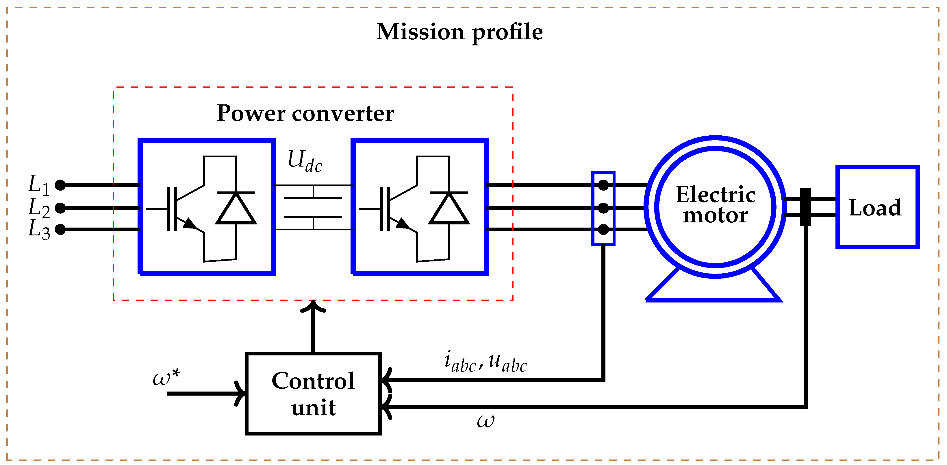


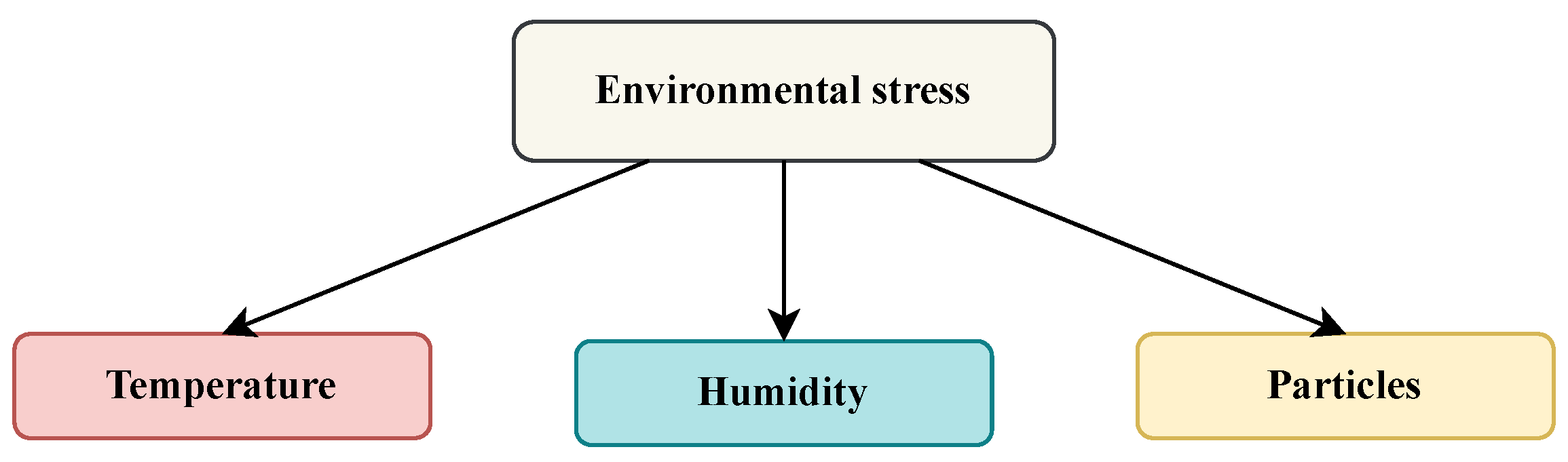
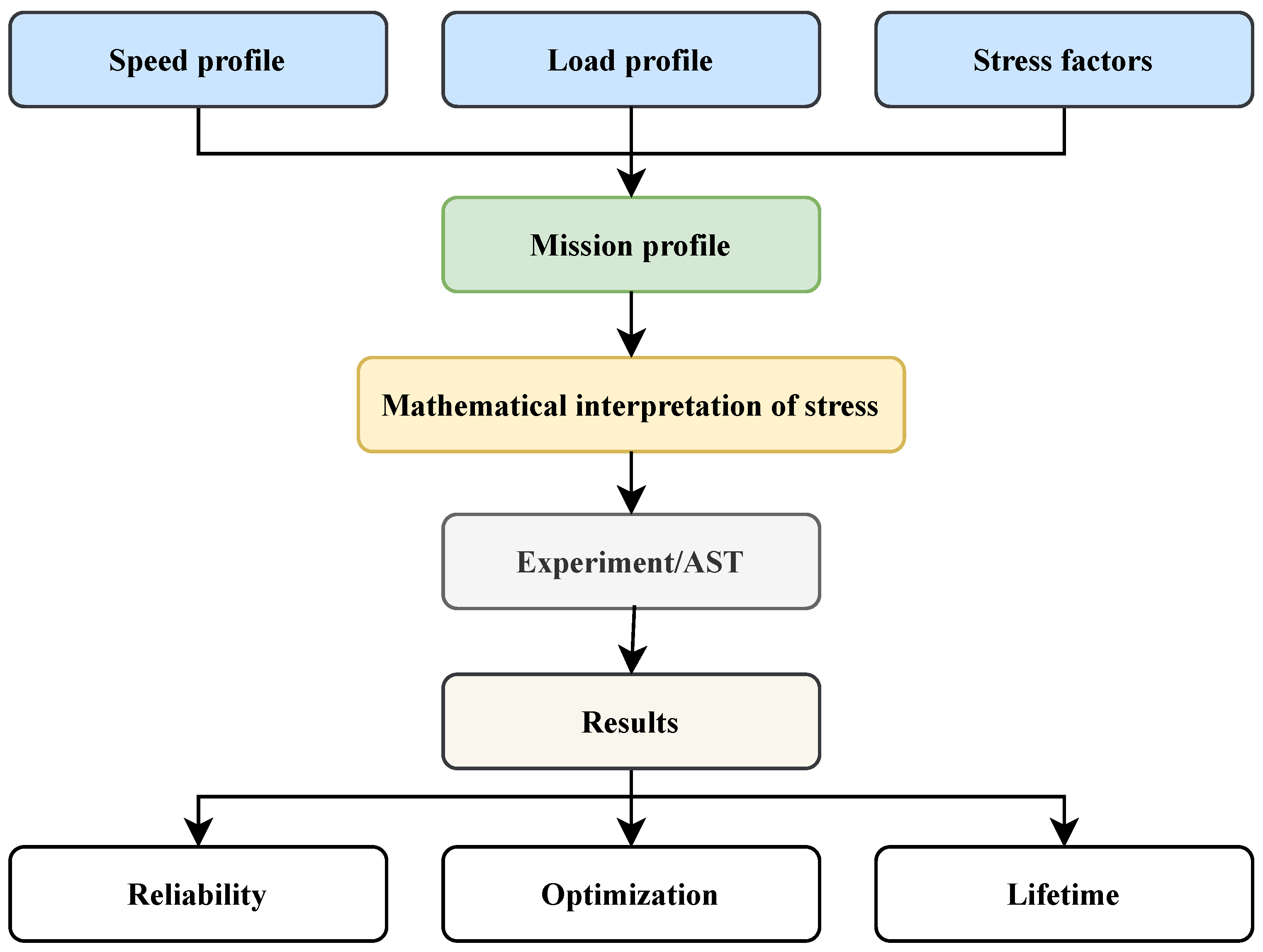


