1. Introduction
Traditional storage media are unable to meet the large-scale storage demands brought about by the rapid growth of global data [
1,
2,
3]. Synthetic DNA has emerged as a promising archival storage medium due to its ultra-high storage density, long-term stability, and low energy and maintenance costs [
4,
5,
6]. In large-scale parallel synthesis, the synthesis of DNA remains limited to relatively short sequences, typically less than 300 nt [
7]. Therefore, most DNA storage systems employ a distributed strategy by fragmenting data into multiple sub-blocks, each encoded into separate DNA molecules [
8,
9]. For example, storing 1 TB of data may require approximately 30 billion unique DNA strands.
Efficient data retrieval from DNA storage relies on high-redundancy sequencing to ensure both accuracy and integrity. This process generates a large volume of sequencing reads through parallel outputs, posing substantial computational challenges that conventional architectures struggle to address [
10,
11,
12]. Moreover, traditional clustering and multiple sequence alignment (MSA) algorithms incur substantial computational costs in processing these massive sequencing reads [
13,
14,
15]. To facilitate sequence identification, each DNA strand is assigned a unique index sequence, which is often encoded with error correction codes (ECCs) to enhance robustness against errors [
16,
17,
18]. While ECC-based index decoding can alleviate complexity to some extent, the computational burden remains significant in large-scale storage scenarios. Therefore, achieving high-throughput and low-latency DNA data retrieval remains a critical challenge.
Traditional CPU-based architectures are increasingly inadequate for handling the intensive computational demands of DNA data readout. Heterogeneous computing has emerged as a promising paradigm that integrates multiple accelerators, such as CPU, GPU, and FPGA [
19,
20]. It overcomes the performance bottlenecks of single-processor architectures under high workloads [
21,
22,
23]. Recently, several studies have explored the use of heterogeneous computing for accelerating local sequence alignment and MSA in DNA readout. For example, Smith–Waterman (SW) alignment, known for its high computational complexity, has been implemented on FPGA for hardware acceleration [
24,
25]. A parallel processing model on CPU-GPU heterogeneous platforms has been proposed for MSA [
26,
27]. To facilitate large-scale DNA storage validation, an FPGA-based accelerator for edit-distance computation, along with a heterogeneous architecture simulation platform for DNA storage (DNA storage simulator, DNAssim), has been developed [
28,
29,
30]. However, existing work primarily focuses on accelerating individual tasks such as edit-distance computation and lacks an integrated hardware acceleration solution for the entire DNA readout pipeline.
We propose a novel FPGA-based heterogeneous computing architecture to address the computational challenges in short-fragment DNA data readout. The architecture accelerated critical DNA data readout tasks through a modular pipelined design. Primer sequence identification and an index check were implemented using combinational logic and staged pipelines, which improved sequence identification and clustering. A parallel majority voting module was introduced, along with a ping-pong-structured deinterleaver. An efficient LDPC decoder was integrated to enhance error correction, and multi-module task-level pipelining further boosted the throughput. To address the issue of non-continuous index values after encoding, a memory-efficient lookup structure was designed to reduce RAM usage. Compared to software-only solutions, the proposed architecture achieved significantly higher DNA data readout performance.
We evaluated the accelerated system on an Alveo U200 accelerator card. The experimental results showed that the proposed accelerated system achieved a speedup of two orders of magnitude under typical error rates (0.6%, 1%, and 1.5%). In a high-error, low-coverage scenario (error rate of 1.5% and coverage of 15×), the system reached a peak acceleration ratio of up to 373.1 times. For 4,989,600 DNA molecules with a total storage capacity of 59.4 MB, the proposed system achieved data readout in just 12.40 s.
2. DNA Data Storage Readout and Hardware Acceleration
Here, we provide an overview of the fundamental workflow of DNA data storage and review related work, focusing on clustering-based readout approaches and related hardware acceleration studies.
2.1. Fundamental Workflow of DNA Data Storage
The process of storing data in DNA consists of four main stages: encoding, DNA synthesis (data writing), high-throughput sequencing (data readout), and data recovery (
Figure 1). Data writing consists of the following steps. First, the raw data are encoded using a specific algorithm and mapped to a base sequence based on a predefined bit-to-base mapping scheme. Next, an index sequence is appended, and primer pairs are added to both ends. Finally, high-throughput DNA synthesis is employed to generate DNA strands carrying the encoded information.
The readout and data recovery process of DNA storage involves both biochemical operations of DNA samples and computational processing of sequencing reads [
31]. The biochemical operations primarily include polymerase chain reaction (PCR) amplification and high-throughput sequencing, which produce many sequencing reads. To efficiently process these data, primer sequences are first identified. Then, read grouping is performed based on the index sequences. Next, edit-distance-based multiple sequence alignment is performed. Finally, the consensus is reassembled into codewords and decoded to recover the original file.
This study focuses on accelerating the DNA storage readout process. Unlike prior studies that focus on optimizing clustering or multiple sequence alignment, we propose a comprehensive hardware acceleration approach for the full DNA data readout pipeline.
2.2. Clustering-Based Readout Method and Hardware Acceleration
To ensure the reliability and storage density of DNA data storage, various encoding and decoding methods have been proposed. Organick et al. [
10] introduced an encoding scheme based on Reed–Solomon (RS) codes. To enhance reliability, their method employs XOR operations to mix input data with a pseudo-random sequence, preventing repetitive bit patterns (e.g., consecutive ‘0’ or ‘1’). This approach reduces systematic errors in DNA synthesis and sequencing while lowering decoding complexity. During the conversion to base sequences, a rotating code is applied to eliminate homopolymers (e.g., “AAAA” or “GGGG”), minimizing sequencing errors. For data readout, a clustering-based approach is used to group erroneous sequencing reads into clusters corresponding to the original DNA sequences, facilitating large-scale sequencing data processing. Consensus sequences are then determined through majority voting to correct errors. However, the extensive similarity calculations in clustering and majority voting, combined with the high complexity of decoding long RS codes, impose substantial computational challenges.
To mitigate these issues, Grass et al. [
12] further proposed a concatenated RS coding scheme, where individual sequences are indexed, the outer code handles complete DNA strand loss, and the inner code corrects single-base errors. This method reorders sequences using unique index sequences, achieving DNA molecule identification with significantly lower complexity than clustering-based approaches. However, large-scale RS coding, complex data reordering, and index checking introduce substantial computational overhead. Moreover, index checking through lookup table mapping requires robust algorithms and hardware support, hindering its large-scale application in oligonucleotide pools and limiting its scalability.
To address the high computational complexity and prolonged simulation time in DNA storage verification, Marelli et al. [
28,
29,
30] developed DNAssim, a simulation framework integrating FPGA-based heterogeneous acceleration to enhance large-scale DNA data storage simulations. This framework focuses on edit-distance computation, a computationally intensive step in clustering algorithms. A dedicated FPGA accelerator, implemented on the Xilinx VC707 platform, was deeply integrated with a software simulation environment, forming a hybrid heterogeneous system. DNAssim supports the entire workflow, from data encoding and DNA sequence mapping to index addition, noise modeling, and decoding. It also enables the analysis of common DNA storage errors, such as insertions, deletions, substitutions, PCR noise, and sequencing biases. Specifically, for edit-distance computation, a parallel FPGA-based accelerator with 32 processing units was designed, enabling simultaneous calculations across multiple DNA sequence pairs. High-speed data transmission is achieved via a custom PCIe interface, leading to an 11-fold speedup in edit-distance computation compared to a software-only implementation and 5.5 times acceleration in clustering simulation, significantly reducing simulation time.
Using hardware to evaluate coding performance is a common approach [
32]. In our study, we explore how heterogeneous computing can be leveraged to accelerate DNA data readout and develop a hardware-accelerated processing core. This accelerator takes sequencing data as the input and performs primer sequence identification, index checking, majority voting, deinterleaving, and decoding in an end-to-end hardware-accelerated manner. A software layer performs real-time control of the hardware, optimizing the readout performance of the DNA storage system.
3. Proposed Encoding Method for DNA Data Storage
DNA storage faces challenges associated with complex error types and high error rates, including base insertions, deletions, and substitutions introduced during synthesis and sequencing, as well as sequence loss. Given the low error rate required for DNA storage, a key challenge is designing highly reliable coding schemes tailored to DNA storage to effectively address these diverse error types [
33,
34].
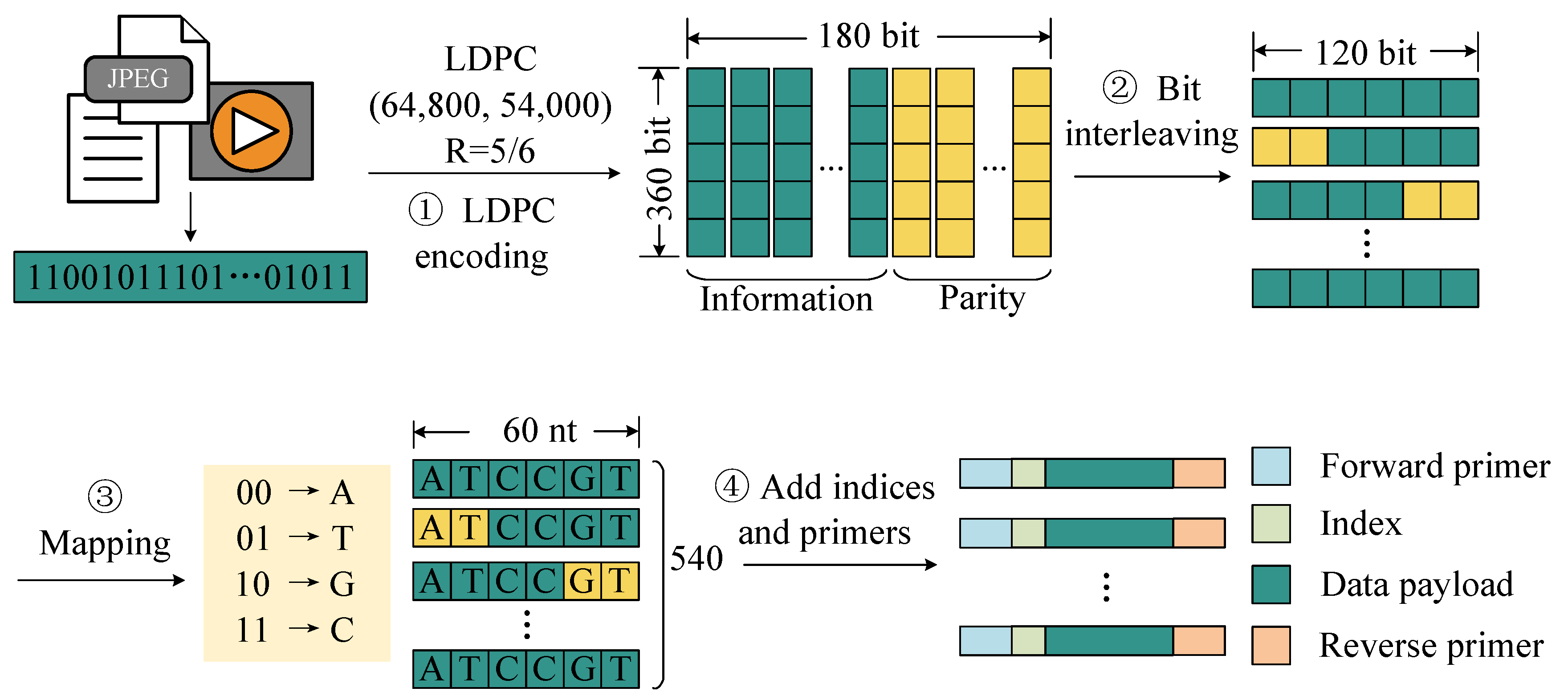
To address this challenge, we propose an encoding method optimized for hardware implementation. As shown in
Figure 2, this scheme consists of the following steps. First, the binary data to be stored are divided into fixed-length blocks, and each block is encoded with LDPC codes for error correction. This step enhances the robustness of the data against errors introduced during storage and readout. Then, an interleaving operation is applied to the encoded codewords to enhance resistance against burst errors caused by sequence loss during storage. By redistributing bits across different positions, this step improves the error correction capability of the code in handling consecutive errors. Then, the interleaved codewords are segmented and mapped into DNA sequences using the following base mapping rules: (00) → A, (01) → T, (10) → G, (11) → C. Furthermore, to facilitate the identification of sequencing reads during the recovery process, unique index sequences are added to both ends of each DNA sequence. Finally, primer pairs are added to both ends of the sequence.
Our proposed encoding scheme employs LDPC error correction, interleaving, and index optimization, providing an efficient and reliable encoding strategy for DNA data storage. Specifically, we employed the LDPC (64,800, 54,000) code and used a 360 × 180 interleaving matrix to interleave the encoded data. After interleaving, each LDPC codeword was grouped into 120 bits, which were mapped to 60 nucleotides, resulting in 540 sets of payload sequences. Using this encoding method, we encoded a total of 9240 LDPC codewords, resulting in 4,989,600 DNA sequences with a total storage capacity of 59.4 MB.
We designed a method that uses both primer and index sequences to distinguish different molecules. These large-scale DNA sequences were divided into 12 oligonucleotide pools corresponding to 12 primer pairs, with each oligonucleotide pool containing 415,800 oligonucleotide molecules. For each pool, a set of index sequences of 12 nucleotides was designed. The shortened Hamming code (24, 19) was used to encode a 19-bit binary number into 24 bits, which was then mapped to a 12 nt base sequence. In the generated index set, the first 415,800 index sequences with homopolymer lengths of less than or equal to 3 were used, and each DNA molecule was assigned a unique index.
4. The Proposed DNA Data Storage Readout Method Based on Heterogeneous Computing
In this section, we propose a heterogeneous computing architecture designed to accelerate DNA data readout, consisting of both software and hardware components. Specifically, we detail the architecture and operational workflow of the acceleration kernel within the hardware component.
4.1. Overall Design of Heterogeneous Acceleration Scheme
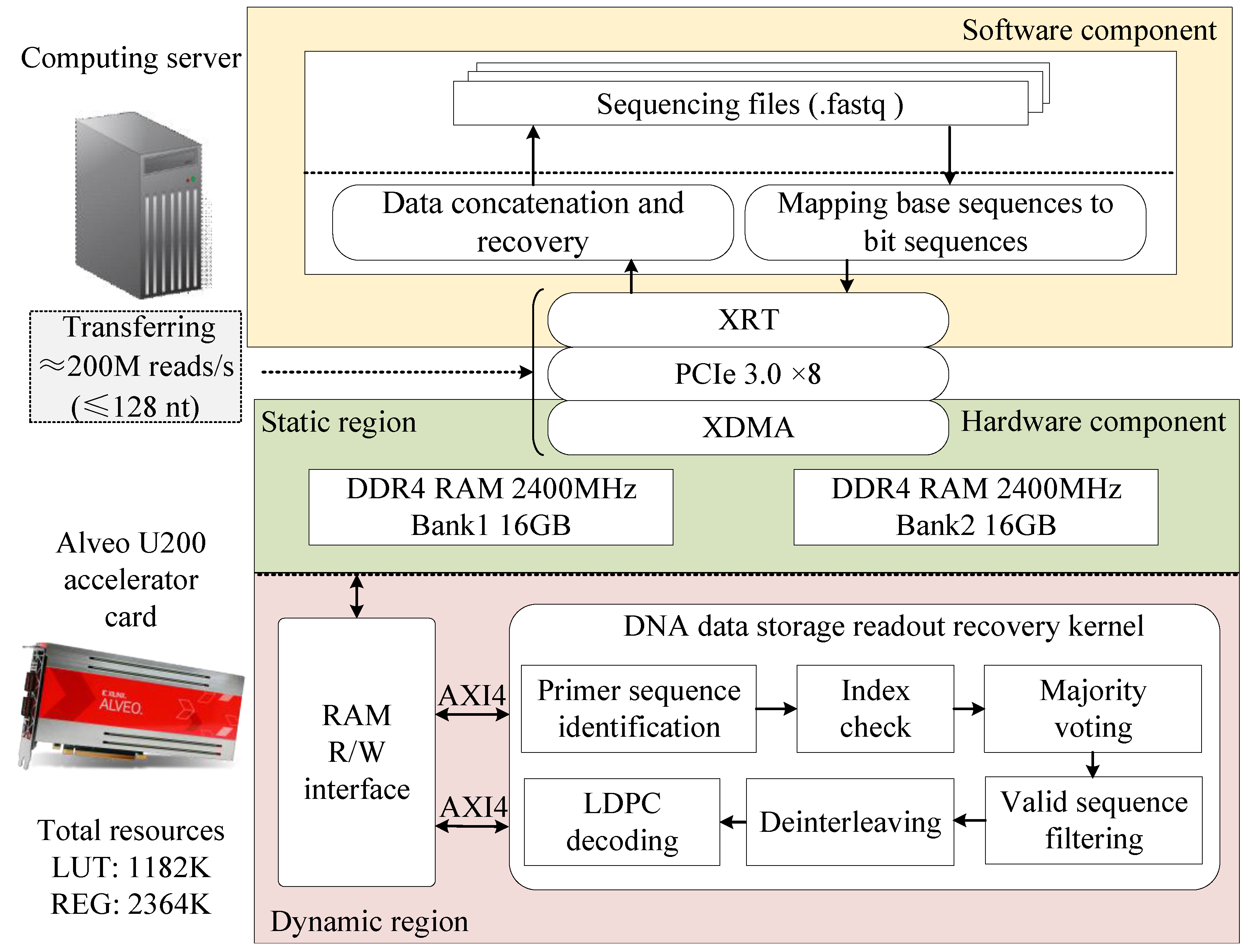
We proposed a heterogeneous-computing-based readout method for DNA data storage. The overall architecture of the proposed acceleration scheme is illustrated in
Figure 3, consisting of both software and hardware components. The software component runs on a general-purpose computing server with a CPU, developed in C++, and is responsible for processing sequencing data, managing data transmission to and from the off-chip DRAM, and controlling kernel execution. For the hardware implementation, we utilized the Alveo U200 data center accelerator, a high-performance FPGA featuring 64GB of DDR4 memory and a PCIe 3.0 interface. The hardware acceleration kernel was developed using an RTL-based design approach, incorporating a standard AXI interface. It was integrated with an x86 CPU in the host PC via the PCIe interface, forming a heterogeneous computing system.
Through the collaborative operation of the software and hardware components, the proposed method efficiently completes the entire process from sequencing data acquisition to original file reconstruction. Specifically, the workflow proceeds as follows. First, the software component converts the DNA sequencing data file (in FASTQ format) from a base sequence to a bit sequence. Then, it transfers the converted data to the off-chip DRAM of the hardware component via the PCIe interface while sending an enable signal to the acceleration kernel. Upon receiving this signal, the kernel executes six key steps: primer sequence identification, index checking, majority voting, deinterleaving, valid-sequence filtering, and LDPC decoding. Next, the sequencing data are restored to their original information sequence and stored in a designated location within the off-chip DRAM. Finally, the software component retrieves the restored information bit sequence from the off-chip DRAM of the accelerator, reassembles it, and reconstructs the original file.
4.2. Architecture of Hardware Acceleration Kernel
The FPGA-based DNA data readout hardware acceleration circuit was developed based on the proposed DNA storage encoding scheme. As illustrated in
Figure 4, the hardware kernel utilizes off-chip DRAM for storing intermediate results and employs a two-stage pipelined architecture to optimize the read process. The first stage focuses on primer sequence identification and index checking, supporting the parallel processing of two sequencing reads. In this stage, the sequencing reads are stored in DDR BANK1, while the payloads obtained after primer sequence identification and index checking are stored in DDR BANK2. The second pipeline stage encompasses majority voting, valid-sequence filtering, deinterleaving, and LDPC decoding, and saves the decoded result in DDR BANK1. The memory read and write channels of the two pipeline stages are separated, effectively preventing data congestion and significantly improving overall system efficiency.
The copy count memory is used to store the number of sequencing reads that have successfully identified the same reference. The copy count memory is constructed using BRAM resources with a design specification of 64 bits wide and 393,216 bits deep. Each 64-bit element is subdivided into 16 4-bit count cells, each with a maximum count limit of 15, allowing up to 15 sequencing read copies to be stored. This is sufficient for data recovery, as demonstrated by [
10].
In index sequence design, sequences with homopolymer lengths greater than three are excluded from the index, resulting in discontinuous index sequences in the synthesized DNA strands. A direct table lookup approach to map these discrete indices to a continuous index sequence would require excessive storage resources. To address this, we stored the identified data payload copies in memory in a dispersed manner according to their original indices. After majority voting, sequences corresponding to invalid indices are discarded. Compared to the direct-lookup-based index mapping method, the proposed approach significantly reduces BRAM resource consumption.The workflow of the DNA data storage acceleration kernel is as follows.
4.3. Hardware-Accelerated Kernel Workflow
The execution of the hardware-accelerated kernel for DNA storage readout and recovery proceeds as follows.
Step 1: Upon receiving the start signal from the host, the acceleration kernel simultaneously reads two sequencing reads from the off-chip memory. Each read is 224 bits long and is aligned to 256 bits for merging into a 512-bit-wide transmission. The sequencing reads are stored in a data buffer for subsequent module access. Each raw sequencing read consists of a 40-bit forward primer sequence, a 24-bit index sequence, a 120-bit data payload, and a 40-bit reverse primer sequence.
Step 2: Each 512-bit-wide dual-read sequencing data group is split into two independent 256-bit signals, which are then fed into two separate primer identification modules. Each primer identification module is cascaded with an index check module, forming two parallel pipelined processing paths. The output of the primer identification module includes a 4-bit primer ID, the index sequence, the 120-bit data payload, and a 1-bit validity signal, which are passed to the index verification module. This module calculates the syndrome and preserves the information bits, ultimately outputting a 19-bit index information field, a 120-bit data payload, and a 1-bit validity signal.
Step 3: Based on the identified primer ID and the index information bits, the corresponding position in the copy count memory is incremented. The memory write interface stores the data payload in the designated location in the off-chip memory.
Step 4: Once all valid data payloads have been written to memory, the majority voting process begins. The data payloads are aligned to 128-bit widths and concatenated into 512-bit-wide blocks, which are sequentially read from off-chip memory BANK2. The majority voting module produces a 120-bit consensus sequence, a 120-bit erasure flag sequence, and a 1-bit validity signal.
Step 5: The 1-bit validity signal output from the majority voting module serves as the input to the valid-sequence filtering module. A table lookup is performed to retain only the consensus and erasure flag sequences associated with valid indices, where the homopolymer lengths meet the predefined requirements.
Step 6: Two deinterleaving modules operate in parallel to process the consensus sequences and erasure flag sequences, producing two 360-bit-wide output signals that serve as inputs to the LDPC decoding module. The LDPC decoder performs error-and-erasure correction on codewords that still contain substitution and erasure errors to recover the original data. The 360-bit output signals from the LDPC decoder are then aligned to a width of 512 bits and sequentially written to the designated result storage region in off-chip memory BANK1. This completes the entire DNA storage readout and recovery process within the kernel.
5. Modules of Hardware Acceleration Kernel
We present a detailed analysis of the working pipeline and implementation effects of the key modules within the kernel, including the primer sequence identification, index check, majority voting, valid-sequence filtering, deinterleaver, and LDPC decoding modules.
5.1. Primer Sequence Identification Module
The primer sequence identification module precisely identifies the forward primer sequences at the beginning of each read based on Hamming distance calculations. The primer sequence identification module consists of multiple Hamming distance calculation units, a multi-level comparison network, a reverse complement calculation unit, and a splitting unit (
Figure 5). When the 256-bit sequencing reads are output from the FIFO and enter the module, the splitting unit extracts the 40-bit forward primer sequence and the 144-bit index and payload sequence.
The Hamming distance calculation unit consists of a logic gate array and a parallel adder tree, enabling the parallel computation of Hamming distances between the input forward primers and 12 reference primers within a single clock cycle. The multi-level comparison network, implemented with 23 comparators, identifies the minimum value among 24 Hamming distances through a step-by-step comparison process and outputs the corresponding reference primer ID. A comparator checks whether the minimum Hamming distance meets a preset threshold and outputs a 1-bit validity signal. The reverse complement unit control signal, derived from a modulo-2 operation on the 4-bit primer ID, indicates whether the sequencing read corresponds to the reverse strand. It determines whether the original sequence or the reverse complement of the index and payload sequences is output through the dual path selector.
The proposed primer sequence identification architecture utilizes multiple parallel combinational logic units. These units operate in a pipeline manner, delivering high processing throughput while maintaining identification accuracy.
5.2. Index Check Module
The index check module includes a syndrome calculation unit implemented in combinational logic. This module performs a Hamming code syndrome check on the index sequences, retaining DNA strands that pass the verification and discarding those that fail.
A shortened systematic Hamming code (24, 19) is implemented as the error correction scheme (
Figure 6). The received codeword vector
is stored in a register, where
e represents the error vector. The decoder employs a syndrome-based error detection algorithm, computed as
. The syndrome is computed by a parallel logic circuit. When both the computed result and the valid input signal are asserted, the valid output signal is asserted through an AND gate.
5.3. Majority Voting Module
A dedicated hardware circuit module was designed to implement the majority voting process (
Figure 7). The module includes majority voting units, copy count memory, FSM, and a bit concatenation/splitting unit, enabling the processing of four sequencing read replicas per clock cycle. The 512-bit input signal, which contains 4 copies, is divided into four groups of 120 single-bit signals by the bit concatenation/splitting unit. The module features 120 majority voting units, enabling the parallel processing of 120 bits of payload. The input signal
corresponds to the
i-th bit of the
l-th sequencing copy from the
n-th reference sequence. The number of occurrences of bit ‘1’ in
l copies is calculated using a parallel adder tree, and the result is accumulated and stored in Reg_1. Every four cycles of valid input signals constitutes a complete round of majority voting, and Reg_1 is updated to reflect the total count of bit ‘1’ occurrences in all of the copies at that position. The value in Reg_1 is left-shifted by one bit (
) and compared with the copy count (
) stored in Reg_2. If
exceeds
, the output
is set to ‘1’; otherwise, it is set to ‘0’.
At the start of each new voting cycle, the FSM controls a multiplexer to right-shift Reg_3 by 4 bits and store the result, while the lower 4 bits of Reg_3 are saved to Reg_2. After 16 voting cycles, the RAM read address is updated, and the FSM controls the multiplexer to save the output from the RAM to Reg_3.
The erasure mark is computed during the fourth cycle of the voting process, with two distinct scenarios considered. The first scenario occurs when a value of ‘0’ is stored in Reg_2, indicating the absence of sequencing read copies for the current reference sequence. The second scenario arises when the number of bit ‘0’ and bit ‘1’ occurrences are equal ( = ). In both of these cases, the bit is set to ‘1’, marking it as an erasure error.
The majority voting module merges these erroneous sequence copies by counting the number of occurrences of ‘0’ and ‘1’ bits at the same position to determine the consensus sequence. Positions where the ratio of ‘0’ and ‘1’ bits is equal are marked as erasure errors. In addition, if there is no copy of the sequencing read corresponding to a certain primer ID and index, the entire sequence is marked as containing 120 erasure errors.
5.4. Valid-Sequence Filtering Module
Due to the removal of homopolymer sequences measuring longer than three bases during index design, the data payload stored in the off-chip DRAM exhibits discontinuities. The resulting consensus sequences contain invalid data. To address this, we employ a valid-sequence filtering module to remove invalid data. The hardware structure of this module is shown in
Figure 8 and includes a RAM address counter and RAM. The RAM has a depth of
and a width of 1 bit. The valid signals of the consensus sequence are counted upwards to generate the RAM read address. If the current data are invalid, the RAM outputs ‘0’; otherwise, the RAM outputs ‘1’. This module occupies only 16 BRAM resources, which is a significant resource saving compared to storing the entire index mapping table.
5.5. Deinterleaver Module
The deinterleaver module restores the original codeword order by applying row–column deinterleaving to the consensus sequence and erasure marker sequence. The module employs a dual RAM partition ping-pong architecture, as shown in
Figure 9. It utilizes two RAM units, each with a depth of 64,800 and a width of 1 bit, to construct a 180-row × 360-column interleaved matrix. The workflow of the deinterleaver module is as follows. Taking the 120-bit-wide consensus sequence deinterleaving as an example, the consensus is first converted from parallel to serial and written column-wise to partition A of RAM. Then, after partition A is filled with 64,800 bits, the consensus is written column-wise to partition B of RAM, while partition A reads out the data row-wise with a width of 8 bits. Finally, the codeword data are reassembled by a serial-to-parallel conversion unit into a 360-bit-wide parallel output.
5.6. LDPC Decoding Module
In the accelerator, the LDPC decoder is responsible for correcting the remaining substitution and erasure errors in the codeword [
35,
36]. The module is based on a partially parallel hierarchical implementation of the normalized min-sum algorithm (NMSA) [
37,
38,
39,
40]. The iteration strategy of this algorithm comprises a serial iteration strategy between each group and a parallel iteration strategy within the group, which enables faster convergence of iterative decoding [
41,
42]. The LDPC decoder module consists of four main components, including the check node unit, the variable node unit, the intermediate variable storage module, and the memory read/write address control module. The intermediate variable storage module contains the log-likelihood ratio (LLR) memory, the check node update RAM, and the variable node update RAM, all of which are implemented using dual-port Block RAM (
Figure 10).
Specifically, the LLR input and LLR_RAM are quantized using fixed-point fractional quantization with 1 bit for the sign, 1 bit for the integer part, and 3 decimal bits, while the data bit width transmitted between nodes is 7 bits. Therefore, the LDPC decoder module achieves rate compatibility and reduces the complexity of hardware implementation and the consumption of hardware resources while maintaining high performance.
6. Experimental Results and Analysis
In this section, we analyze the implementation results of the proposed design, providing a comprehensive evaluation in terms of performance, acceleration effectiveness, resource utilization, and power consumption.
6.1. Analysis of Primer Sequence Identification and Index Check
To evaluate the effectiveness of the proposed primer sequence identification and index check method, multiple tests were conducted under varying base error rates. Index sequences were verified using parity check relations (by computing the syndrome), and reads that failed the verification were discarded (
Figure 11).
An index was considered successfully verified if it passed the parity check, enabling identification of the corresponding original index and the subsequent clustering of associated sequencing reads. Approximately 1% of reads were assigned to the wrong index cluster despite passing the parity check.
Although the proposed index check strategy excluded a relatively large number of sequencing reads, it significantly reduced the probability of index crosstalk. This trade-off enhanced the overall reliability of read clustering, particularly in instances where there were sequencing errors.
6.2. Readout Performance Analysis
To further evaluate the capability of the proposed heterogeneous acceleration system for DNA data storage, we performed recovery tests under varying error rates and sequencing coverages. First, the hardware acceleration platform was built using a data-center-grade FPGA, specifically, an Alveo U200 series card. Host-side development was carried out using the Vitis unified software platform. The host server was equipped with an Intel Xeon® Gold 5220R CPU (2.2 GHz) featuring 96 cores and 256 GB of memory.
Then, a channel simulation model was developed to emulate sequencing data with varying error rates. The model incorporated insertion, deletion, and substitution errors (, respectively) to reflect common sequencing noise. It also included an average coverage parameter to model sequencing depth. The number of DNA molecule copies generated during sequencing was simulated using a Poisson distribution. A mutation probability was defined to represent the overall error intensity.
Figure 12 illustrates the data recovery performance under realistic conditions based on the proposed channel simulation model. Multiple datasets were generated using random input data under varying coverage and error scenarios. At a fixed coverage of 15×, four base error rates (1.2%, 1.5%, 1.8%, and 2.1%) were simulated. When the error rate was below 1.5%, the codeword error rate after majority voting remained within the error-correction capability of the LDPC decoder. However, at 1.8%, the codeword error rate increased to 1.9%, exceeding the correction limit and resulting in decoding failure. Additionally, at a 1% error rate, recovery was tested at coverages of 7×, 8×, 9×, and 10×. As the coverage increased to 9×, the codeword error rate decreased to within the correctable range.
Figure 13 shows the performance of the proposed heterogeneous computing system against a pure software implementation. Under average sequencing coverages of 15× and 25×, 100 independent experiments were conducted for both implementations across varying error rates. The experimental results show that error-free recovery was achieved at 15× coverage under a maximum base error rate of 1.5%, and at 25× coverage under a maximum base error rate of 2%. Furthermore, the hardware-accelerated heterogeneous solution exhibited readout performance comparable to that of its software counterpart. These findings confirmed the effectiveness and reliability of the proposed system under typical sequencing error conditions.
Figure 14 shows the impact of increasing sequencing coverage under a fixed base error rate of 1%. The results indicate that, at this error rate, the proposed heterogeneous platform could achieve error-free data recovery with a minimum coverage of 10×. To further verify the performance of the proposed heterogeneous system in the second-generation high-throughput sequencing scenario, we generated simulation data according to the Illumina sequencing error rate reported by Organick et al. [
10]. The results demonstrate that, under this realistic error model, the proposed system can still achieve error-free recovery with a minimum coverage of 8×. This indicates its effectiveness in handling typical errors in second-generation high-throughput DNA sequencing. Moreover, the readout reliability provided by the hardware-accelerated design is comparable to that of the software implementation.
6.3. Acceleration Performance Comparison with Software Method
To verify the acceleration performance of the heterogeneous computing acceleration kernels, a comparison of the runtime was conducted against a CPU-only software implementation using a series of sequencing datasets. The kernel operated at a clock frequency of 180 MHz, with its execution time measured on the host side by capturing the wall-clock time immediately before and after execution. The software implementation was executed on the host server CPU under the same test conditions.
The test dataset consisted of sequencing reads generated from 12 oligo pools, each containing 415,800 DNA sequences, resulting in a total of 4,989,600 reference sequences. Recovery tests were performed under three error rates (0.6%, 1%, and 1.5%) and three coverages (10×, 20×, and 25×). These combinations of error rate and coverage had been previously verified to support successful recovery and were used here to compare execution speed.
As shown in
Table 1, the accelerated system consistently achieved a speedup of two orders of magnitude over the software baseline across all test conditions, with even higher gains under high error rates. A peak speedup of up to 373.1 times was achieved under a high error rate (1.5%) and low sequencing coverage (15×).
When the error rate was kept constant, increasing sequencing coverage reduced the runtime of the CPU implementation but increased that of the FPGA. This divergence resulted from different system bottlenecks: the CPU runtime was dominated by LDPC decoding iterations, while FPGA performance was constrained by external memory write latency during index checking. Under fixed sequencing coverage, the FPGA kernel execution time decreased slightly as the base error rate increased. This was mainly because higher error rates led to more sequences being discarded during primer sequence identification and index checking, thereby reducing external memory access overhead. In contrast, the CPU execution time increased significantly with rising error rates, primarily due to higher codeword error rates, which resulted in more LDPC decoding iterations.
It is also important to compare the current implementation with previous works. DNAssim [
28] serves as a representative work in the field of hardware acceleration for DNA data storage. Therefore, we compare the work in this paper with DNAssim in
Table 2. Unlike previous studies, our heterogeneous acceleration platform targets the complete DNA readout pipeline. Due to the use of different algorithms and datasets, the number of sequencing reads processed per second is used as a metric to evaluate the processing speed of each solution. This comparison demonstrates that our method can process over 6 million reads per second, significantly outperforming DNAssim.
6.4. Resource Utilization and Power Consumption Analysis
The resource utilization of each functional module in the hardware-accelerated kernel for DNA storage readout is summarized in
Table 3. The LDPC decoder module was configured with 5-bit quantized inputs for log-likelihood ratios (LLRs), 7-bit storage for each check node, and a parallelism factor of 360. This module accounted for approximately 85% of the total logic resource, primarily due to the partially layered, parallel iterative decoding architecture. The copy count memory consumed 31.6% of the on-chip block RAM, as it stored sequencing copy counts for 12 oligo pools, each mapped to a distinct memory address range. In addition to the main processing modules, a considerable portion of hardware resources were also consumed by inter-module streaming interfaces and external memory read/write controllers. These components are essential to support high-throughput data movement and ensure efficient pipelining across functional stages in the decoding workflow.
Power estimates were obtained using the integrated Power Analysis and Optimization tool in Xilinx Vivado Design Suite 2022.1 at the post-implementation stage. At a clock frequency of 180 MHz, the total on-chip power consumption of the FPGA kernel was estimated to be 7.39 W, comprising 2.55 W of static power and 4.84 W of dynamic power. For the CPU, power consumption was measured by recording the average power during idle time and during software execution and calculating the difference between the two. Based on the time required to process the same 50 million reads, the energy consumption of the CPU and FPGA was estimated. As shown in
Table 4, the comparison demonstrates that the proposed FPGA-based system achieves a significantly lower energy cost.
7. Conclusions
We present a hardware-accelerated DNA data readout architecture based on heterogeneous computing. To address the challenges of large-scale DNA data storage, particularly the high complexity of readout recovery and the vast number of sequencing reads, we propose a multistage pipelined primer sequence identification and index check module implemented in hardware to achieve high data throughput. Our design features a parallel hardware architecture for majority voting and error correction decoding, ensuring efficient and reliable data processing. Additionally, we optimized the deinterleaver module using a ping-pong structure, further enhancing the throughput and overall system performance. The performance of the system was evaluated using simulated sequencing datasets with varying error rates and coverages. The results showed a peak speedup of up to 373.1 times, allowing 59.4 MB of stored data to be read in 12.40 s. These results demonstrate the potential of the proposed architecture for large-scale DNA data storage applications.
Future work will focus on extending the system to support multi-core and multi-board concurrency for the efficient scheduling and processing of multiple readout tasks. The current hardware kernel successfully processed a single data block containing approximately 59.4 MB of valid payload, demonstrating the scalability of the proposed design. For future scaling to larger datasets, the entire data stream can be partitioned into multiple independent blocks of this size. Since each data block can be processed independently, parallel execution can be achieved by distributing the sequencing data across multiple FPGA boards and scheduling concurrent kernel instances on each board. This strategy will significantly improve the throughput of the proposed system when deployed in large-scale DNA storage scenarios.


 ,
, 


