Featured Application
Hydrogen-battery hybrid robotic platform for rough terrain.
Abstract
This work presents the electro-mechanical design, physical implementation, and experimental testing of an intermediate-sized mobile robotic platform, Hygrobot, which is powered by the hybridization of a PEMFC fuel cell and LiPo batteries. Future mobile robots are anticipated to require sustainable and cost-effective energy solutions to increase their working time and adhere to ecological guidelines. Although substantial advancements have been achieved in creating marketable mobile robot designs, including improvements to their physical composition, sensory systems, navigation algorithms, and operational management, their widespread integration is still hindered. This obstacle is mainly attributable to the lack of robust power systems capable of functioning in varied and often unpredictable settings. Hydrogen, as an energy carrier, offers a promising solution to overcome these obstacles. Experimental tests reveal that the Hygrobot platform can achieve a linear speed of 17 km/h, a continuous operating time of over 8 h, and power consumption below 324 WA. Its mechanical design means that Hygrobot is able to overcome obstacles, facilitating movement in the three XYZ axes, and can perform tasks over rough terrain efficiently.
1. Introduction
From logistics and transportation to healthcare and agriculture, ground-mobile robots have enabled greater task efficiency, reduced costs, and improved safety. Thanks to advances in instrumentation and increased sensoristic capabilities, these systems can now perform complex tasks, adapt to changing environments and collaborate with humans more seamlessly, transforming the way that businesses and societies operate [1].
Regarding the next generation of mobile robots, these devices are expected to utilize eco-friendly and economical power sources to extend their operational duration and meet environmental standards, enabling their use in various sectors. While significant progress has been made in developing commercially viable solutions for mobile robots in terms of their physical structure, sensory capabilities, movement planning, and operational control, their widespread adoption remains constrained due to the lack of efficient power systems for use in diverse environments [2,3]. This limitation is primarily due to the scarcity of efficient energy systems suitable for use in hostile environments. For example, battery-based power systems for ground robotic platforms present significant challenges in terms of off-road applications. One of the primary limitations is the relatively low energy density, which restricts the range and operational endurance of these vehicles [4]. In off-road scenarios, where robots often traverse rugged terrain or perform prolonged tasks in remote areas, the energy constraints of battery-powered systems become more pronounced, requiring frequent recharging or battery swapping, which can disrupt operations. Additionally, the weight of batteries, which directly correlates with their energy storage capacity, impacts the overall performance of the robotic platform. Heavier batteries reduce manoeuvrability, making it more difficult for robots to navigate challenging landscapes. This weight penalty also limits the payload capacity [5]. Furthermore, battery performance can degrade rapidly in extreme temperatures [6]. As a result, there is a pressing need for research into higher-density energy storage solutions and innovative designs to optimize the energy-to-weight ratio of robotic systems.
In this new scenario, hydrogen-based hybrid power systems are explored as potential solutions to extend operational time and improve the overall robustness of off-road robotics [7,8]. Hybrid solutions should meet eco-friendly requirements: zero-emission operation, avoiding NOx, CO, HC, SOx, and CO2 toxic emissions, reduced noise levels, limited thermal signatures, and extended operating time. Additionally, power systems that combine fuel cells and batteries provide the benefits of both energy storage technologies, taking advantage of the bi-directionality of the batteries, their rapid response, and their high power density, while the fuel cell provides a high energy density that helps to reduce the overall weight of the system and significantly increase its range; at the same time, endurance is doubled (≥8 h) in comparison with battery-based systems [9].
This paper describes the design, manufacturing, and testing of a ground robotic platform powered by a hybrid power system consisting of LiPo batteries [10] and a proton exchange membrane (PEM) fuel cell [8]. Among its main features is an innovative traction system, with six independent drive wheels that maintain maximum ground contact at all times. The integration of a LiPo battery with a PEM fuel cell allows the system to respond to sudden changes in power demand. The LiPo battery was selected over other battery types due to its high power density (≥98% charge–discharge efficiency) and its ability to operate across a wide state-of-charge range (20–100% SOC). The PEM fuel cell was preferred over other fuel cell types because of its quick start-up, low operating temperature (~80 °C), and superior power-to-volume ratio—critical features for vessels operating on short routes with frequent port stops.
The paper assesses the technical feasibility and advantages of using a hybrid power system based on fuel cells and batteries for multiple applications in ground mobile robotics, increasing autonomy and reducing charging time compared to commercial models in the sector such as Ibericadron XAG R150 V2 [11], Milodón M50 [12], or RB-Vogui [13]. Table 1 shows the design requirements for the target robotic platform.

Table 1.
Design requirements for the Hygrobot platform.
The paper structure is as follows: Section 2 describes the mechanical design and its structural implementation. Section 3 covers the main issues covered in the electrical design, sizing, and component selection of the hydrogen–battery hybrid power system. Section 4 explains the methodology used in monitoring and movement control of the platform. Section 5 shows the tests carried out to verify the design, dimensioning, and operability of the platform. Finally, Section 6 and Section 7 discuss and offer conclusions on, respectively, the main results and features displayed by the platform, its strengths and weaknesses, and its position in relation to commercial models.
2. Mechanical Design and Structural Implementation
For the mechanical and structural design, the main challenge was to obtain a robotic platform capable of driving with enough stability over rough terrain, according to the requirements set out in Table 1. As the platform is designed for rough terrain, its structure must take into account the different parameters that affect the drivetrain power requirements and the general motion system design of the platform (terrain, platform weight, tyre pressure, wheel diameter, and suspension type [15]). In a previous study [16], it was concluded that the most important determining factor for calculating the rolling resistance coefficient (RRC) is the terrain. Table 2 compiles the general values of RRC depending on the terrain used, as shown in Figure 1.
Table 2.
Rolling resistance coefficient (RRC) values for different terrains.
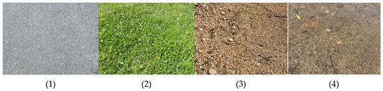
Figure 1.
Different operating terrains. From left to right: (1) bituminous material, (2) grass, (3) gravel, and (4) mud.
Once the possible ground conditions have been determined, it is necessary to define the design of the drivetrain to be used. Some of the possible options are front two-wheel drive (FWD), rear two-wheel drive (RWD), or all-wheel drive (AWD). In our case, the AWD option has been chosen to increase the traction of the robotic platform, using an arrangement with six independent drive wheels. This will guarantee maximum contact with the ground, providing greater traction to the platform for use on rough and difficult-to-navigate terrain. Figure 2 shows a 3D image of the design proposed by the authors.
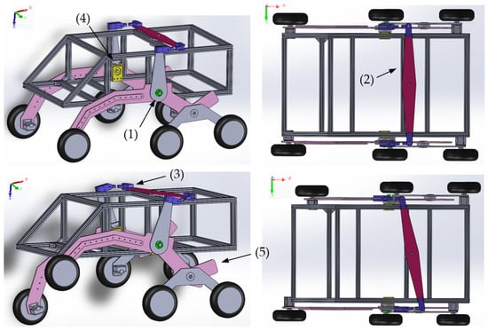
Figure 2.
The 3D design of Hygrobot. Detail of movement range for overcoming obstacles: (1) ZX pivot points, (2) differential bar, (3) joint-based connection system, (4) YX pivot points, and (5) ZX arm for connecting the three X-axis-aligned wheels.
The proposed design has dimensions of 800 mm × 500 mm × 630 mm (length—X axis, width—Y axis, and height—Z axis) and weighs approximately 20 kg (empty platform). The use of two pivot joints ((1) in green, Figure 2) on each side of the platform chassis allows the wheels to move freely in the ZX plane. The distance from point (1) to the ground is 27 cm; this allows Hygrobot to cross puddles of water without incurring risk to its operation. The differential bar ((2) in red) located at the top of the platform ensures that the effort exerted on these wheels during movement is compensated by the rest of the wheels. This differential bar is formed by a 6-millimetre-thick rhomboid-shaped plate, which is attached to two vertical arms fixed on each side of the moving parts of the chassis. Since the pendulum motion of the vertical arms not only generates movement along the X-axis but also along the Y-axis, a joint-based connection system ((3) in blue) has been included.
To achieve the pivoting connection needed in the YX plane between the differential bar and the upper chassis, a new piece ((4) in yellow) has been designed that is fixed to the aluminium modular profiles and houses 2 bearings and an M8 bolt, minimizing friction and ensuring a secure connection with the structure. The central part of the structure is designed to house the power system components (described in Section 3). It is built in a modular way, using 20 mm × 20 mm aluminium profiles and “V” threaded connections.
Finally, the chassis that connects the wheels to the central structure consists of two pieces of 6.0 mm thick aluminium sheet ((5) in pink), joined together by a system of axial and radial bearings that allow movement along the XZ axis.
The central structure of the platform, which houses the propulsion and control systems, was built from modular aluminium profiles with a section of 20 mm × 20 mm, as Figure 3a shows. The moving parts were machined using a 6-millimeter-thick 5754 H111 aluminium sheet as the raw material (see Figure 3b).
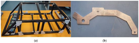
Figure 3.
(a) Central structure of the platform. (b) Moving part of the platform.
The equipment used for machining was a 3-axis machine-type computer numerical control (CNC) (Lagun Machinery S.L, Alava, Spain), model Lagun 1000, with a Fagor 8050 processor (see Figure 4). The parts that serve as housing for the bearings and shafts ((4) in Figure 2) connecting the moving parts of the chassis with the fixed parts (central casing) were also machined from 5754 H111 aluminium, due to the high stresses they must withstand without deforming.
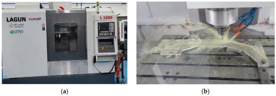
Figure 4.
(a) CNC machine, the Lagun 1000. (b) Detail of the machining process of a mobile part.
For the fabrication of the shaft that connects the moving parts of the chassis and allows the movement of the wheels in the ZX plane, a manual lathe was used, whereby M16 stainless steel screws were machined down to a diameter of 15 mm in 0.2 mm increments. The screw heads were also turned, reducing their diameter and thickness, and self-locking nuts were used to create a secure fastening system, as shown in Figure 5.
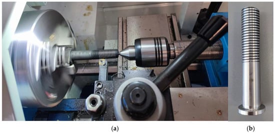
Figure 5.
(a) Detail of the turning of an M16 stainless steel screw on a manual lathe. (b) The final result.
Finally, the supporting parts that would hold the power system components and the external casing were printed in 3D, using PLA filament and epoxy resin.
3. Design and Sizing of the Hydrogen-Battery Hybrid Power System
The electrical power system was designed according to load requirements and primarily consists of six AC-powered wheels. DC/AC converters (Shenzhen Renhao Weiye Technology Electronics Co., Ltd., Donnguan, China) are used, operating at 36 VDC/wheel, with a current consumption ranging from 0 to 1.5 A/wheel (Figure 6).
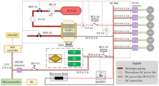
Figure 6.
Hydrogen-battery hybrid power system for the Hygrobot platform.
The hybrid electrical power system comprises a hydrogen-powered PEM fuel cell and a battery pack (B1, B2, B3), which together regulate the DC bus voltage, supply peak power demand for the wheels, and provide sufficient energy to last over the required 8 h of autonomy.
Both the PEM fuel cell and battery pack are connected directly to the DC bus with relays RLY-01 and RLY-02. This configuration avoids the use of heavy power electronics, mitigating excess weight on the mobile platform.
The PEM fuel cell subsystem is built from the PEM fuel cell and all the accessories needed for its operation (balance of plant, or BoP). It is monitored with voltage and current transductors, labelled VT-01 and CT-01. The hydrogen supply is controlled with the solenoid valve SOV-01 and the pressure regulator PR-01, which is connected to the output of the hydrogen tank. The flow transductor FT-01 provides details of the PEM fuel cell’s hydrogen consumption. A hydrogen purge is achieved with a solenoid valve, SOV-02. All the BoP’s accessories have been selected using the basis of a common 12 VDC operating voltage. From the battery subsystem output, a DC/DC converter is then needed to convert the 36 V received from the DC bus to the 12 V required by the BoP. The connection between the battery subsystem and the 36-to-12 V DC/DC converter is established by the interrupter INT-01.
The platform’s driving system is based on a 6-channel radio-controlled (RC) module (described in Section 4) that allows the user to move the vehicle in different directions and speeds. The radio control module communicates with the power converters of the wheels through the signal modulation carried out by the microcontroller.
Finally, a rheostatic braking system has been included on the platform, with the aim of dissipating the energy surplus that could eventually appear when the PEM fuel cell and battery subsystem are working together. The rheostatic brake is connected to the DC bus by means of a MOSFET transistor, controlled by the microcontroller, which can activate or deactivate the transistor, depending on the bus voltage.
Regarding the power balance, which is based on the direct connection of the PEM fuel cell subsystem and the battery subsystem with the DC bus, a passive power management system is implemented. The nominal battery subsystem voltage and PEM fuel cell subsystem can be expressed as = = 36 V. The battery voltage is monitored. In this case, its value is ; this means that the battery subsystem is overcharged. Then, the PEM fuel cell is disconnected, the rheostatic brakes are activated, and the battery subsystem provides the power demanded by Hygrobot. This will involve the battery subsystem discharges. In the case of , this means that the battery subsystem is over-discharged. Then, Hygrobot is stopped, and the PEM fuel cell recharges the battery subsystem. When , the PEM fuel cell and battery subsystems supply the power demanded by Hygrobot, Figure 7.
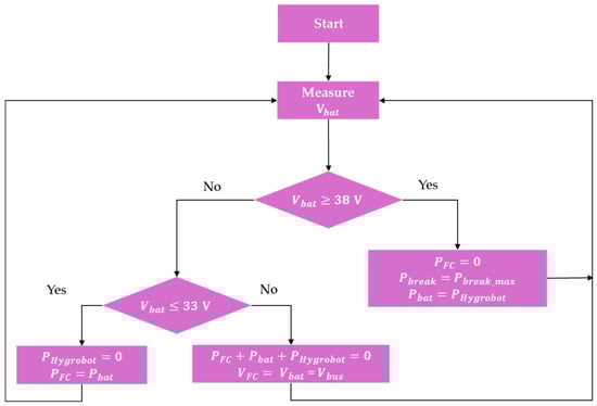
Figure 7.
Hygrobot power balance flowchart.
Each subsystem is described in detail in the following sections.
3.1. PEM Fuel Cell Subsystem
The fuel cell selected for this application was a refurbished model FCS-H2000 from Horizon, the main technical characteristics of which are shown in Table 3. For the PEM fuel cell to yield its best performance, a membrane rehydration protocol was applied. This consists of applying a membrane wetting protocol, as severe dehydration of the membrane leads to a drastic decrease in the fuel cell’s conductivity and, consequently, the power it can supply. For this purpose, Millipore water was passed through the anode channels until they were completely saturated. The fluid was then removed, and the fuel cell was left to dry for 24 h. After this period, the PEM fuel cell was cycled for 1-min intervals at 0–30 V. After 20 ON-OFF cycles, the PEM fuel cell had improved its performance by 40%, from 445 W to 627 W, as shown in Figure 8.
Table 3.
Technical characteristics of the PEM fuel cell FCS-H2000.
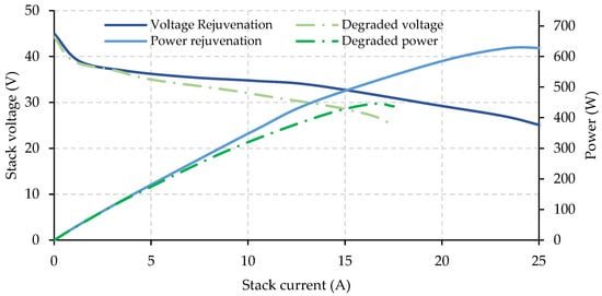
Figure 8.
PEM fuel cell performance characterization before and after the rejuvenation procedure.
3.2. Hydrogen Storage Sizing
Based on the platform dimensions, shown in Figure 2, and the design requirements, shown in Table 1, the authors selected a metal hydride tank [17], model MyH2-2000, sourced from H2Planet (technical data are shown in Figure 9 and Table 4). Its design and technical characteristics made it suitable for integration into the Hygrobot platform for operational testing.
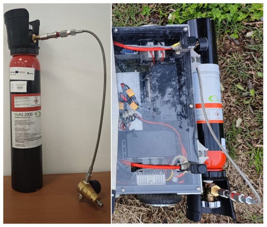
Figure 9.
Detail of the hydrogen tank MyH2-2000: (left) in the laboratory; (right) outdoors, on the Hygrobot platform.
Table 4.
Hydrogen tank MyH2-2000: technical characteristics.
To estimate the continuous operating time range, we should take into account the energy stored in the hydrogen tank (1), . For this calculation, it is necessary to know the hydrogen density, , at normal conditions of temperature and pressure (20 °C and 0.1 Mpa) [20] and the lower heating value [21]:
where:
is the energy stored in the form of hydrogen (J).
is the maximum hydrogen volume stored in the bottle (2000 dm3).
is the hydrogen density at 20 °C and 1 atm (0.089 g/dm3).
is the hydrogen’s lower heating value (120 MJ/kg).
This results in = 21.36 MJ. The electrical energy that the PEM fuel cell can supply with this tank,, is determined using the efficiency values shown in Table 3 with Equation (2):
where:
is the electrical energy delivered by the fuel cell (J).
is the fuel cell efficiency (40%).
This yields = 8.54 MJ. Then, the continuous operating time range of the fuel cell, , is calculated with Equation (3):
where:
is the continuous operating time of the PEM fuel cell (h).
is the fuel cell power when working at (170 W, see Figure 8).
This results in = 13.96 h.
3.3. Battery Subsystem
The battery subsystem is made up of three LiPo battery modules (B1, B2, and B3). Each module is composed of 10 cells with a nominal voltage of 3.6 V and a capacity of 2 Ah, with a discharge rate () of 1.5C and a 10s1p configuration. The three modules are connected in parallel, which triples the capacity of the battery subsystem ( 6 Ah) while maintaining a nominal voltage compatible with the DC bus voltage ( = = 36 V). Then, the energy stored in the battery subsystem can be identified using Equation (4):
where:
is the energy stored in the battery subsystem (Wh).
is the battery subsystem voltage (36 V).
is the capacity of the battery subsystem (6 Ah).
Equation (4) results in = 216 Wh.
Based on the energy stored in the battery, in order to calculate the continuous operating time range of the battery subsystem, it is necessary to determine the power that it must supply to the platform using Equation (5):
where:
is the power consumed by the Hygrobot platform (W).
is the power to be provided by the battery subsystem (W).
The power consumed by the Hygrobot platform can be determined using Equation (6):
where:
is the power consumed/wheel (W).
is the number of wheels (6).
is the power consumed by the BoP of the PEM fuel cell (W).
is the average power dissipated by the brakes (W).
The average power consumed by the wheel is calculated by considering half of the maximum current required by the wheel (maximum current 1.5 A/wheel) at 36 V, where = 0.75 A·36 V = 27 W. The BoP power consumption is obtained from = 0.5 A·36 V = 18 W, while for the rheostatic brake, an activation time of 2% of the platform duty cycle is assumed, resulting in = 6.4 W. This gives a result of = 186.4 W and = 16.4 W.
Then, the continuous operating time range of the battery subsystem, , is identified using Equation (7):
where:
is the continuous operating time of the battery subsystem (h).
is the battery subsystem voltage (36 V).
is the battery subsystem capacity (6 Ah).
This results in = 13.17 h.
Therefore, the battery and PEM fuel cell subsystems are designed to operate over the same number of hours.
Additionally, it should be checked that the maximum power that the hydrogen-battery hybrid power system can deliver is higher than the maximum power required by Hygrobot, .
Then, can be determined using Equation (8):
where:
is the maximum power/wheel ( = 1.5 A·36 V = 54 W).
Then, = 348.4 W
Conversely, the maximum power that the hydrogen–battery-based hybrid system can deliver is determined with Equation (9):
where:
is the maximum power provided by the hydrogen–battery hybrid system (W).
is the maximum power provided by the battery subsystem (W).
is kept at 170 W; the PEM fuel cell is working at .
The maximum power provided by the battery subsystem can be obtained using Equation (10):
where:
is the discharge rate of the batteries (1.5 C).
This results in = 324 W, and = 494 W.
Therefore, > .
Once the electrical sizing has been decided, in order to determine the battery subsystem configuration needed, a series of associated issues must be addressed. Although the three modules are the same commercial model, they can behave in an intrinsically different way, due to mismatches in the charging/discharging process. This phenomenon can cause voltage variations between the batteries, which could lead to a short circuit and the degradation/destruction of the batteries. To avoid this risk, a balancing circuit (battery management system, or BMS) has been designed to guarantee continuous balancing between modules, without the risk of high current energy transfer between them. This passive circuit is based on the use of operational amplifiers to detect voltage differences (on the order of millivolts) between the battery modules and, by switching transistors, dissipate the differential energy through the conduction of power resistors. The schematic of the designed circuit is shown in Figure 10.
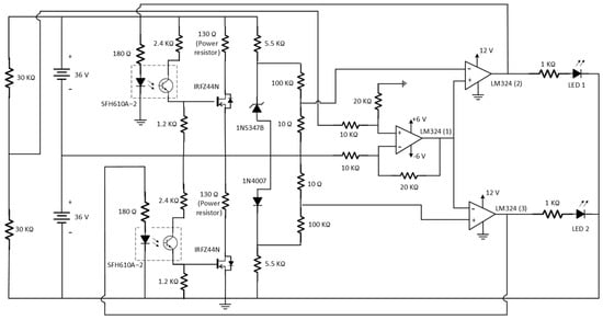
Figure 10.
The BMS designed for balancing the battery subsystem.
Then, if a battery module does not have the same voltage as its pair, the voltage difference (divided by two, due to the voltage divider) is driven into the operational amplifier LM324(1). This operational amplifier, in a differential configuration with gain = 2, isolates the battery subsystem from the balancing circuit and restores the voltage difference to its original value.
The output of the operational amplifier LM324(1) Is sent to the operational amplifiers LM324(2) and LM324(3) in an open-loop configuration to act as comparators. LM324(2) and LM324(3) compare the voltage difference between the two modules with a reference voltage value (in this case, it was designed so that the reference voltage is 10 mV). Since the comparator amplifiers are placed in opposite directions, one conducts if the signal is greater than +10 mV, while the other conducts if the signal is below −10 mV. When conducting, LED1 and LED2 light up to indicate that the corresponding battery module has a voltage higher than its pair, and transistor IRFZ4-4N is switched on, which activates a power resistor to dissipate energy until the voltage difference is smaller than ±10 mV.
3.4. Design of the Rheostatic Brake System
The rheostatic braking system ensures that excess energy is dissipated when the electric motors are braking. It consists of a dynamic braking system that uses the kinetic energy of a moving vehicle and converts it into electrical energy, which is then dissipated as heat through the resistors. In simpler terms, this system transforms the kinetic energy into heat, which, in turn, reduces the vehicle’s speed or decreases the battery subsystem state of charge (SoC).
The braking system was designed as shown in Figure 11, using a power resistor, a N-Channel MOSFET transistor, a voltage sensor VT-01, and a microcontroller (in this case, an Arduino Mega 2560 Pro (Adafruit Industries, New York, NY, USA) was used).
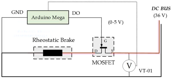
Figure 11.
Schematic of the rheostatic braking system used in the robotic platform.
To ensure good braking capacity, it was decided that the power of the rheostatic brake must be able to dissipate 100% of the power consumed by the motors in the most restrictive case ( = 324 W). Since the DC bus voltage, , is 36 V, it is then possible to calculate the equivalent resistance, , with Equation (11):
where:
is the rheostatic brake resistance (Ω).
is the DC bus voltage (36 V).
is the power to be consumed by the rheostatic brake (324 W).
This results in = 4 Ω.
The resistor was placed in front of the vehicle (to avoid introducing heat into the battery subsystem and the PEM fuel cell’s surrounding areas). Finally, the VT-01 sensor was designed with a high-resistance voltage divider configuration to minimize current losses. The voltage reduction ratio was 8, to convert the 36 V battery subsystem voltage to 4.5 V (since the microcontroller’s voltage reading range is 0–5 V).
Table 5 shows the commercial models of the elements used for the hydrogen–battery hybrid power system.
Table 5.
Fact data for those components that integrate the hydrogen–battery hybrid power system.
4. Movement and Navigation Control Subsystem
4.1. Integration, Control, and Testing of BLDC Wheels
From the rolling resistance values given in Table 2, the load to which the wheel motors will be subjected can be estimated using Equation (12):
where:
is the platform wheels’ resistance force (N).
is the rolling resistance coefficient (0.02 for bituminous).
is the gravitational attraction force due to the mass of the platform (637 N).
is the slope angle of the surface (0°).
This results in . Working according to this value, six commercial wheels were used, extracted from a commercial skateboard, the Hoverboard X1s from SmartGyro (Madrid, Spain) (see Figure 12).
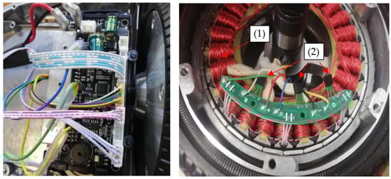
Figure 12.
(left) Original control electronics for the BLDC wheel motor. (right) The motor’s internal winding and the hall sensors for positioning.
The wheels were integrated into the robotic platform; Figure 12 (left) shows the interior of the wheel after removing the outer casing. Each wheel has an independent circuit that operates based on the movement detected by a hall effect sensor (Figure 12 (right)). By accessing the motor’s internal winding mechanism (1 in Figure 12 (right)), it was observed that the wheel had 3 hall effect sensors (2 in Figure 12 (right)), which indicate the exact position of the wheel at any given moment, facilitating precise control of the wheel.
After identifying the necessary control and power electronics for the proper functioning of the wheels, a commercial brushless DC (BLDC) motor controller was used. This included hall sensor monitoring and allowed for the turning on and off of the motors, as well as the regulation of their power (affecting both the rotational speed and torque) and the direction of rotation. Additionally, in accordance with the power of the wheels, heat sinks with high heat dissipation capacity were used to prevent overheating of the transistors that make up the controller. The motors and controller connection schematic are shown in Figure 13.
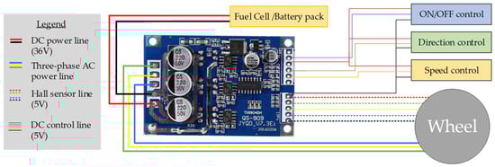
Figure 13.
Electrical connection of the motor and wheel controller.
After testing the system’s operation when connected to a power supply, with the speed manually regulated using a potentiometer, current consumption values ranging from 0 A to 1.5 A at 36 V were recorded, depending on the torque exerted by the wheel.
4.2. Control of Robotic Platform Movement via the Remote Control and Software Development
For control of the robotic platform in its early testing stages, a remote-control system was chosen due to its low cost, long range, and ease of implementation. The remote control module used was the Fly Sky FS-i6 (Adafruit Industries, New York, NY, USA), complemented by a six-channel radio frequency receiver, the FS-iA6. The FS-iA6 receiver was connected to a microcontroller (Arduino Mega 2560 Pro model), allowing the user to send signals from the remote-control module to the microprocessor (Figure 14) (see Appendix A for the software code details). Through the code developed for the microcontroller, the appropriate control signals were then applied to the wheels. Additionally, the programming platform used the Arduino IDE 2.3.2 software. The code was developed for implementation on the Arduino Mega 2560 Pro microprocessor, using interrupts to increase the available RAM memory and reduce the program cycle time. The interrupts that were used and their associated pins were INT0 (pin D2), INT1 (pin D3), INT2 (pin D21), and INT3 (pin D20), programmed to activate on a rising edge, as shown in Figure 14. The remote-control module was placed on top of the platform, in order to prevent potential risks due to flooding or waterlogging of the ground.
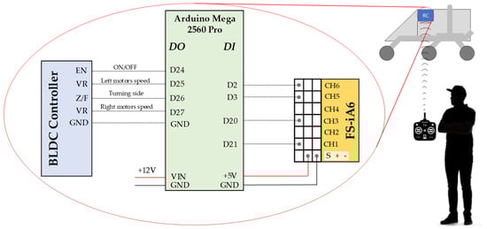
Figure 14.
Connection diagram between the FS-iA6 receiver module, Arduino Mega 2560 Pro microcontroller, and BLDC motor controller.
To convert the signal read by the microcontroller (from the remote-control receiver) into the output signal of the microcontroller (to the BLDC motor controller) in the form of PWM, the map function was used. This adjusted the PWM range of the remote-control controller’s receiver to the value that the microprocessor needed to output for the correct operation of the motors using a PWM signal, taking into account the offset errors from the remote-control module.
Finally, to achieve rotation of the robotic platform, the technique used by tracked vehicles was chosen. This involves the platform rotating around its own central axis by spinning the wheels on one side while keeping the wheels on the opposite side stationary. Then, pins D25 and D27 from the Arduino board were connected to VR pins from the BLDC controller to control the speed of the motors on the left and right sides, working independently. Pin D26 was used to decide the side over which the wheels would rotate. This provides the platform with enhanced manoeuvrability, allowing it to move over rough terrain with sharp curves and limited turning space, while eliminating the need for a servomotor to steer the driving wheels.
5. Results
To evaluate the robustness of the developed platform, different tests were conducted to check the power balance, movement, and navigation, as well as safety.
5.1. Power Balance and Autonomy Evaluation
5.1.1. Power Tests Under Different Profiles
To assess the power tests, the hydrogen–battery hybrid propulsion system was tested indoors by connecting it to a programmable electronic load with four variable demand profiles, representing the four driving modes linked to four working scenarios. The tests were conducted at 20 °C, 60% RH, and 1 atm.
Profile 1, in Figure 15a, represents a continuous duty scenario with little variation in motor speed/torque. Profile 2, in Figure 15b, represents a drastic working scenario with severe changes in wheel speed/torque on a very frequent basis. Profile 3, in Figure 15c, represents a typical outdoor in-field working scenario with power peak demand. Profile 4, in Figure 15d, represents a stationary demand profile.
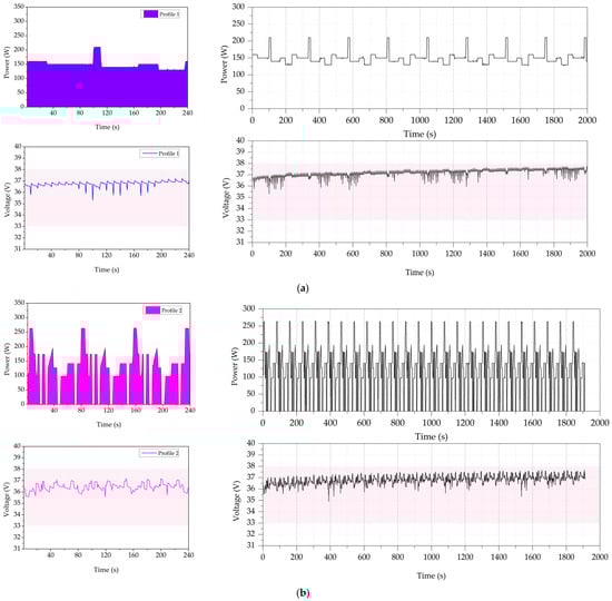
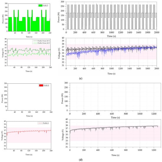
Figure 15.
Power test for the load profiles. (a) Profile 1. (b) Profile 2. (c) Profile 3. (d) Profile 4. (left): Hygrobot power profile and DC bus voltage in single intervals of 0–240 s. (right): Hygrobot power profile and DC bus voltage, built from multiple repetitions of a single interval.
As shown in Figure 15, the passive control-based power balance is capable of operating under the four profiles without exceeding the established safety limits. For Profile 1, Figure 15a shows that with a smooth power profile, the bus voltage remains stable, except for some voltage peaks caused by the internal operation of the PEM fuel cell. For Profile 2, Figure 15b shows that even with an extreme profile, the power system is still able to maintain the DC bus voltage value at ±1.5 V around 36 VDC, which is within the set limits. With respect to Profile 3, Figure 15c, the platform has been tested with two different initial voltages (34.5 V and 36 V). It can be observed that the DC bus remains within the safe values; it even tends to stabilize at 37 V, verifying the effect of the passive control. Finally, for Profile 4, Figure 15d shows that when the demand is zero, the DC bus voltage increases because the PEM fuel cell is charging the battery subsystem until it reaches 38 V. Then, the power balance system activates the overload protocol, disconnecting the PEM fuel cell from the DC bus.
For more details, Figure 16 shows the power-sharing between the PEM fuel cell and the battery subsystems for Profile 3. The PEM fuel cell subsystem is intended to operate continuously, supplying energy to the battery subsystem and meeting Hygrobot energy demand. The authors define the sign power as positive (p > 0) when power is injected into the DC bus and as negative (p < 0) when power is drawn from the DC bus.
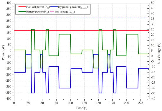
Figure 16.
Hygrobot power balance detail for Profile 3.
Based on the passive power balance (with the PEM fuel cell and battery subsystem directly connected to the DC bus, as in Figure 6), the power delivered by the PEM fuel cell remains at = 170 W. This corresponds with the available PEM fuel cell power at nominal DC bus voltage, = 36 V, as in Figure 6 and Figure 8.
When the battery subsystem is discharging, the DC bus voltage drops, increasing the power provided by the PEM fuel cell and recharging the battery subsystem. Conversely, when the battery subsystem voltage is above 36 V, the DC bus voltage rises and the power supplied by the PEM fuel cell decreases, provoking battery subsystem discharge.
The difference between Hygrobot demand and PEM fuel cell generation is supplied by the battery subsystem, which is available for charging and discharging according to the net power balance between the PEM fuel cell supply and Hygrobot demand.
5.1.2. Autonomy Evaluation
To assess the platform’s autonomy, the authors carried out tests to determine hydrogen consumption and battery subsystem SoC. Figure 17 shows the hydrogen flow consumed by the PEM fuel cell under Profile 3. It remains stable at around 3.95 dm3/min (constant electrical power delivery, with stable hydrogen consumption), with the recorded values ranging from 3.78 dm3/min to 4.36 dm3/min (measured by FT-01). Additionally, periodic peaks were recorded, which were associated with the hydrogen purge needed to guarantee the best PEM fuel cell performance. The purge happens every 10 s, and the valve is left open for 0.07 s. Based on the data reported in the test, the average hydrogen required by the Hygrobot platform is 4.05 dm3/min.
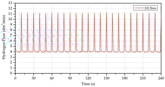
Figure 17.
Hydrogen consumption by the PEM fuel cell during the autonomy test.
Taking into account the storage capacity of the hydrogen tank, shown in Table 4, the experimental continuous operating time range of the PEM fuel cell for the demand profile, as shown in Figure 16, is calculated in Equation (13):
where:
is the experimental continuous operating time of the PEM fuel cell (min).
is the hydrogen bottle storage capacity (2000 dm3).
is the average hydrogen consumption flow (4.05 dm3/min).
This results in = 8.23 h. Therefore, the autonomy obtained from experimental tests with a variant demand profile is close to the theoretical autonomy calculated in Equation (3). The difference is due to the impact of the purge and variations in efficiency with respect to the maximum power operating point.
Finally, to evaluate the battery subsystem SoC, a long-duration test was performed with Profile 3 and Figure 15c, a duration of 3600 s (1 h) at 20 °C, and 60% RH. Figure 18 shows the evolution of the hydrogen tank and the battery subsystem SoC, as well as the DC bus voltage.
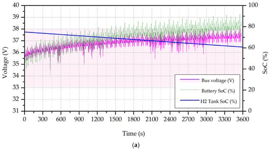
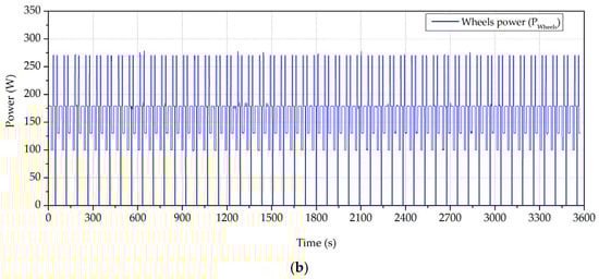
Figure 18.
(a) Hydrogen tank and battery subsystem SoC under Profile 3. (b) Hygrobot power profile.
From Figure 18, it can be concluded that the hydrogen tank reduced by 15%, while the battery subsystem SoC increased by up to 80%. In addition, the DC bus voltage increased from 35.5 V to 37 V.
5.2. Movement and Navigation Tests
5.2.1. Speed Tests
For speed tests, the authors focused on measuring the maximum linear ground speed, acceleration, and deceleration. For this purpose, tests were carried out on the four different surfaces shown in Figure 1 and Table 2, with a slope of 0° and different payloads. The results are reported in Table 6.
Table 6.
Maximum ground speed, acceleration, and braking tests, performed for different payloads and surfaces.
5.2.2. Traction Test
The torque exerted by each wheel was not provided by the manufacturer, so a traction test was carried out, as shown in Figure 19. In this test, a 0.4 m long bar was attached to the axle of the wheel, and a mass of 586.13 g was placed on the bar. The mass was then moved along the bar (from the furthest separation to the closest distance) until the wheel was able to lift the bar to the horizontal position.
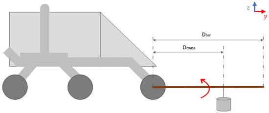
Figure 19.
Traction test for the measurement of motor torque for each wheel.
The applied lever arm was 0.4 m, while the weight lifted at its end was 0.58 kg. Additionally, the bar had a mass of 0.08 kg, which was distributed almost uniformly along its length. The maximum torque, , developed by each wheel is calculated with Equation (14):
where:
is the maximum torque developed by each wheel (Nm).
is the weight force applied by mass, with kg and = .
is the applied lever arm (0.2 m).
is the weight force applied by the bar (bar mass = 0.08 kg).
is the bar length (0.4 m).
This results in = 2.35 Nm.
Then, the total maximum torque that the Hygrobot platform can support is determined with Equation (15):
where:
is the maximum torque developed by the Hygrobot platform (Nm).
This results in = 14.80 Nm.
In addition, outdoor traction tests were carried out, with the aim of evaluating the maximum slope and weight that the platform can overcome on different terrains, as well as the maximum braking gradient that Hygrobot achieves. The obtained results are shown in Table 7.
Table 7.
Traction tests for two different terrains.
5.3. Safety Tests
The safety tests aim to check: (1) the response of the battery subsystem when it is overcharged or over-discharged, (2) the response of the hydrogen supply subsystem when hydrogen starvation occurs, and (3) to evaluate the platform behaviour under different operation conditions (temperature, humidity, and C-rate).
5.3.1. Battery Subsystem Safety Test
To verify the safety of the Hygrobot platform, an overcharged battery test was conducted, as shown in Figure 20. When ≥ 38 V, it was observed that the rheostatic braking system activated satisfactorily, engaging the power resistors and dissipating the energy excess as heat until the DC bus voltage descended to 37 V. In parallel, the control subsystem ordered the system to stop the hydrogen supply (see Figure 6); valve SOV-01 closed, valve SOV-02 opened, and Relay RLY-01 opened, causing the PEM fuel cell to be electrically disconnected from the DC bus. Conversely, if the battery subsystem voltage dropped below 33 V, the control subsystem turned off the wheel’s motors to prevent further battery discharge.
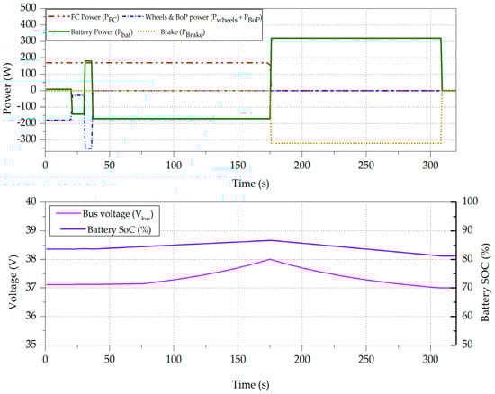
Figure 20.
Safety test: battery overcharging test.
The overcharge scenario is produced by stopping the wheels (t = 35 s) so that the battery subsystem achieves a high state of charge (SoC = 84%). The PEM fuel cell continues supplying power until the DC bus voltage rises above 38 V (t = 176 s). Then, the safety system protocol is initiated, putting the rheostatic brake on in conduction ( = −320 W) and isolating the PEM fuel cell ( = 0 W). This state of affairs lasts until the bus voltage reaches the programmed secure voltage (37 V) on the control subsystem (t = 312 s). At this point, the rheostatic brake is deactivated and the battery subsystem stops discharging, waiting for a new restart of the platform.
5.3.2. Hydrogen Supply Failure Test
The Hygrobot platform was also subjected to the hydrogen supply failure test, as shown in Figure 21. In the test, the hydrogen supply is cut off while the consumption of the wheel motors remains active, maintaining the energy demand as in Profile 3, Figure 15c. The control subsystem orders the device to electrically isolate the PEM fuel cell from the DC bus to prevent damage. The Hygrobot platform continues operating, powered by the battery subsystem but without the PEM fuel cell, until the DC bus voltage drops to ≤ 33 V, at which point, the control subsystem turns off the wheel motors to prevent further battery discharge.
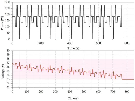
Figure 21.
Safety test: hydrogen supply failure test, showing (upper) Hygrobot power consumption and (lower) DC bus voltage.
5.3.3. Operating Condition Tests
With the aim of demonstrating the reliability of the developed platform, Hygrobot was also tested under a wide range of temperature, humidity, and charging/discharging rates to validate the correct operation of the hydrogen–battery power system. Table 8 and Figure 21 show the operating condition tests (temperature and humidity) and polarization curves obtained from the PEM fuel cell and battery subsystem.
Table 8.
Hygrobot operating condition tests for the PEM fuel cell and LiPo battery subsystem.
From the results shown in Figure 22, it can be seen that the temperature within the range studied increases the performance of the PEM fuel cell and battery subsystem without compromising their integrity, allowing the power/energy ratio between the PEM fuel cell and battery subsystem to remain constant. Conversely, an increase in ambient humidity also improves the performance of the PEM fuel cell, although this is not a necessary condition for operation due to the internal design of the PEM fuel cell, which makes it self-humidifying. Finally, it can be observed that the energy capable of being stored by the battery subsystem is higher at lower discharge coefficients, although the subsystem shows correct performance in the whole range of discharge rates studied.
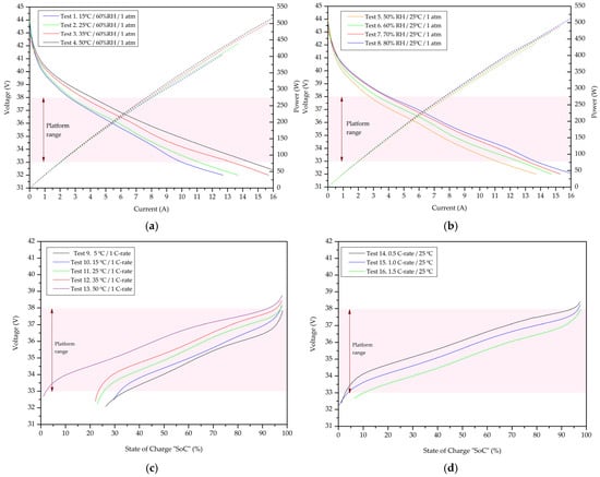
Figure 22.
Hygrobot operating condition tests for the PEM fuel cell and LiPo battery subsystem: (a) PEM fuel cell temperature tests. (b) PEM fuel cell humidity tests. (c) Battery subsystem temperature tests. (d) Battery subsystem charging/discharging rate tests.
6. Discussion
A ground robotic platform has been designed and manufactured, which is equipped with an electrical supply system that combines the use of hydrogen and battery power. Additionally, a control system has been designed to connect both technologies to a DC bus that powers the robotic platform, and safety systems have been implemented to ensure the correct operation of the electrical supply system.
Multiple tests were conducted, providing information on the platform’s performance and yielding data that allowed its comparison with commercial robotic platforms. The proposed, fully assembled platform and its main characteristics are shown in Figure 23 and Table 9.
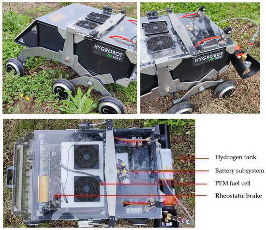
Figure 23.
Hygrobot: hydrogen–battery hybrid ground robotic platform, as developed by the authors.
Table 9.
Hygrobot technical data.
In addition, Table 10 allows a comparison of the Hygrobot platform developed by the authors with commercial ground robotic platforms found in the same sector.
Table 10.
Comparison between the commercial models of ground robotic platforms and Hygrobot.
When comparing the characteristics of Hygrobot with commercial models, it can be observed that the autonomy provided by hybridizing hydrogen and battery power offers noticeable advantages, allowing autonomous activity similar to a full working day (8 h). Additionally, the ability for a quick recharge provides the platform with an option for near-continuous operation, without the need for long waiting times between charges.
Regarding the weight of the platform (65 kg), this is still lower than the other platforms studied, making possible the installation of the sensors and actuators needed for its deployment in the working environment or to increase the platform’s autonomy by adding an extra tank.
The platform’s maximum speed (17 km/h) beats that of the commercial models, and the rate for required power/load capacity is the smallest one (6.48 W/kg). However, the wheel torque is lower, and the tyres’ size and diameter prevent the platform from carrying heavy loads on surfaces with very high friction coefficients (such as on mud or sand).
Since the working environment for which the robotic platform is designed can be harsh—due to dust, water, plants, etc.—it is noted that commercial models usually offer a high level of protection (IP67 or higher is recommended). In this case, due to the level of development of the platform (TRL 6), an IP50 insulation level was considered sufficient; however, in future works by the authors, in order to be able to commercialize the platform, they will provide the device with a casing that insulates the core components from the external environment. This will guarantee an IP67 protection degree throughout the structure, with particular attention paid to the entry point of the PEM fuel cell oxygenation system. The accumulation of particulate matter inside this can rapidly degrade the PEM fuel cell. Therefore, it is recommended that a PM10 filter or higher filter should be installed at this entry point.
Regarding the navigation system, extra equipment like RTK control systems, LiDAR, or similar technologies, combined with the option of a basic remote-control system for short-distance operation can be included in the future.
Finally, it is observed that the size of the platform is smaller than other models analysed, which could enhance its performance in adverse environments where the space is reduced or where the terrain is wet and has low cohesion.
7. Conclusions
Hygrobot offers an innovative alternative for the electrification of a rough terrain robotic platform, through the hydrogen-based hybridization of fuel cells and batteries. This device represents the valorisation of the equipment and progress towards a circular economy, due to the reuse of components. The mechanical design allows the platform to move in the three Cartesian axes, with independent movement of each wheel and maximum contact with the ground, achieving a linear maximum speed of 17 km/h (88% higher than the best-case scenario regarding commercial models). The developed hydrogen–battery hybrid power system provides the potential for greater continuous use of the platform, thanks to its highest period of autonomy (at least 2 h more than the best commercial model) and shortest recharging time of 5 min, (reducing the recharging time to one-quarter compared to the commercial models). Additionally, the rate between the required electrical power and the load capacity is the smallest one (6.48 W/kg), while the rest of the compared models have a rate higher than 10. Its design enables the developed platform to be adapted to actual and new robotic platforms without drastically modifying its architecture, leveraging components already validated in commercial vehicles, and offers scalability for different applications from warehouse logistics robots to rescue equipment; hydrogen usage enables modular system configurations in low-, medium-, and high-power segments.
Additionally, this research proposes future lines of work for the development of the mechanical system (by increasing wheel torque and the wheels’ grip on the terrain, and by improving the casing insulation system until it achieves an IP67 rating) and for the development of the energy management system (by applying algorithms that optimize the energy distribution between batteries and fuel cells to maximize the platform’s autonomy and by testing the platform under temperature conditions below 0 °C).
Therefore, Hygrobot positions itself as a key solution for industrial and service applications and shows promising development prospects.
Author Contributions
Conceptualization, F.S.M. and C.D.A.; methodology, F.S.M. and C.D.A.; software, C.D.A.; validation, C.D.A., F.S.M. and J.M.A.M.; formal analysis, F.S.M. and J.M.A.M.; resources, F.S.M. and J.M.A.M.; funding acquisition, F.S.M. and J.M.A.M. All authors have read and agreed to the published version of the manuscript.
Funding
This research was funded by (1) the Spanish Government Project, Ref. PID2023-148456OB-C41, by MICIU/AEI/10.13039/501100011033 and FEDER, UE, and (2) Spanish Government RED2022-134588-T by MICIU/AEI/10.13039/501100011033.
Institutional Review Board Statement
Not applicable.
Informed Consent Statement
Not applicable.
Data Availability Statement
To consult the experimental data, please contact the corresponding author.
Acknowledgments
The authors would like to acknowledge the research centre of CITES at the University of Huelva for putting the facility at their disposal for developing the research.
Conflicts of Interest
The authors declare no conflicts of interest.
Abbreviations
| Acronyms | |
| AWD | All-wheel drive |
| BLDC | Brushless DC |
| BMS | Battery management system |
| BoP | Balance of plant |
| FWD | Front two-wheel drive |
| PEM | Proton exchange membrane |
| PM | Particulate matter |
| RWD | Rear two-wheel drive |
| SoC | State of charge |
| Nomenclature | |
| battery subsystem capacity (Ah) | |
| battery subsystem discharge rate | |
| bar length (m) | |
| lever arm length (m) | |
| energy stored in the battery subsystem (J) | |
| electrical energy delivered by the fuel cell (J) | |
| energy stored in the form of hydrogen (J) | |
| bar force (N) | |
| weight force applied by mass (N) | |
| hydrogen lower heating value (120 MJ/kg) | |
| number of wheels | |
| gravitational attraction force due to the mass of the platform (637 N) | |
| battery subsystem power (W) | |
| maximum power provided by the battery subsystem (W) | |
| power consumed by the BoP of the PEM fuel cell (W) | |
| average power dissipated by brakes (W) | |
| fuel cell power (W) | |
| maximum power provided by the hydrogen–battery hybrid system (W) | |
| power consumed by the robotic platform (W) | |
| maximum power consumed by the robotic platform (W) | |
| power consumed by the wheel (W) | |
| maximum power consumed by the wheel (W) | |
| wheels resistance force (N) | |
| rolling resistance coefficient | |
| battery continuous operating time (h) | |
| PEM fuel cell continuous operating time (h) | |
| experimental continuous operating time range of the PEM fuel cell (min) | |
| maximum torque developed by the Hygrobot platform (Nm) | |
| torque developed wheel (Nm) | |
| hydrogen volume stored in the bottle (dm3) | |
| battery subsystem voltage (V) | |
| hydrogen bottle storage capacity (dm3) | |
| average hydrogen consumption flow (dm3/min) | |
| slope angle of the surface | |
| hydrogen density at 20 °C and 1 atm (0.089 g/dm3) | |
| PEM fuel cell efficiency (%) |
Appendix A. C++ Hygrobot Movement Code
//        Pins and library declaration
//------------------------------------------------------------------------------
// Digital pins Arduino mega 2560
#define pin_INT_Avance 20   // Advance control (Channel 3)
#define pin_INT_Giro 21     // Left-right turn control (Channel 1)
#define pin_INT_Reversa 3  // Switch de avance/retroceso (Canal 5)
#define pin_INT_ON_OFF 2  // Switch ON/OFF (Channel 6)
//Wheels motor pins declaration
#define pin_OUT_Avance_Der 13 //Right wheels speed control
#define pin_OUT_Reversa_Der 12 //Right wheel advance control
#define pin_OUT_Reversa_Izq 9 //Left wheel advance control
#define pin_OUT_Avance_Izq 11 // Left wheels speed control
#define pin_OUT_ON_OFF 10 //Pin ON/OFF
//Libraries
#include <EnableInterrupt.h> //Interrupts library
//------------------------------------------------------------------------------
//           Variable declaartion
//------------------------------------------------------------------------------
//Constants declarations
float RC_Avance_consigna, RC_Reversa_consigna, RC_Reversa_consigna_inversa, RC_ON_OFF_consigna; //RC variables
double RC_Giro_consigna, RC_Avance_Derecha, RC_Avance_Izquierda;   //RC variables
//Constant RC
// Advance
const int RC_max_Avance_raw = 2010;
const int RC_min_Avance_raw = 1000;
const float Ardu_max_Avance = 255;
const float Ardu_min_Avance = 0;
// Turn
const float RC_max_Giro_raw = 2010;
const float RC_min_Giro_raw = 965;
const float Ardu_max_Giro = 10;
const float Ardu_min_Giro = -10;
// SWITCH REVERSE
const float RC_max_Reversa_raw = 2010;
const float RC_min_Reversa_raw = 940;
const int Ardu_max_Reversa = 255;
const int Ardu_min_Reversa = 0;
// SWITCH ON/OFF
const float RC_max_ON_OFF_raw = 2000;
const float RC_min_ON_OFF_raw = 960;
const int Ardu_max_ON_OFF = 255;
const int Ardu_min_ON_OFF = 0;
//------------------------------------------------------------------------------
//        Interrupts declarations
//------------------------------------------------------------------------------
// RC advance
volatile long Avance_HIGH_us;
volatile int RC_Avance_raw;
void INT_Avance() {
  if (digitalRead(pin_INT_Avance) == HIGH) Avance_HIGH_us = micros();
  if (digitalRead(pin_INT_Avance) == LOW)  RC_Avance_raw  = micros() - Avance_HIGH_us;}
// RC turn
volatile long Giro_HIGH_us;
volatile int RC_Giro_raw;
void INT_Giro() {
  if (digitalRead(pin_INT_Giro) == HIGH) Giro_HIGH_us = micros();
  if (digitalRead(pin_INT_Giro) == LOW)  RC_Giro_raw  = micros() - Giro_HIGH_us;}
// SWITCH REVERSE
volatile long Reversa_HIGH_us;
volatile int RC_Reversa_raw;
void INT_Reversa() {
  if (digitalRead(pin_INT_Reversa) == HIGH) Reversa_HIGH_us = micros();
  if (digitalRead(pin_INT_Reversa) == LOW)  RC_Reversa_raw  = micros() - Reversa_HIGH_us;}
// SWITCH ON/OFF
volatile long ON_OFF_HIGH_us;
volatile int RC_ON_OFF_raw;
void INT_ON_OFF() {
  if (digitalRead(pin_INT_ON_OFF) == HIGH) ON_OFF_HIGH_us = micros();
  if (digitalRead(pin_INT_ON_OFF) == LOW)  RC_ON_OFF_raw  = micros() - ON_OFF_HIGH_us;}
//-----------------------------------------------------------------------------
//      Programme main funtion
//-----------------------------------------------------------------------------
void setup() {
  // RC interruptions
 // pinMode(pin_INT_Avance, INPUT_PULLUP);              // Advance speed
  enableInterrupt(pin_INT_Avance, INT_Avance, CHANGE);
  pinMode(pin_INT_Giro, INPUT_PULLUP);                  // Turn right-left
  enableInterrupt(pin_INT_Giro, INT_Giro, CHANGE);
  pinMode(pin_INT_Reversa, INPUT_PULLUP);                  // Switch reverse
  enableInterrupt(pin_INT_Reversa, INT_Reversa, CHANGE);
  pinMode(pin_INT_ON_OFF, INPUT_PULLUP);                  // Switch on/off
  enableInterrupt(pin_INT_ON_OFF, INT_ON_OFF, CHANGE);
  //Output controllers
  pinMode(pin_OUT_Avance_Izq, OUTPUT);
  pinMode(pin_OUT_Avance_Der, OUTPUT);
  pinMode(pin_OUT_Reversa_Izq, OUTPUT);
  pinMode(pin_OUT_Reversa_Der, OUTPUT);
  pinMode(pin_OUT_ON_OFF, OUTPUT);
  //Rehostatic break
  pinMode(pin_Freno, OUTPUT);
// Serial port spped
Serial.begin(115200);}
void loop() {
//RC-Arduino mapping
RC_Avance_consigna = map(RC_Avance_raw, RC_min_Avance_raw, RC_max_Avance_raw, Ardu_min_Avance,    Ardu_max_Avance);
  RC_Giro_consigna   = map(RC_Giro_raw, RC_min_Giro_raw, RC_max_Giro_raw, Ardu_min_Giro, Ardu_max_Giro);
RC_Reversa_consigna   = map(RC_Reversa_raw, RC_min_Reversa_raw, RC_max_Reversa_raw, Ardu_min_Reversa, Ardu_max_Reversa);
RC_ON_OFF_consigna = map(RC_ON_OFF_raw, RC_min_ON_OFF_raw, RC_max_ON_OFF_raw, Ardu_min_ON_OFF,   Ardu_max_ON_OFF);
 //advance logic
  if (RC_Reversa_consigna <50){
  RC_Reversa_consigna_inversa = 240;}
  else{RC_Reversa_consigna_inversa = 30;}
  //Turn logoc
  if(RC_Giro_consigna > 2.0){
    RC_Avance_Izquierda = RC_Avance_consigna;
    RC_Avance_Derecha = RC_Avance_consigna*(1.0-(RC_Giro_consigna/10.0));}
  else if(RC_Giro_consigna < -2.0){
    RC_Avance_Izquierda = RC_Avance_consigna*(1.0+(RC_Giro_consigna/10.0));
    RC_Avance_Derecha = RC_Avance_consigna;}
  else{
    RC_Avance_Izquierda = RC_Avance_consigna;
    RC_Avance_Derecha = RC_Avance_consigna;}

 analogWrite(pin_OUT_Reversa_Der, RC_Reversa_consigna);
  analogWrite(pin_OUT_Reversa_Izq, RC_Reversa_consigna_inversa);
  analogWrite(pin_OUT_ON_OFF, RC_ON_OFF_consigna);
  analogWrite(pin_OUT_Avance_Izq, RC_Avance_Izquierda);
  analogWrite(pin_OUT_Avance_Der, RC_Avance_Derecha);
}
References
- Raj, R.; Kos, A. A Comprehensive Study of Mobile Robot: History, Developments, Applications, and Future Research Perspectives. Appl. Sci. 2022, 12, 6951. [Google Scholar] [CrossRef]
- Ullah, I.; Adhikari, D.; Khan, H.; Anwar, M.S.; Ahmad, S.; Bai, X. Mobile robot localization: Current challenges and future prospective. Comput. Sci. Rev. 2024, 53, 100651. [Google Scholar] [CrossRef]
- Llerena, F.I.; González, E.L.; Mancera, J.J.C.; Manzano, F.S.; Andújar, J.M. Hydrogen vs. Battery-Based Propulsion Systems in Unipersonal Vehicles—Developing Solutions to Improve the Sustainability of Urban Mobility. Sustainability 2021, 13, 5721. [Google Scholar] [CrossRef]
- Mikołajczyk, T.; Mikołajewski, D.; Kłodowski, A.; Łukaszewicz, A.; Mikołajewska, E.; Paczkowski, T.; Macko, M.; Skornia, M. Energy Sources of Mobile Robot Power Systems: A Systematic Review and Comparison of Efficiency. Appl. Sci. 2023, 13, 7547. [Google Scholar] [CrossRef]
- Llerena, F.I.; Barranco, Á.F.; Bogeat, J.A.; Segura, F.; Andújar, J.M. Converting a Fixed-Wing Internal Combustion Engine RPAS into an Electric Lithium-Ion Battery-Driven RPAS. Appl. Sci. 2020, 10, 1573. [Google Scholar] [CrossRef]
- Wu, Y.; Huang, Z.; Li, D.; Li, H.; Peng, J.; Stroe, D.; Song, Z. Optimal battery thermal management for electric vehicles with battery degradation minimization. Appl. Energy 2023, 353, 122090. [Google Scholar] [CrossRef]
- Dudek, M.; Zarzycki, M.; Raźniak, A.; Rosół, M. Applying a 2 kW Polymer Membrane Fuel-Cell Stack to Building Hybrid Power Sources for Unmanned Ground Vehicles. Energies 2023, 16, 7531. [Google Scholar] [CrossRef]
- Zarzycki, M.; Dudek, M.; Raźniak, A.; Masłowski, A.; Perski, A.; Czupryniak, R. Development of criteria for the selection and investigation of PEMFC stacks as components of hybrid energy sources for UGVs. In Proceedings of the 2024 28th International Conference on Methods and Models in Automation and Robotics (MMAR), Miedzyzdroje, Poland, 27–30 August 2024; pp. 568–573. [Google Scholar]
- Keiyinci, S.; Aydin, K. Ground simulation of fuel cell/battery hybrid propulsion system for small unmanned air vehicles. Aircr. Eng. Aerosp. Technol. 2021, 93, 783–793. [Google Scholar]
- Verstraten, T.; Hosen, M.S.; Berecibar, M.; Vanderborght, B. Selecting suitable battery technologies for untethered robot. Energies 2023, 16, 4904. [Google Scholar] [CrossRef]
- Ibericadrone, Ibericadron XAG R150 V2. Available online: https://www.ibericadron.com/tienda/agricultura/robot-agricola-terrestre/ (accessed on 21 November 2024).
- Tecmundo, Milidón M50. Available online: https://www.tecmundo.com/robot-para-la-agricultura-m50 (accessed on 17 November 2024).
- Robotnik, RB-VOGUI. Available online: https://robotnik.eu/es/productos/robots-moviles/rb-vogui/ (accessed on 22 November 2024).
- Hua, Z.; Zheng, Z.; Pahon, E.; Péra, M.C.; Gao, F. A review on lifetime prediction of proton exchange membrane fuel cells system. J. Power Sources 2022, 529, 231256. [Google Scholar] [CrossRef]
- Ydrefors, L.; Hjort, M.; Kharrazi, S.; Jerrelind, J.; Trigell, A.S. Rolling resistance and its relation to operating conditions: A literature review. Proc. Inst. Mech. Eng. Part D J. Automob. Eng. 2021, 235, 2931–2948. [Google Scholar]
- Steyn, W.; Warnich, J. Comparison of tyre rolling resistance for different mountain bike tyre diameters and surface conditions. S. Afr. J. Res. Sport Phys. Educ. Recreat. 2014, 36, 179–193. [Google Scholar]
- Liu, W.; Tupe, J.A.; Aguey-Zinsou, K.F. Metal Hydride Storage Systems: Approaches to Improve Their Performances. Part. Part. Syst. Charact. 2024, 42, 2400163. [Google Scholar] [CrossRef]
- ISO 16111:2018; Transportable Gas Storage Devices—Hydrogen Absorbed in Reversible Metal Hydride. International Organization for Standardization: Geneva, Switzerland, 2018.
- UN 3479; Hydrogen in Metal Hydride Storage Systems. Recommendations on the Transport of Dangerous Goods: Model Regulations (21st revised ed.). United Nations Economic Commission for Europe (UNECE): Geneva, Switzerland, 2019.
- Franco, A.; Giovannini, C. Hydrogen Gas Compression for Efficient Storage: Balancing Energy and Increasing Density. Hydrogen 2024, 5, 17. [Google Scholar] [CrossRef]
- Habib, M.A.; Abdulrahman, G.A.Q.; Alquaity, A.B.S.; Qasem, N.A.A. Hydrogen combustion, production, and applications: A review. Alex. Eng. J. 2024, 100, 182–207. [Google Scholar] [CrossRef]
- La Camera, F. International Renewable Energy Agency, Making the Breakthrough: Green Hydrogen Policies and Technology Costs; IRENA: Abu Dhabi, United Arab Emirates, 2021. [Google Scholar]
Disclaimer/Publisher’s Note: The statements, opinions and data contained in all publications are solely those of the individual author(s) and contributor(s) and not of MDPI and/or the editor(s). MDPI and/or the editor(s) disclaim responsibility for any injury to people or property resulting from any ideas, methods, instructions or products referred to in the content. |
© 2025 by the authors. Licensee MDPI, Basel, Switzerland. This article is an open access article distributed under the terms and conditions of the Creative Commons Attribution (CC BY) license (https://creativecommons.org/licenses/by/4.0/).