1. Introduction
In the past, bored cast-in-place piles, precast-driven piles, and steel-reinforced composite piles were widely used in pile foundation projects both domestically and internationally. However, bored cast-in-place piles often caused mud pollution, and problems such as mud skin on the pile side, soft soil collapse, and pile bottom sediment were also common. Precast-driven piles faced difficulties in driving into hard layers, significant soil displacement effects, high noise levels during pile driving, and insufficiently secure pile joint connections. Steel-reinforced composite piles required high construction precision, and the post-inserted piles had low shear strength and were prone to tilting, overstepping, and poor concentricity. Their construction time was limited, insertion was difficult, the pile driver was too tall, and the cost was relatively high. In addition, most existing piles were of equal diameter, [
1,
2,
3,
4,
5,
6,
7] resulting in waste of pile body strength in the deep part and poor economy. Xi Chenxin [
8] systematically analyzed the vertical bearing characteristics of large-diameter steel tube concrete composite piles in the pile foundation of a highway bridge over a river. The results showed that due to the superior engineering properties of steel casing materials compared to reinforced concrete materials, the mechanical properties of steel tube concrete composite piles were superior to those of reinforced concrete piles. Under the same working conditions, the safety reserve of the bearing capacity of steel tube concrete composite piles was much higher than that of reinforced concrete piles, which was obviously not conducive to economic and social benefits. At that time, steel tube concrete piles [
9,
10,
11,
12,
13] generally adopted the mode of driving in the steel tube first and then pouring the pile core concrete. It was difficult to ensure the verticality of the steel tube. The steel tube was usually an open pile, and after driving, there was a lot of soil in the pile. It was difficult to remove the soil in the steel tube. After cleaning, there was still a lot of residual soil and groundwater in the hole, and the quality of concrete pouring in the steel tube was not easy to ensure. The construction was difficult, the process of removing soil in the steel tube was complex, and the construction cost was high.
Aiming at the problem of soft soil subgrade reinforcement treatment near operating lines and the defects of traditional composite piles and bored cast-in-place piles, Hohai University independently developed a new type of steel tube concrete mixing composite pile (Patent No.: ZL.2017 1 1294958.6). This new pile type could be completed with a single-machine tool. The conventional mixing pile machine was improved in terms of power to achieve the synchronous sinking of steel pipes and rotary jet grouting mixing operations to form piles. The steel tubes were connected by a threaded joint rotation, which was fast and had high connection strength. After pouring concrete into the steel tube, the shear strength at the joint was consistent with that of the pile body, and there was no weak connection point between sections. The steel tube was connected by a rod method for rotary spraying, mixing, and pouring in one operation, avoiding the problems of high working space requirements, easy eccentricity, and weak shear capacity in conventional core-inserting pile operations. The construction machine could be adjusted in height, ranging from 4 m to 40 m, and the length of each section of the steel tube could be adjusted according to the site environment. The machine could also use new mixing blades to crush and cut underground geotechnical materials such as drainage boards, adapting to various site environments. Before pouring concrete, the center of the composite pile was an empty steel tube, and a measuring rope could be placed in the empty steel tube to measure the pile length one by one. The detection method was simple and reliable. This new pile type used a large-diameter steel tube as the core pile and the transmission structure of the rotary spraying and mixing pile. The large diameter of the steel tube provided strong torsional resistance and good penetration ability. The steel tube could be coated with a rust-proof coating, and it was well protected from corrosion by the internal concrete and external cement soil. This pile type was composed of the outer layer of large-diameter cement soil pile providing the side frictional resistance and the steel tube concrete rigid core pile bearing the high-intensity load. It significantly reduced the amount of core pile concrete required to obtain the same side frictional resistance, fully leveraging the material performance advantages of both flexible and rigid piles. Since steel tubes were general commodities with various models and sizes, and different sizes of steel tubes could be easily connected with variable diameter joints, the steel tube core pile could be designed in sections according to the distribution of axial force along the pile body at different depths. This allowed the pile body to match the axial force it experienced, resulting in a more rational force distribution and enabled segmented design. This new pile type did not produce mud, waste residue, or other waste materials. Compared with driven pile types, it generated less construction noise. During the construction process, the pile head mixed the soil below and around the steel tube with cement slurry to form a fluid cement soil before the steel tube sank together with the pile head. This resulted in minimal soil displacement effect on the surrounding soil layers and no risk of hole collapse.
Since the main load-bearing capacity of this pile type was undertaken by the rigid core pile, the core objective of this study was to investigate the vertical load-bearing characteristics of steel–concrete composite mixing piles with a core, and to clarify their load-bearing mechanisms and performance. Through single-pile vertical compression static load field tests, the deformation and load-bearing conditions of the pile body under different loading conditions were directly observed and recorded. Numerical simulation analysis was conducted using the PLAXIS 3D (20.1.0.98) finite element software to predict the stress distribution and load-bearing capacity changes in the pile body under different mixing pile diameters, steel pipe diameters, and steel pipe thicknesses.
2. Site Geological Conditions and Test Pile Overview
2.1. Project Background
The field tests were conducted as part of the reconstruction project of the Beijing–Shanghai Railway from Lvcheng to Benniu section in Xincheng District, Changzhou. Due to the expansion of the Xinmeng River channel, the riverbank spacing needed to be widened to 136 m, and the riverbed was to be excavated by approximately 3 m. The existing railway bridge needed to be relocated and rebuilt on its south side. The foundation was characterized by thick layers of soft soil (with a maximum depth of 25 m) that required treatment. Given that the project was adjacent to the operational Beijing–Shanghai Railway, it was essential to minimize disturbances to the existing soft soil foundation during construction and avoid the impact of embankment fill loads on the operational line. Therefore, a low-height, low-disturbance, and effective pile foundation was required. To this end, Hohai University independently developed a steel tube concrete mixing composite pile.
2.2. Site Geological Conditions
The test site was located in Xincheng District, Changzhou. The physical and mechanical properties of each soil layer are shown in
Table 1. In
Table 1,
represents the modulus of elasticity of the soil, indicating the relationship between stress and strain during the elastic deformation stage.
C denotes cohesion, a component of the soil’s shear strength, reflecting the binding force between soil particles.
represents the internal friction angle, another important indicator of the soil’s shear strength, characterizing the frictional properties between soil particles.
2.3. Pile Test Parameters
This project was a reconstruction project of the Beijing–Shanghai Railway. According to the design documents, the foundation type was a pile foundation, utilizing steel tube concrete mixing composite piles. A new type of mixing pile machine [
14] was employed to integrally form the piles by mixing steel tubes with cement soil. In accordance with the Steel Structure Design Standard [
15], the steel pipes were made of Q235 hot-rolled seamless steel with a design compressive strength of 200 MPa. This material has good mechanical and processing properties, which can meet the load-bearing requirements under complex construction conditions and long-term use. Different pile types used steel pipes of different diameters and wall thicknesses. For example, Pile No. 1 had a design load capacity (characteristic value) of 3500 kN. Based on the Steel Structure Design Standard, a commonly available steel pipe with a diameter of 273 mm and a thickness of 16 mm was selected to ensure that the steel pipe would not fail under compression, tension, or bending moments. The cement content in the cement soil mixing piles was 20%, determined in accordance with the Technical Code for Building Foundation Treatment (JGJ 79) [
16] and other relevant standards, through laboratory tests and engineering experience. This cement content ensures that the cement soil achieves the desired strength and durability, allowing it to work together with the steel pipe to form a stable composite pile. The strength grade of the pile core concrete was C30, which complies with the requirements of the Code for Design of Concrete Structures (GB 50010) [
17] regarding concrete strength and durability. This ensures that the pile has sufficient compressive strength and load-bearing capacity to function properly over its service life, as shown in
Table 2. The designed ultimate vertical compressive bearing capacity of Pile No. 1 was 7000 kN, and that of Pile No. 2 was 6000 kN. The load was applied to Pile No. 3 and Pile No. 4 until failure occurred. The relevant parameters of the test piles are shown in
Table 3.
2.4. Pile Construction for the Test Piles
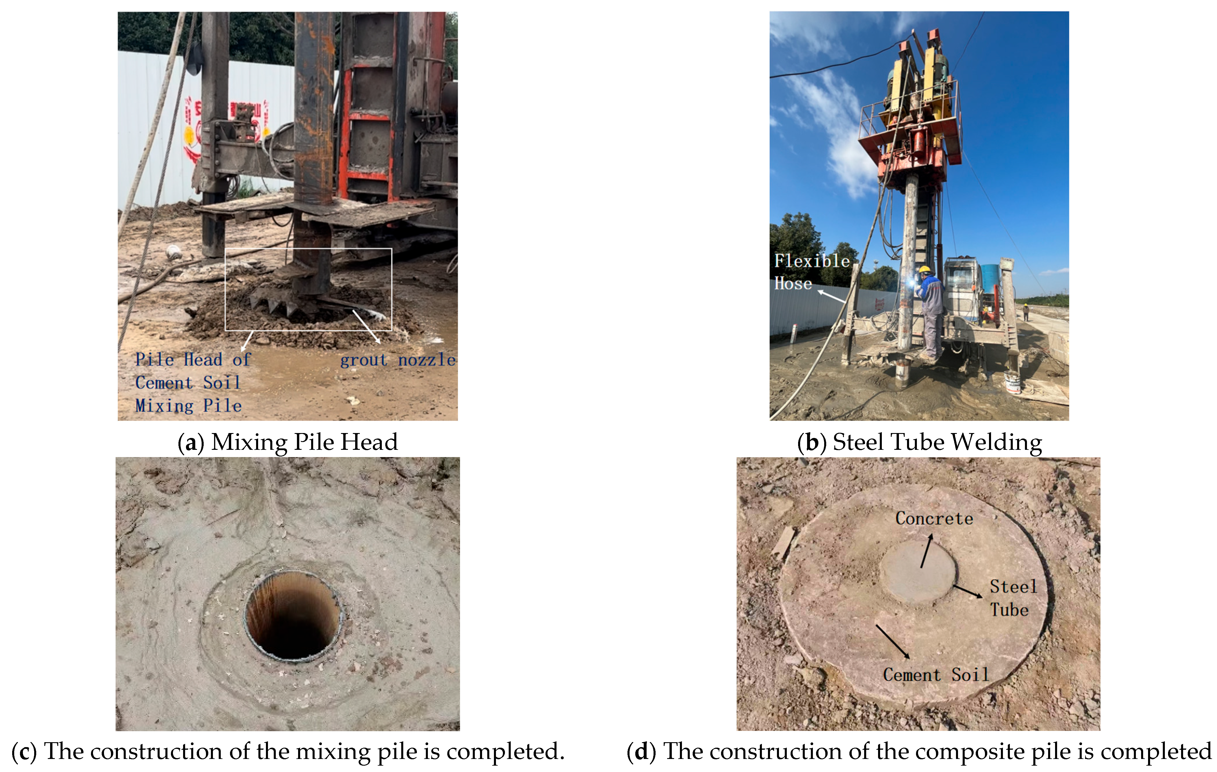
The construction process of the test pile is shown in
Figure 1.
The pile driver for the steel–concrete composite mixing pile included a frame, a lifting mechanism, a rotating mechanism, a steel pipe, a flexible conduit, a drill bit, and a grout pipe. The lifting mechanism was mounted on the frame. The rotating mechanism was connected to the lifting mechanism, which could drive the rotating mechanism to move vertically up and down. The first end of the steel pipe was connected to the rotating mechanism, which could drive the steel pipe to rotate around its axis. The second end of the steel pipe was detachably connected to the drill bit through a locking device. One end of the flexible conduit was connected to the drill bit, and the other end was connected to the pouring opening of the steel pipe. One end of the grout pipe was connected to a slurry pump through a spray head and a grout inlet pipe, and the other end was threadedly connected to the drill bit. The locking device included an L-shaped groove and a strip-shaped plate, which could be engaged or disengaged. This ultimately enabled the recovery of the steel pipe and grout pipe, improving the concentricity of the new type of cast-in-place concrete composite pile. The pile driver is shown in
Figure 2 [
14].
Construction of Steel Tube Concrete Mixing Composite Piles
1. The first section of the steel tube was welded to the pile head, and grout pipes were installed. The grout pipes were connected to the grout pump via flexible hoses.
2. The steel tube was securely clamped to the pile machine’s clamping block. The pile machine was then moved to align the pile head with the designated pile position.
3. The pile machine was started to drill the steel tube mixing pile to the predetermined depth. During the sinking of the steel tube mixing pile, the grout pump was activated to inject cement mortar into the foundation through the grout pipes.
4. While grouting, the steel tube was rotated and lifted simultaneously. The lifting speed of the mixing machine was strictly controlled according to the design specifications.
5. The steel tube mixing pile was then rotated and sunk back into the foundation to the predetermined depth. This process was repeated three to five times (multiple mixing processes ensured thorough mixing of the soft soil and additives). The next section of the steel tube was welded, and steps (2) to (5) were repeated until the construction of the steel tube mixing pile was completed. After removing the grout pipes, concrete was poured into the hollow steel tube to form the pile, completing the construction of the steel tube concrete mixing composite pile. The construction process flowchart is shown in
Figure 3.
3. Analysis of the Load-Bearing Characteristics of a Single Pile
3.1. Field Tests on the Load-Bearing Capacity of Single Piles
After a curing period of 28 days, the four test piles were subjected to single-pile vertical static load tests. For the static load tests on the load-bearing capacity of single piles, precast concrete blocks were used as the loading material, as shown in
Figure 4. The loading method employed in the tests was the slow-maintained loading method [
18].
The analysis of single pile bearing characteristics was conducted in accordance with the Technical Code for Building Pile Foundations [
19]. The load–settlement curves during the test are shown in
Figure 5. When Pile No. 1 was loaded to 8500 kN, a significant sudden drop in the pile head settlement was observed, and loading was terminated. The load then rapidly decreased to 7200 kN, with a maximum deformation of 43 mm. After unloading, the final deformation was 15 mm, corresponding to a rebound rate of 65%. When Pile No. 2 was loaded to 6600 kN, the designed ultimate bearing capacity requirement was met, and loading was stopped. The maximum pile head settlement was 38 mm, and the load–settlement curve did not exhibit a significant sudden drop. After unloading, the final deformation was 15 mm, with a rebound rate of 60%. Loading of Piles No. 3 and No. 4 was also terminated when a significant sudden drop in pile head settlement was observed. For Pile No. 3, the maximum deformation was 32 mm, and the final deformation after unloading was 20 mm, with a rebound rate of 37%. The ultimate bearing capacity of Pile No. 3 stabilized at 2100 kN, which is 40% higher than that of a traditional thin-walled concrete pipe pile of the same size [
20]. For Pile No. 4, the ultimate bearing capacity stabilized at 1400 kN, with a maximum deformation of 22 mm. After unloading, the final deformation was 15 mm, corresponding to a rebound rate of 32%.
3.2. Axial Force of Steel Tube
The steel tubes were made of Q235 hot-rolled seamless steel (Tianjin Youfa Steel Pipe Group Sales Co., Ltd., Tianjin, China). The yield strength of the steel was determined to be 235 MPa, and the elastic modulus was 2.1 × 10
5 MPa through standard tensile tests of metallic materials [
21]. Strain sensors were embedded in the inner wall of the steel tubes to monitor the variation of axial strain with depth during the load test. For Pile No. 1, strain sensors were embedded at depths of 1.0 m, 2.0 m, 5.0 m, 10.0 m, 19.5 m, 29.5 m, and 39.5 m below the pile head. For Pile No. 2, strain sensors were embedded at depths of 1.0 m, 2.0 m, 5.0 m, 10.0 m, 19.5 m, 25.0 m, 29.5 m, 35.0 m, and 39.5 m below the pile head. For Piles No. 3 and No. 4, strain sensors were embedded at depths of 1.0 m, 2.0 m, 5.0 m, 10.0 m, and 21.5 m below the pile head. The locations of the sensors are shown in
Figure 6.
Strain data were collected from strain sensors using a multi-channel static strain gauge. When calculating the longitudinal stress on the inner wall of the steel tube, the confining effect of the steel tube on the concrete was taken into account [
22]. The axial force conditions of the steel tube at different positions during the test are shown in
Figure 7.
For four different sizes of steel tube concrete mixing composite piles, the axial force of the steel tube decreased with increasing depth. As shown in
Figure 7, for Piles No. 1 and No. 3, the axial force of the steel tube decreased significantly with depth in the lower half of the pile length. In the interval from the middle to the end of the pile, the axial force was relatively small, indicating that using a constant-diameter design in this part would lead to material waste. Comparing Pile No. 1 with Pile No. 2 and Pile No. 3 with Pile No. 4, it could be concluded that a variable-diameter design could more effectively transfer the load in the interval from the middle to the end of the pile length through the cement soil surrounding the steel tube to the soil around the pile. As the load was gradually transferred downward, it was also gradually diffused through the cement soil surrounding the steel tube to the soil around the pile, forming a double-layer load diffusion mode: diffusion from steel tube concrete to cement soil and from cement soil to the soil around the pile. This double-layer load transfer system effectively transferred the upper load to a larger range of soil. Pile No. 2 used 78% of the steel of Pile No. 1 but could achieve 93% of the load-bearing capacity of Pile No. 1. In summary, a variable-diameter design was more suitable for steel tubes. When designing variable-diameter and steel tube thickness adjustment for steel tube concrete mixing composite piles, operations in the lower half of the pile length were more effective.
3.3. The Axial Force of Cement Soil and the Axial Force of Concrete
As shown in
Figure 6, soil pressure cells were installed at depths of 1 m, 2 m, and 5 m below the surface of the cement soil outside the pile to measure the internal soil pressure of the cement soil under the action of the upper load. The axial force of the cement soil was calculated using Equation (1). The axial force conditions of the cement soil at different depths during the test are shown in
Figure 8. Also, as shown in
Figure 6, rebar strain gauges were embedded in the center of the pile to monitor the variation of axial stress in the concrete with depth. The embedding depths of the rebar strain gauges were the same as those of the strain sensors. A frequency meter was used to collect the frequency data of the rebar strain gauges. The axial force conditions of the concrete at different depths during the experiment are shown in
Figure 9.
In the formula, represents the axial force of the cement soil or the axial force of the concrete; is the calibration coefficient of the soil pressure cell or the rebar strain gauge; is the measured frequency; is the initial frequency; is the cross-sectional area.
As shown in
Figure 8, the axial force of the cement soil at different depths of the test piles increased with the increment of the load. Among them, the axial force at 1 m below the cement soil mixing pile was minimal, while the axial forces at 2 m and 5 m below the pile were similar in magnitude. Therefore, the axial force at the 5 m position was selected for the analysis of the load-sharing condition of the pile body.
For Pile No. 2, the readings of the rebar strain gauge at a depth of 39.5 m from the pile head were unstable and varied significantly, rendering the collected data invalid. As shown in
Figure 9, the axial force of the concrete decreased with depth. Under the action of vertical load, the soil around the pile exerted an upward resistance to prevent the pile from sinking, and the side frictional resistance of the pile was mobilized, resulting in a continuous decrease in the axial force of the concrete along the pile body. As the upper load continued to increase and the pile body sank further, the side frictional resistance was further mobilized, and the axial force of the concrete also increased. Through the pile body as a load transfer channel, more load was transferred to the pile end, and the end-bearing capacity of the pile was also mobilized.
Based on the monitoring data of the axial force of the concrete in Pile No. 1, the axial force experienced by the concrete showed a significant peak in the section from the pile head to half the pile length. Accordingly, when designing the variable diameter and adjusting the steel tube thickness of the steel tube concrete mixing composite pile, the focus of design optimization was placed on the part below half the pile length. In this way, the load-bearing capacity of the steel tube concrete could be fully utilized in the pile structure, redundant material consumption could be reduced, and the material utilization efficiency of the composite pile could be improved.
3.4. Load-Sharing of Pile Body
In the steel tube concrete mixing composite pile, the steel tube, concrete, and cement soil collectively bore the axial load transmitted from the upper structure. According to the principle of force equilibrium, the total axial load was equal to the sum of the axial forces borne by the steel tube, concrete, and cement soil. Let the total axial load be
, the axial force borne by the steel tube be
, and the axial force borne by the concrete be
. Thus, the load-sharing ratio of the steel tube concrete was
, the load-sharing ratio of the concrete was
, and the load-sharing ratio of the cement soil mixing pile was
. (where
=
+
+
). The load-sharing ratios of the three different materials are shown in
Figure 10.
As shown in
Figure 10, when the load on Pile No. 1 was less than 2800 kN, the load shared by the steel tube and concrete increased gradually with the increase in the load, while the load shared by the cement soil decreased gradually. When the load reached 2800 kN, the load-sharing ratio of the cement soil was 18.6%. After the load reached 3500 kN, with the increase in the load, the load-sharing ratio of the steel tube continued to increase, the load-sharing ratio of the cement soil tended to be relatively stable, and the load-sharing ratio of the concrete gradually decreased. When the load reached 7000 kN, the load-sharing ratios were approximately 53% for concrete, 28% for steel tube, and 19% for cement soil. At this time, the design load capacity (characteristic value) was 7000/2 = 3500 kN. When the pile met the design requirements, the combined load shared by the steel tube and concrete was four times that shared by the cement soil. The load-sharing results of the pile body indicated that in this pile-type structural system, the steel tube concrete rigid core pile, due to its material properties, bore the high-intensity load and became the key load-bearing component of the entire pile foundation system, thus effectively supporting the various loads applied by the upper structure.
4. Finite Element Numerical Analysis
4.1. Model Establishment
The steel–concrete composite mixing pile was simulated using PLAXIS 3D. For the material constitutive models, the pile, which was composed of cement soil, steel pipe, and concrete, was considered a linear elastic material, and thus a linear elastic model was selected. Since soil settlement was taken into account, other various soil layers were modeled using the soil hardening model. The soil layer parameters are shown in
Table 1 of
Section 2. The model consisted of eight soil layers with a total depth of 47.92 m. The model had dimensions in the horizontal direction of
m,
m,
m, and
m, to minimize boundary effects. In the model, the steel tube material was defined as a plate with parameters corresponding to Q235 steel, the concrete was defined as C30, and the outer core was modeled using cement soil parameters with a cement content of 20%, as shown in
Table 2 of
Section 2. The contact surface between the steel pipe and concrete was defined as a negative interface, and the contact surface between the steel pipe and cement soil was defined as a positive interface. Additionally, the contact surface between the cement soil and the surrounding soil was established. The mesh was refined during the computation, with the pile top displacement as the key indicator. When the mesh was refined to the point where the change in pile top displacement between two consecutive calculations was less than 3%, the mesh was considered to have converged. The model used a “medium” global coarseness option, with a relative element size value of approximately 0.05. This was a balance between the overall model size and computational accuracy, ensuring sufficient computational efficiency while providing relatively accurate results in critical areas. The mesh division included a total of 225,247 solid 3D elements and 357,345 nodes. Under the “medium” coarseness setting, the element edge lengths in most areas were around 0.5 m–1 m. In locally refined areas, the element edge lengths were 0.2 m–0.3 m. Element size: In PLAXIS 3D, the soil used 10-node tetrahedral elements, with element volumes varying in different locations. In general areas, the element volume was approximately 0.10 m
3–0.20 m
3, while in refined areas, the element volume was about 0.01 m
3–0.03 m
3. The finite element model mesh is shown in
Figure 11.
4.2. Different Diameters of Cement Soil Mixing Piles
An analysis was conducted on cement soil mixing piles with different diameters while keeping other parameters consistent with those of Test Pile No. 1 from the field tests. Five representative diameter sizes were selected: 600 mm, 800 mm, 1000 mm, 1200 mm, and 1400 mm.
Figure 12 shows the curves of the concrete axial force varying with the diameter of the cement soil mixing pile under loads of 4200 kN and 6300 kN, respectively. Cement soil mixing piles need to have a certain diameter to fully leverage the advantage of the larger side surface area provided by the jet grouting process. As shown in
Figure 11, the concrete axial force decreased significantly when the diameter of the cement soil mixing pile was between 800 mm and 1000 mm. However, a larger diameter is not always better. When the diameter exceeded 1000 mm, the rate of decrease in the concrete axial force gradually slowed down. This was because as the diameter of the cement soil mixing pile increased, the proportion of the load shared by the surrounding soil increased, and the axial force borne by the concrete correspondingly decreased. When the diameter reached a certain value, the load transfer system of the pile body gradually stabilized and balanced, and the axial force borne by the steel tube concrete no longer changed significantly with the increase in the outer diameter. Therefore, the diameter of the cement soil mixing pile should be between 800 mm and 1000 mm.
4.3. Different Steel Tube Diameters
An analysis was conducted to investigate the influence of different steel tube diameters on the vertical load-bearing capacity of steel tube concrete mixing composite piles, with other parameters kept consistent with those of Test Pile No. 1 from the field tests. Five representative steel tube diameters were selected: 209 mm, 241 mm, 273 mm, 305 mm, and 337 mm, all with a thickness of 16 mm.
Figure 13 shows the variation of the concrete axial force with steel tube diameter under loads of 4200 kN and 6300 kN. As shown in
Figure 13, under the same conditions, the concrete axial force in the steel tube concrete mixing composite piles increased with the increase in steel tube diameter. However, when the steel tube diameter exceeded 273 mm, the concrete axial force increased significantly. If the core pile bore too much load, it might lead to separation between the steel tube and the cement soil. Considering multiple factors, the steel tube diameter should be within the range of 209 mm to 273 mm. It was worth noting that increasing the steel tube diameter had a significant effect on the ultimate load-bearing capacity. Therefore, in specific cases, the maximum diameter could be appropriately adjusted according to the actual situation. Additionally, ribbing on the outer wall of the steel tube could be considered to ensure the integrity between the steel tube and the cement soil, preventing separation. This approach could enhance the load-bearing capacity while ensuring the quality and safety of the project.
4.4. Different Thickness of Steel Tube
An analysis was conducted to investigate the influence of different steel tube thicknesses on the vertical load-bearing capacity of steel tube concrete mixing composite piles. Five representative steel tube thicknesses were selected: 20 mm, 18 mm, 16 mm, 14 mm, and 12 mm, with a constant outer diameter of 273 mm. Other parameters were kept consistent with those of Test Pile No. 1 from the field tests.
Figure 14 shows the variation of the concrete axial force with steel tube thickness under loads of 4200 kN and 6300 kN. As shown in
Figure 14, under the same conditions, the concrete axial force in the steel tube concrete mixing composite piles decreased with the increase in steel tube thickness (from 12 mm to 20 mm). When the steel tube thickness increased from 12 mm to 16 mm, the axial force of the concrete decreased significantly. However, when the steel tube thickness continued to increase beyond 16 mm, the influence on the concrete axial force gradually weakened. This was because, in the steel tube concrete mixing composite piles, the steel tube and concrete worked together, with the steel tube bearing part of the axial load. As the steel tube thickness increased, the cross-sectional area of the steel tube increased, enhancing its load-bearing capacity. The enhanced steel tube could improve the load-bearing capacity of the composite pile and reduce the load on the concrete. However, this reduction was gradually diminishing because the increase in the stiffness of the steel tube was approaching saturation. In engineering design, the steel tube thickness should be selected reasonably based on specific load requirements and pile foundation depth to avoid excessive thickness, thereby achieving a balance between structural economy and safety.
5. Conclusions
In the soft soil foundation reinforcement of the Beijing–Shanghai Railway rerouting project in Xincheng District, Changzhou, a systematic study on the static performance of steel tube concrete mixing composite piles was conducted, yielding relevant research results to provide references for future engineering design and construction. The main conclusions are as follows:
1. The steel tube concrete mixing composite pile is a newly developed pile type by Hohai University, featuring high single-pile load-bearing capacity, good pile construction quality, and low overall cost. Compared with traditional thin-walled concrete pipe piles of the same size, the ultimate load-bearing capacity of steel tube concrete mixing composite piles is increased by about 40%. The axial force of the steel tube decreases with increasing depth. In terms of vertical load-sharing, the steel tube concrete core accounts for approximately 81%, while the cement soil mixing pile bears about 19%.
2. Adopting a variable-diameter design for the steel tube and appropriately reducing the thickness of the deep part of the steel tube can effectively reduce material costs and avoid waste. The maximum axial force is mainly distributed in the depth range from the pile head to half the pile length. In practical engineering design and construction, when conducting variable-diameter treatment, the part below half the total pile length should be selected.
3. The optimal design scheme for steel tube concrete mixing composite piles is provided through finite element numerical analysis. When the diameter of the cement soil mixing pile is between 800 mm and 1000 mm, the diameter of the steel tube is within the range of 209 mm to 273 mm, and the steel tube thickness is between 12 mm and 16 mm, the axial compressive load on the concrete can be effectively reduced, and the optimization effect on the overall load-bearing performance of the pile body is significant.
Author Contributions
Conceptualization, C.T. and P.L.; methodology, P.L.; software, C.T. and B.L.; validation, C.T., R.Y. and P.L.; formal analysis, C.T.; investigation, R.Y.; resources, R.Y.; data curation, Y.L.; writing—original draft preparation, C.T.; writing—review and editing, C.T.; visualization, C.T.; supervision, P.L.; project administration, P.L.; funding acquisition, R.Y. and P.L. All authors have read and agreed to the published version of the manuscript.
Funding
This research received no external funding.
Institutional Review Board Statement
Not applicable.
Informed Consent Statement
Not applicable.
Data Availability Statement
The data presented in this study are available on request from the corresponding author due to privacy.
Acknowledgments
We extend our special thanks to Li Ping for his in-depth thinking and meticulous planning during the conceptualization phase of the study, which laid a solid foundation for the entire research. Li Ping’s professional guidance in methodology ensured the scientific rigor of the research design. Li Bohan provided technical support in software application, which greatly enhanced research efficiency and the accuracy of data analysis. Yu Rongxi and Li Ping’s rigorous attitude and meticulous work during the validation phase guaranteed the reliability and credibility of the research results. Yu Rongxi devoted significant effort to investigation and resource collection, providing rich materials and support for the smooth progress of the research. Li Yixin’s meticulous work in data curation ensured the integrity and usability of the data. Li Ping provided comprehensive supervision and project management support throughout the research process, ensuring its smooth progress. Yu Rongxi’s efforts in funding acquisition provided a solid financial guarantee for the smooth conduct of the research. In addition, we would like to express our gratitude to all colleagues and partners who participated in the study. Your support and assistance enabled us to overcome various difficulties and successfully complete the research tasks. We also appreciate the valuable comments and suggestions from the reviewers and the editorial board, which played an important role in improving the quality of the research. Finally, we would like to thank everyone who contributed to this study.
Conflicts of Interest
Author Rongxi Yv was employed by the company China Railway Shanghai Design Institute Group Co., Ltd. The remaining authors declare that the research was conducted in the absence of any commercial or financial relationships that could be construed as a potential conflict of interest.
References
- Wang, D.S.; Zhao, W.H.; Shi, X.D.; Zhang, J.R.; Yang, Y.H.; Zhang, Y.J. Study on effect of high pressure jet grouting pile construction on deformation of existing railway subgrade. J. Railw. Sci. Eng. 2023, 20, 250–2508. [Google Scholar]
- Li, Z. Research on application of bagged grouting pile in soft foundation treatment near existing railway. Railw. Constr. Technol. 2017, 8, 111–114. [Google Scholar]
- Cao, J.; Du, T.; Yu, Z.X.; Guo, P. Field Tests of MPC Composite Piles in Soft Soil Foundations. Sichuan Build. Sci. 2021, 47, 61–68. [Google Scholar] [CrossRef]
- Zhang, Q.Q.; Li, Z.B.; Ma, B.; Li, L.L.; Li, S.A. Vertical bearing characteristics of rigid and flexible pile-supported embankment. J. Rock Soil Eng. 2021, 43, 991–999. [Google Scholar]
- Zheng, G.; Zhang, J.H.; Zhang, D.W.; Wu, J.B.; Zhou, H.Z. Status and development of foundation treatment technology. Chin. J. Civ. Eng. 2024, 57, 51–70. [Google Scholar]
- Gao, X.J.; Wang, J.B.; Zhang, H.; Duan, P.H.; Zhou, T.H. Experimental Study on Vertical Load-Bearing Characteristics of Cement Mortar-Expanded Precast Piles. Chin. J. Geotech. Eng. 2023, 45, 634–643. [Google Scholar]
- Zhou, J.J.; Yu, J.L.; Gong, X.N.; El Naggar, M.H.; Zhang, R. The effect of cemented soil strength on the frictional capacity of precast concrete pile–cemented soil interface. Acta Geotech. 2020, 15, 3271–3282. [Google Scholar] [CrossRef]
- Xi, C.X. Experimental Study on Vertical Bearing Characteristics of Concrete-Filled Steel Tube Composite Pile. Master’s Thesis, Chang’an University, Xi’an, China, 2017. [Google Scholar]
- Feng, Z.G.; Hu, H.B.; Jia, M.H.; Wang, F.C.; Zhao, Y.W. Effect of buried depth of steel tube on vertical bearing characteristics of concrete filled steel tube composite piles. Chin. J. Soil Timber Eng. 2019, 52, 110–116. (In Chinese) [Google Scholar] [CrossRef]
- Zhang, M.; Ma, J.L.; Zhang, Z.X.; Du, C. Study on cake-slip performance of steel tube composite pile. J. Southwest Jiaotong Univ. 2017, 52, 540–545+553. [Google Scholar]
- Ren, D.L.; Liu, S.C.; Liu, L.J. Analysis of influencing factors of bond strength of concrete filled steel Tube. Highw. Transp. Sci. Technol. Appl. Technol. Ed. 2011, 7, 254–256. [Google Scholar]
- Lu, Y.P.; Zhang, L.J.; Ran, M.G. Seismic analysis of rectangular concrete-filled steel tube composite columns in Hongjiadu Hydropower Station. J. North China Inst. Water Resour. Hydropower 2005, 26, 35–38. [Google Scholar]
- Li, B.; Zhao, Y.S. Construction Technology and Quality Control of cement mixing pile. Highw. Transp. Sci. Technol. Appl. Technol. Ed. 2011, 7, 11–12. [Google Scholar]
- Hohai University Suzhou Research Institute China Railway Shanghai Design Group Co., Ltd.; China Railway Fifth Survey Design Institute Group Co., Ltd. A Construction Equipment for a New Type of Cast-In-Place Concrete Composite Pile. CN202323205484.7, 19 July 2024. [Google Scholar]
- GB 50017-2017; Code for Design of Steel Structures. China Architecture & Building Press: Beijing, China, 2018.
- JGJ 79-2012; Technical Code for Ground Treatment of Buildings. China Architecture & Building Press: Beijing, China, 2012.
- GB/T 50010-2010; Code for Design of Concrete Structures. China Architecture & Building Press: Beijing, China, 2018.
- JGJ106-2003; Technical Code for Testing of Building Foundation Piles. China Architecture & Building Press: Beijing, China, 2003. (In Chinese)
- JGJ 94-2008; Technical Code for Building Pile Foundations. China Architecture & Building Press: Beijing, China, 2008.
- Yang, S.S. Field Test Research on Cast-In-Place Concrete Thin-Wall Pipe Pile Composite Foundation. Master’s Thesis, Hohai University, Nanjing, China, 2005. [Google Scholar]
- GB/T 228-2002; Metal Materials Tensile Test Method at Room Temperature. Standards Press of China: Beijing, China, 2002.
- Wang, Y.Y.; Zhang, S.M. Research on Basic Properties of Round steel Tube High-strength concrete axial compression Short column. In Proceedings of the 10th Annual Meeting of Steel-Concrete Composite Structure Branch of China Steel Structure Association, Chengdu, China, 6–10 August 2005; Editorial Department of Harbin Institute of Technology: Harbin, China, 2005; p. 4. [Google Scholar]
| Disclaimer/Publisher’s Note: The statements, opinions and data contained in all publications are solely those of the individual author(s) and contributor(s) and not of MDPI and/or the editor(s). MDPI and/or the editor(s) disclaim responsibility for any injury to people or property resulting from any ideas, methods, instructions or products referred to in the content. |
© 2025 by the authors. Licensee MDPI, Basel, Switzerland. This article is an open access article distributed under the terms and conditions of the Creative Commons Attribution (CC BY) license (https://creativecommons.org/licenses/by/4.0/).


