Abstract
While the longitudinal pre-embedded holes in a reinforced concrete column have a variety of beneficial functions during the whole life of the building, they have certain negative influences on the mechanical properties of the column. To investigate the influences of longitudinally pre-embedded holes on the mechanical properties of reinforced concrete (RC) columns, numerical simulations were conducted using the finite element software ABAQUS 2021 to analyze the effects of various parameters, including hole diameter, concrete strength, stirrup ratio, and slenderness ratio, on the mechanical behavior of RC columns under axial pressure. The results show that the presence of longitudinally pre-embedded holes reduces the load-bearing capacity of the columns. Furthermore, when the hole diameter exceeds 75 mm and the concrete strength is over C35, the failure mode of the columns shifts from axial compression failure to shear failure at the bending section of the pre-embedded hole. Increasing the stirrup ratio effectively enhances the ductility and load-bearing capacity and avoids brittle failure, whereas the influence of slenderness ratio variations on the column’s bearing capacity is negligible. These results provide a theoretical basis for the safe design of longitudinally pre-embedded hole columns in green buildings, effectively balancing the requirements between structural lightweight design and load-bearing performance.
1. Introduction
In recent years, with the wide spread of the concept of green building, the demolition of buildings has gradually become more environmentally friendly. Among the current methods for demolishing reinforced concrete structural members, blasting demolition is often preferred due to its high efficiency, controllable safety during operation, and cost-effectiveness [1]. To adhere to the green building concept in the blasting demolition process, green blasting technology for reinforced concrete bars using pre-buried axial pipes as blast holes is put forward [2,3,4]. The pre-embedded holes in this technology can not only be used as blast holes during building demolition and thus avoid drilling blasting holes but also have other functions during the building’s lifespan, such as use for concrete testing, communication wiring conduits, water and electricity pipelines, gas pipelines, and equipment conduits. To fulfill these various functions in the lifetime of the building, the pre-embedded holes usually have bend ends to facilitate threading and blast charging operations.
While the longitudinal pre-embedded holes in reinforced concrete columns have a variety of beneficial functions improving the life cycle efficiency of buildings and reducing life cycle carbon emissions, they also have certain negative influences on the mechanical properties of the columns. Due to the presence of the embedded pipes, the cross-sectional area of a reinforced concrete column is reduced, leading to stress concentration around the holes, which may impact the mechanical properties of a reinforced concrete column.
In recent years, both domestic and international scholars have conducted extensive theoretical and experimental research on the influence of the holes in reinforced concrete bars on the mechanical properties of beams and columns. Cai et al. [5] conducted a study on 29 simply supported reinforced concrete beams with circular holes in the beam belly. They analyzed the effects of factors such as hole size, location, number, and concrete strength on the mechanical performance of the perforated beams. Han [6] used ABAQUS for nonlinear simulation experiments on reinforced concrete beams with holes in the beam belly, focusing on the influences of the hole ratio, hole location, and reinforcement parameters on the beam’s ultimate load-bearing capacity. Xu et al. [7] investigated the effects of the hole location, number of holes, hole size, and hole distance on the load-bearing capacity of reinforced concrete beams with holes. They concluded that openings in the pure bending segment significantly reduce the load-bearing capacity of the beam, and an increase in the number of holes and hole distance substantially reduces the load-bearing capacity at various stages. Meanwhile, the size of the holes has a slight impact on the load-bearing capacity of the beams. Son et al. [8] studied the influence of different sizes and numbers of transverse holes in reinforced concrete columns on the compressive load-bearing capacity of those columns. Their results indicated that the presence of the holes leads to a loss of load-bearing capacity, which is proportional to the area loss. Basravi et al. [9] conducted a finite element study on the impact of longitudinal holes in reinforced concrete columns on their mechanical properties, revealing that columns with longitudinal holes experience a significant reduction in load-bearing capacity, resulting in safety factors lower than the standard values specified in various codes. Lotfy et al. [10] used ANSYS finite element software to study the effects of transverse holes with different sizes and shapes and various locations in reinforced concrete columns under axial loading and compared the results with experimental data. Campione et al. [11] conducted experiments on reinforced concrete columns with drilled circular holes under compression, finding that the presence of holes alters the stress–strain state, leading to a reduction in load-bearing capacity, which further decreases with larger hole diameters. Wilson et al. [12] used finite element software to explore the influence of different hole shapes on the load-bearing capacity of concrete columns with openings, concluding that circular holes exhibit greater stiffness compared to square holes. Ihsan et al. [13] studied the effects of load eccentricity on the load-bearing capacity of columns with transverse holes under axial loading and uniaxial bending. They found that when the longitudinal axis of the hole is in the plane of the eccentric bending moment, the column’s behavior is more pronounced compared to when the longitudinal axis of hole is perpendicular to the plane. Kassim et al. [14] investigated the influence of factors such as the main reinforcement ratio and stirrup distance on the load-bearing capacity of reinforced concrete columns with openings. Their experimental results showed that the reinforcement ratio and stirrup distance have minimal impact on the load-bearing capacity. Li [15] used finite element methods to analyze the influence of drilled transverse holes on the mechanical performance of reinforced concrete columns under axial pressure and proposed repair methods for mitigating the influence of the holes. The study found that repaired columns exhibited a significant recovery in performance. Fraol [16] employed finite element methods to study the effects of various parameters of transverse holes on the load-bearing capacity of columns and proposed multiple strengthening solutions to enhance the performance of columns with openings. The study identified that installing CFRP sleeves and steel sleeves inside the holes were effective strengthening methods. Tahir et al. [17] used experimental and numerical simulation methods to study the influence of transverse circular holes on the load-bearing capacity of reinforced concrete columns, finding that increasing the column size is the most effective way to accommodate transverse circular holes. Beza et al. [18] conducted an in-depth study on parameters such as the opening ratio, opening location, concrete strength, and loading eccentricity, systematically analyzing their effects on the strength of reinforced concrete columns with transverse openings. Zhang et al. [19] investigated the influence of holes on the triaxial mechanical properties of high-performance concrete, revealing that different hole sizes lead to varying stress concentrations under different confining pressures, resulting in differences in strength and deformation characteristics. Li [20] studied the influence of the opening ratio in the core region of prefabricated columns under compression, concluding that a higher opening ratio significantly weakens the specimens and reduces the load-bearing capacity of the columns. Liang et al. [21] explored the effects of key parameters such as concrete strength, opening ratio, and hole shape on the ductility index and ultimate load-bearing capacity of partially encased concrete (PEC) columns with web openings under axial loading. Their findings revealed that the opening ratio has a significant impact on the load-bearing capacity, while the hole shape has a relatively minor influence. Additionally, longitudinal pre-embedded holes traversing the core region of beam–column joints may reduce their load-bearing capacity. Bassurucu et al. [22] investigated the post-earthquake building inventory in central Adıyaman and observed that reinforced concrete structures with hollow block floor systems instead of beam–slab systems frequently exhibited large-scale collapses or severe damage. These findings demonstrate that beam–column joints are critical to structural stability and require protective measures. Hu et al. [23] performed a comparative seismic analysis of beam–column joints strengthened with bonded steel plates and carbon fiber-reinforced polymer (CFRP) sheets using ABAQUS simulations. The results indicated that the externally wrapped prestressed steel strip method significantly improved joint energy dissipation and ductility, establishing it as a preferred reinforcement technique. Vanni et al. [24] developed a nomogram-based design tool for beam–column joints. This tool facilitates rapid Eurocode 8-compliant joint verification while optimizing joint dimensions and stirrup configurations, offering a practical approach to align structural and architectural design requirements. Although significant achievements have been made in the study of the mechanical performance of beams and columns with openings, there has been limited research on reinforced concrete columns with longitudinal pre-embedded holes.
To systematically investigate the influence mechanism of longitudinal pre-embedded holes on the mechanical performance of reinforced concrete columns, this study employs a finite element numerical simulation approach. The entire loading process of reinforced concrete columns with pre-embedded holes under various parameter conditions is simulated, and key mechanical response indicators such as load–displacement curves, reinforcement stress distribution, and the development of concrete plastic strain are presented. This study focuses on the effects of critical parameters—including the pre-embedded hole diameter, concrete strength grade, stirrup ratio, and slenderness ratio—on the axial compressive load-bearing performance of these columns. It reveals the mechanisms by which these parameters influence the failure mode, load-bearing capacity degradation, and ductility performance of the components. The findings provide a theoretical foundation and design references for the engineering application of reinforced concrete columns with longitudinal pre-embedded holes.
2. Finite Element Model Building
2.1. Model Establishment
The reinforced concrete column studied in this paper was extracted from the ground-floor column of a four-story frame structure. Its design parameters strictly comply with current Chinese codes and specifications, and such configurations are widely adopted in multi-story frame structures across China, effectively representing the actual mechanical behavior of frame columns in practical engineering applications, thus possessing typical engineering representativeness. The column has a height of 4200 mm and a cross-sectional dimension of 500 mm × 500 mm. The concrete used is of grade C30, with a concrete cover thickness of 25 mm. The mechanical properties of the concrete are presented in Table 1.

Table 1.
Basic mechanical properties of concrete.
The longitudinal reinforcement consists of HRB400-grade steel bars with diameters of 25 mm and 22 mm, while the transverse reinforcement is made of HPB300-grade steel bars with a diameter of 8 mm, spaced at 150 mm. The stirrup spacing is reduced to 100 mm in the confined regions at both ends of the column. The mechanical properties of the steel are provided in Table 2. The specimen’s dimensions and reinforcement details are shown in Figure 1.
Table 2.
Mechanical properties of reinforcement.
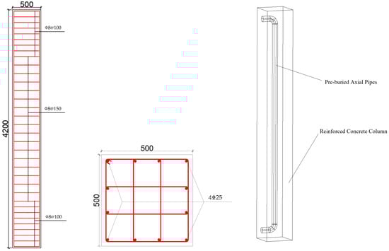
Figure 1.
Specimen dimensions and reinforcement details.
2.2. Material Constitutive Model
2.2.1. Concrete Constitutive
This study employs the Concrete Damaged Plasticity (CDP) model in ABAQUS for numerical simulation analysis. The CDP model reduces the elastic stiffness matrix of concrete by introducing damage factors, representing a composite constitutive model that combines plasticity theory with linear damage mechanics. The CDP model primarily considers two failure modes of concrete: crushing failure under compression and cracking failure under tension. The constitutive relationship follows the stress–strain curves for tension and compression as outlined in Appendix C of the “Code for Design of Concrete Structures” (GB50010-2010) [25], as shown in Figure 2.
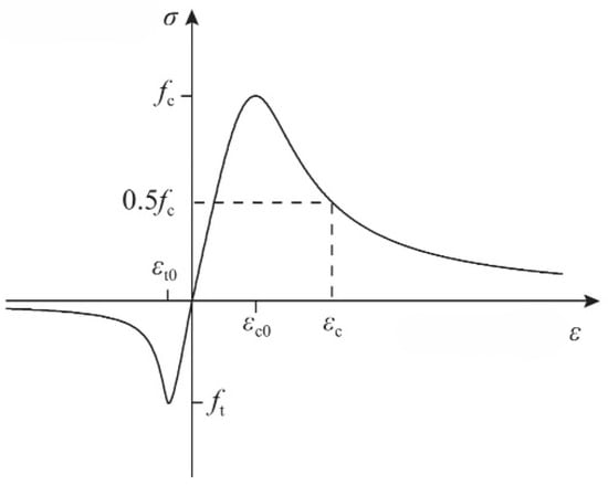
Figure 2.
Stress–strain curve of concrete.
The stress–strain curve for concrete under uniaxial compression is determined according to Equations (1) and (2):
- where ; ; .
- where —the characteristic value of the uniaxial compressive strength of concrete;
—the peak compressive strain of concrete corresponding to ;
—the parameter defining the descending branch of the uniaxial compressive stress–strain curve of concrete;
—the damage evolution parameter for concrete under uniaxial compression.
The stress–strain curve for concrete under uniaxial tension is determined according to Equations (3) and (4):
- where ; .
- where —the characteristic value of the uniaxial tensile strength of concrete;
—the peak tensile strain of concrete corresponding to ;
—the parameter defining the descending branch of the uniaxial tensile stress–strain curve of concrete;
—the damage evolution parameter for concrete under uniaxial tension.
The remaining parameters of the CDP model are listed in the Table 3, where φ represents the dilation angle, e denotes the eccentricity of the plastic potential function, fb0/fco is the ratio of biaxial to uniaxial compressive strength, K is the ratio of the second stress invariant on the tensile meridian to that on the compressive meridian, and μ signifies the viscosity parameter. These parameters are crucial for characterizing the plastic flow, failure surface, and damage evolution of concrete within the CDP model.
Table 3.
Additional parameters of the CDP model.
2.2.2. Constitutive Reinforcement
The constitutive relationship of the reinforcement is modeled using a simplified bilinear ideal elastoplastic model. The stress–strain relationship is illustrated in Figure 3. In the simulation, the elastic modulus and Poisson’s ratio of the reinforcement are determined according to reference [22].
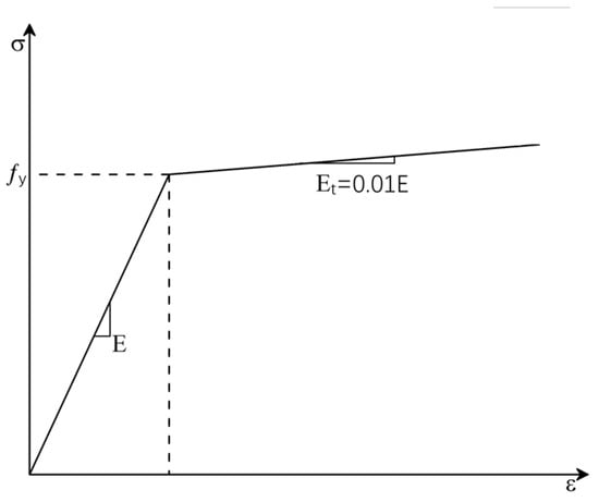
Figure 3.
Stress–strain curve of reinforcement.
The stress–strain curve expression of reinforcement is shown in Equation (5):
where .
2.3. Element Selection and Mesh Division
This study employs the Static-General solution module for numerical simulation analysis. In the modeling process, both concrete and rigid pads are modeled using eight-node reduced integration three-dimensional solid elements (C3D8R), while steel reinforcements are modeled with three-dimensional two-node truss elements (T3D2). The structured meshing technique is adopted to discretize the computational model. Considering the significant influence of the mesh size on computational accuracy, solution efficiency, and convergence behavior, a systematic mesh sensitivity analysis was conducted. The mesh sizes were ultimately determined to be 50 mm for both concrete and rigid pads and 40 mm for steel reinforcements.
2.4. Contact and Boundary Conditions
An embedded region constraint is applied between the reinforcement and the concrete, neglecting the bond–slip interaction between them. To avoid localized stress concentration, a rigid pad is placed at both the top and bottom ends of the column. The rigid pads are constrained to the concrete columns using the Tie command. The upper rigid pad is coupled to the reference point RP1, constraining all degrees of freedom except for the displacement along the column’s longitudinal axis (z-direction). The lower rigid pad is coupled to the reference point RP2, constraining all degrees of freedom of RP2. Displacement loading is applied to the reference point RP1.
2.5. Finite Element Model Verification
To verify the reliability of the finite element analysis model, this study conducted numerical simulation validation using specimen L30-600 from reference [26]. The numerical simulation yielded an ultimate bearing capacity of 16,440 kN, which is 6.35% higher than the experimentally measured value of 15,458 kN reported in the literature. This discrepancy primarily arises from the assumption of perfect bonding between concrete and reinforcement in the simulation, neglecting the actual relative slip behavior between the two materials. Nevertheless, the 6.35% deviation falls within the acceptable margin of error, demonstrating that the established finite element model exhibits good reliability. Furthermore, these validation results provide indirect evidence that the constitutive relationship employed in this study can reasonably describe the mechanical behavior of reinforced concrete structures.
To investigate the influence of longitudinal pre-embedded holes on the mechanical performance of reinforced concrete columns, a finite element modeling approach was adopted. Several groups of finite element analysis models were established, considering different pre-embedded hole diameters, concrete strength grades, stirrup ratios, and slenderness ratios (as shown in Figure 4). These models were used to analyze the failure process of reinforced concrete columns with longitudinal pre-embedded holes under compressive loading. The study aimed to determine the effects of the aforementioned factors on the compressive load-bearing capacity of the columns. The main test specimen parameters and results are shown in Table 4.
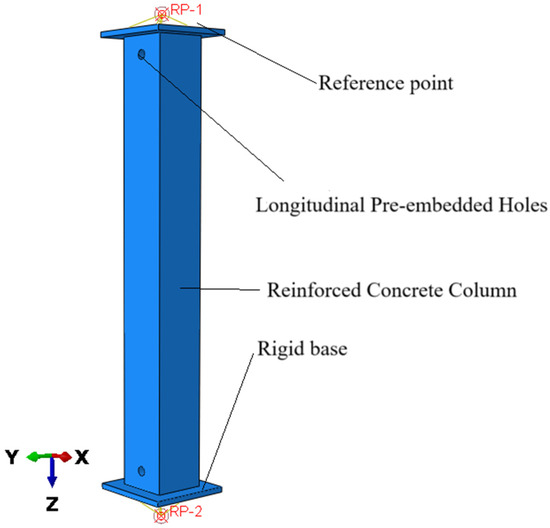
Figure 4.
Specimen model.
Table 4.
Main test specimen design parameters and results.
3. Results and Discussion
3.1. Failure Mode and Phenomenon
Figure 5 and Figure 6 illustrate the distribution of concrete plastic strain and the stress contours of reinforcement, respectively, for a reinforced concrete column without longitudinal pre-embedded holes during the failure process. The figures reveal typical failure characteristics under axial compression. In the initial loading stage, the specimen operates in the elastic phase, with the reinforcement and concrete working in unison to bear the load. The overall deformation is minimal, and the material strain levels are low, with no noticeable changes on the specimen’s surface. As the load continues to increase, the specimen enters the elastoplastic phase, and noticeable bulging deformation begins to appear in the mid-region. With further deformation, the local bulging becomes more pronounced, the concrete cover gradually crushes and spalls, and the longitudinal reinforcement reaches its yield strength, ultimately leading to the failure of the specimen. This failure process vividly reflects the progressive failure characteristics of reinforced concrete columns under axial compression.
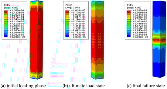
Figure 5.
Equivalent plastic strain cloud image of specimen D0-C30-S1-L8.2.
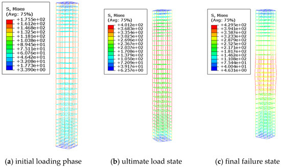
Figure 6.
Reinforcement stress contour plot for specimen D0-C30-S1-L8.2.
Figure 7 and Figure 8 present the stress distribution of a reinforced concrete column with longitudinal pre-embedded holes during the loading process. From the figures, it can be observed that in the initial loading stage, the reinforcement on the side near the hole bears the load first, while the stress in the concrete adjacent to the hole increases significantly faster than in other regions. As the load gradually increases, the stress concentration phenomenon becomes more pronounced, causing the concrete around the hole to exceed its ultimate bearing capacity and fail first. At this stage, the reinforcement surrounding the hole has not yet reached its yield strength. Subsequently, as the load continues to increase, the damaged area of the concrete expands and gradually extends toward the mid-section of the specimen. Ultimately, the failure mode of the specimen resembles that of an ordinary concrete column, with noticeable bulging in the mid-region, complete crushing of the concrete, and the reinforcement reaching its yield strength, leading to the overall failure of the specimen.
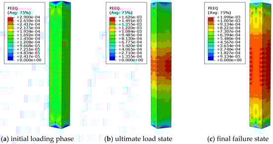
Figure 7.
Equivalent plastic strain cloud image of specimen D50-C30-S1-L8.2.
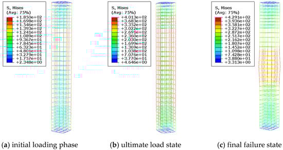
Figure 8.
Reinforcement stress contour plot for specimen D50-C30-S1-L8.2.
As shown in Figure 9, Figure 10, Figure 11 and Figure 12, the failure mode of reinforced concrete columns with longitudinal pre-embedded holes undergoes significant changes as the diameter of the embedded pipes increases. In the initial loading stage, the presence of holes weakens the cross-sectional area, leading to pronounced stress concentration around the perforations. This causes the concrete in the perforated region to reach its ultimate compressive strength and fail first. After the failure of the perforated region, its load-bearing capacity decreases, and the load begins to transfer to the non-perforated side, resulting in an uneven stress distribution. At this stage, the concrete and reinforcement on the non-perforated side bear greater pressure, and the column’s stress state transitions from axial compression to eccentric compression.
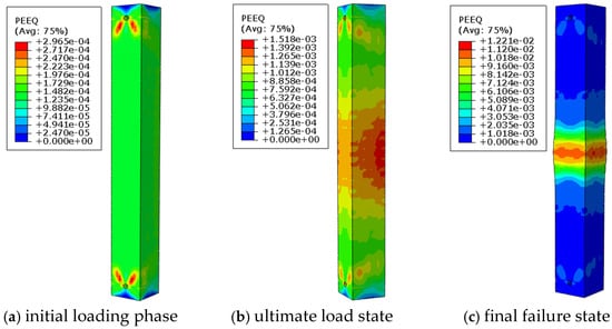
Figure 9.
Equivalent plastic strain cloud image of specimen D75-C30-S1-L8.2.
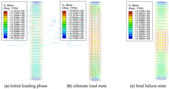
Figure 10.
Reinforcement stress contour plot for specimen D75-C30-S1-L8.2.
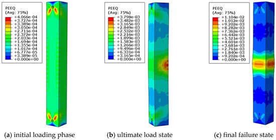
Figure 11.
Equivalent plastic strain cloud image of specimen D90-C30-S1-L8.2.
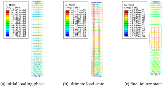
Figure 12.
Reinforcement stress contour plot for specimen D90-C30-S1-L8.2.
As the load continues to increase, the concrete and reinforcement on the non-perforated side gradually enter the plastic stage, leading to further deformation of the column and a gradual reduction in the eccentric compression effect. Ultimately, the load is gradually shared by the entire cross-section. Due to stress redistribution and the ductility of materials, the pre-embedded hole concrete column fails in a manner characteristic of axial compression.
As shown in Figure 13 and Figure 14, when the concrete strength increases to C35 and the pre-embedded hole diameter is 75 mm, the reinforced concrete column with pre-embedded holes experiences shear failure in the perforated region. This phenomenon can be attributed to the significant improvement in the overall compressive performance of the column due to the increased concrete strength. However, the stress concentration effect around the holes becomes more pronounced, leading to a substantial increase in shear stress in the vicinity of the holes, which ultimately triggers shear failure.
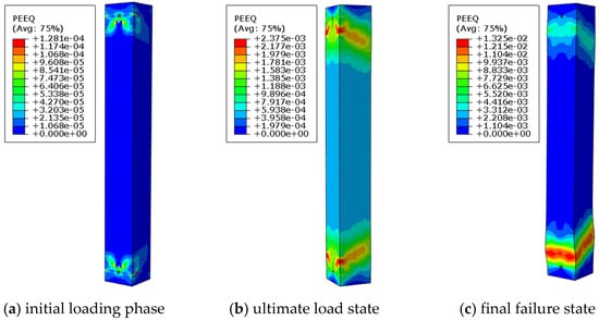
Figure 13.
Equivalent plastic strain cloud image of specimen D75-C35-S1-L8.2.
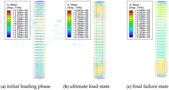
Figure 14.
Reinforcement stress contour plot for specimen D75-C35-S1-L8.2.
As shown in Figure 15 and Figure 16, increasing the stirrup ratio in reinforced concrete columns with pre-embedded holes improves their failure mode, transitioning from shear failure in the perforated region to axial compression failure. This improvement can be attributed to the enhanced shear resistance provided by the higher stirrup ratio, which alters the stress distribution and concentration patterns. By mitigating localized stress concentrations, the increased stirrup ratio prevents shear failure caused by excessive stress around the holes, leading to a more uniform stress distribution and a ductile axial compression failure mode.
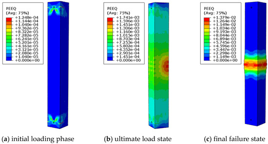
Figure 15.
Equivalent plastic strain cloud image of specimen D75-C35-S2-L8.2.
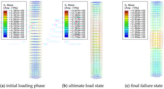
Figure 16.
Reinforcement stress contour plot for specimen D75-C35-S2-L8.2.
3.2. Bearing Capacity Analysis
3.2.1. Impact of Pre-Embedded Hole Diameter on the Bearing Capacity of Reinforced Concrete Columns with Embedded Pipes
The load–displacement curves of all specimens are shown in Figure 17. The load–displacement behaviors of all specimens are almost identical. Compared with the reinforced concrete columns without embedded holes, the ultimate bearing capacity of the reinforced concrete columns with embedded holes decreases to varying degrees. As the embedded hole diameter increases, both the peak ultimate bearing capacity and peak displacement of the curves decrease. Specifically, for embedded hole diameters of 50 mm, 75 mm, and 90 mm, the ultimate bearing capacity decreases by 1.76%, 2.22%, and 3.47%, respectively, compared to the corresponding columns without embedded holes. This is primarily because the presence of the embedded pipes reduces the effective load-bearing area of the frame column cross-section. As a result, the reinforced concrete columns with embedded holes are more prone to entering failure conditions under axial loads, leading to a decrease in bearing capacity.
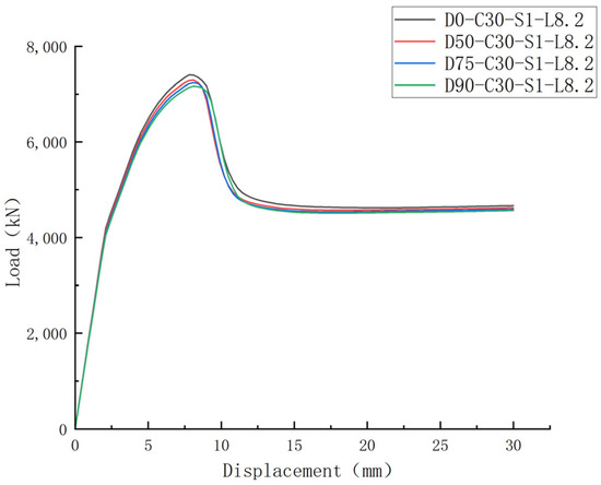
Figure 17.
Impact of hole diameter on load–displacement curve of columns with longitudinal pre-embedded holes.
3.2.2. Impact of Concrete Strength on the Bearing Capacity of Reinforced Concrete Columns with Pre-Embedded Holes
As shown in Figure 18, when the aperture of the longitudinal pre-embedded holes is smaller (50 mm), with the increase in concrete strength of the specimen, the curve slope of the elastic stage becomes larger, the stiffness of the specimen increases, and the ultimate bearing capacity of the specimen also increases with the increase in the concrete strength. Compared with the specimen D50-C30-S1-L8.2, the axial ultimate bearing capacity of specimens D50-C35-S1-L8.2, D50-C40-S1-L8.2, and D50-C50-S1-L8.2 increased by 10.16%, 21.49% and 39.83%, respectively, while that of specimen D50-C25-S1-L8.2 decreased by 11.40%. However, the ultimate displacement of the specimen column decreases with the increase in concrete strength. This is mainly due to the increase in concrete strength, alongside the increase in the elastic modulus and compressive strength of concrete, and, at the same time, the stress concentration phenomenon at the opening of the pre-embedded hole becomes more significant, resulting in the test column entering the ultimate bearing capacity state in advance, and then the ultimate displacement of the test column reaching the ultimate bearing capacity decreases.
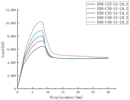
Figure 18.
Impact of concrete strength on load–displacement curve of columns with longitudinal pre-embedded holes.
3.2.3. Impact of Stirrup Ratio on the Bearing Capacity of Reinforced Concrete Columns with Pre-Embedded Holes
As shown in Figure 19, the bearing capacity of the longitudinal pre-embedded hole reinforced concrete columns increases with an increase in the stirrup ratio. For specimens with opening diameters of 50 mm, 75 mm, and 90 mm, when the stirrup ratio increased from 1.04% to 1.63%, the ultimate bearing capacities rose from 7291.99 kN, 7239.18 kN, and 7163.81 kN to 7541.62 kN, 7492.84 kN, and 7432.91 kN, respectively. This corresponds to respective increases of 3.42%, 3.50%, and 3.76%. This phenomenon can primarily be attributed to the enhanced confinement effect provided by the stirrups as their ratio increases, which delays the propagation of shear cracks. Consequently, this improves the shear-bearing capacity around the opening, strengthens the confinement of the core concrete, alleviates stress concentration at the opening edges, and effectively enhances the overall bearing capacity of the column. Furthermore, the larger the diameter of the embedded hole, the greater the improvement in ultimate bearing capacity achieved by increasing the stirrup ratio. This is mainly because a larger embedded hole diameter leads to more pronounced section weakening and stress concentration effects, which are mitigated more effectively by an increased stirrup ratio. Additionally, as the opening hole diameter increases, the redistribution of internal forces becomes more significant. Increasing the stirrup ratio optimizes the internal force distribution, and reduces local stress concentrations and failure risks caused by the opening holes, thereby enhancing the bearing capacity of the column more effectively.
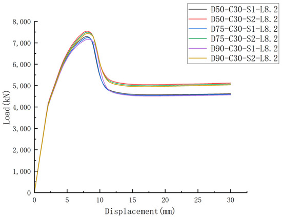
Figure 19.
Impact of stirrups on load–displacement curve of columns with longitudinal pre-embedded holes.
3.2.4. Impact of Slenderness Ratio on the Bearing Capacity of Reinforced Concrete Columns with Pre-Embedded Holes
As shown in Figure 20, when the slenderness ratio of the longitudinal pre-embedded hole reinforced concrete column increases from 6.2 to 12.2, the axial compressive ultimate bearing capacity of the column exhibits only a minor fluctuation. Specifically, compared with λ = 8.2, the ultimate bearing capacity of the specimen with λ = 12.2 decreases by merely 0.41%, while that of the specimen with λ = 6.2 increases by only 0.31%. These findings suggest that within this range, the slenderness ratio has a negligible effect on the bearing capacity of the embedded hole column. This can primarily be attributed to the fact that, within a certain range of slenderness ratios, the bearing capacity is predominantly governed by the effective cross-sectional area and material strength. Given that the diameter of the embedded hole is 50 mm, the extent of section weakening is limited, thus keeping the effective bearing area of the cross-section essentially constant. Moreover, the failure mode of the embedded hole column remains unchanged as the slenderness ratio increases, characterized by typical axial compression failure without any instability-related failure. Consequently, variations in the slenderness ratio have minimal influence on the ultimate bearing capacity of the column.
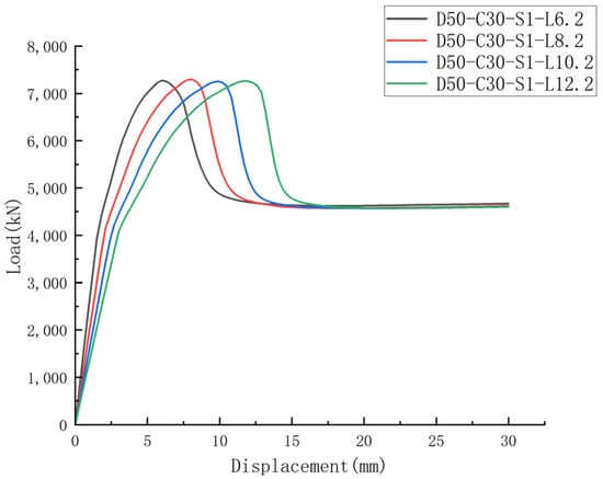
Figure 20.
Impact of slenderness ratio on load–displacement curve of columns with longitudinal pre-embedded holes.
4. Ductility
The ductility coefficient of the reinforced concrete column is an important index for measuring the plastic deformation capacity. It reflects the member’s ability to undergo deformation without sudden failure after reaching its ultimate bearing capacity. The ductility coefficient is usually expressed by the displacement ductility coefficient, which is the ratio of the displacement of the column at the time of failure to the yield displacement. The calculation formula is shown in Equation (6), and the displacement ductility coefficient of each specimen column is shown in Table 5.
where —the displacement of the member when it reaches the ultimate bearing capacity;
Table 5.
Displacement ductility coefficient of each specimen column.
—the displacement of a member at yield strength.
As can be seen from Figure 21, the ductility coefficient of the specimen gradually decreases with the increase in the diameter of the opening hole. Compared with the solid column, the ductility coefficient of the longitudinally pre-embedded hole reinforced concrete column decreases by 3.2~3.6%, but the decrease is small and within the allowable range of the project. The higher the concrete strength of the specimen, the more the ductility of the specimen decreases in significance. According to Figure 18, as the strength of the concrete increases, the decreasing section of the load–displacement curve becomes steeper, which indicates that the ductility is lower. This is mainly because as the strength of the concrete increases, the ultimate compressive strain of the concrete decreases, and the brittleness of the material increases, which limits the overall deformation ability of the column, resulting in a ductility decline of the specimen. With the increase in the stirrup ratio of the specimen, the ductility coefficient of the specimen also increases, mainly because the stirrup can effectively limit the transverse expansion of the concrete, delay the crushing and crack expansion of the concrete, improve the ultimate compressive strain of the concrete, and effectively improve the stress distribution in the area of the embedded hole, reduce the stress concentration around the hole, and delay the development of cracks. However, when the slenderness ratio of the column increases, the ductility coefficient of the specimen shows a downward trend, which is mainly because the increase in the slenderness ratio reduces the stability of the column and leaves it more prone to instability failure, thus weakening the overall deformation ability. In addition, the second-order effect of the column will be increased, further accelerating the stiffness degradation and failure of the specimen column, resulting in the decline of the ductility of the column.
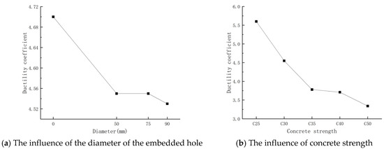
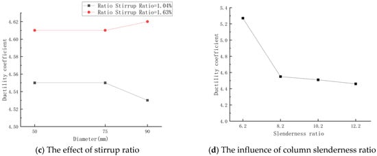
Figure 21.
Influence curves of different factors on the ductility coefficient of longitudinally pre-embedded hole reinforced concrete columns.
5. Conclusions
- (1)
- The inclusion of longitudinal pre-embedded holes in reinforced concrete columns leads to a reduction in their ultimate load-bearing capacity. When the diameters of the pre-embedded holes are 50 mm, 75 mm, and 90 mm, the ultimate load-bearing capacity of the specimens decreases by 1.76%, 2.22%, and 3.47%, respectively. This reduction becomes more pronounced as the diameter of the pre-embedded holes increases. The primary reason for this trend is that the presence of pre-embedded holes reduces the effective load-bearing area of the column cross-section, leaving the column more susceptible to entering failure conditions under axial loading.
- (2)
- When the diameter of the embedded hole is ≥75 mm, the presence of the hole alters the stress state of the reinforced concrete column under axial loading. The column experiences an eccentric compression effect due to the hole. However, through stress redistribution and the material’s ductility, the impact of the eccentric compression gradually diminishes. Ultimately, the failure mode does not undergo a fundamental change and remains dominated by axial compression failure. This indicates that, while the embedded hole affects the stress state, the overall failure mechanism of the column does not undergo a fundamental change due to the presence of the hole.
- (3)
- When the concrete strength exceeds C30, the diameter of the embedded hole should not exceed 50 mm. However, if the hole diameter increases to 75 mm or above and the strength of the concrete reaches C35 or above, the existence of the embedded hole will cause the failure mode of the concrete column to change from axial compression failure to shear failure along the plane where the curved part of the embedded hole is located.
- (4)
- Increasing the stirrup ratio can effectively improve the performance of reinforced concrete columns with embedded holes. As the stirrup ratio increases, both the load-bearing capacity and ductility of the specimens are enhanced, and the stress concentration is reduced, which helps mitigate the risk of local shear failure.
- (5)
- With the gradual increase in slenderness ratio, both the ultimate bearing capacity and ductility of the column show a decreasing trend, but the change amplitude of the ultimate bearing capacity of the column is not significant and can be ignored. The ductility of the specimen column is more obvious with the increase in the slenderness ratio. This indicates that the slenderness ratio has limited influence on the performance of reinforced concrete columns with embedded holes in practical engineering applications, but its potential influence should still be considered in the design to ensure the safety and reliability of the structure.
- (6)
- In practical engineering, the technology of longitudinally pre-embedded hole reinforced concrete columns demonstrates significant advantages, supporting its use in future frame structures and temporary buildings. Optimizing the cross-sectional design reduces self-weight and saves materials, offering considerable economic benefits. Additionally, the innovative multi-functional hole design improves the utilization efficiency of the holes, significantly enhancing the building’s life cycle benefits and reducing its carbon emissions over the entire lifespan. This provides an innovative solution for the development of green buildings.
Author Contributions
Conceptualization, J.Z. and J.Y.; Methodology, J.Y.; Software, J.Z.; Validation, W.X.; Formal analysis, X.L.; Investigation, W.X. and X.L.; Data curation, W.X.; writing—original draft preparation, J.Z.; writing—review and editing, J.Y.; Visualization, W.X. All authors have read and agreed to the published version of the manuscript.
Funding
This research received no external funding.
Institutional Review Board Statement
Not applicable.
Informed Consent Statement
Not applicable.
Data Availability Statement
The data used in this study can be obtained from the corresponding authors.
Acknowledgments
The authors want to thank the editor and anonymous reviewers for their valuable suggestions for improving this paper.
Conflicts of Interest
The authors declare no conflicts of interest.
References
- Xie, X. Development and Prospect of Demolition Blasting Technology. Blasting 2019, 36, 1–12. [Google Scholar] [CrossRef]
- Ye, J.; Cheng, D.; Shu, D.; Li, X.; Ming, J. Green Demolition Blasting Technology for Axially Embedded Holes in Reinforced Concrete Members. Sci. Technol. Eng. 2017, 17, 151–157. [Google Scholar]
- Ye, J.; Cheng, D.; Zhan, X.; Ming, J.; Xiao, H. Blasting Technology of Demolition of Pit-support Beams by Pre-buried Axial Pipes Blast Holes. Blasting 2017, 34, 74–79. [Google Scholar]
- Cheng, D.; Ye, J.; Wang, L.; Ming, J. Blasting Demolition Technology for Reinforced Concrete Beam-Column Members with Long Bags for Axial Embedded Holes Using Water Coupling for Precise Loading. Blasting 2018, 35, 107–113. [Google Scholar] [CrossRef]
- Cai, J.; Huang, T.; Li, J. Experimental Study on Reinforced Concrete Simply Supported Beams with Circular Holes in the Abdomen. J. Civ. Eng. 2009, 42, 27–35. [Google Scholar]
- Han, X. Finite Element Analysis of Bending Capacity of Reinforced Concrete Beams with Holes. Master’s Thesis, Kunming University of Science and Technology, Kunming, China, 2014. [Google Scholar]
- Xu, Z.; Yuan, G.; Nie, M.; Qiu, H. Experimental and Theoretical Study on the Bearing Capacity of RC Beams with Holes. Build. Sci. 2016, 32, 1–8. [Google Scholar] [CrossRef]
- Son, K.; Pilakoutas, K.; Neocleous, K. Behaviour of Concrete Columns with Drilled Holes. Mag. Concr. Res. 2006, 58, 411–419. [Google Scholar] [CrossRef]
- Basravi, A. Finite Element Analysis of Reinforced Concrete Column with Longitudinal Hole; Faculty of Civil Engineering, Universiti Teknologi Malaysia: Johor Bahru, Malaysia, 2010. [Google Scholar]
- Lotfy, F.M. Nonlinear Analysis of Reinforced Concrete Columns with Holes. Int. J. Civ. Struct. Eng. 2013, 3, 655–668. [Google Scholar]
- Campione, G.; Cucchiara, C.; Minafò, G. Effects of circular openings on the compressive behaviour of RC columns. Mater. Struct. 2015, 48, 1995–2008. [Google Scholar] [CrossRef]
- Wilson, P.P.; Nair, E.M.S. Investigation on Reinforced Concrete Columns with Holes. Int. Res. J. Eng. Technol. 2017, 4, 1393–1395. [Google Scholar]
- AL-Shaarbaf, I.A.S.; Allawi, A.A.; AlSalim, N.H. Strength of Reinforced Concrete Columns with Transverse Openings. Eng. J. 2017, 23, 114–133. [Google Scholar] [CrossRef]
- Kassim, M.M.; Ahmad, A.S. Strength Evaluation of Concrete Columns with Cross-Sectional Holes. Pract. Period. Struct. Des. Constr. 2018, 23, 04018027. [Google Scholar] [CrossRef]
- Li, Y. Analysis of the Influence of Core Drilling on the Load-Bearing Performance of Reinforced Concrete Axial Compression Columns Using Finite Element Method. Master’s Thesis, Taiyuan University of Technology, Taiyuan, China, 2019. [Google Scholar]
- Negassa, F. Numerical Investigation of Reinforced Concrete Columns with Transverse Holes. Glob. Sci. J. 2020, 8, 4515–4561. [Google Scholar]
- Tahir, F.M.; Shabbir, F.; Ahmad, A.; Ejaz, N. Experimental and Numerical Investigation of Transverse Circular Holes on Load-Carrying Capacity of RC Columns. Iran. J. Sci. Technol. Trans. Civ. Eng. 2020, 45, 683–696. [Google Scholar] [CrossRef]
- Hailu, B.; Goshu, K. Effect of transverse opening on the strength of reinforced concrete column. Asian J. Civ. Eng. 2022, 24, 639–655. [Google Scholar]
- Zhang, Y.; Zhang, S.; Wang, Z. Effects of Holes and the Confining Pressure on the Mechanical Properties of High-Performance Concrete. Iran. J. Sci. Technol. Trans. Civ. Eng. 2024, 1–14. [Google Scholar] [CrossRef]
- Li, L. Study on the Mechanical Properties of Prefabricated Concrete Columns with Different Hole Rates. Master’s Thesis, Anhui University of Architecture, Hefei, China, 2024. [Google Scholar] [CrossRef]
- Liang, J.; Wang, Y.; Zou, W.; Wang, C.; Li, W. Axial compression performance of partially encased concrete columns with web opening. Sci. Rep. 2024, 14, 11853. [Google Scholar] [CrossRef]
- Bassurucu, M.; Yildiz, O.; Kina, C. Seismic Performance Assessment of an RC Building Due to 2023 Türkiye Earthquakes: A Case Study in Adıyaman, Türkiye. Buildings 2025, 15, 521. [Google Scholar] [CrossRef]
- Hu, C.; Hu, L.; Wang, Y.; Yuan, B.; Wang, B. Influence of reinforcement methods on mechanical properties of reinforced concrete beam-column joints. Civ. Eng. 2023, 12, 1485–1492. [Google Scholar] [CrossRef]
- Vanni, N.; Sandro, C.; Fabrizio, G. Nomograms for the pre-dimensioning of RC beam-column joints according to Eurocode 8. Structures 2022, 39, 39958–39973. [Google Scholar]
- GB 50010-2010; Code for Design of Concrete Structures. China Architecture & Building Press: Beijing, China, 2011.
- Du, X.; Fu, J.; Zhang, J. The experimental study on size effect of the large-size reinforced concrete column under axial loading. Civ. Eng. J. 2010, 43 (Suppl. S2), 1–8. [Google Scholar] [CrossRef]
Disclaimer/Publisher’s Note: The statements, opinions and data contained in all publications are solely those of the individual author(s) and contributor(s) and not of MDPI and/or the editor(s). MDPI and/or the editor(s) disclaim responsibility for any injury to people or property resulting from any ideas, methods, instructions or products referred to in the content. |
© 2025 by the authors. Licensee MDPI, Basel, Switzerland. This article is an open access article distributed under the terms and conditions of the Creative Commons Attribution (CC BY) license (https://creativecommons.org/licenses/by/4.0/).