Article

SMILE: Segmentation-Based Centroid Matching for Image Rectification via Aligning Epipolar Lines

Department of Computer Engineering, Keimyung University, Daegu 42601, Republic of Korea
*
Author to whom correspondence should be addressed.
Appl. Sci. 2025, 15(9), 4962; https://doi.org/10.3390/app15094962
Submission received: 10 March 2025 / Revised: 10 April 2025 / Accepted: 16 April 2025 / Published: 30 April 2025

Abstract

:
Stereo images, which consist of left and right image pairs, are often unaligned when initially captured, as they represent raw data. Stereo images are typically used in scenarios requiring disparity between the left and right views, such as depth estimation. In such cases, image calibration is performed to obtain the necessary parameters, and, based on these parameters, image rectification is applied to align the epipolar lines of the stereo images. This preprocessing step is crucial for effectively utilizing stereo images. The conventional method for performing image calibration usually involves using a reference object, such as a checkerboard, to obtain these parameters. In this paper, we propose a novel approach that does not require any special reference points like a checkerboard. Instead, we employ object detection to segment object pairs and calculate the centroids of the segmented objects. By aligning the y-coordinates of these centroids in the left and right image pairs, we induce the epipolar lines to be parallel, achieving an effect similar to image rectification.

1. Introduction

Stereo image matching, which involves pairing left and right images, has traditionally been an important topic in computer vision [1]. Typically, the acquired stereo images need to undergo an image rectification process to be used meaningfully. This image rectification is performed based on precise parameters obtained through camera calibration [2,3,4]. Before delving into this process, it is essential to understand the concept of epipolar geometry [5,6], which is also a crucial concept in computer vision, especially in stereo vision.
The epipole refers to the point where the optical center of one camera is projected onto the image plane of the other camera. In stereo imaging, since the positions of the two cameras differ, the optical center of one camera appears as a point on the image plane of the other camera. Each camera has its corresponding epipole, and the epipole from one camera lies on a specific line in the other camera’s image, which is called the epipolar line. The condition for efficient stereo matching is that the corresponding points between the two images must lie on the epipolar lines. By exploiting this condition, the stereo matching problem can be solved more efficiently.
To perform stereo image matching, it is necessary to compute the epipolar geometry and determine how the epipolar lines appear. This computation requires obtaining precise camera parameters through camera calibration, which are then used to calculate the epipolar geometry. The epipolar lines in the two images are generally neither parallel nor similarly aligned. To make them parallel, image rectification is applied to align the epipolar lines horizontally. This adjustment ensures that the corresponding points in the images lie on the same row, simplifying the matching process and increasing its accuracy. Consequently, rectified stereo images enable the generation of disparity maps and depth maps based on the disparity between the left and right images.
However, the aforementioned process depends on prior camera calibration, which requires specific calibration patterns and multiple images to ensure accuracy. Moreover, image rectification based on calibration parameters involves complex calculations and constraints, often requiring 3D rotations of the images. In this paper, we propose a method that does not require the calibration patterns used in image calibration. Instead, we utilize object detection [7,8,9,10] to segment [11,12] the object pairs in each image and calculate their centroids. By assuming the line connecting the centroids as an epipolar line, we perform a 2D rotation and padding on each image. This adjustment aligns the centroids horizontally and induces epipolar alignment. Subsequently, we extract a disparity map from the stereo images to demonstrate that the proposed method effectively rectifies images without the need for camera calibration or traditional image rectification.
In summary, the key contributions of this paper are as follows:
  • Stereo image alignment without a checkerboard: we propose a novel stereo image alignment method that does not require calibration patterns such as checkerboards, enabling more flexible and practical image alignment.
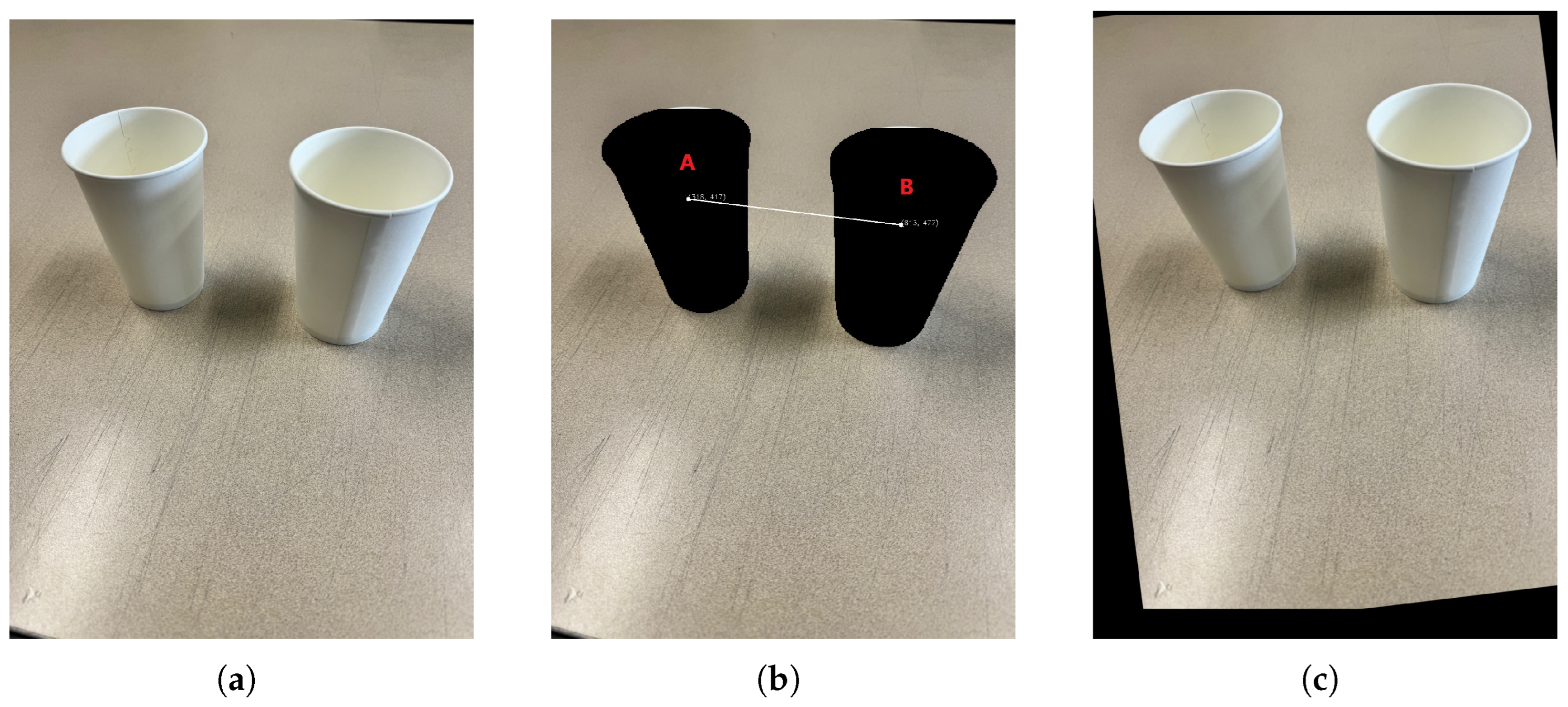
  • Object-based epipolar alignment: without prior camera calibration, we utilize object detection and segmentation to identify object pairs and effectively align epipolar lines horizontally based on the centroids of the detected objects.
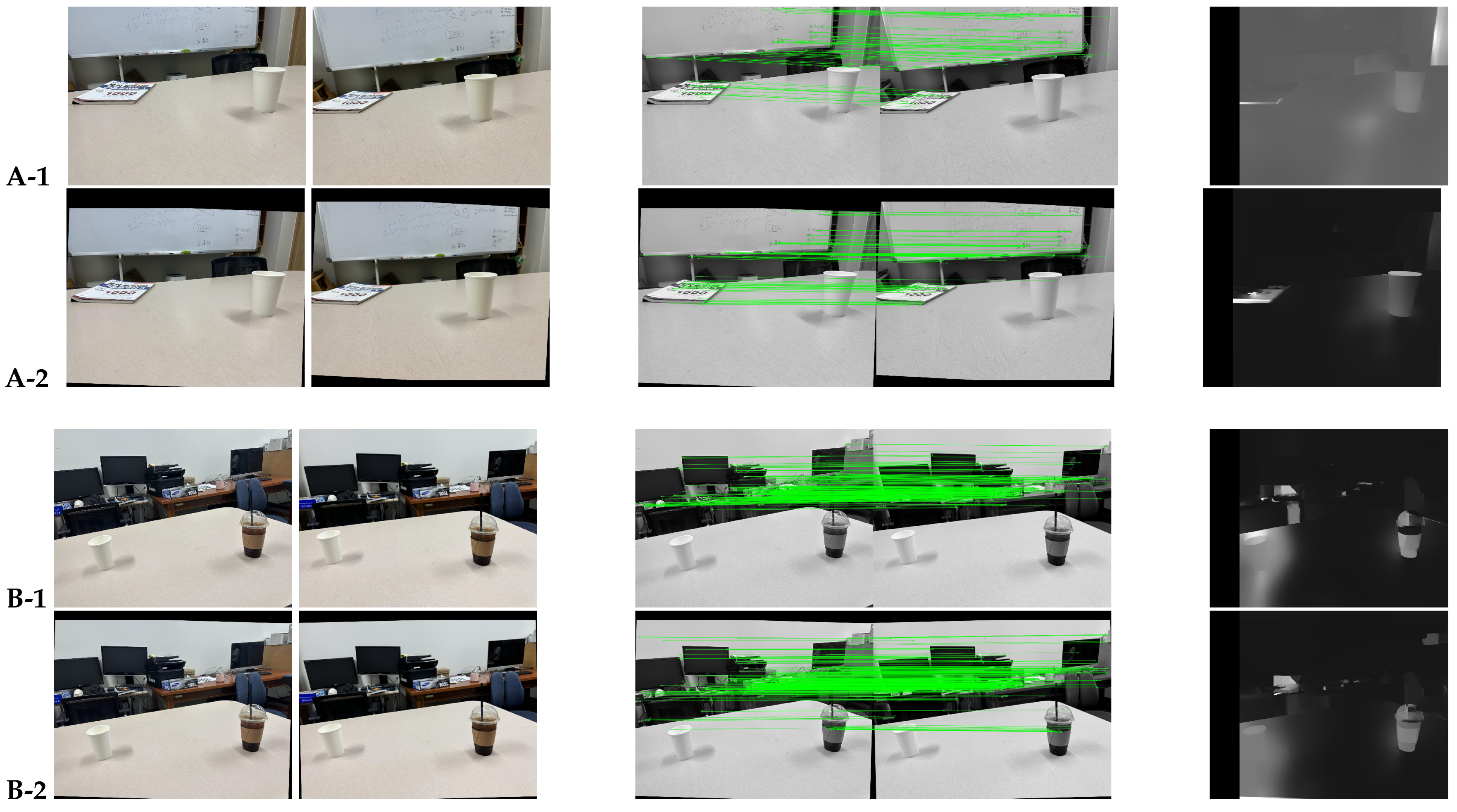
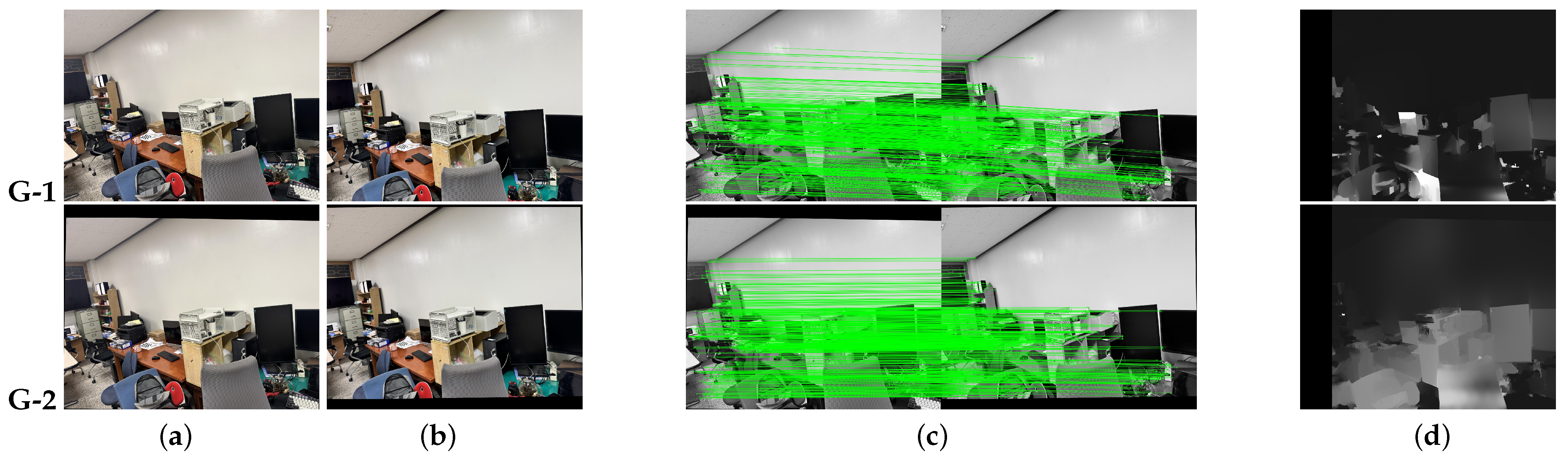
  • Performance evaluation in unstructured capture environments: The image dataset used in this study differs from typical stereo capture environments, as it consists of images taken manually, resulting in irregular Y-coordinate variations. The effectiveness of our approach is verified through various evaluation metrics, including Fundamental Matrix analysis, Y-Disparity, X-Disparity Entropy, SSIM, Feature Matching Accuracy, and Area-based Correlation. Additionally, our method successfully generates disparity maps even for image pairs where disparity map generation was previously unsuccessful, demonstrating its effectiveness.

2. Related Work

2.1. Camera Calibration

In the process of acquiring images, camera lenses can cause distortion [13,14,15,16] during shooting, with radial distortion and tangential distortion frequently occurring, especially with wide-angle lenses. Radial distortion can be further divided into barrel distortion and pincushion distortion. Barrel distortion causes the image to appear magnified as it moves away from the center, while pincushion distortion causes the image to appear compressed towards the center. To remove these distortions, camera calibration [17,18] is necessary. This process involves measuring the camera’s internal and external parameters and is primarily used to correct lens distortion. Camera calibration is the process of finding the parameters that describe the transformation relationship between the 3D space coordinates and 2D image coordinates. The internal parameters of the camera include the focal length, principal point, and skew coefficient. The external parameters of the camera describe the transformation relationship between the camera coordinate system and the real-world coordinate system and include information about the camera’s position and orientation. There are various methods for performing camera calibration, but one of the most common approaches uses calibration patterns [19,20,21], which are geometric patterns such as chessboards or circular patterns. In addition to traditional methods, recent advancements have proposed approaches using deep learning models for camera calibration [22,23,24]. In the case of deep-learning-based methods, camera calibration is performed by training on large amounts of image data to predict camera parameters. The parameters obtained through calibration are then utilized for image rectification.

2.2. Image Rectification

Image rectification [25,26] is particularly useful for aligning images captured by two cameras, such as stereo images, enabling effective 3D reconstruction and depth perception. Therefore, it is used as a useful preprocessing step in fields such as computer vision. Traditionally, image rectification involves aligning the epipolar lines using the parameters obtained from camera calibration. Through this process, the corresponding points in the two images are aligned on the same horizontal line, which greatly reduces computational complexity and minimizes errors, making stereo matching and depth estimation easier. However, with the advent of deep learning models, especially Convolutional Neural Networks (CNNs) [27] that are highly effective in image processing, new methods for image rectification based on deep learning have been proposed [28,29,30,31,32,33,34]. Despite the potential of these deep-learning-based methods, they require a substantial amount of data to train the models adequately and are prone to issues such as overfitting during the rectification process. Additionally, due to the nature of deep learning models, they demand significant computational resources and involve complex calculations, which can be more resource-intensive compared to traditional methods. Despite the challenges, deep learning models are used because they can better handle complex nonlinear distortions, have superior generalization capabilities in various environments and conditions, and show high adaptability to new data, making them potentially more effective than traditional methods. Table 1 summarizes the strengths and limitations of existing algorithms for correspondence point detection.

3. Methodology

The method proposed in this paper is primarily divided into two main tasks: object segmentation and the subsequent rotation and adjustment of the images. Figure 1 summarizes the proposed method.

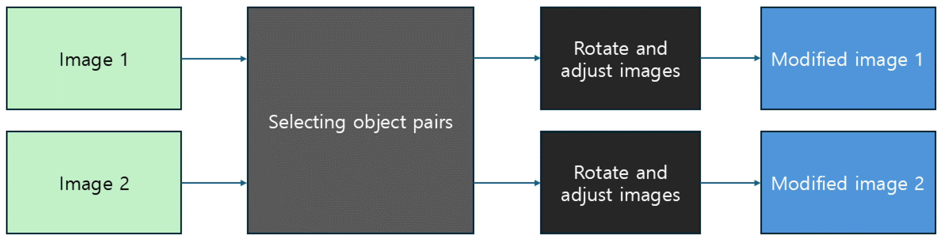
3.1. Selecting Object Pairs

To calculate epipolar geometry, camera calibration is essential. Typically, this calibration process involves using reference points such as checkerboards or patterned objects to obtain the necessary parameters. In this paper, we propose using objects that can be easily identified within images as reference points instead of relying on specific markers like checkerboards. After selecting the object pairs from each image, we mathematically calculate the centroid coordinates of the segmentation masks. The object selection method in this paper is as follows:
  • The class order of the selected object pair (A, B) in Image 1 must match the class order of the selected object pair (A′, B′) in Image 2. (The classes should match exactly: A = A′, B = B′.)
  • The selected object pairs in both images must have the same class and be located in roughly similar positions.
  • Among the object pairs that meet the above conditions, the pair that requires the smallest rotation angle to align the centroid coordinates is selected.
When selecting arbitrary object pairs, the selected objects in Image 1 and Image 2 may differ. This would contradict our objective of achieving a result similar to image rectification by rotating the images based on identical reference points. Therefore, the object pairs selected in Image 1 and Image 2 must be chosen with strict criteria to ensure they are the same. To achieve this, class matching is applied first. Given that there could be many objects in each image, simply selecting object pairs without strict criteria could lead to mismatches in the class of the selected pairs between Image 1 and Image 2. This would indicate that different object pairs were selected. However, even when the object classes match, it does not necessarily mean the same objects were selected as pairs in both images. Without specific reference points, relying solely on object segmentation to set the reference points can be problematic, especially if the input images are everyday images with multiple instances of the same class. Therefore, the selected objects must not only share the same class but also be in similar positions in both images. Finally, among the object pairs that meet these criteria, the pair with the smallest rotation angle difference, based on the differences in their x- and y-coordinates, is selected.
In this paper, the centroids of objects are calculated using the moments derived from the segmented masks of object pairs. The moment M p q of a 2D discrete image is defined as follows:
M p q = x y x p y q I ( x , y )
Here, x and y represent the x-axis and y-axis in the image, respectively, and p and q represent the order of moments for the x-axis and y-axis, respectively. I ( x , y ) is the pixel value at coordinates ( x , y ) . These moments exist in various orders, which are redefined as zeroth- and first-order moments.
The 0th-order moment M 00 represents the sum of all pixel values occupied by the object, corresponding to the area of the object, and is calculated as
M 00 = x y I ( x , y )
The 1st-order moment M 10 with respect to the x-axis represents the moment about the x-coordinate, which is the sum of the products of the x-coordinates and the pixel values of all pixels belonging to the object:
M 10 = x y x · I ( x , y )
Similarly, the 1st-order moment M 01 with respect to the y-axis is expressed as
M 01 = x y y · I ( x , y )
Using the moments calculated from Equations (1) to (4), the centroid coordinates are determined. The centroid here refers to the center of mass of the object as determined by the masked object from object segmentation. The centroid is calculated by dividing the 1st-order moments by the 0th-order moment for both the x- and y-axes.
The x-coordinate of the centroid, c x , is calculated as
c x = M 10 M 00
The y-coordinate of the centroid, c y , is similarly calculated as
c y = M 01 M 00
The process of selecting object pairs from two images is shown in Algorithm 1.
Algorithm 1 Object selection
Input: Two images I 1 and I 2
Output: Best matching object pairs
  • for each image I i ( i = 1 , 2 ) do
  •      Detect objects using YOLOv9-seg model
  •      for each detected object k do
  •          Extract segmentation mask M i k
  •          Calculate moments M 00 , M 10 , M 01
  •          Calculate centroid C i k = ( M 10 / M 00 , M 01 / M 00 )
  •      end for
  •      Store centroids C i and object classes L i
  • end for
  •  Initialize b e s t _ p a i r s = N o n e , θ m i n =
  • for each pair of objects ( a , b ) in I 1 and ( c , d ) in I 2  do
  •      if  L 1 a = L 2 c and L 1 b = L 2 d and positions are similar then
  •          Calculate rotation angles θ 1 , θ 2
  •          if  max ( | θ 1 | , | θ 2 | ) < θ m i n  then
  •             Update θ m i n and b e s t _ p a i r s
  •          end if
  •      end if
  • end for
  • return  b e s t _ p a i r s

3.2. Image Rotation and Adjustment

In the proposed method, the rotation to align the y-values is performed based on the object pairs selected through object segmentation. The object pair used for this rotation is chosen such that the difference in the x-coordinates and y-coordinates between the centroids is minimized, and the pair exists in both images. The centroid coordinates for this object pair are derived from the masks obtained through object segmentation rather than from the bounding boxes typically provided by object detection. This approach yields more accurate centroid coordinates compared to those obtained from bounding boxes.
Using these centroid coordinates, the image can be rotated. To determine the values used for image rotation and adjustment, the rotation angle θ between two points ( x 1 , y 1 ) and ( x 2 , y 2 ) is calculated as follows:
θ = tan 1 y 2 y 1 x 2 x 1
Given that the image center is ( c x , c y ) , the rotation matrix R is computed as
R = cos θ sin θ ( 1 cos θ ) · c x + sin θ · c y sin θ cos θ ( 1 cos θ ) · c y sin θ · c x
The coordinates ( x , y ) of the rotated image are then calculated using
x y = R · x c x y c y + c x c y
Both the rotation angle and rotation matrix are necessary because the rotation angle defines the direction and magnitude of rotation, while the rotation matrix is used to actually perform the rotation. Through this process, the y-coordinates of the centroids of object pairs within each image are aligned to an arbitrary y-coordinate. However, in this case, the y-coordinates are only matched within one image, so a translation must be performed to ensure that the object pairs in both images have the same y-coordinates.
Let ( c x i , c y i ) be the centroid coordinates of image i and c y target be the target y-coordinate for both images. The translation vector T i for image i is then calculated as
T i = 0 c y target c y i
This vector is used to translate all coordinates in the image. After translation, the new coordinates ( x , y ) are computed as
x y = x y + T i
Once these operations have been performed, the sizes of the two stored images need to be made equal. To achieve this, padding is applied to each image. The process of calculating the padding size to match the new height and width is as follows:
P top = H target H i 2
P bottom = H target H i P top
P left = W target W i 2
P right = W target W i P left
Here, H i and W i are the height and width of image i, while H target and W target are the target height and width. P top , P bottom , P left , and P right represent the necessary padding for the top, bottom, left, and right sides, respectively.
The final height H final and width W final after padding are calculated as:
H final = H i + P top + P bottom
W final = W i + P left + P right
H final and W final represent the final computed height and width after padding, which are used to match the sizes of the two images.
The process of rotating and translating the image is shown in Algorithm 2.
Algorithm 2 Image rotation and alignment
Input: Images I 1 , I 2 , and best matching object pairs
Output: Rotated and padded images I 1 , I 2
  • if  b e s t _ p a i r s N o n e  then
  •      for each image I i and pair ( p , q ) in b e s t _ p a i r s  do
  •          Calculate rotation angle θ i and center
  •          Construct rotation matrix R i
  •          Rotate image: I i = a p p l y _ r o t a t i o n ( I i , R i , c e n t e r )
  •          Update centroids C i p , C i q
  •      end for
  •      Calculate target y-coordinate y target
  •      for each rotated image I i  do
  •          Apply translation to align y-coordinates
  •          Update centroids
  •      end for
  •      Calculate target dimensions H target , W target
  •      for each translated image I i  do
  •          Calculate and apply padding
  •          Update centroids
  •      end for
  • end if
  • return Rotated and padded images I 1 , I 2
Figure 2 visually represents the process according to the method proposed in this paper. Figure 2a shows the images used as input; Figure 2b illustrates the results after recognizing the objects within the images, performing segmentation, and calculating their centroids. Figure 2c depicts the result after aligning the y-values based on the calculated object centroids and performing translation.

4. Experiments

In this section, we compare and analyze the preprocessing results using the object-segmentation-based epipolar line parallelization for stereo images proposed in this paper.

4.1. Experimental Environment

The experiments in this study were conducted using data collected by the author. The devices used to capture stereo image data were an iPhone 14 Pro and an iPhone 15 Pro. Object detection and segmentation were performed using the YOLOv9 [35] e-seg object detection model, utilizing a pretrained model. The software environment for the experiments was Python 3.10, and the hardware environment included Windows 11 as the OS, a Ryzen 5 7600X CPU, 32GB of RAM, and an NVIDIA RTX 2070 GPU.

4.2. Experimental Procedure and Evaluation Metrics

The experimental process used stereo image pairs as the input to calculate the center coordinates of the objects in each image through object detection and segmentation. For the object pairs in Image 1 and Image 2, pairs were formed among objects with the same class and similar positions, prioritizing those with the smallest rotation angle, while maintaining the same order of classes between the two images. For the determined object pairs, image rotation, padding, and translation were performed to align the y-coordinates of the object pair’s center points in both images. Subsequently, to verify the effectiveness of the method proposed in the paper, metrics such as the fundamental matrix, Y-disparity, X-disparity entropy, SSIM [36], feature matching accuracy, and area-based correlation were used. Additionally, feature point matching was visualized, and a disparity map was generated for verification.
Typically, when image rectification is performed, the fundamental matrix satisfies the following form:
F = 0 0 0 0 0 1 0 1 0
Looking at Equation (18), the first row and column, the center has a value of 0, which means that displacements in the x-axis and y-axis directions do not affect the epipolar constraint. And, in the 2 × 2 submatrix in the lower right corner, it has values of 0 1 1 0 , showing opposite signs. This indicates a rotation matrix and means that the epipolar lines have become horizontal. The last value may also appear as one, which is a normal phenomenon that can occur due to coordinate system normalization or numerical stability reasons.
Y-disparity measures the difference in the y-coordinates of the corresponding points in stereo image pairs. If rectification is successful, corresponding points should exist at the same y-coordinates, so the Y-disparity value should be close to 0. X-disparity entropy measures the difference in the x-coordinates of the corresponding points in stereo image pairs. If rectification is well performed, the disparity distribution becomes more concentrated, resulting in a lower entropy value. SSIM represents the structural similarity between stereo images, with values closer to one indicating perfect structural similarity. Feature matching accuracy measures the quality of matches between feature points extracted from both images. A value closer to one is better, indicating that more feature points were accurately matched. Area-based vorrelation is an indicator calculated by dividing the images into small regions and then computing the correlation between the two images. A value closer to one is better, signifying high local similarity between the two images. In summary, if the image rectification method proposed in this paper is effective, the Y-disparity and X-disparity entropy should decrease, while the SSIM, feature matching accuracy, and area-based correlation should increase.

4.3. Experimental Results

Conventional camera calibration algorithms utilize precise patterns such as checkerboards to perform feature point detection, matching, and iterative nonlinear optimization. As a result, their computational complexity depends on the number of feature points n, ranging from O ( n ) to O ( n 2 ) in the worst case. In contrast, the proposed SMILE method employs YOLOv9-based object detection, followed by simple 2D transformations—rotation, translation, and padding—applied to each detected object region. These subsequent matrix operations operate linearly with respect to the number of pixels m in the segmented object regions, resulting in a complexity of O ( m ) . In the actual experiments, the average total processing time was measured to be 0.07 s, confirming the feasibility of real-time application even in high-resolution image environments. Furthermore, theoretical FLOPs analysis also indicates that SMILE has lower computational complexity compared to traditional methods.
Figure 3 shows the input images used in the experiments, the visualization of feature point matching, and the resulting disparity maps. These are presented sequentially, first with the original images and then with the images adjusted according to the method proposed in this paper. It can be observed that in the images rotated using the proposed method, the lines connecting the matching points are generally more horizontally aligned compared to the original images. In some cases, disparity maps could not be generated from the original images, but, after applying the proposed rotation and adjustment, disparity maps were successfully generated.
Table 2 shows the evaluation results of the experiment using the fundamental matrix. If the fundamental matrix takes on the value given in Equation (18), it was considered that the rectification was performed accurately. Compared to the original images, after applying the method proposed in this paper, it was observed that in some cases, large values such as one to two were reduced to below one. Overall, the matrix becomes more simplified and the scale of the values is reduced. This indicates that the epipolar geometry was rearranged into a simpler form.
Table 3 shows the average values of Y-disparity, X-disparity entropy, SSIM, feature matching accuracy, and area-based correlation for both the original images without preprocessing and the images processed using the method proposed in this paper. Y-disparity is further divided into Y-disparity mean and Y-disparity Std. For Y-disparity mean, the original images have a value of 34.61, while the images with the proposed rectification applied have a value of 24.79, indicating that the average y-value difference decreased. This suggested that overall alignment improved. Y-disparity Std, which represents consistency in alignment, actually increased from 46.19 to 56.32, implying that the alignment was not consistent. X-disparity entropy showed identical results of 1.31 for both cases, which is likely because the proposed method focuses on rotation based on the y-coordinate, not affecting the X-disparity entropy. The SSIM values are 0.4210 and 0.4412, indicating that the structural similarity becomes closer through the proposed image rectification. Feature matching accuracy decreased slightly from 0.2650 to 0.2599, but the difference was so small that it was likely not significant. Lastly, the area-based correlation values of 0.3616 and 0.3847 indicated that the correlation between the corresponding regions increased when the rectified images were divided into smaller areas. For most metrics, the image rectification method proposed in this paper demonstrates effectiveness without requiring a calibration pattern. It also achieves a fast average processing time of 0.07 s per image. The low computational complexity further highlights its potential for practical applications.

5. Conclusions

In this paper, we propose a new image rectification method using 2D rotation that does not require a calibration pattern, as opposed to image rectification using parameters obtained through camera calibration for stereo images consisting of left and right pairs. The proposed method selects object pairs as reference points in the left and right image pairs, performs segmentation on these object pairs, and then calculates the center coordinates of each object. Subsequently, rotation and adjustment are performed so that the centers of the object pairs have the same y-coordinate values in both images. This aligns the y-values of the object pairs in both images, thereby inducing parallel epipolar lines. The effectiveness of the proposed method is demonstrated through validation using metrics such as the fundamental matrix, Y-disparity, X-disparity entropy, SSIM, feature matching accuracy, and area-based correlation, as well as the visualization of feature point matching and disparity maps. In addition, the fast average processing time of 0.07 s makes it suitable for real-time use even in high-resolution image processing environments, and its low computational complexity indicates strong potential for practical applications. Since this method does not require a calibration pattern, it does not achieve perfect rectification like methods that use patterns. However, when comparing the results before and after processing, it is confirmed that the method effectively improves the outcome. The method proposed in this paper is an image rectification approach that uses objects easily obtainable in nature as reference points, without using reference points such as calibration patterns required for camera calibration. However, this method has limitations in that it may be difficult to apply if there are no objects in the stereo images or if the objects present in the images belong to classes not included in the datasets used to train the object detection models used for object segmentation. Additionally, while strict conditions were set to select the same objects in the left and right images, there may be issues with poor results if different objects are selected or if only objects with large rotation angles are present. In the future, we plan to continue research to perform more accurate image rectification without the need for calibration patterns.

Author Contributions

Conceptualization, J.C. and D.L.; methodology, J.C.; software, J.C.; validation, J.C.; formal analysis, J.C.; investigation, J.C.; resources, D.L.; data curation, J.C.; writing—original draft preparation, J.C.; writing—review and editing, J.C. and D.L.; visualization, J.C.; supervision, D.L.; project administration, D.L.; funding acquisition, D.L. All authors have read and agreed to the published version of this manuscript.

Funding

This research was supported by the Basic Science Research Program through the National Research Foundation of Korea (NRF) funded by the Ministry of Education (No. 2022R1I1A3069352).

Institutional Review Board Statement

Not applicable.

Informed Consent Statement

Not applicable.

Data Availability Statement

All data supporting the findings of this study are included in this article.

Conflicts of Interest

The authors declare no conflicts of interest.

References

  1. Scharstein, D.; Szeliski, R. A taxonomy and evaluation of dense two-frame stereo correspondence algorithms. Int. J. Comput. Vis. 2002, 47, 7–42. [Google Scholar] [CrossRef]
  2. Cao, X.; Foroosh, H. Camera calibration without metric information using 1D objects. In Proceedings of the 2004 International Conference on Image Processing, Singapore, 24–27 October 2004; ICIP’04. IEEE: New York, NY, USA, 2004; Volume 2, pp. 1349–1352. [Google Scholar]
  3. Zhang, Z. Camera calibration with one-dimensional objects. IEEE Trans. Pattern Anal. Mach. Intell. 2004, 26, 892–899. [Google Scholar] [CrossRef] [PubMed]
  4. Zhang, Z. A flexible new technique for camera calibration. IEEE Trans. Pattern Anal. Mach. Intell. 2000, 22, 1330–1334. [Google Scholar] [CrossRef]
  5. Fusiello, A. Tutorial on Rectification of Stereo Images; University of Udine: Udine, Italy, 1998; Available online: https://www.researchgate.net/publication/2841773_Tutorial_on_Rectification_of_Stereo_Images (accessed on 15 April 2025).
  6. Li, S.; Cai, Q.; Wu, Y. Segmenting Epipolar Line. In Proceedings of the 2020 13th International Congress on Image and Signal Processing, BioMedical Engineering and Informatics (CISP-BMEI), Shenyang, China, 17–19 October 2020; IEEE: New York, NY, USA, 2020; pp. 355–359. [Google Scholar]
  7. Zhao, Z.Q.; Zheng, P.; Xu, S.T.; Wu, X. Object detection with deep learning: A review. IEEE Trans. Neural Netw. Learn. Syst. 2019, 30, 3212–3232. [Google Scholar] [CrossRef] [PubMed]
  8. Redmon, J.; Divvala, S.; Girshick, R.; Farhadi, A. You only look once: Unified, real-time object detection. In Proceedings of the IEEE Conference on Computer Vision and Pattern Recognition, Las Vegas, NV, USA, 26 June–1 July 2016; pp. 779–788. [Google Scholar]
  9. Zou, Z.; Chen, K.; Shi, Z.; Guo, Y.; Ye, J. Object detection in 20 years: A survey. Proc. IEEE 2023, 111, 257–276. [Google Scholar] [CrossRef]
  10. Ren, S.; He, K.; Girshick, R.; Sun, J. Faster r-cnn: Towards real-time object detection with region proposal networks. Adv. Neural Inf. Process. Syst. 2015, 28, 91–99. [Google Scholar] [CrossRef] [PubMed]
  11. Li, Y.; Hou, X.; Koch, C.; Rehg, J.M.; Yuille, A.L. The secrets of salient object segmentation. In Proceedings of the IEEE Conference on Computer Vision and Pattern Recognition, Columbus, OH, USA, 23–28 June 2014; pp. 280–287. [Google Scholar]
  12. Gao, M.; Zheng, F.; Yu, J.J.; Shan, C.; Ding, G.; Han, J. Deep learning for video object segmentation: A review. Artif. Intell. Rev. 2023, 56, 457–531. [Google Scholar] [CrossRef]
  13. Claus, D.; Fitzgibbon, A.W. A rational function lens distortion model for general cameras. In Proceedings of the 2005 IEEE Computer Society Conference on Computer Vision and Pattern Recognition (CVPR’05), San Diego, CA, USA, 20–25 June 2005; IEEE: New York, NY, USA, 2005; Volume 1, pp. 213–219. [Google Scholar]
  14. Tang, Z.; Von Gioi, R.G.; Monasse, P.; Morel, J.M. A precision analysis of camera distortion models. IEEE Trans. Image Process. 2017, 26, 2694–2704. [Google Scholar] [CrossRef] [PubMed]
  15. Drap, P.; Lefèvre, J. An exact formula for calculating inverse radial lens distortions. Sensors 2016, 16, 807. [Google Scholar] [CrossRef] [PubMed]
  16. Fitzgibbon, A.W. Simultaneous linear estimation of multiple view geometry and lens distortion. In Proceedings of the 2001 IEEE Computer Society Conference on Computer Vision and Pattern Recognition, Kauai, HI, USA, 8–14 December 2001; CVPR 2001. IEEE: New York, NY, USA, 2001; Volume 1, pp. I-125–I-132. [Google Scholar]
  17. Kim, J.; Bae, H.; Lee, S.G. Image distortion and rectification calibration algorithms and validation technique for a stereo camera. Electronics 2021, 10, 339. [Google Scholar] [CrossRef]
  18. Qi, W.; Li, F.; Zhenzhong, L. Review on camera calibration. In Proceedings of the 2010 Chinese Control and Decision Conference, Xuzhou, China, 26–28 May 2010; IEEE: New York, NY, USA, 2010; pp. 3354–3358. [Google Scholar]
  19. Gao, Z.; Zhu, M.; Yu, J. A novel camera calibration pattern robust to incomplete pattern projection. IEEE Sens. J. 2021, 21, 10051–10060. [Google Scholar] [CrossRef]
  20. Tsai, R. A versatile camera calibration technique for high-accuracy 3D machine vision metrology using off-the-shelf TV cameras and lenses. IEEE J. Robot. Autom. 1987, 3, 323–344. [Google Scholar] [CrossRef]
  21. Heikkila, J.; Silvén, O. A four-step camera calibration procedure with implicit image correction. In Proceedings of the IEEE Computer Society Conference on Computer Vision and Pattern Recognition, San Juan, PR, USA, 17–19 June 1997; IEEE: New York, NY, USA, 1997; pp. 1106–1112. [Google Scholar]
  22. Jin, L.; Zhang, J.; Hold-Geoffroy, Y.; Wang, O.; Blackburn-Matzen, K.; Sticha, M.; Fouhey, D.F. Perspective fields for single image camera calibration. In Proceedings of the IEEE/CVF Conference on Computer Vision and Pattern Recognition, Vancouver, BC, Canada, 17–24 June 2023; pp. 17307–17316. [Google Scholar]
  23. Song, X.; Kang, H.; Moteki, A.; Suzuki, G.; Kobayashi, Y.; Tan, Z. MSCC: Multi-Scale Transformers for Camera Calibration. In Proceedings of the IEEE/CVF Winter Conference on Applications of Computer Vision, Waikoloa, HI, USA, 3–7 January 2024; pp. 3262–3271. [Google Scholar]
  24. Yuan, K.; Guo, Z.; Wang, Z.J. RGGNet: Tolerance aware LiDAR-camera online calibration with geometric deep learning and generative model. IEEE Robot. Autom. Lett. 2020, 5, 6956–6963. [Google Scholar] [CrossRef]
  25. Pritts, J.; Chum, O.; Matas, J. Detection, rectification and segmentation of coplanar repeated patterns. In Proceedings of the IEEE Conference on Computer Vision and Pattern Recognition, Columbus, OH, USA, 23–28 June 2014; pp. 2973–2980. [Google Scholar]
  26. Papadimitriou, D.V.; Dennis, T.J. Epipolar line estimation and rectification for stereo image pairs. IEEE Trans. Image Process. 1996, 5, 672–676. [Google Scholar] [CrossRef] [PubMed]
  27. Li, Z.; Liu, F.; Yang, W.; Peng, S.; Zhou, J. A survey of convolutional neural networks: Analysis, applications, and prospects. IEEE Trans. Neural Netw. Learn. Syst. 2021, 33, 6999–7019. [Google Scholar] [CrossRef] [PubMed]
  28. Yang, S.; Lin, C.; Liao, K.; Zhang, C.; Zhao, Y. Progressively complementary network for fisheye image rectification using appearance flow. In Proceedings of the IEEE/CVF Conference on Computer Vision and Pattern Recognition, Nashville, TN, USA, 20–25 June 2021; pp. 6348–6357. [Google Scholar]
  29. Wang, Y.; Lu, Y.; Lu, G. Stereo rectification based on epipolar constrained neural network. In Proceedings of the ICASSP 2021–2021 IEEE International Conference on Acoustics, Speech and Signal Processing (ICASSP), Virtual Event, 6–11 June 2021; IEEE: New York, NY, USA, 2021; pp. 2105–2109. [Google Scholar]
  30. Liao, Z.; Zhou, W.; Li, H. DaFIR: Distortion-aware Representation Learning for Fisheye Image Rectification. IEEE Trans. Circuits Syst. Video Technol. 2023, 33, 7123–7135. [Google Scholar] [CrossRef]
  31. Hosono, M.; Simo-Serra, E.; Sonoda, T. Self-supervised deep fisheye image rectification approach using coordinate relations. In Proceedings of the 2021 17th International Conference on Machine Vision and Applications (MVA), Nagoya, Japan, 22–25 May 2023; IEEE: New York, NY, USA, 2021; pp. 1–5. [Google Scholar]
  32. Feng, H.; Liu, S.; Deng, J.; Zhou, W.; Li, H. Deep unrestricted document image rectification. IEEE Trans. Multimed. 2023, 26, 6142–6154. [Google Scholar] [CrossRef]
  33. Fan, J.; Zhang, J.; Tao, D. Sir: Self-supervised image rectification via seeing the same scene from multiple different lenses. IEEE Trans. Image Process. 2023, 32, 865–877. [Google Scholar] [CrossRef] [PubMed]
  34. Chao, C.H.; Hsu, P.L.; Lee, H.Y.; Wang, Y.C.F. Self-supervised deep learning for fisheye image rectification. In Proceedings of the ICASSP 2020–2020 IEEE International Conference on Acoustics, Speech and Signal Processing (ICASSP), Barcelona, Spain, 4–8 May 2020; IEEE: New York, NY, USA, 2020; pp. 2248–2252. [Google Scholar]
  35. Wang, C.Y.; Yeh, I.H.; Liao, H.Y.M. Yolov9: Learning what you want to learn using programmable gradient information. arXiv 2024, arXiv:2402.13616. [Google Scholar]
  36. Wang, Z.; Bovik, A.C.; Sheikh, H.R.; Simoncelli, E.P. Image quality assessment: From error visibility to structural similarity. IEEE Trans. Image Process. 2004, 13, 600–612. [Google Scholar] [CrossRef] [PubMed]
Figure 1. Overview of the proposed method.
Applsci 15 04962 g001
Figure 2. Process of rotating an image. (a) Input image, (b) image with calculated center after segmentation, (c) rotated image with computed center.
Applsci 15 04962 g002
Figure 3. Process of stereo image rectification, feature matching, and disparity map generation for different scenes. (a) Left image, (b) right image, (c) feature matching, (d) disparity map. Images with odd numbers are the original images in their initial acquired state, while images with even numbers are the ones to which the method proposed in this paper was applied.
Applsci 15 04962 g003aApplsci 15 04962 g003bApplsci 15 04962 g003c
Table 1. Comparison of existing algorithms for correspondence point detection.
MethodStrengthsLimitations
Traditional Camera CalibrationAccurate estimation of intrinsic/extrinsic parameters using precise patternsRequires calibration patterns
SIFT/SURFRobust to rotation and scale changesHigh computational cost
(especially SIFT),
not suitable for real time
Lightweight feature extractors (e.g., ORB)Low computational cost, suitable for real-time applicationsLower accuracy and precision compared to SIFT/SURF
Deep-learning-based keypoint detectionHigh performance under various conditionsRequires large-scale training datasets
Table 2. Fundamental matrix calculated for Figure 3.
OriginalRectified
A-1A-2
−0.00000.0000−0.0005−0.00000.0000−0.0014
−0.00000.0000−0.0135−0.00000.0000−0.0096
−0.00030.01131.00000.00090.00831.0000
B-1B-2
0.00000.0003−0.15260.00000.0000−0.0003
−0.00040.00001.4253−0.00000.00000.0203
0.1797−1.42801.0000−0.0009−0.02201.0000
C-1C-2
−0.00000.00060.0887−0.00000.00000.0011
−0.00050.0000−2.5343−0.0000−0.0000−0.0373
−0.11142.46341.0000−0.00190.03731.0000
D-1D-2
0.00000.0000−0.00070.0000−0.00000.0080
−0.0000−0.00000.11330.0000−0.0000−0.0448
−0.0004−0.11281.0000−0.00850.04461.0000
E-1E-2
0.00000.0000−0.00110.0000−0.00000.0138
−0.0000−0.00000.0085−0.00000.0000−0.1716
−0.0002−0.00911.0000−0.00150.18081.0000
F-1F-2
0.00000.0002−0.1414−0.0000−0.00000.0025
−0.00020.00000.00040.00000.0000−0.0160
0.1346−0.00461.0000−0.00280.01501.0000
G-1G-2
0.00000.0000−0.0187−0.0000−0.00000.0071
−0.0000−0.00000.07660.00000.0000−0.0313
0.0166−0.07571.0000−0.00570.03051.0000
Table 3. Analysis of results in Figure 3 through metrics.
MetricOriginalProposed
Y-disparity mean34.6124.79
Y-disparity Std46.1956.32
X-disparity entropy1.311.31
SSIM0.42100.4412
Feature matching accuracy0.26500.2599
Area-based correlation0.36160.3847
Disclaimer/Publisher’s Note: The statements, opinions and data contained in all publications are solely those of the individual author(s) and contributor(s) and not of MDPI and/or the editor(s). MDPI and/or the editor(s) disclaim responsibility for any injury to people or property resulting from any ideas, methods, instructions or products referred to in the content.

