Article

Ion-Implanted Diamond Blade Diced Ridge Waveguides in Pr:YLF—Optical Characterization and Small-Signal Gain Measurement

by
Omer Altaher
1,*,
Kore Hasse
1,
Sergiy Suntsov
1,
Hiroki Tanaka
2,
Christian Kränkel
2,
Istvan Bányász
3,
Romana Mikšová
4 and
Detlef Kip
1
1
Faculty of Electrical Engineering, Helmut Schmidt University, Holstenhofweg 85, 22044 Hamburg, Germany
2
Leibniz-Institut für Kristallzüchtung (IKZ), Max-Born-Str. 2, 12489 Berlin, Germany
3
Department of Physics and Chemistry, Széchenyi István University, H-9026 Gyõr, Hungary
4
Nuclear Physics Institute CAS, Hlavní 130, 250 68 Rež, Czech Republic
*
Author to whom correspondence should be addressed.
Appl. Sci. 2025, 15(9), 4956; https://doi.org/10.3390/app15094956
Submission received: 1 April 2025 / Revised: 24 April 2025 / Accepted: 28 April 2025 / Published: 30 April 2025
(This article belongs to the Section Optics and Lasers)

Abstract

:
Planar optical waveguides were fabricated in Pr:YLF crystals by ion implantation. In a further step, ridge waveguides were fabricated using precision diamond dicing. These enable strong light confinement and have propagation losses as low as 0.4 dB/cm. To study the influence of ion implantation on the spectroscopic properties, fluorescence and lifetime measurements were conducted in the ridge waveguides. Under blue pumping, small-signal optical gains of 6.5 dB/cm and 5 dB/cm were demonstrated at wavelengths of 607 nm and 639 nm, respectively. These results make ion-implanted ridge waveguides in Pr:YLF promising candidates for compact integrated lasers in the visible spectral region with high output powers in the watt range.

1. Introduction

Optical waveguides are the basic building blocks of integrated photonics and enable the miniaturization and integration of passive and active optical devices. Various techniques can be used to produce waveguides, among them being femtosecond (fs) laser inscription [1], UV light illumination [2], high-energy ion implantation [3,4,5,6], metal ion in-diffusion [7], and proton exchange [8]. Ion implantation is a unique and relatively universal technique for producing optical waveguides by changing the refractive index (RI) in the surface region of a material. Implanted high-energy ions, both light ions such as protons (H+) and helium (He+) and swift-heavy ions such as silicon (e.g., Si4+) and carbon (e.g., C3+), interact with electrons and/or nuclei in the near-surface region of a material. This can lead to the formation of planar waveguide structures through local RI changes. This technique has been used to create well-defined guiding structures in a variety of crystalline and amorphous materials [4].
Due to their optical transitions in the visible region, crystals doped with rare-earth (RE) ions, e.g., praseodymium, samarium, or europium, have been used as active media for solid-state lasers operating in that spectral region [9,10]. Among these ions, trivalent praseodymium (Pr3+) is of particular interest due to its high absorption cross-section of more than 10−19 cm2 for blue pump light that can be provided by readily available InGaN laser diodes and because its emission spectrum includes several strong lines in the visible region [9,11,12]. First compact Pr3+ waveguide lasers in different host crystals have been successfully demonstrated using fs laser inscription, for example, in SrAl12O19 [13], YLiF4 (YLF) [14,15,16], or LiLuF4 [17]. Furthermore, planar Pr3+ waveguide lasers have been realized by the epitaxial growth of Gd and Lu co-doped YLF layers on YLF substrates [18]. Although these waveguide lasers enabled optical powers in the watt range, there are limitations concerning the photonic integration of fs-laser-written and planar epitaxially grown waveguides. Due to the small RI change, which is typically in the range of 10−4 [19], the minimum bending radius of fs laser-inscribed waveguides is rather limited to centimeters [20], which is much larger than the desired sub-millimeter range. Smaller bending radii could be achieved in ridge waveguides with crystal-to-air interfaces, but such structures cannot be fabricated by diamond blade dicing since this fabrication technique is limited to straight structures. However, they could be fabricated using other methods like chemical mechanical polishing [21], fs laser ablation [22], or (ion beam) etching [23], which is yet to be developed for YLF.
In this work, we report on the fabrication of diamond blade diced ridge waveguides in swift-heavy carbon ion (C3+)-implanted Pr:YLF crystals. The RI changes in the near-surface region were quantitatively investigated for different ion implantation doses. The waveguide propagation losses were characterized for both TE and TM polarized light. Fluorescence spectra and fluorescence lifetime characteristics in the ridge waveguides were investigated and compared to those of a bulk Pr:YLF crystal. Small-signal optical gain at the orange and red fluorescence lines was achieved under pumping waveguides with a frequency-doubled laser at a 444 nm wavelength.

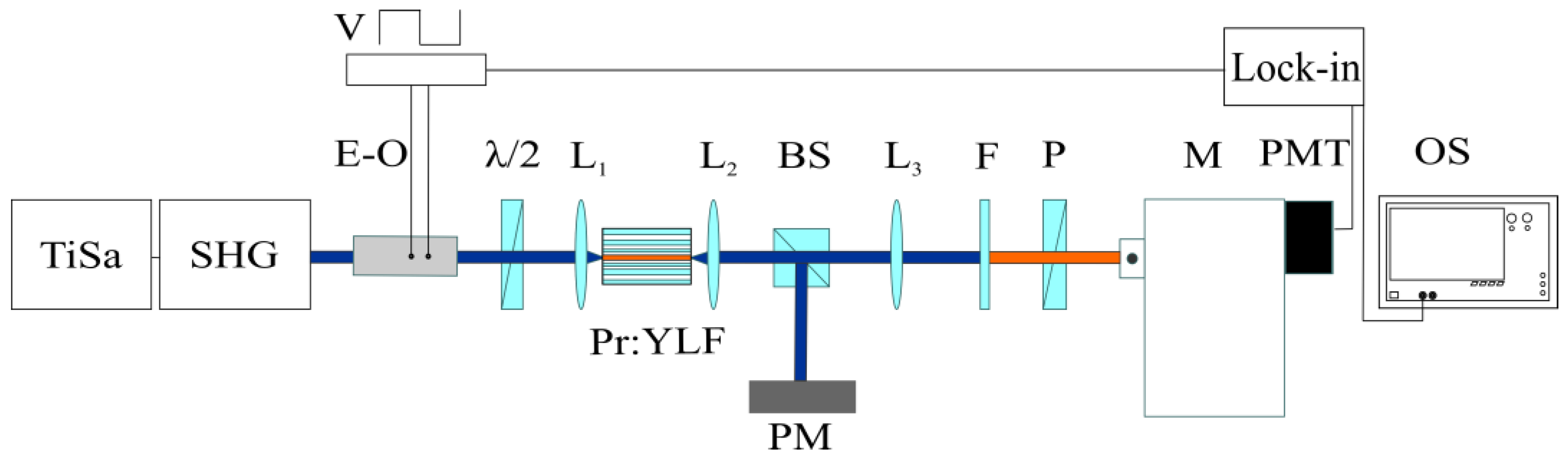
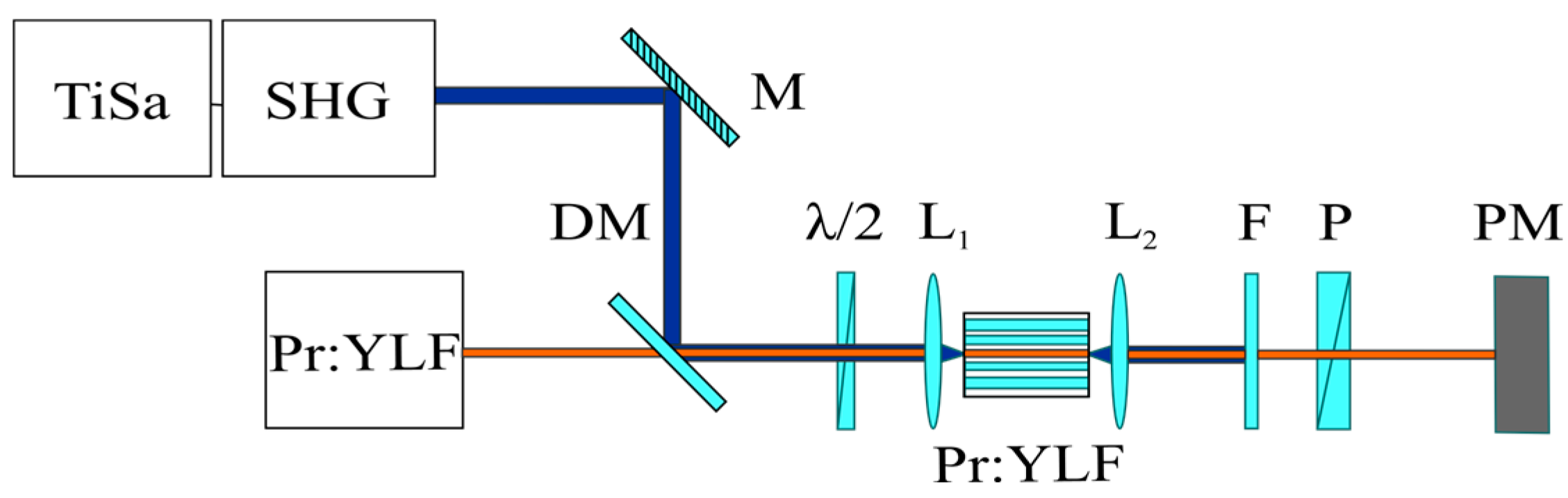
2. Experimental Methods

A YLF crystal doped with 0.5 at.% Pr3⁺ ions was grown using the Czochralski method. Four Pr:YLF a-cut samples with dimensions (a × a × c) of 1 × 14 × 10 mm3 were prepared from this crystal for ion implantation at Tandetron Laboratories in Rež, Czech Republic. YLF is a well-known fluoride crystal that is less susceptible to non-radiative multi-phonon decay and excited-state absorption (ESA) at 5d levels at both pump and laser wavelengths compared to oxide crystals. A beam of carbon ions (C3⁺) with high energies of 10 MeV was used to irradiate the surface of the crystals. The samples were tilted 7° from the normal direction to minimize the ion tunneling effect during implantation. The crystals were implanted with fluences (doses) of 2 × 10¹⁴, 6 × 10¹⁴, 2 × 10¹⁵, and 6 × 10¹⁵ ions/cm2 and labeled Pr:YLF-1 to Pr:YLF-4 with an increasing dose. The effective refractive indices of guided modes of the formed planar waveguides were measured at a wavelength of 532 nm using a prism coupler (Metricon 2010/M) for both TM (σ, ordinary wave, no) and TE (π, extraordinary wave, ne) polarizations. Annealing treatment after ion implantation leads, on the one hand, to a decrease in optical propagation losses through the reduction in ion-induced electronic defects, such as scattering or color centers, but, on the other hand, it can also partially restore the birefringence of uniaxial crystals, which is often reduced before by implantation, to the previous values. The first effect is desirable, but the second should only occur to a limited extent in order not to reduce the waveguiding properties too much. Therefore, the samples were annealed in air at temperatures of up to 250 °C, starting from 100 °C and increasing the temperature stepwise in 50 °C increments, with each temperature being maintained for 30 min. After each annealing step, the prism coupler measurements were repeated until a change in the mode spectrum was observed.
Lateral light confinement was achieved by cutting ridges with a 13–25 µm width, a 15 µm height, and a 14 mm length perpendicularly to the c-axis of the fabricated planar waveguides using a Disco DAD322 precision diamond saw, as described in [14,15]. Since chipping occurs easily during the cutting of YLF, a soft resin-bonded blade (Disco G1A853 SD6000 R21B01) with a 200 µm width was used at 25,000 rpm with a 0.2 mm/s feed speed to cut the ridges. For this reason, the end facets were also prepared with the same blade, making 50 µm deep so-called polishing cuts. We want to note that broader ridge widths were chosen here to achieve a better overlap in future laser and amplifier experiments, where a multimode diode with an astigmatic beam profile is planned to be used for pumping.
Propagation loss measurements in the ridge waveguides were conducted with the transmission method using a helium–neon (HeNe) laser at a 632.8 nm wavelength. The coupling efficiency was estimated by calculating the overlap integral of the transmitted waveguide mode intensity and that of the measured HeNe laser beam focal spot.
For fluorescence measurements, bulk and ridge waveguide samples were excited using a tunable continuous-wave frequency-doubled Ti:sapphire laser (MSquared SolsTiS Doublet, UK). The linearly polarized pump beam was coupled into the ridge waveguides using an aspheric lens (L1, f = 4.5 mm, NA = 0.55), and the transmitted residual pump and the generated fluorescent light were collimated with another lens (L2, f = 20.5 mm, NA = 0.15) at the waveguide end facet, as sketched in Figure 1. After filtering out the residual pump light with a long pass filter with a cut-on wavelength of 450 nm (Thorlabs FELH0450, US), the polarization-resolved fluorescence spectra were recorded with a spectral resolution of 0.05 nm using a monochromator (Bentham IDR300, UK) and a calibrated photomultiplier (Hamamatsu R928, Japan) as a detector. To record the fluorescence spectrum of the bulk Pr:YLF crystal for comparison, the pump beam was injected into the unmodified substrate part of the sample using a weaker lens (L1, f = 14 mm, NA = 0.18).
For the fluorescence lifetime measurements, the pump beam was chopped into rectangular pulses with a trailing edge of 25 ns using an electro-optic modulator (Gsanger Optoelektronik, LM 0202P, Germany). The fluorescence decay was recorded with a temporal resolution of 5 ns using a 500 MHz digital oscilloscope connected to the analog output of the photomultiplier tube (see Figure 1).
As signal light for small-signal gain measurements, laser emission at 607 nm and 639 nm wavelengths from a home-built bulk crystal Pr:YLF laser was used. The low-power signal beam was collinearly combined with the pump beam with a maximum available power of 55 mW using a dichroic mirror, as shown in Figure 2. Both signal and pump beams were coupled into the ridge waveguide. After exiting the ridge, the residual pump light was filtered out with a long-pass filter, and the transmitted power of the signal light was recorded at different pump power levels.

3. Results and Discussion

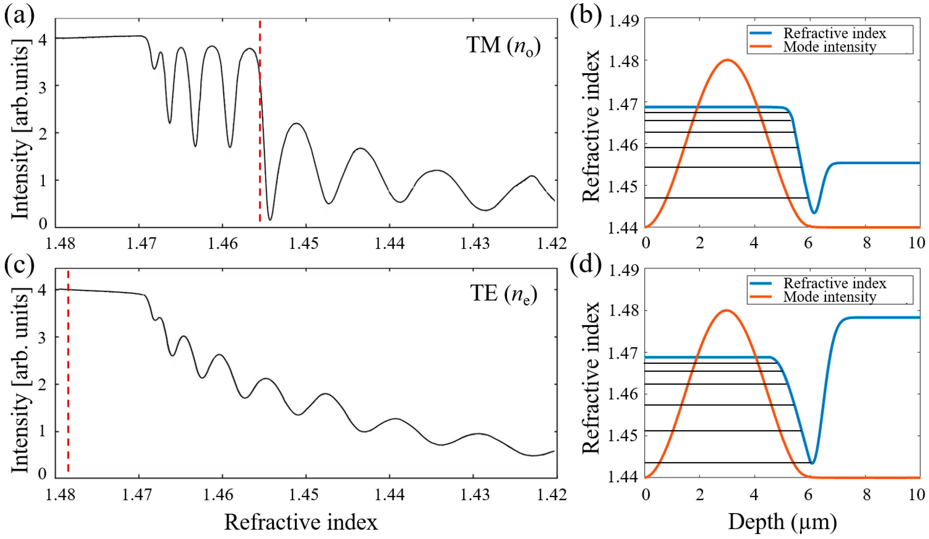
3.1. Planar Waveguide Characterization—Induced Refractive Index Changes

The penetration depth of the ions into the crystal during implantation can be calculated using the ‘Stopping and Range of Ions in Matter’ (SRIM) code [24]. For our implantation parameters, it was found to be approximately 6.5 µm. Implanted ions lead to structural changes, i.e., to electronic defects (in the entire implanted area) and to crystal amorphization due to collisions with nuclei (in a narrow area around 6.5 µm depth), resulting in RI changes that lead to the formation of planar waveguides.
Samples Pr:YLF-1, Pr:YLF-2, and Pr:YLF-3 had similar prism coupler mode spectra, indicating that the measured RI changes for both polarizations already occurred at the lowest implantation dose of 2 × 10¹⁴ ions/cm2 and was quickly saturated for higher doses. The surface of Pr:YLF-4, however, was damaged, presumably due to the high implantation dose, so no guided modes could be excited with the prism coupler in this sample.
The measured mode spectra for TM and TE polarizations for the Pr:YLF-3 sample are shown in Figure 3a and Figure 3c, respectively, as examples. As can be seen, the first four lower-order TM-polarized modes have effective refractive indices neff higher than the respective bulk index no, which is marked with a vertical red dashed line in Figure 3a. The corresponding mode dips are deep and narrow so that good confinement and low waveguide losses are expected. The effective indices of all TE-polarized modes are lower than the bulk index ne; thus, they are guided only due to the formation of a lower-index barrier located at the stopping range [4,5] of implanted C3⁺ ions. In Figure 3c, the TE mode dips are shallower and broader than those for TM polarization, indicating that the TE-polarized modes are relatively weakly guided and lossy.
Since the built-in inverse Wentzel–Kramers–Brillouin (iWKB) solver of the prism coupler could not accurately reconstruct the complex RI profiles containing an optical barrier, a Matlab mode-solver code [25] was used. The RI profiles for TE and TM polarizations with the best match of the calculated mode indices with the measured ones for the first eight modes were found by varying the RI and width of the guiding layer in the simulation as well as the depth and width of the optical barrier (under its Gaussian shape assumption) (see Figure 3b,d). The near-surface RI of the guiding layer was found to be 1.469 for both polarizations, which is 0.012 higher than the no and 0.010 lower than the ne bulk indices [26]. The optical barrier minimum is located at a 6.2 µm depth, which is in good agreement with the SRIM calculation, and its width is slightly larger for TE-polarized light. Also, the barrier RI minima depth increases with the ion dose.
Upon annealing, no significant changes in the waveguiding properties were observed for temperatures of up to 200 °C. After annealing at 250 °C, the mode spectra changed for both polarizations for the Pr:YLF-1 sample with the lowest ion dose, which was the first sample annealed at this temperature. These changes indicate that, although the optical barrier at the ions’ stopping range is still preserved, the crystal structure in the guiding layer starts to return to its original birefringent state. To preserve the waveguiding properties of the Pr:YLF-2 and Pr:YLF-3 samples implanted with higher ion doses, annealing was stopped after the 200 °C step.

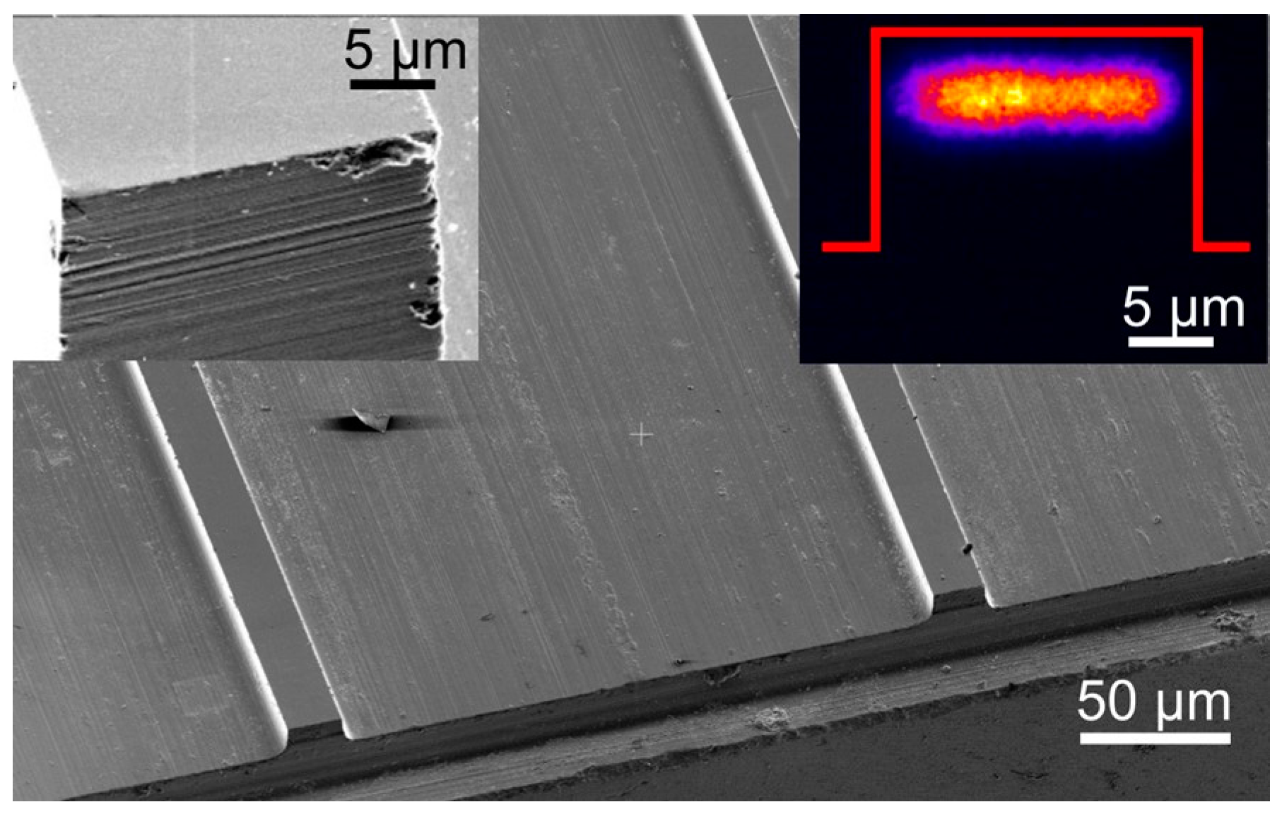
3.2. Ridge Waveguide Characterization

A scanning electron microscope (SEM) image of the ridge waveguides in sample Pr:YLF-3 is shown in Figure 4. The ridges are smooth without chipping and a shape close to a rectangle. However, the polishing cut of the facet, shown in the left inset of Figure 4, reveals a striped pattern, i.e., the end facets as well as the ridge side walls are not as smooth as, e.g., those of the diced LN ridge waveguides [8]. Better surface quality is expected in the future via optimized dicing parameters for YLF. The striped pattern is attributed to blade roughening during cutting. Thus, the choice of a different blade or sandwiching the Pr:YLF sample between two sacrificial LN substrates along the cut direction for dressing and guiding the blade might yield better results.
Waveguiding with good confinement of the guided modes was observed in sample Pr:YLF-3. The waveguides of sample Pr:YLF-2 had higher losses, possibly caused by weaker confinement because of the shallower optical barrier. Thus, only sample Pr:YLF-3 was analyzed with respect to waveguide losses and optical gain. To determine the in-coupled power, the measured incident power was corrected for the Fresnel loss of 0.15 dB at each waveguide facet, and for the coupling efficiency, it was estimated to be between 30% and 40% depending on the ridge width, with higher values for narrower waveguides. Through a comparison with the setup transmission without the sample, the propagation losses were estimated. The inset on the right side of Figure 4 shows a mode guided in a 22 µm wide ridge waveguide. The guided mode is very broad as the waveguide is in multimode in the lateral direction because of the chosen ridge width.
In this way, propagation losses of 0.4–2.9 dB/cm and 6.2–9.5 dB/cm were calculated in Pr:YLF-3 for TM and TE polarizations, respectively. Narrower waveguides had higher loss values for both polarizations, which can be explained by the stronger influence of the side wall roughness on propagation loss for such waveguides. The higher losses for TE-polarized light can be explained by the different guiding mechanisms. As observed during the prism coupler measurements, here, a barrier waveguide is formed. Modes of barrier waveguides naturally leak into the substrate. For TM polarization, the lowest propagation loss of 0.4 dB/cm was found for a 22 µm wide ridge waveguide. Compared to ion-implanted waveguides in other materials, this value is among the lowest reported losses and is comparable to those achieved in titanium-diffused diamond blade diced ridge waveguides or in fs laser-inscribed waveguides [8,19].

3.3. Fluorescence and Lifetime Measurement

In trivalent Pr3+, excitation from the ground-state multiplet 3H4 into the multiplet 3P2 is followed by non-radiative decay into the metastable upper-level 3P0 from which most of the fluorescence lines originate. The fluorescence spectra for both π and σ polarization of sample Pr:YLF-3 in the visible spectral range are shown in Figure 5. Overall, the recorded fluorescence spectra were in good agreement with the spectra reported in the literature [10,27]. However, the π-polarized fluorescence peak at 479 nm of the ridge waveguide and the bulk is lower by a factor of four in comparison to that in the literature, which could be caused by reabsorption. Other small differences compared to the results in the literature may be attributed to amplified spontaneous emission (ASE) due to the long propagation of the fluorescent light in the sample for both waveguide and bulk geometry.
The recorded absolute fluorescence intensity in the waveguides was low for π polarization as a result of the high propagation losses for the TE modes in the ridge. Finally, no significant broadening of the fluorescence peaks was observed in the waveguides compared to the bulk, e.g., the peaks at 639.6 nm and 607 nm for σ polarization have FWHMs of 0.9 nm and 1.2 nm in the bulk and waveguide, respectively. The most significant relative difference in bulk and waveguide spectra is the strong enhancement in the 3H5 peak intensity. The corresponding transition 3P03H5 is partially symmetry-forbidden according to the group theory for Pr3+ on S4 symmetry sites in YLF [28], and the increased peak height (especially for fluorescence within the waveguide) can tentatively be attributed to a reduced site symmetry after ion implantation, which is due to partial amorphization in the implanted surface area [4].
From the measurements of fluorescence decay to 3F2 from the 3P0 level upon excitation into the 3P2 multiplet, lifetimes of 48 µs and 50 µs were obtained for the bulk and the waveguide, respectively. No significant change in the lifetime was observed, and the values are in accordance with the values in the literature [10]. Thus, from both the fluorescence and the lifetime measurement results, the conclusion that ion implantation has no negative effect on the spectroscopic properties of Pr:YLF could be drawn.

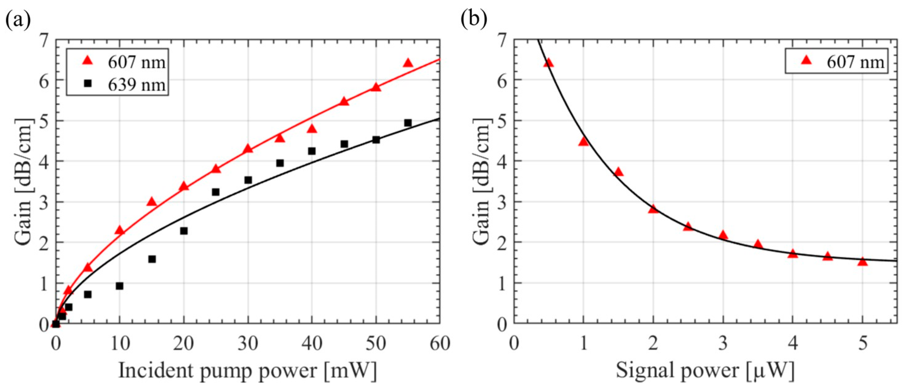
3.4. Small-Signal Amplification Measurements

The strongest amplification was achieved when both signal and pump beams had TM (σ) polarization, which correlates with the lower losses for this polarization. In Figure 6a, the small-signal gain is plotted as a function of the pump power. As expected for small-signal gain measurements, the internal gain increases with the pump power up to 6.5 dB/cm and 5 dB/cm for the 607 nm and 639 nm signal wavelengths, respectively. The maximum achieved gain was limited by the available pump power, but the onset of gain saturation is already visible in Figure 6a. The gain dependence on the signal beam power at a fixed pump power of 55 mW is shown in Figure 6b. As expected, the gain increases with decreasing signal power. For comparison, in proton-implanted Nd3+:YAG channel waveguides, a 24 dB/cm gain was achieved, and in C5+-implanted Er3+:YAG waveguides, a 4 dB/cm gain was achieved [5]. In several Nd3+-doped ion-implanted waveguides, even laser operation in the infrared range was achieved [5]. However, as far as we know, the amplification of visible light in a waveguide induced by ion implantation has not been demonstrated until now. Overall, the measured gain in our ion-implanted Pr:YLF ridge waveguides exceeds the measured loss by far, which is promising for generating laser radiation in these waveguides using suitable resonator geometry, e.g., with mirrors deposited directly onto the waveguide’s end facets.

4. Conclusions

Ridge waveguides with propagation losses as low as 0.4 dB/cm have been fabricated in Pr3+-doped YLF substrates using carbon ion (C3+) implantation with doses in the range of 2 × 10¹⁴–6 × 10¹⁵ ions/cm2 and precision diamond blade dicing. These low loss values are comparable to those of Pr:YLF waveguides produced by other methods such as fs laser inscription [14,15,16]. However, the ridge geometry realized here allows for both a stronger optical mode confinement in the lateral direction and a higher overlap of pump and laser wavelengths. During spectroscopic investigations, ion implantation did not have a negative influence on the fluorescence spectra nor on the lifetime of upper levels. Small-signal amplification in ridge waveguides of 6.5 dB/cm at 607 nm and 5 dB/cm at 639 nm wavelength was achieved, i.e., values that are significantly higher than the measured propagation losses. Thus, the obtained results are promising for the realization of efficient low-threshold waveguide lasers operating in the visible spectral range. Our future work will be focused on further reductions in propagation losses by optimizing the cutting parameters and on the realization of ion-implanted Pr:YLF ridge waveguide lasers pumped by high-power blue InGaN laser diodes. Using ion-implanted Pr:YLF ridge waveguides, visible lasers at various wavelengths (i.e., green, orange, and red) with high power and high beam quality could be integrated into a single crystal, which is of high significance for applications in display technology, communication, metrology, biology, and medicine.

Author Contributions

Conceptualization, D.K., K.H. and C.K.; methodology, D.K., K.H. and C.K.; software, S.S. and O.A.; validation, D.K., K.H., S.S. and C.K.; formal analysis, O.A., I.B. and S.S.; investigation, I.B., H.T., O.A., K.H. and S.S.; resources, D.K.; data curation, I.B., O.A., S.S., K.H. and R.M.; writing—original draft preparation, O.A.; writing—review and editing, K.H., S.S., C.K., H.T. and D.K.; visualization, O.A.; supervision, D.K.; project administration, D.K.; funding acquisition, D.K. All authors have read and agreed to the published version of the manuscript.

Funding

This research received no external funding.

Institutional Review Board Statement

Not applicable.

Informed Consent Statement

Not applicable.

Data Availability Statement

The data underlying the results presented in this paper are not publicly available at this time but may be obtained from the authors upon reasonable request.

Conflicts of Interest

The authors declare no conflicts of interest.

References

  1. Li, L.; Kong, W.; Chen, F. Femtosecond laser-inscribed optical waveguides in dielectric crystals: A concise review and recent advances. Adv. Photonics 2002, 4, 024002. [Google Scholar] [CrossRef]
  2. Gow, P.C.; Bannerman, R.H.S.; Mennea, P.L.; Holmes, C.; Gates, J.C.; Smith, P.G.R. Direct UV written integrated planar waveguides using a 213 nm laser. Opt. Express 2019, 27, 29133–29138. [Google Scholar] [CrossRef] [PubMed]
  3. Dong, N.N.; Chen, F.; Jaque, D. Carbon ion implanted Nd:MgO:LiNbO3 optical channel waveguides: An intermediate step between light and heavy ion implanted waveguides. Opt. Express 2010, 18, 5951–5956. [Google Scholar] [CrossRef] [PubMed]
  4. Chen, F.; Wang, X.L.; Wang, K.M. Development of ion-implanted optical waveguides in optical materials: A review. Opt. Mater. 2007, 29, 1523–1542. [Google Scholar]
  5. Chen, F.; Amekura, H.; Jia, Y. Ion Irradiation of Dielectrics for Photonic Applications; Springer Series in Optical Sciences; Springer: Berlin/Heidelberg, Germany, 2020; Volume 231. [Google Scholar]
  6. Bányász, I.; Szilágyi, E.; Rajta, I.; Nagy, G.U.L.; Pelli, S.; Conti, G.N.; Berneschi, S.; Havránek, V.; Vosecek, V.; Nagy, N.; et al. Fabrication of low loss channel waveguide in tungsten-tellurite glass by 11 MeV carbon ion microbeam for telecom C band. Opt. Mater. X 2019, 4, 100035. [Google Scholar] [CrossRef]
  7. Hukriede, J.; Kip, D.; Krätzig, E. Permanent narrow-band reflection holograms for infrared light recorded in LiNbO3:Ti:Cu channel waveguides. Appl. Phys. B 2001, 72, 749–753. [Google Scholar]
  8. Suntsov, S.; Rüter, C.E.; Brüske, D.; Kip, D. Watt-level 775 nm SHG with 70% conversion efficiency and 97% pump depletion in annealed/reverse proton exchanged diced PPLN ridge waveguides. Opt. Express 2021, 29, 11386–11393. [Google Scholar]
  9. Kränkel, C.; Marzahl, D.T.; Moglia, F.; Huber, G.; Metz, P.W. Out of the blue: Semiconductor laser pumped visible rare-earth doped lasers. Laser Photon. Rev. 2016, 10, 548–568. [Google Scholar]
  10. Tanaka, H.; Kalusniak, S.; Badtke, M.; Demesh, M.; Kuleshov, N.V.; Kannari, F.; Kränkel, C. Visible solid-state lasers based on Pr3+ and Tb3+. Prog. Quant. Electron. 2022, 84, 100411. [Google Scholar] [CrossRef]
  11. Richter, A.; Heumann, E.; Osiac, E.; Huber, G.; Seelert, W.; Diening, A. Diode pumping of a continuous-wave Pr3+ doped LiYF4 laser. Opt. Lett. 2004, 29, 2638. [Google Scholar] [CrossRef]
  12. Gün, T.; Metz, P.; Huber, G. Power scaling of laser diode pumped Pr3+:LiYF4 cw lasers: Efficient laser operation. Opt. Lett. 2011, 36, 1002–1004. [Google Scholar] [CrossRef] [PubMed]
  13. Calmano, T.; Siebenmorgen, J.; Reichert, F.; Fechner, M.; Paschke, A.G.; Hansen, N.O.; Petermann, K.; Huber, G. Crystalline Pr:SrAl12O19 waveguide laser in the visible spectral region. Opt. Lett. 2011, 36, 4620–4622. [Google Scholar] [CrossRef] [PubMed]
  14. Müller, S.; Calmano, T.; Metz, P.; Hansen, N.O.; Kränkel, C.; Huber, G. Femtosecond-laser-written diode-pumped Pr:LiYF4 waveguide laser. Opt. Lett. 2012, 37, 5223. [Google Scholar] [CrossRef]
  15. Baillard, A.; Loiko, P.; Romero, C.; Arroyo, V.; Vázquez de Aldana, J.R.; Fromager, M.; Braud, A.; Camy, P.; Mateos, X. Orange surface waveguide laser in Pr:LiYF4 produced by femtosecond laser writing. Opt. Lett. 2023, 48, 6212–6215. [Google Scholar] [CrossRef] [PubMed]
  16. Ren, Y.; Cui, Z.; Sun, L.; Wang, C.; Liu, H.; Cai, Y. Laser emission from low-loss cladding waveguides in Pr:YLF by femtosecond laser helical inscription. Chin. Opt. Lett. 2022, 22, 122201. [Google Scholar] [CrossRef]
  17. Baiocco, D.; Lopez-Quintas, I.; Vázquez de Aldana, J.R.; Tonelli, M.; Tredicucci, A. Comparative performance analysis of femtosecond-laser-written diode-pumped Pr:LiLuF4 visible waveguide lasers. Photonics 2023, 10, 377. [Google Scholar] [CrossRef]
  18. Bolaños, W.; Brasse, G.; Starecki, F.; Braud, A.; Doualan, J.; Moncorgé, R.; Camy, P. Green, orange, and red Pr3+:YLiF4 epitaxial waveguide lasers. Opt. Lett. 2014, 39, 4450–4453. [Google Scholar] [CrossRef]
  19. Calmano, T.; Müller, S. Crystalline waveguide lasers in the visible and near-infrared spectral range. IEEE J. Quantum Electron. 2015, 21, 401–4130. [Google Scholar] [CrossRef]
  20. Calmano, T.; Paschke, A.G.; Müller, S.; Kränkel, C.; Huber, G. Curved Yb:YAG waveguide lasers, fabricated by femtosecond laser inscription. Opt. Express 2013, 21, 25501–25508. [Google Scholar] [CrossRef]
  21. Wang, M.; Wu, R.; Lin, J.; Zhang, J.; Fang, Z.; Chai, Z.; Cheng, Y. Chemo-mechanical polish lithography: A pathway to low loss large-scale photonic integration on lithium niobate on insulator. Quantum Eng. 2019, 1, e9. [Google Scholar] [CrossRef]
  22. Zhao, J.H.; Fan, L.; Li, B.Y.; Zang, W.Z.; Liu, A.J.; Mao, J.H.; Yue, Y.; Li, S.; Yao, Y.C.; Yue, Q.Y. Planar and ridged waveguide preparation on erbium pre-implanted fused silica by multi-energy helium ion implantation and femtosecond laser ablation. Appl. Opt. 2024, 63, 5018–5022. [Google Scholar] [CrossRef]
  23. Zhao, J.H.; Liu, X.H.; Huang, Q.; Liu, P.; Wang, X.L. Lithium niobate ridge waveguides fabricated by ion implantation followed by ion beam etching. J. Light. Technol. 2010, 28, 1913–1916. [Google Scholar] [CrossRef]
  24. Ziegler, J.F. Srim-2003. Nucl. Instr. Meth. Phys. Res. B 2004, 219/220, 1027–1036. [Google Scholar] [CrossRef]
  25. Fallahkhair, A.B.; Li, K.S.; Murphy, T.E. Vector finite difference modesolver for anisotropic dielectric waveguides. J. Light. Technol. 2008, 26, 1423–1431. [Google Scholar] [CrossRef]
  26. Barnes, N.P.; Gettemy, D.J. Temperature variation of the refractive index of lithium fluoride. J. Opt. Soc. Am. 1980, 70, 1244–1247. [Google Scholar] [CrossRef]
  27. Geng, X.; Li, L.; Qian, C.; Luo, S. A full spectroscopic study of Pr:YLF crystals used in lasers. Spectroscopy 2020, 35, 39–45. [Google Scholar]
  28. Esterowitz, L.; Bartoli, F.J.; Allen, R.E.; Wortman, D.E.; Morrison, C.A.; Leavitt, R.P. Energy levels and line intensities of Pr3+ LiYF4. Phys. Rev. B 1979, 19, 6442–6455. [Google Scholar] [CrossRef]
Figure 1. Schematic of experimental setup for fluorescence measurements. E-O: electro-optic modulator; V: waveform generator; λ/2: half-wave plate; P: polarizer; L1, L2, L3: lenses; F: long-pass filter; BS: beam splitter; PM: power meter; M: monochromator; PMT: photomultiplier tube; OS: oscilloscope.
Applsci 15 04956 g001
Figure 2. A schematic of the experimental setup for small-signal gain measurements. BS: beam splitter; λ/2: half-wave plate; DM: dichroic mirror; M: mirror; L1, L2: lenses; F: long-pass filter; P: polarizer; PM: power meter.
Applsci 15 04956 g002
Figure 3. (a,c) Mode spectrum (intensity vs. refractive index) of waveguide Pr:YLF-3 for TM (no) and TE (ne) polarization, measured at 532 nm wavelength. Respective bulk indices are indicated by red dashed lines. (b,d) Reconstructed refractive indices of planar waveguides (blue) and intensities of fundamental modes at 532 nm wavelength (red). Effective indices of first six modes for each polarization are shown with black horizontal lines.
Applsci 15 04956 g003
Figure 4. A three-dimensional scanning electron microscope (SEM) image of two ridge waveguides in Pr:YLF-3. Left inset: details of the end facet of a 22 µm wide waveguide. Right inset: the output mode intensity profile of this ridge waveguide at a 632.8 nm wavelength.
Applsci 15 04956 g004
Figure 5. Fluorescence spectra of bulk and ridge waveguide for (a) π polarization and (b) σ polarization, recorded from sample Pr:YLF-3 under excitation at wavelength of 444 nm.
Applsci 15 04956 g005
Figure 6. (a) Small-signal internal gain vs. pump power for wavelengths of 607 nm and 639 nm in a 22 µm wide ridge waveguide at fixed signal powers of 0.5 µW (607 nm) and 0.7 µW (639 nm), respectively. (b) Small-signal gain as a function of the signal power at a fixed incident pump power of 55 mW.
Applsci 15 04956 g006
Disclaimer/Publisher’s Note: The statements, opinions and data contained in all publications are solely those of the individual author(s) and contributor(s) and not of MDPI and/or the editor(s). MDPI and/or the editor(s) disclaim responsibility for any injury to people or property resulting from any ideas, methods, instructions or products referred to in the content.

