Article

Research on Relative Position and Attitude Measurement of Space Maglev Vibration Isolation Control System

School of Automation, Nanjing University of Science and Technology, Nanjing 210094, China
*
Authors to whom correspondence should be addressed.
Appl. Sci. 2025, 15(9), 4912; https://doi.org/10.3390/app15094912
Submission received: 17 March 2025 / Revised: 17 April 2025 / Accepted: 24 April 2025 / Published: 28 April 2025

Abstract

:
The working accuracy of space optical payloads, sensitive components, greatly depends on the pointing accuracy and stability of the platform. This article establishes a mathematical model for relative position and attitude measurement based on PSD and eddy current and analyzes the failure modes under the measurement models. Through model derivation, it can be concluded that the position and attitude measurement system has high redundancy; in the event of sensor failure in the horizontal or vertical direction, relative position and attitude measurement and resolution can still be completed, which solves the relative measurement problem of position and attitude measurement of the space Maglev vibration isolation control system, providing high-precision closed-loop control for the control system to achieve high-precision pointing and stability. In response to the requirements of high-precision non-contact displacement and attitude measurement, eddy current sensors were selected, and a sensor circuit box was designed. The testing and calibration system adopts an eight-bar Maglev layout, and the actuator has unidirectional dual-mode output. The actuator adopts a double closed magnetic circuit structure, and the coil adopts a winding single-coil structure. The system includes a multi-degree-of-freedom high-precision coil spatial pose automatic positioning platform, a strong magnetic structure, strong uniform magnetic field magnetization, an integrated assembly testing platform, etc. According to the test data, the driver has strong linearity in both low- and high-current ranges. The relative output error in the low-current range does not exceed 0.1 mA, and the relative output error in the high-current range does not exceed 2 mA. After fitting and calibration, it can meet the design requirements. Within redundant designing, fault mode analyzing, and system testing, the relative measurement system can ensure the working accuracy of the optical payload of the spacecraft, which reaches the advanced level in the field.

1. Introduction

The working accuracy of space optical payloads, sensitive components carried on space aircraft, greatly depends on the pointing accuracy and stability of the platform. Non-contact Maglev technology is proposed, in which the vibration and interference of the platform module are not transmitted to the payload module, to achieve the effect of vibration isolation [1].
The precision of the measurement model was determined by the layout and quantity of position-sensitive detectors (PSDs) [2] for high-precision non-contact displacement measurement, which can achieve superior isolation performance [3]. The available sensors mainly include laser displacement sensors, capacitive displacement sensors, and eddy current displacement sensors. Due to the small range of capacitive displacement sensors, laser displacement sensors and eddy current sensors are mainly considered [4,5,6,7]. In response to the requirements of high-precision non-contact displacement and attitude measurement, eddy current sensors were selected, and a sensor circuit box was designed. Challenges such as sensor calibration errors, nonlinear system dynamics, and environmental disturbances can compromise measurement accuracy.
This article establishes a mathematical model for relative position and attitude measurement based on PSDs and eddy current [8,9,10] and analyzes the failure modes under the measurement models. It analyzes one of the vertical sensor failures and one of the horizontal sensor failures. Through model derivation, it can be concluded that the position and attitude measurement system has high redundancy; in the event of sensor failure in the horizontal or vertical direction, the relative position and attitude measurement and the resolution can still be determined [11,12].
The testing and calibration system adopts an eight-bar Maglev layout, and the actuator has unidirectional dual-mode output. The actuator adopts a double closed magnetic circuit structure, and the coil adopts a winding single-coil structure. The system includes a multi-degree-of-freedom high-precision coil spatial pose automatic positioning platform, a strong magnetic structure, strong uniform magnetic field magnetization, an integrated assembly testing platform, etc. [13,14]. The testing and calibration system mainly includes a multi-degree-of-freedom high-precision coil spatial pose automatic positioning platform, a strong magnetic structure, strong uniform magnetic field magnetization, an integrated assembly testing platform, a multi-channel ultra-high-precision real-time driving current measurement system, a multi-directional large-span ultra-high-precision force performance measurement system, a testing control and data analysis processing unit, etc. [15,16].
This study highlights the importance of relative measurement techniques, failure modes, and advanced calibration methods in achieving optimal system performance. According to the test data, the driver has strong linearity in both low- and high-current ranges. The relative output error in the low-current range does not exceed 0.1 mA, and the relative output error in the high-current range does not exceed 2 mA. After fitting and calibration, it meets the design requirements.

2. Relative Position and Attitude Measurement of Maglev Vibration Isolation System

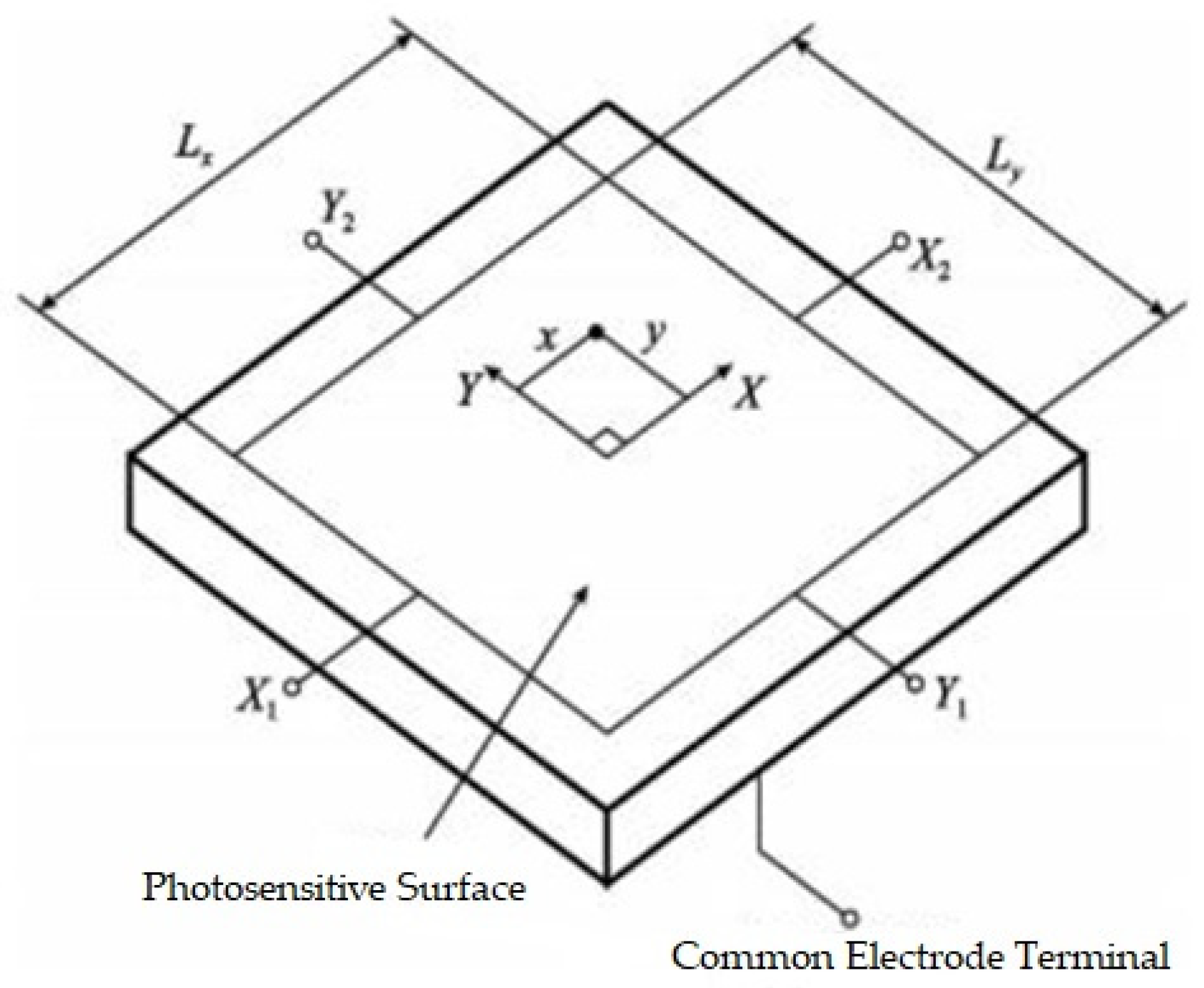
2.1. Measurement Scheme Based on Two-Dimensional PSD

PSDs work on the basis of the transverse photoelectric effect and generally adopt a P-N-N+ structure. The substrate is an N-type high-resistance layer, and the back of the substrate is an N+ layer connected to a common electrode terminal to provide appropriate reverse voltage. The surface P layer is a photosensitive surface to form a planar distributed resistance. Four electrodes are drawn out for collecting photocurrent at the geometric center positions on two pairs of opposite sides of the photosensitive surface. A two-dimensional PSD is shown in Figure 1.
When a light beam is irradiated onto a photosensitive surface to form a spot, a photo-generated charge proportional to the incident energy is generated at the center of the spot. At the same time, the reverse voltage applied to the common electrode terminal causes the formation of a photocurrent I0, which diffuses in the form of surface current on the photosensitive surface and is led out by four lead-out electrodes, X1, X2, Y1, and Y2. The currents are I1, I2, I3, and I4, and the magnitude of each current is inversely proportional to the impedance between the center position of the light spot and the corresponding output electrode. If the planar resistance distribution of the P layer is uniform, the magnitude of the photocurrent output by each electrode is inversely proportional to the position from the center position of the light spot to each pole. Taking the centroid position of the photosensitive surface as the coordinate origin of the two-dimensional X-Y coordinate system, the coordinate position of the light spot center on the PSD surface in the two-dimensional X-Y coordinate system can be calculated based on the relationship between each current.
When using other displacement sensors, two displacement sensors can be used to equivalently replace a two-dimensional PSD, and the scheme and layout can refer to the two-dimensional PSD.

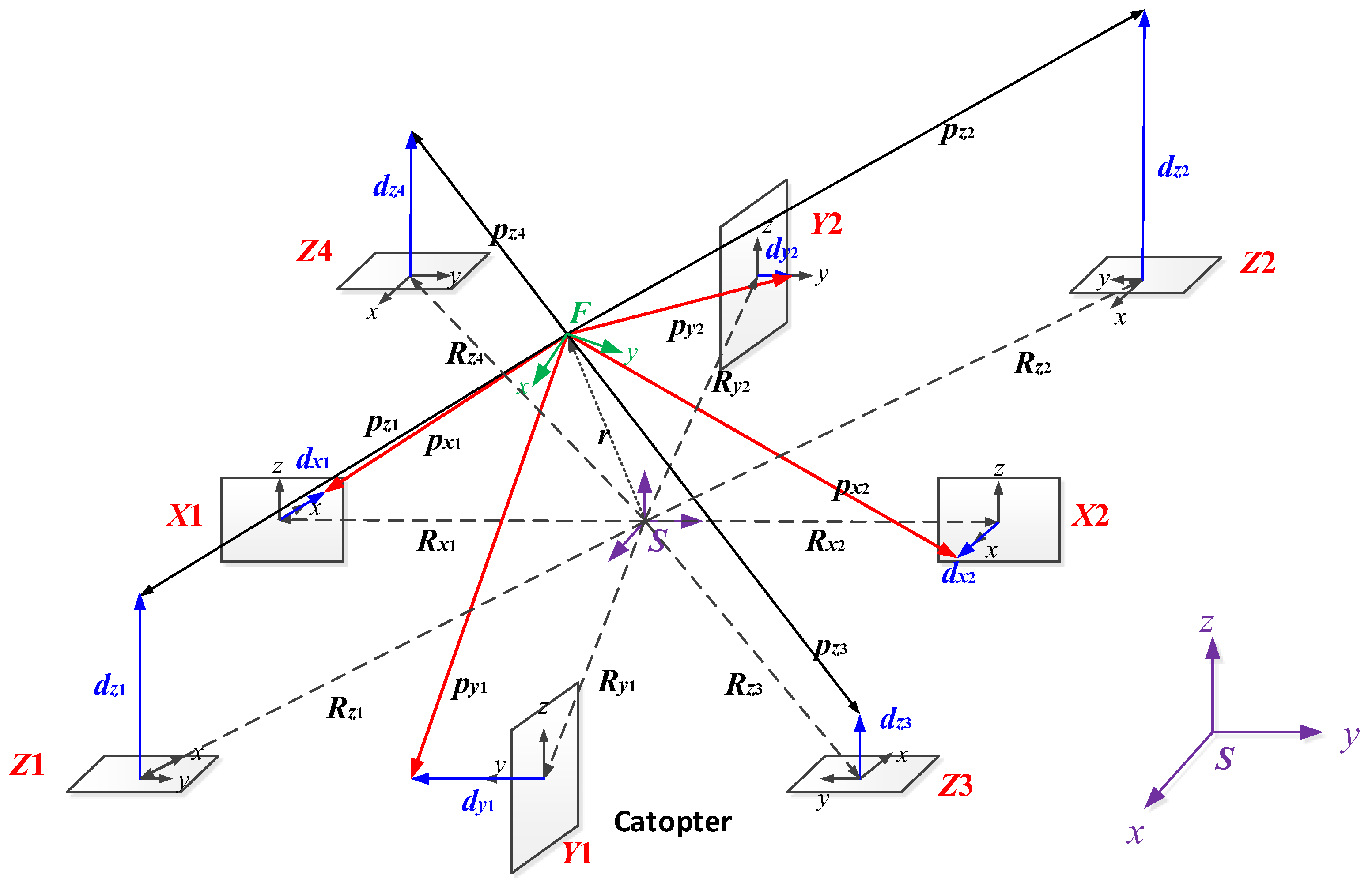
2.2. Relative Position and Attitude Measurement Model of Maglev Vibration Isolation System

The six-DOF relative position and attitude measurement system is used to measure the three-axis relative attitude and three-axis relative centroid position of the support module relative to the payload module. At present, there are mainly 4-bar and 8-bar sensor configuration schemes, as shown in Figure 2.
In theory, at least three two-dimensional PSDs are required to achieve the calculation of three degrees of freedom displacement and angle. In order to achieve hardware redundancy and improve calculation accuracy, the system uses four two-dimensional PSDs, with the photosensitive surface fixed on the base side plate and four laser sources fixed on the floating platform side plate. When the base is disturbed, the position of the PSD photosensitive surface changes accordingly, and the position of the light spot irradiated by the laser source on the photosensitive surface also changes. By collecting and processing the output current changes of the photosensitive surface pins, the displacement changes of the light spot on the photosensitive surface can be obtained.
Based on the three-dimensional position measurement model, the relationship between the relative position and angle changes between the floating platform and the base is established, and the displacement changes of the light spot on the photosensitive surface are determined.
The 4-bar layout requires the configuration of bidirectional position sensors, such as two-dimensional PSD. The 8-bar layout requires the configuration of traditional unidirectional position measurement sensors, such as laser or eddy current. Compared to the others, the layout of the 8-bar position sensor has a higher system redundancy, allowing for the arbitrary failure of one out of four sets in the longitudinal and transverse directions. When there is only a one-way failure in the actuator, it does not affect the payload module’s motion of 6 DOF (degrees of freedom) [1].

2.3. Relative Position and Attitude Measurement Based on PSD

In order to analyze the relative motion between the floating platform and the base, a base coordinate system S is established, with the horizontal axis parallel to the light rays of the four sets of light sources on the floating platform. A floating platform coordinate system F is established, with its coordinate axis origin perpendicular to the photosensitive surfaces of position sensors 1, 2, 3, and 4 and passing through their centroids. Sensor coordinate systems are established for each PSD photosensitive surface. The Z-axis direction of the four sensor coordinate systems is consistent with the Z-axis direction of the platform coordinate system [2].

2.4. Relative Position and Attitude Measurement Based on Eddy Current

A three-dimensional position measurement model is established, as shown in Figure 3. Sensors X1 and X2 can measure relative positional changes along the x-axis and angular changes around the x-axis; sensors Y1 and Y2 can measure relative positional changes along the y-axis and angular changes around the y-axis; and sensors Z1, Z2, Z3, and Z4 can measure relative positional changes along the z-axis and angular changes around the z-axis.
In order to analyze the relative motion between the floating platform and the base, the base coordinate system S and the floating platform coordinate system F are established. The XOZ plane is made coplanar with the reflective surfaces of sensors Y1 and Y2, the YOZ plane is made coplanar with the reflective surfaces of sensors X1 and X2, and the XOY plane is made coplanar with the reflective surfaces of sensors Z1, Z2, Z3, and Z4.
The sensor coordinate systems CX1, CX2, CY1, CY2, CZ1, CZ2, CZ3, and CZ4, respectively, are established at the centroid of the reflection surface of each eddy current sensor, and the z-axis direction of sensors X1, X2, Y1, Y2, Z1, Z2, Z3, and Z4 is the same as the z-axis direction of the platform coordinate system.
The transformation matrix between the base coordinate system and the floating platform coordinate system is defined as C, and the Euler angle of the coordinate transformation are assumed as θx, θy, θz. According to Euler’s equation, there is:
C = R θ x R θ y R θ z    = cos θ y cos θ z cos θ y sin θ z sin θ y sin θ x sin θ y cos θ z + cos θ x sin θ z sin θ x sin θ y sin θ z + cos θ x cos θ z sin θ x cos θ y cos θ x sin θ y cos θ z + sin θ x sin θ z cos θ x sin θ y sin θ z + sin θ x cos θ z cos θ x cos θ y
R θ x = 1 0 0 0 cos θ x sin θ x 0 sin θ x cos θ x , R θ y = cos θ y 0 sin θ y 0 1 0 sin θ y 0 cos θ y , R θ z = cos θ z sin θ z 0 sin θ z cos θ z 0 0 0 1
Considering the small-angle rotation, the transformation matrix C can be simplified to:
C = 1 θ z θ y θ z 1 θ x θ y θ x 1
The transformation matrix between the reflective surface coordinate system and the base coordinate system is defined as Cp. According to the installation position of the eddy current sensor, the following is obtained:
C p X 1 = 1 0 0 0 1 0 0 0 1 , C p X 2 = 1 0 0 0 1 0 0 0 1 , C p Y 1 = 1 0 0 0 1 0 0 0 1 , C p Y 2 = 1 0 0 0 1 0 0 0 1 C p Z 1 = 1 0 0 0 1 0 0 0 1 , C p Z 2 = 1 0 0 0 1 0 0 0 1 , C p Z 3 = 1 0 0 0 1 0 0 0 1 , C p Z 4 = 1 0 0 0 1 0 0 0 1
Assuming that in the initial state, the floating platform coordinate system coincides with the base coordinate system.
(1) In the base coordinate system, the position vector of the base deviating from the floating platform after disturbance is defined as r = [x y z]T.
(2) The position vector from the origin of the base coordinate to the center of the reflection surface of the eddy current sensor is R.
(3) In the floating platform coordinate system, the position vector from the floating platform coordinate origin to the reflection surface of the eddy current sensor is defined as p.
(4) In the sensor coordinate system, the position vector from the origin of the reflective surface coordinate system to the measurement point is defined as d.
In the floating platform coordinate system, according to the geometric position relationship of the spatial vector, the following can be obtained:
p F = C F / S ( C S / C p i d C p i + R S r S )
The distance from the origin of the base coordinate to the origin of the reflection surface coordinate of the eddy current sensor can be written as:
R = 0 0 R y 1 R y 2 R x 1 R x 2 0 0 0 0 0 0 R z 1 x R z 2 x R z 3 x R z 4 x R z 1 y R z 2 y R z 3 y R z 4 y 0 0 0 0
In the floating platform coordinate system, the distance from the origin of the floating platform coordinate to the irradiation point of the eddy current sensor can be expressed as:
p = 0 0 p y 1 x p y 2 x p x 1 y p x 2 y 0 0 p x 1 z p x 2 z p y 1 z p y 2 z p z 1 x p z 2 x p z 3 x p z 4 x p z 1 y p z 2 y p z 3 y p z 4 y 0 0 0 0
The position matrix in the coordinate system of the eddy current sensor is:
d = d x 1 d x 2 0 0 0 0 d y 1 d y 2 0 0 0 0 0 0 0 0 0 0 0 0 d z 1 d z 2 d z 3 d z 4
It can be concluded that:
0 p x 1 y p x 1 z = C d x 1 x R x 1 y z , 0 p x 2 y p x 2 z = C d x 2 x R x 2 y z , p y 1 x 0 p y 1 z = C R y 1 x d y 1 y z , p y 2 x 0 p y 2 z = C R y 2 x d y 2 y z , p z 1 x p z 1 y 0 = C R z 1 x x R z 1 y y d z 1 z , p z 2 x p z 2 y 0 = C R z 2 x x R z 2 y y d z 2 z , p z 3 x p z 3 y 0 = C R z 3 x x R z 3 y y d z 3 z , p z 4 x p z 4 y 0 = C R z 4 x x R z 4 y y d z 4 z

3. Failure Mode Analysis

3.1. Fully Redundant

The fully redundant state means no sensor failure. Substituting Equation (4) into Equation (9) produces:
x + y θ z z θ y θ z R x 1 = d x 1 x y θ z + z θ y + θ z R x 2 = d x 2 y x θ z + z θ x + θ z R y 1 = d y 1 y + x θ z z θ x + θ z R y 2 = d y 2 z x θ y + y θ x + R z 1 x θ y + R z 1 y θ x = d z 1 z x θ y + y θ x R z 2 x θ y R z 2 y θ x = d z 2 z x θ y + y θ x + R z 3 x θ y R z 3 y θ x = d z 3 z x θ y + y θ x R z 4 x θ y + R z 4 y θ x = d z 4
After transforming Equation (10), the relative position between the base and the floating platform is represented as:
x y z = 1 θ z θ y θ z 1 θ x θ y θ x 1 1 m 1 m 2 m 3
where:
m 1 = 1 2 d x 2 d x 1 θ z R x 1 + R x 2 m 2 = 1 2 d y 2 d y 1 + θ z R y 1 R y 2 m 3 = 1 4 d z 1 + d z 2 + d z 3 + d z 4 + θ x R z 2 y R z 1 y + R z 3 y R z 4 y + θ y R z 2 x R z 1 x + R z 4 x R z 3 x
1 θ z θ y θ z 1 θ x θ y θ x 1 = 1 + θ x 2 + θ y 2 + θ z 2 0
Based on the small-angle assumption for simplification, the formula for solving the relative position between the base and the floating platform in three degrees of freedom can be represented as:
x = m 1 + m 2 θ z m 3 θ y y = m 2 m 1 θ z + m 3 θ x z = m 3 + m 1 θ y m 2 θ x
Similarly, the relative three-degree-of-freedom angle solution formula between the base and the floating platform is obtained:
θ x = ( R z 3 x + R z 4 x ) ( d z 1 d z 2 ) ( R z 1 x + R z 2 x ) ( d z 3 d z 4 ) ( R z 1 x + R z 2 x ) ( R z 3 y + R z 4 y ) + ( R z 3 x + R z 4 x ) ( R z 1 y + R z 2 y ) θ y = ( R z 3 y + R z 4 y ) ( d z 1 d z 2 ) + ( R z 1 y + R z 2 y ) ( d z 3 d z 4 ) ( R z 1 x + R z 2 x ) ( R z 3 y + R z 4 y ) + ( R z 3 x + R z 4 x ) ( R z 1 y + R z 2 y ) θ z = 1 2 d x 1 + d x 2 R x 2 R x 1 + d y 1 + d y 2 R y 1 + R y 2

3.2. Vertical Failure 1 Set

When any one of the vertical sensors Z1, Z2, Z3, or Z4 fails, it means the measurement signal dz1 is invalid. Assuming that eddy current sensor Z1 fails, Equation (10) is rewritten as:
x + y θ z z θ y θ z R x 1 = d x 1 x y θ z + z θ y + θ z R x 2 = d x 2 y x θ z + z θ x + θ z R y 1 = d y 1 y + x θ z z θ x + θ z R y 2 = d y 2 z x θ y + y θ x R z 2 x θ y R z 2 y θ x = d z 2 z x θ y + y θ x + R z 3 x θ y R z 3 y θ x = d z 3 z x θ y + y θ x R z 4 x θ y + R z 4 y θ x = d z 4
Similarly, the relative position between the base and the floating platform can be expressed as:
x y z = 1 θ z θ y θ z 1 θ x θ y θ x 1 1 m 1 m 2 m 3
where:
m 1 = 1 2 d x 2 d x 1 θ z R x 1 + R x 2 m 2 = 1 2 d y 2 d y 1 + θ z R y 1 R y 2 m 3 = 1 3 d z 2 + d z 3 + d z 4 + θ x R z 2 y + R z 3 y R z 4 y + θ y R z 2 x + R z 4 x R z 3 x
1 θ z θ y θ z 1 θ x θ y θ x 1 = 1 + θ x 2 + θ y 2 + θ z 2 0
The formula for solving the relative position between the base and the floating platform in three degrees of freedom is as follows:
x = m 1 + m 2 θ z m 3 θ y y = m 2 m 1 θ z + m 3 θ x z = m 3 + m 1 θ y m 2 θ x
The formula for solving the relative angle between the base and the floating platform in three degrees of freedom is as follows:
θ x = ( R z 3 x + R z 4 x ) ( d z 3 d z 2 ) ( R z 2 x + R z 3 x ) ( d z 3 d z 4 ) ( R z 2 x + R z 3 x ) ( R z 3 y + R z 4 y ) + ( R z 3 x + R z 4 x ) ( R z 2 y R z 3 y ) θ y = ( R z 3 y + R z 4 y ) ( d z 3 d z 2 ) + ( R z 2 y R z 3 y ) ( d z 3 d z 4 ) ( R z 2 x + R z 3 x ) ( R z 3 y + R z 4 y ) + ( R z 3 x + R z 4 x ) ( R z 2 y R z 3 y ) θ z = 1 2 d x 1 + d x 2 R x 2 R x 1 + d y 1 + d y 2 R y 1 + R y 2
From the above derivation, it can be seen that the position and attitude measurement system has high redundancy and can still complete relative position and attitude measurement and resolution, even in the event of the failure of one vertical sensor.

3.3. Horizontal Failure 1 Set

When any one of the horizontal sensors X1, X2, Y1, or Y2 fails, it means the measurement signal dx1 is invalid. Assuming that eddy current sensor Z1 fails, Equation (10) is rewritten as:
x y θ z + z θ y + θ z R x 2 = d x 2 y x θ z + z θ x + θ z R y 1 = d y 1 y + x θ z z θ x + θ z R y 2 = d y 2 z x θ y + y θ x + R z 1 x θ y + R z 1 y θ x = d z 1 z x θ y + y θ x R z 2 x θ y R z 2 y θ x = d z 2 z x θ y + y θ x + R z 3 x θ y R z 3 y θ x = d z 3 z x θ y + y θ x R z 4 x θ y + R z 4 y θ x = d z 4
The relative position between the base and the floating platform can be expressed as:
x y z = 1 θ z θ y θ z 1 θ x θ y θ x 1 1 m 1 m 2 m 3
where:
m 1 = d x 2 θ z R x 2 m 2 = 1 2 d y 2 d y 1 + θ z R y 1 R y 2 m 3 = 1 4 d z 1 + d z 2 + d z 3 + d z 4 + θ x R z 2 y R z 1 y + R z 3 y R z 4 y + θ y R z 2 x R z 1 x + R z 4 x R z 3 x
1 θ z θ y θ z 1 θ x θ y θ x 1 = 1 + θ x 2 + θ y 2 + θ z 2 0
The formula for solving the relative position between the base and the floating platform in three degrees of freedom is as follows:
x = m 1 + m 2 θ z m 3 θ y y = m 2 m 1 θ z + m 3 θ x z = m 3 + m 1 θ y m 2 θ x
The formula for solving the relative angle between the base and the floating platform in three degrees of freedom is as follows:
θ x = ( R z 3 x + R z 4 x ) ( d z 1 d z 2 ) ( R z 1 x + R z 2 x ) ( d z 3 d z 4 ) ( R z 1 x + R z 2 x ) ( R z 3 y + R z 4 y ) + ( R z 3 x + R z 4 x ) ( R z 1 y + R z 2 y ) θ y = ( R z 3 y + R z 4 y ) ( d z 1 d z 2 ) + ( R z 1 y + R z 2 y ) ( d z 3 d z 4 ) ( R z 1 x + R z 2 x ) ( R z 3 y + R z 4 y ) + ( R z 3 x + R z 4 x ) ( R z 1 y + R z 2 y ) θ z = d y 1 + d y 2 R y 1 + R y 2
From the above derivation, it can be seen that the position and attitude measurement system has high redundancy and can still complete relative position and attitude measurement and resolution, even in the event of a failure of one horizontal sensor.

4. Displacement Sensing and Signal Acquisition

4.1. Selection of Displacement Sensor

For high-precision non-contact displacement measurement, the available sensors mainly include laser displacement sensors, capacitive displacement sensors, and eddy current displacement sensors. Due to the small range of capacitive displacement sensors, laser displacement sensors and eddy current sensors are mainly considered.
(1)
Laser displacement sensor
At present, high-precision laser displacement sensors generally use the principle of triangulation for distance measurement. A representative laser displacement sensor is the ZSY brand, which has a resolution of up to 7.6 nm and 0.02% FS linearity in a large range. The disadvantages of laser displacement measurement are that it is mainly affected by environmental factors, and the range span of shelf products is large, which is not conducive to selection.
(2)
Eddy current displacement sensor
The principle of eddy current sensors is to accurately measure the relative position between the measured metal conductor and the probe end face through the eddy current effect. Its characteristics are good long-term reliability, high sensitivity, strong anti-interference ability, non-contact measurement, fast response speed, and being unaffected by media such as oil and water. It is more suitable for the displacement measurement of Maglev mechanisms.
At present, well-known brands of eddy current displacement sensors include KAMAN from the United States, Keyence from Japan, and ZSY from the United Kingdom. Compared to others, KAMAN from the United States has the best overall performance and range coverage.
At present, the measurement requirement for displacement sensors is a range of ±20 mm, with an accuracy better than 5 μm. Referring to the selection of KAMAN eddy current sensors, the KAMAN 12CU probe (paired with the KD-2306 adapter) can be selected, with a measurement range of 50.8 mm and an accuracy of 5 μm, meeting the measurement accuracy requirements. Considering the relatively good thermal control environment on the satellite, and considering the use of reliable sensor products, such as KAMAN sensors, the operating temperature can reach −55 °C to +105 °C.

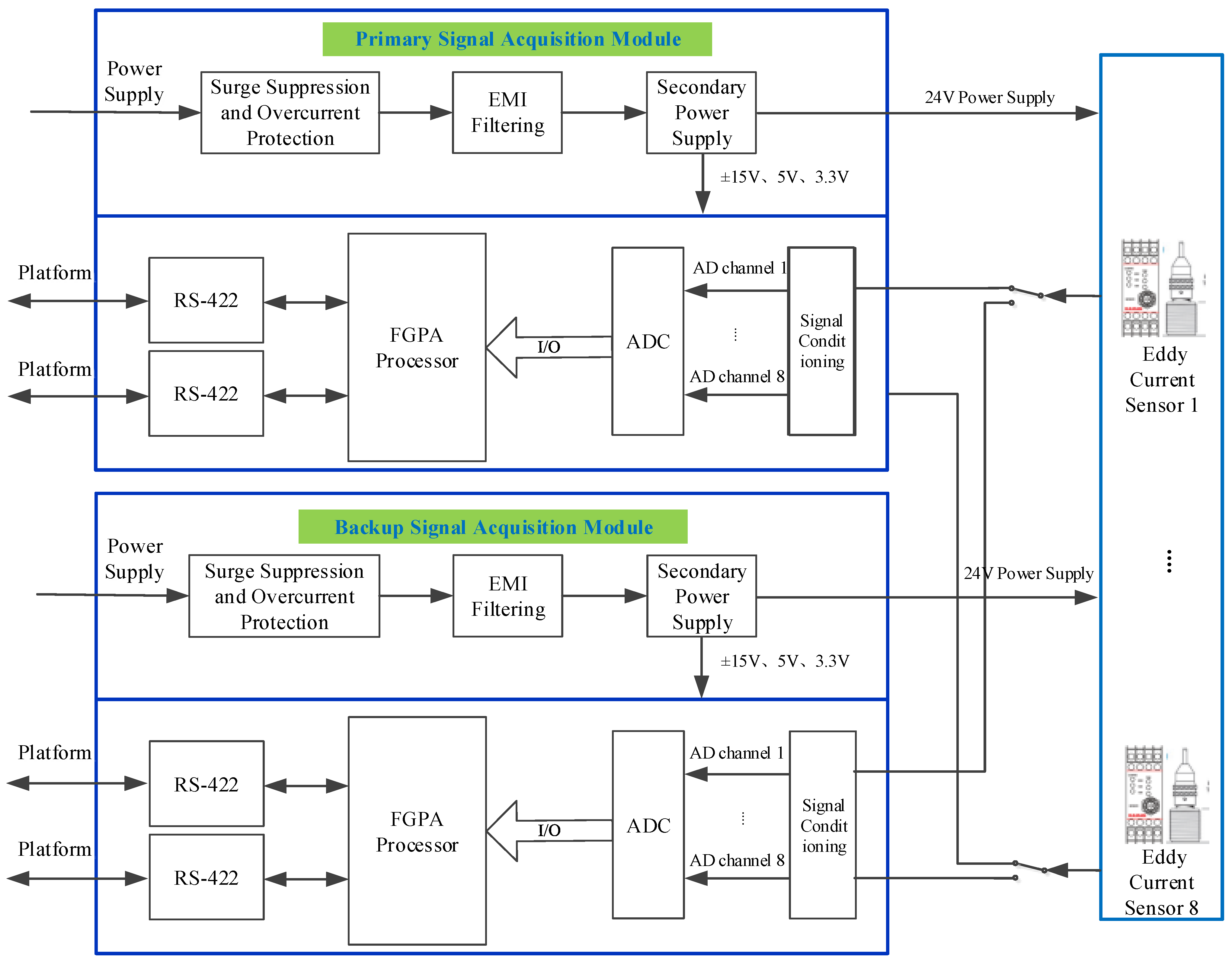
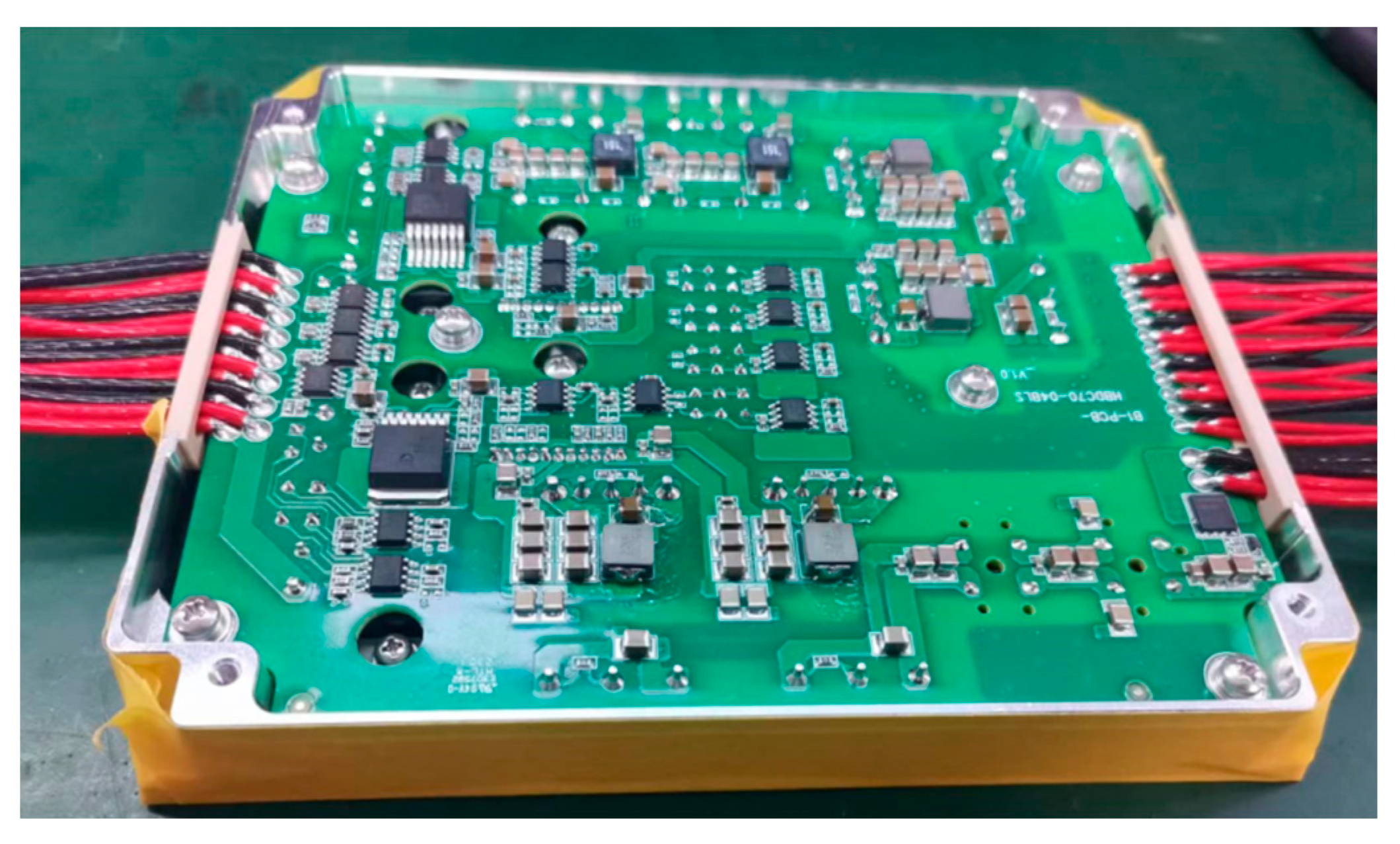
4.2. Sensor Circuit Box Design

The eddy current sensor circuit box is used to meet the power supply, signal acquisition, and transmission functions of eight sensors. The design scheme of the sensor circuit box is shown in Figure 4.
The PCB board of the circuit box includes two parts: the power supply and the functional circuit.
(1)
The power supply includes several parts, including surge suppression and overcurrent protection, EMI filtering, and a secondary power supply. It provides various voltage levels of driving power supply for the functional circuit section and also provides input power supply for eight sensors.
(2)
The functional circuit includes a processor, ADC sampling circuit, sensing signal conditioning circuit, and 422 communication. Its main function is high-precision sampling of eddy current sensor signals, and it is also responsible for data exchange with the attitude and orbit control system.

5. System Design and Testing

5.1. Maglev Vibration Isolation Control System Design

The system scheme adopts an eight-bar Maglev layout, and the actuator has unidirectional dual-mode output. The actuator adopts a double closed magnetic circuit structure, and the coil adopts a winding single-coil structure. The controller controls the output switching between high-force current and high-precision current of the power board through the enable signal, thereby achieving dual-mode output of high precision and high-force value of the actuator. The overall configuration is shown in Figure 5. The controller prototype is shown in Figure 6.

5.2. System Testing

The testing and calibration system mainly includes a multi-degree-of-freedom high-precision coil spatial pose automatic positioning platform, a strong magnetic structure, strong uniform magnetic field magnetization, an integrated assembly testing platform, a multi-channel ultra-high-precision real-time driving current measurement system, a multi-directional large-span ultra-high-precision force performance measurement system, and a testing control and data analysis processing unit. The overall configuration scheme is shown in Figure 7.
The least-squares method is applied to fit the current output curve, and the relative output error is calculated. For high-precision coils and high-force coils, the performance data for the high-precision current and high current are shown in Table 1 and Table 2.
According to the test data, the driver has strong linearity in both low- and high-current ranges. The relative output error in the low-current range does not exceed 0.1 mA, and the relative output error in the high-current range does not exceed 2 mA. After fitting and calibration, it meets the design requirements. The sensor circuit box and controller also participated in the joint debugging and testing of the platform system, and the electromagnetic interference between electronic products was verified.
The current and output electromagnetic force reached their maximum values in approximately 5 ms. Therefore, the electromagnetic actuation part meets a response output of 200 Hz [1], and the frequency response is higher than that in typical space mission requirements (e.g., <100 Hz for telescopes).

6. Conclusions

The findings of this study are summarized as follows:
By establishing a relative position and attitude measurement model based on PSDs and eddy current, as well as a six-DOF relative position and attitude measurement system, compared with four-bar and eight-bar sensor configuration schemes, we find that the layout of an eight-bar position sensor has a higher system redundancy, allowing for the arbitrary failure of one out of four sets in the longitudinal and transverse directions. When there is only a one-way failure in the actuator, it does not affect the payload module’s motion of six DOF (degrees of freedom). Meanwhile, by analyzing the failure modes under the measurement models, it can be concluded that the position and attitude measurement system has high redundancy.
Based on a self-designed testing and calibration system that adopts an eight-bar Maglev layout, the actuator has unidirectional dual-mode output. Separately, small-current (high-precision) and high-current (high-force value) conditions were tested, and the least-squares method was applied to fit the current output curve and calculate the relative output error. It can be concluded that the system has strong linearity in both low- and high-current ranges. The relative output error in the low-current range does not exceed 0.1 mA, and the relative output error in the high-current range does not exceed 2 mA, which meets the design requirements. The experimental results demonstrate that the proposed system achieves significant reductions in vibration transmission compared to traditional methods.
Although the performance of the Maglev vibration isolation control system relative measurement system was validated in the platform system, system-level tests such as sinusoidal vibration, random vibration, and impact still need to be conducted throughout the entire platform system in the future. Simultaneously, the robustness of the system must be verified under multi-axis interference on the air flotation test bench.

Author Contributions

Conceptualization, J.W.; methodology, J.W.; validation, M.Y.; formal analysis, M.Y.; investigation, M.Y.; resources, J.W.; data curation, M.Y.; writing—original draft preparation, M.Y.; writing—review and editing, J.W.; visualization, M.Y.; supervision, J.W.; project administration, M.Y. All authors have read and agreed to the published version of the manuscript.

Funding

This research received no external funding.

Institutional Review Board Statement

Not applicable.

Informed Consent Statement

Not applicable.

Data Availability Statement

The raw data supporting the conclusions of this article will be made available by the authors on request.

Conflicts of Interest

The authors declare no conflict of interest.

References

  1. Ye, M.; Wang, J. Research on Space Maglev Vibration Isolation Control System Modeling and Simulation. Appl. Sci. 2025, 15, 1648. [Google Scholar] [CrossRef]
  2. Wu, Q.; Liu, B.; Cui, N.; Zhao, S. Tracking Control of a Maglev Vibration Isolation System Based on a High-Precision Relative Position and Attitude Model. Sensors 2019, 19, 3375. [Google Scholar] [CrossRef] [PubMed]
  3. Smith, J.; Johnson, L. Advanced Vibration Control Using Magnetic Levitation. J. Precis. Eng. 2020, 45, 234–249. [Google Scholar] [CrossRef]
  4. Chen, X.; Wang, Y. Relative Measurement Techniques in Maglev Systems. Int. J. Mech. Sci. 2019, 78, 112–125. [Google Scholar] [CrossRef]
  5. Zhang, H.; Liu, R. Applications of Maglev Technology in High-Precision Industries. IEEE Trans. Ind. Electron. 2021, 68, 4567–4578. [Google Scholar]
  6. Lee, K.; Park, S. Design and Control of a Maglev-Based Vibration Isolation System with Relative Displacement Feedback. Mechatronics 2018, 52, 78–90. [Google Scholar] [CrossRef]
  7. Brown, T.; Davis, M. High-Precision Vibration Isolation Using Maglev and Optical Relative Measurement Sensors. Sens. Actuators A Phys. 2022, 335, 113–125. [Google Scholar]
  8. Jiang, D.; Shan, Y.; Wang, D.; Yang, J. Data analysis and processing for Maglev vibration test systems. In Proceedings of the 2015 12th IEEE International Conference on Electronic Measurement & Instruments (ICEMI), Qingdao, China, 16–18 July 2015. [Google Scholar] [CrossRef]
  9. Wu, Q.; Yue, H.; Liu, R.; Zhang, X.; Ding, L.; Liang, T.; Deng, Z. Measurement Model and Precision Analysis of Accelerometers for Maglev Vibration Isolation Platforms. Sensors 2015, 15, 20053–20068. [Google Scholar] [CrossRef] [PubMed] [PubMed Central]
  10. Xue, S.; He, N.; Long, Z. Electromagnetic field analysis and modeling of a relative position detection sensor for high speed maglev trains. Sensors 2012, 12, 6447–6462. [Google Scholar] [CrossRef] [PubMed] [PubMed Central]
  11. Gong, Z.; Ding, L.; Li, S.; Yue, H.; Gao, H.; Deng, Z. Payload-agnostic decoupling and hybrid vibration isolation control for a maglev platform with redundant actuation. Mech. Syst. Signal Process. 2021, 146, 106985. [Google Scholar] [CrossRef]
  12. Zhang, D.; Long, Z.; Xue, S.; Zhang, J. Optimal Design of the Absolute Positioning Sensor for a High-Speed Maglev Train and Research on Its Fault Diagnosis. Sensors 2012, 12, 10621–10638. [Google Scholar] [CrossRef] [PubMed]
  13. Zhang, H.-S.; Cao, X.-K.; Guo, B.; Wang, Q.; Fu, Y.-H. An approach of Eddy Current Sensor Calibration in State Estimation for Maglev System. In Proceedings of the 2007 International Confernece on Electrical Machines and Systems, Seoul, Republic of Korea, 8–11 October 2007. [Google Scholar]
  14. Owen, R.B.; Maggiore, M. Implementation and model verification of a magnetic levitation system. In Proceedings of the 2005, American Control Conference, 2005, Portland, OR, USA, 8–10 June 2005; Volume 2, pp. 1142–1147. [Google Scholar] [CrossRef]
  15. Southwest Jiaotong University. Vibration Test Bench for Electrodynamic-Suspension Magnetic Levitation (Maglev) Trains and Testing Method Using Same. US17540622, 21 June 2022. [Google Scholar]
  16. Zhang, H.; Wang, L.; Yang, N.; Cao, X. Study of Sensor Calibration Method for the Maglev Control System. Trans. China Electrotech. Soc. 2006, 21, 71–76. [Google Scholar] [CrossRef]
Figure 1. Two-dimensional PSD.
Applsci 15 04912 g001
Figure 2. Unidirectional position sensors of 8-bar layout.
Applsci 15 04912 g002
Figure 3. Model of relative position and attitude measurement based on eddy current.
Applsci 15 04912 g003
Figure 4. Eddy current sensor circuit box design scheme.
Applsci 15 04912 g004
Figure 5. Maglev vibration isolation control system.
Applsci 15 04912 g005
Figure 6. Maglev vibration isolation control system controller.
Applsci 15 04912 g006
Figure 7. Integrated testing and calibration system.
Applsci 15 04912 g007
Table 1. Small current (high-precision) test data.
Design ValueActual Measurement ValueLinear Fitting Current
(mA)
Current Error
(mA)
Input Voltage
(V)
Output Current
(mA)
Up and Down Difference
(mA)
Output Current
(mA)
Up-and-Down Difference
(mA)
Feedback Voltage
(V)
−510020−99.756−20.097−9.9615−99.7085−0.0475
−48020−79.659−19.994−7.9587−79.72280.0638
−36020−59.665−19.948−5.9615−59.73720.0722
−24020−39.717−19.914−3.9682−39.75150.0345
−12020−19.803−19.944−1.97738−19.7658−0.0372
00200.141−19.9918.422 mV0.2198−0.0788
1202020.131−20.0052.015220.2055−0.0745
2402040.136−20.0754.017840.1911−0.0551
3602060.211−20.0456.022560.17680.0342
4802080.256−19.8878.025880.16250.0935
510020100.143/10.0219100.1481−0.0051
Table 2. High-current (high-force value) test data.
Design ValueActual Measurement ValueLinear Fitting Current
(mA)
Current Error
(mA)
Input Voltage
(V)
Output Current
(A)
Up and Down Difference
(mA)
Output Current
(mA)
Up-and-Down Difference
(mA)
Feedback Voltage
(V)
−53.5/−3310.4/−9.441−3311.5314 1.1314
−42.8−700−2647.8662.6−7.5504−2648.4593 0.6593
−32.1−700−1984.32663.48−5.6606−1985.3872 1.0672
−21.4−700−1322.9661.42−3.7698−1322.3151 −0.5849
−10.7−700−660.58662.32−1.8803−659.2430 −1.3370
00−7002.88663.4611.021 mV3.8291 −0.9491
10.7−700665.29662.411.9066666.9012 −1.6112
21.4−7001328.85663.563.80271329.9733 −1.1233
32.1−7001993.1664.255.69831993.0454 0.0546
42.8−7002656.9663.87.59432656.1175 0.7825
53.5−7003321.1664.29.48993319.1895 1.9105
Disclaimer/Publisher’s Note: The statements, opinions and data contained in all publications are solely those of the individual author(s) and contributor(s) and not of MDPI and/or the editor(s). MDPI and/or the editor(s) disclaim responsibility for any injury to people or property resulting from any ideas, methods, instructions or products referred to in the content.

