Article

An Ultrathin Wideband Angularly Stable Frequency Selective Surface Bandpass Filter for S-C Band Coverage

by
Francesca Pascarella
1,2,*,
Danilo Brizi
1,2 and
Agostino Monorchio
1,2
1
Department of Information Engineering, University of Pisa, 56122 Pisa, Italy
2
RaSS Lab, Consorzio Nazionale Interuniversitario per le Telecomunicazioni, 56122 Pisa, Italy
*
Author to whom correspondence should be addressed.
Appl. Sci. 2025, 15(9), 4887; https://doi.org/10.3390/app15094887
Submission received: 24 March 2025 / Revised: 22 April 2025 / Accepted: 26 April 2025 / Published: 28 April 2025

Abstract

:
This paper presents a novel ultrathin frequency selective surface (FSS) bandpass filter with an extraordinary wideband tailored for operating within the S-C bands. The filter structure entails a double-layer FSS structure with mutually perpendicular unit cells etched on the top and bottom sides of a 0.003 λ L thick FR4 dielectric substrate, where λ L  is the free space wavelength at the lowest operating frequency. Thus, both TE and TM polarizations can be covered, ensuring the polarization insensitivity of the structure. The two FSS layers are loaded with resistors to implement the harmonic suppression principle. The overall periodicity is extremely compact, measuring 0.16 λ L   × 0.16 λ L . An equivalent circuit analysis was conducted to comprehensively evaluate the structure and provide design guidelines. Numerical simulations and experimental measurements demonstrated that the proposed filter achieved a −3 dB transmission band spanning from 2 to 6.76 GHz (fractional bandwidth equal to 108.7%) under normal incidence. Moreover, aside from excellent wideband performance, the filter showcased a flat bandpass and stable responses up to 40° of incidence angle. These remarkable capabilities position the proposed filter as a valuable asset in advancing the development of radomes and applications relevant to electromagnetic interference (EMI) shielding, promising significant contributions to the field.

1. Introduction

Over the last decades, the electromagnetic community has witnessed a significant increase in research endeavors focused on metamaterials and metasurfaces, driven by their wide range of applications including antennas performance enhancement, radar technology, electromagnetic shielding, mmWave, and satellite communications [1,2]. In particular, frequency selective surfaces (FSSs) have emerged as a pivotal solution for electromagnetic interference (EMI) shielding, providing robust attenuation of both unintentional environmental noise and deliberate electromagnetic threats. By effectively mitigating external electromagnetic disturbances, FSSs contribute substantially to the enhancement in electromagnetic security and operational safety in critical systems including unmanned aerial vehicles (UAVs), electric vertical take-off and landing (eVTOL) aircraft, power substations, and other high-reliability electronic infrastructures [3]. They essentially consist of 2-D/3-D arrays of elements, often referred to as unit cells, meticulously arranged in a periodic structure with subwavelength dimensions. Among this huge class, metasurfaces are particularly important due to their thin profile, making them easily integrable into existing systems. The fundamental configuration of a metasurface involves the etching of a frequency selective surface (FSS) onto a dielectric substrate. Nevertheless, researchers have conceived various multilayer arrangements by cascading FSS layers, achieving superior performance and complex functionalities.
Specifically, this manuscript focused on a specific operation of FSSs (i.e., when they act as spatial filters). FSS-based filters can implement almost any desired frequency response, therefore encompassing low-pass, bandpass, high-pass, and band-stop characteristics. Unlike traditional microwave filters that typically consist of a pair of terminals where the response is assessed by computing the ratio between output and input signals, the transfer function of spatial filters is not solely contingent upon frequency. Instead, it also varies based on the polarization and angle of incidence of the impinging electromagnetic wave.
Clearly, researchers are continuously developing filters with peculiar features; among them, possessing a broadband behavior is particularly appealing in applications like radomes [4,5,6] and electromagnetic shelters [7,8,9]. However, despite these emerging demands, the limited operational bandwidth remains a significant constraint for FSS-based filters. The requirement of enlarging the operating bandwidth has led to a number of design methodologies such 2.5-D and 3-D topologies for bandpass and band-stop metasurfaces, wideband absorbers, and absorptive frequency selective transmission structures [10,11,12,13,14,15]. In [14,15], 2.5-D configurations were employed to create frequency-selective rasorbers capable of achieving a wide and highly transparent pass-band situated between two absorption bands. This was accomplished by combining the large inductance of parallel resonators (PRs) and cascading two 2.5-D PRs, which also provided miniaturization. Compared with 2.5-D FSSs, 3-D FSSs exhibit more design flexibility and show potential in wideband bandpass filtering response. In particular, 3-D FSSs can accomplish sharp filtering responses by maintaining, at the same time, a fractional bandwidth superior to 100%. This capability is due to the unit-cell size, which is significantly small compared with the operating wavelength, even in a single layer configuration [16]. Since 3-D structures can form different resonant loops and generate several resonant poles by exploiting the third dimension, the realization of an FSS consisting of three parallel-coupled stepped-impedance slot line resonators (SISRs) was introduced in [17]. This solution resulted in the presence of six transmission poles within the operational band, conferring a high selectivity to the passing band. Another design procedure for wideband bandpass filters was proposed in [18,19], where the FSS was fabricated as a completely metal structure, producing a consistent, polarization-insensitive bandpass filtering performance. Nonetheless, 3-D structures, despite presenting extra degrees of freedom in their design, lack compactness, and their fabrication is complicated.
To date, the most widespread technique for facilitating the fabrication of a spatial bandpass filter consists in cascading multiple surfaces separated by dielectric slabs. For instance, in [20], a broad bandpass response characterized by a nearly flat plateau and rapid attenuation (with 154% of fractional bandwidth) necessitated the cascading of three FSS layers. However, this method typically yields a bulky structure that presents heightened sensitivity to incident wave angles, especially in low-frequency applications. In contexts such as low-frequency antenna radomes, FSSs with array elements possessing relatively small electrical dimensions are preferred due to their reduced sensitivity to incident angles and compatibility with nonplanar phase fronts, driving the advancement of miniaturized FSS designs [21,22,23].
In [21], the proposed miniaturized FSS exhibited a large inductance, and the operating bandwidth could be increased without enlarging the size of the unit cell, demonstrating a wideband behavior with 70% fractional bandwidth and angular stability until 60°. Compared with this study, Hu D. et al. in [23] validated the application of miniaturization techniques for lower frequencies, obtaining a low-frequency bandpass response with good angular robustness. Furthermore, very low-profile topologies were discussed in [24,25,26], proving robust bandpass performance, along with cost-effectiveness.
As apparent from the aforementioned remarks, angular stability serves as an auxiliary attribute in elucidating the electromagnetic functionality of FSSs in passive radomes [27,28]. Presently, methodologies in passive FSS radome design predominantly revolve around maintaining stable operational frequencies or mitigating slight deviations when subjected to significant incidence angles. Among these methods, miniaturized structural designs have proven to be the most efficacious, as stated in [29,30], together with tunable configurations [31].
Since the S and C bands play a crucial role in radome applications due to their significance in various communication and radar systems, low-profile miniaturized solutions were presented in [32,33,34,35,36,37]. In [34], a double metallic, single dielectric layered bandpass FSS was examined, exhibiting a 53% fractional bandwidth within the S band. Furthermore, in [32], M. Hussein et al. presented a novel approach employing two resonant miniaturized layers consisting of inductively coupled resonators, yielding a second-order bandpass response. Notably, this structure demonstrated polarization independence and stability across diverse incident angles, boasting a low-profile and compact form factor suitable for potential deployment in very low-frequency applications. Additionally, a low-profile miniaturized-element frequency-selective surface (MEFSS) with a narrowband, second-order bandpass response was introduced in [33]. Its miniaturized-element unit cell integrated a capacitively loaded parallel LC unit, resulting in a narrowband bandpass characteristic. To achieve a higher-order filtering response, the design incorporates five metallic layers forming an FSS, comprising two layers of parallel LC resonators separated by an inductive impedance inverter layer. Remarkably, the proposed design exhibited insensitivity to the polarization and incidence direction of the impinging electromagnetic wave, further enhancing its versatility and applicability.
In this challenging scenario, this manuscript features an ultrathin frequency selective surface (FSS) bandpass filter with extraordinary wideband and angular performance designed for operating in the S-C bands. The bandpass filter was constructed by interposing an ultrathin dielectric substrate between two lossless FSS layers. The FSS layers were realized with a meandered I-shaped unit-cell that was placed vertically at the top layer and horizontally at the bottom layer, respectively, guaranteeing the structure polarization insensitivity.
The main contributions of this study are threefold. First, the miniaturization of the FSS element was achieved through meandering the I-shaped unit cell, which allowed for an extremely low-profile unit cell with electrical dimensions equal to 0.16 λ L × 0.16 λ L × 0.003 λ L , where λ L  is the free space wavelength at the lowest frequency of the operational band. Second, the proposed filter demonstrated a −3 dB transmission band from 2 to 6.76 GHz (a fractional bandwidth of 108.7%) under normal incidence, exhibiting remarkable wideband performance with a flat bandpass. Finally, the filter was proven to have stable responses across various polarizations and significant angular insensitivity up to 40° for the incidence wave.
The rest of the paper is organized as follows. In Section 2, a description of the structure under analysis is presented, along with the equivalent circuit model development. In Section 3, the numerical results obtained through accurate full-wave simulations are reported and confirmed by experimental validations. Finally, the results are discussed in Section 4, and concluding remarks are drawn in Section 5.

2. Materials and Methods

A detailed 3-D perspective view of the unit cell design is depicted in Figure 1. The unit cell structure had an overall dimension of 24 mm × 24 mm (0.16 λ L × 0.16 λ L ). The FSS layers were placed on the two faces of a 0.46 mm (0.003   λ L ) thick FR4 ( ε r = 4.3, tan δ = 0.02) substrate.
The upper FSS featured a meandered I-shaped unit cell, whereas the bottom FSS layer, etched on the lower face of the substrate, exhibited a 90° rotated version of the aforementioned element, presenting a horizontally meandered I-shaped unit cell. This configuration enabled the coverage of both TE and TM polarizations.
The remaining geometrical parameters of the unit cell are reported in Table 1. The FSS layers were interrupted by 0.5 mm wide gaps. These gaps hosted one corresponding lumped element for each layer (i.e., two resistors of R   = 10 Ω). Resistors were incorporated to implement the harmonic suppression principle. Due to the periodicity and inherent nature of resonant structures, higher-order harmonics (e.g., second and third harmonics) may emerge, contributing to increased insertion loss (IL), which can significantly constrain the passband performance. The proposed integration of lumped elements mitigates this effect, thereby enabling a wider bandpass response, as widely explained in [38].

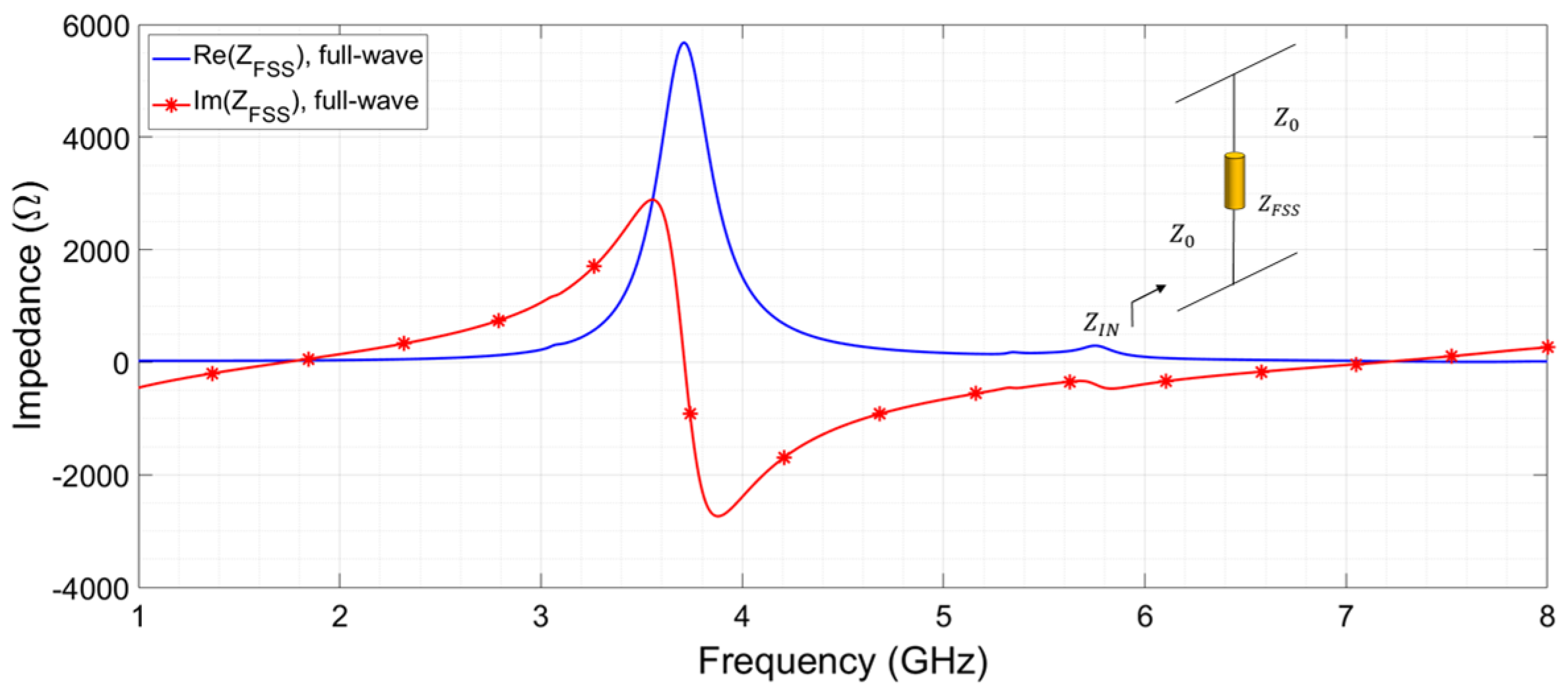
2.1. Design Procedure and Analysis of the FSS Element

The FSS layers were intentionally engineered by folding and extending the I-shaped conductive elements to optimize the performance across a broad frequency range. By incorporating meandering patterns, the unit cell introduced additional capacitance and inductance along the trace, enhancing its ability to pass a wide range of frequencies with minimal attenuation.
In addition, this configuration was meticulously designed by considering the proximity between the FSS layers, separated by an ultrathin dielectric substrate, leading to the manifestation of a parallel LC behavior necessary for achieving the bandpass filter’s functionality. This strategy, which employs the miniaturization of the I-shaped unit cell through a meandering approach, aims to enhance the effective electrical length of the unit cell within a confined space, simultaneously maximizing the corresponding Q-factor. The number of meanders was selected to achieve a periodicity of 24 mm, carefully balancing the design to prevent higher-order spurious resonances. Meanderization increases the electrical length of the unit cell without increasing its physical size, allowing for reduced periodicity and lower frequency operation. A large periodicity in FSS can lead to higher-order harmonics and unwanted interference, reducing the overall effectiveness. This approach enhances selectivity, suppresses spurious responses, and improves angular stability, enabling the design of compact FSSs with optimized performance.
The design procedure was carried out by applying the bandpass condition through exploiting the transmission line equivalent model (TLM) [39]. Figure 2a synthetizes the schematic representation of the overall double-layer FSS impedance.
The impedance seen at the input of this circuit Z I N  can be expressed as:
Z I N = Z F S S Z 0 Z F S S + Z 0
Consequently, the input impedance in Equation (1) can be substituted in the transmission coefficient expression resulting in:
τ = 2 Z 0 Z I N + Z 0 = 2 2 + Z 0 Z F S S
Since the application herein discussed consists of a bandpass filter, the transmission coefficient should ideally be equal to 1 in the band of interest, and 0 everywhere else. Thus, it is reasonable to state that the ratio Z 0 / Z F S S should be equal to 0 to achieve a transmission coefficient equal to 1. This is formalized in:
Z 0 Z F S S   0
Considering that the free space impedance is equal to Z 0 = 377Ω, then the interposed FSS must be an open circuit in the passing band, thus realizing a transparency zone. Generally, this open circuit condition is valid in small frequency intervals, resulting in narrow-band filters. Specifically, to have a transmission coefficient of at least −3 dB, the acceptable Z 0 / Z F S S ratio must be at most 2, so that τ 0.5.
A very wide transmitting band can be accomplished when the unit-cell Q-factor is maximized throughout the overall band of interest, providing a Z 0 / Z F S S ratio equal or superior to 2. To this aim, the strip line width is a fundamental parameter to achieve Q-factor maximization. Therefore, it was altered to assess the bandpass filter’s impedance variations and evaluate the Q-factor behavior.
In Figure 2b,c, real and imaginary parts of Z F S S obtained from full wave simulations by varying the strip width are reported.
The Q-factor is defined considering the resonance frequency f 0  and the −3 dB band f 3 dB (i.e., the bandwidth between the two frequencies at which the power is −3 dB below the peak value) and is calculated as follows:
Q = f 0 f 3 dB
This definition is applied to the real part of Z F S S , as shown in Figure 2a, to provide the Q-factor values for varying strip widths, which are summarized in Table 2. As the strip width increases, the Q-factor decreases, making the configuration with w = 0.2 mm the one with the highest Q-factor.
Thus, the impedance condition is satisfied over the widest frequency range possible, determining a design procedure that ensures compactness without sacrificing the wideband bandpass performance integrity.

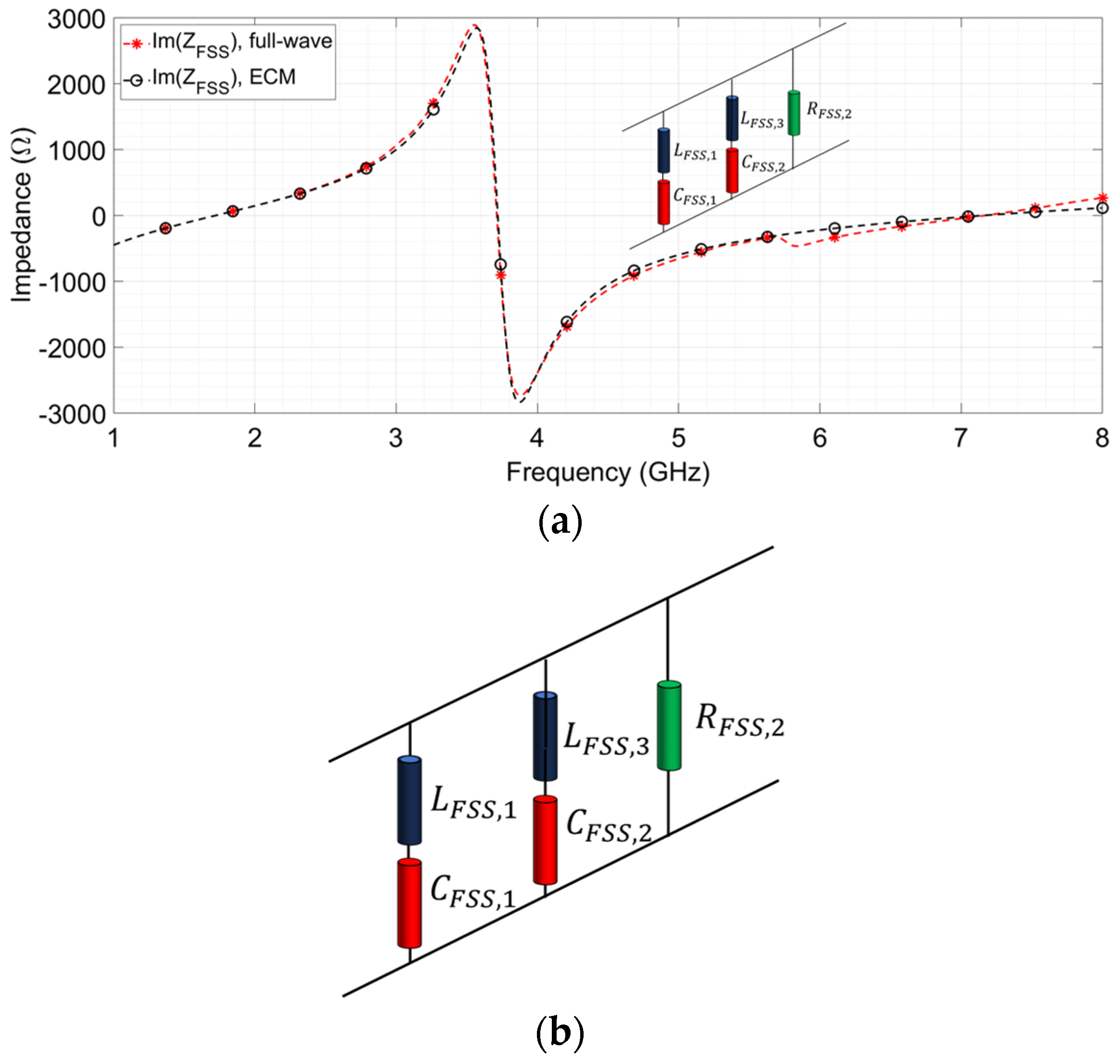
2.2. Equivalent Circuit Model Analysis

As has been widely documented in the literature, physical considerations based on an equivalent circuit model (ECM) prove highly beneficial in determining effective design guidelines for FSS filters.
In this specific case, the proposed configuration comprises two lossless layers etched on opposing sides of a dielectric substrate, whose thickness (measuring 0.003 λ L ) is sufficiently small that it can be disregarded in the ECM retrieval. The schematic representation of a typical FSS surrounded by air has previously been illustrated in Figure 2a.
Firstly, the trend of the overall double-layer FSS impedance Z F S S , obtained from full-wave simulations and normal incidence, was shown and examined to understand the corresponding circuital behavior. The real and imaginary parts of Z F S S  are illustrated in Figure 3. In the frequency interval from 1 GHz to 2.5 GHz, the FSS unit cell could be recognized as an LC series, which constitutes the first branch of the ECM and can be expressed as in Equation (5):
Z F S S , 1 = j ω L F S S , 1 + 1 j ω C F S S , 1
At this point, to retrieve the values of L F S S , 1 and C F S S , 1 from the graph reported in Figure 4a, we can adopt the following procedure.
By computing the derivative with respect to ω of the expression in Equation (5) and evaluating it at ω r e s , 1 (i.e., the first series resonance frequency, approximately 1.7 GHz, Figure 3), the value of L F S S , 1 can be obtained:
L F S S , 1 = 1 2 ω I m Z F S S , 1   a t   ω = ω r e s , 1
Consequently, the value of C F S S , 1 is established from the resonance condition:
C F S S , 1 = 1 ω r e s , 1 2 · L F S S , 1
From an operative point of view, the frequency span around the series resonance constitutes a band stop region within the L-band that can also be conveniently exploited as a ground plane for future rasorber configurations. By moving upward within the frequency range, it can be deduced that the retrieved LC series is to be positioned in parallel with a capacitance indicated as C F S S , 2 and with a resistance R F S S , 2 . The value of R F S S , 2 can be directly evaluated at the parallel resonant point, as in the following expression:
R F S S , 2 = max f R e Z F S S
It should be noticed that this resistive value is not related in its absolute value to the losses in the copper strip constituting the FSS unit-cell or in the dielectric substrate. Instead, its role is to describe the parallel resonance at 3.68 GHz, whose Q-factor is not infinite due to the realistic material employed in the numerical simulation. The value of C F S S , 2 can now be computed by calculating the value of Z F S S , 1 at ω r e s , 2 (i.e., the second parallel resonance frequency), when the series Z F S S , 1 acts as an inductance:
Z F S S , 1 = j ω L e q   a t   ω = ω r e s , 2
Hence, C F S S , 2 is determined from the second parallel resonance condition at ω r e s , 2 :
C F S S , 2 = 1 ω r e s , 2 2 · L e q
Finally, the FSS impedance shows another series resonance at ω r e s , 3 : (in correspondence with 7.2 GHz, Figure 3), so that C F S S , 2 is positioned in series with L F S S , 3 , whose value is established from the third resonance condition at ω r e s , 3 , and we can define Z F S S , 2 :
L F S S , 3 = 1 ω r e s , 3 2 C F S S , 2
Z F S S , 2 = j ω L F S S , 3 + 1 j ω C F S S , 2
The overall resulting Z F S S deducted from the analyzed ECM can be expressed as:
Z F S S = Z F S S , 1   Z 2 P Z F S S , 1 + Z 2 P
where   Z 2 P is specified in Equation (14):
Z 2 p = Z F S S , 2 R F S S , 2 Z F S S , 2 + R F S S , 2
The derived ECM is synthetized in Figure 4b. To validate the resulting equivalent circuit model, the comparison between the imaginary part of the overall Z F S S derived from the full wave simulations and the imaginary part of the analytical Z F S S reconstructed via ECM is presented in Figure 4a. Figure 4a features the superposition of the two curves, confirming the accuracy of the ECM retrieval procedure. This results in an FSS unit-cell impedance characterized by R F S S , 2 = 5 · 10 3   Ω , L F S S , 1 = 0.4   nH , L F S S , 3 = 0.12   nH ,   C F S S , 1 = 0.2   pF , and C F S S , 2 = 0.04   pF .

3. Results

To validate the design of the proposed bandpass FSS filter, comprehensive software-based full-wave simulations and experimental measurements were undertaken. These aimed to elucidate the performance of the herein described configuration in terms of transmission response.

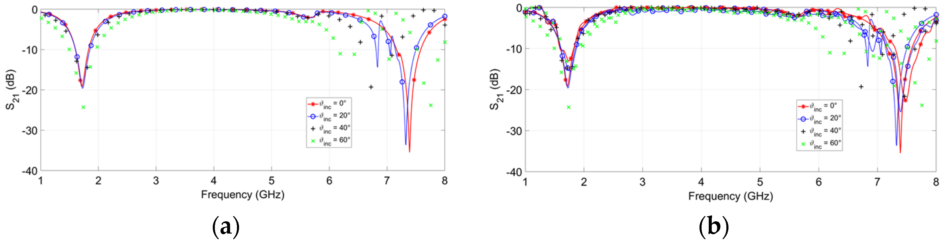
3.1. Numerical Results

The structure was analyzed by using periodic boundary conditions and standard mesh through the full-wave simulation software CST Microwave Studio (Dassault Systemes, Vélizy-Villacoublay, France).
The project template workflow was as follows: Mw and RF and optical, periodic structures, FSS, metamaterial—unit cell, phase reflection diagram, solvers frequency domain.
The study was carried out by assuming that a plane wave impinges on the top layer of the bandpass filter with different incidence angles (from 0° to 60°) and for TE polarization. Since the proposed structure is fully centrosymmetric, its response is the same at vertical incidence of TE and TM-polarized electromagnetic waves, and we will only discuss the case at TE-polarization in the subsequent analysis as well as in the experimental measurement section [40].
The transmission coefficient resulting from this investigation is depicted in Figure 5. The −3 dB fractional transmission bandwidth was evaluated equal to F B W 3 dB = 108.7 % (corresponding to the condition in which S 21 3   dB , spanning from 2 GHz to 6.76 GHz) for ϑ i n c = 0° and exceeded 90% for ϑ i n c = 40°. Performances were stable even up to ϑ i n c = 40°, with a bandpass ranging from 2.3 GHz to 5.5 GHz, resulting in a F B W 3 dB   = 85%. When the −1 dB fractional transmission bandwidth F B W 1 dB was considered (corresponding to the condition in which S 21 1   dB ), it exceeded 80% for ϑ i n c = 0°, ϑ i n c = 20°, ϑ i n c = 40°, spanning from 2.3 GHz and 5.4 GHz. The insertion loss level was approximately 0 dB (0.0007 dB) in correspondence with the central frequency (3.68 GHz).
Therefore, the structure demonstrated a wide and flat bandpass stable behavior against the incidence angle up to 40°, thus representing a very robust solution as an S-C band bandpass filter.

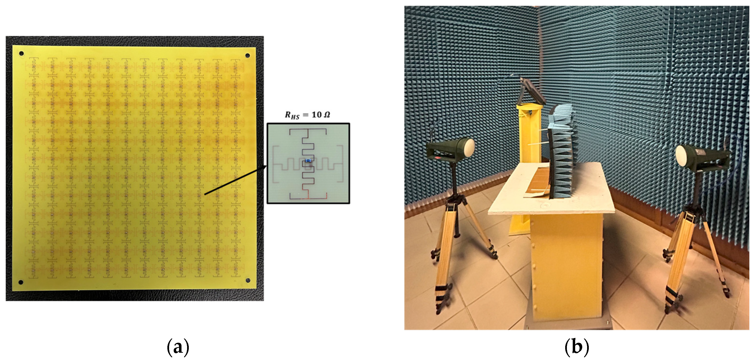
3.2. Experimental Results

Experimental measurements were performed in a microwave anechoic chamber, where a pair of horn antennas (1–9 GHz) connected to a calibrated Vector Network Analyzer (N9918A 26.5 GHz FieldFox Vector Network Analyzer, Keysight Technologies, Santa Rosa, CA, USA) were used to transmit and receive the plane wave, respectively [41]. To attain the transmission coefficient, the two antennas were placed on both sides of the prototype, equally spaced 60 cm from it. The measurements with a specific angular inclination of the plane wave were carried out by positioning the antennas according to the required orientation.
Furthermore, the prototype of the presented filter was fabricated by using printed circuit board (PCB) technology. This is represented in detail in Figure 6a and consists of a 12 × 12 unit cell panel, with an overall size of 288 mm × 288 mm. The SMD resistors were in the 0603 package and soldered on each unit cell via printed circuit board (PCB) technology. The measurement environment is reported in Figure 6b.
A slab of FR4 with dielectric permittivity ε r equal to a 4.26 and 0.46 mm thickness was employed for the prototype substrate. The FSS layers were realized in copper and printed on opposing sides of the substrate with a 35-µm etching process, as specified in Section 2.
In particular, this bandpass FSS filter exhibited a low weight of approximately 0.925 kg/m2, making it an extremely lightweight solution, ideal for applications where reduced mass and thickness are essential as airborne radomes.
The experimental results are provided in Figure 5b. It was evident that the wideband bandpass feature of the proposed FSS filter, along with the flat plateau response and low insertion loss, was also well-maintained experimentally.
By executing measurements for increasing oblique incidence angles, it is noteworthy to point out that the transmission bandwidth diminished but consistently preserved at least a 60% fractional bandwidth (FBW). Therefore, this trend showed consistency with the simulated results, confirming an excellent wideband flat bandpass property.

4. Discussion

A comparison between the proposed bandpass FSS filter and other S-C band solutions found in the literature is shown in Table 3.
The comparisons confirmed a better performance of the designed FSS in terms of thickness and angular stability with respect to the state-of-the-art, with competitive advantages concerning the fractional bandwidth (FBW) and the overall low profile. It is worth underlining that the proposed structure had the lowest thickness. When the herein-discussed FSS filter was compared with the ones in [29,30] that exhibited similar profiles, a significant improvement in the FBW could be observed.
Although the FSS in [31] showed a broader bandwidth, this was achieved by considering a hybrid 2.5D–3D unit cell, which significantly added complexity to the implementation and fabrication cost of the FSS. Only the FSSs proposed in [28,29,32] offered superior angular stability up to 60°, but with significantly reduced bandwidth.
As can be further deduced from Table 3, the other proposed works exhibited a smaller unit cell size. However, they employed multiple layers or multidimensional FSSs, thus enlarging the overall thickness of the unit cell.

5. Conclusions

An ultrathin wideband angularly stable frequency selective surface (FSS) bandpass filter covering the S-C bands was designed and carefully investigated in this paper. The filter structure comprised a multilayer bandpass metasurface obtained by interposing an ultrathin dielectric substrate between two miniaturized FSS layers.
An analytical synthesis procedure was derived by relying on an equivalent circuit model based on the transmission line theory. A prototype was designed, fabricated, and experimentally characterized for validation of the design procedure. The measured results showed good consistency with the ones obtained from the full wave simulations, thus verifying the effectiveness of the design strategy. The proposed filter exhibited a −3 dB transmission band spanning from 2 to 6.76 GHz (a 108.7% fractional bandwidth), also proving a stable response under incidence angles up to 40°.
The aforementioned configuration, due to its exceptional attributes of wideband flat bandpass, low profile, polarization insensitivity, and angular stability, holds significant potential in the field of electromagnetic shielding and compatibility. Future work will explore the integration of advanced fabrication techniques, such as screen-printing and physical vapor deposition (PVD), to further reduce the thickness of the proposed shielding structure and enhance its adaptability for application-specific requirements. Its versatility makes it suitable for a large variety of applications and contexts, including wireless communication systems, radar technology, and satellite communication platforms, guaranteeing the instrumentation’s safety and efficiency. Given the significance of practical deployment in real-world applications, future research efforts will also focus on systematically investigating and enhancing the mechanical and electromagnetic robustness of the proposed radome. Particular attention will be devoted to its integration as a conformal coating on target platforms operating in complex environments, such as the fuselage of unmanned aerial vehicles (UAVs), thereby ensuring reliable and seamless functionality in mission-critical scenarios.

Author Contributions

Methodology, F.P. and D.B.; Software, F.P.; Validation, D.B. and A.M.; Investigation, F.P.; Writing—original draft, F.P.; Writing—review & editing, F.P. All authors have read and agreed to the published version of the manuscript.

Funding

This research received no external funding.

Institutional Review Board Statement

Not applicable.

Informed Consent Statement

Not applicable.

Data Availability Statement

The original contributions presented in this study are included in the article. Further inquiries can be directed to the corresponding author.

Conflicts of Interest

The authors declare no conflict of interest.

References

  1. Chen, X.; Tan, J.; Kang, L.; Tang, F.; Zhao, M.; Kato, N. Frequency Selective Surface towards 6G Communication Systems: A Contemporary Survey. IEEE Commun. Surv. Tutor. 2024, 26, 1635–1675. [Google Scholar] [CrossRef]
  2. Jha, K.R.; Singh, G.; Jyoti, R. A Simple Synthesis Technique of Single-Square-Loop Frequency Selective Surface. Prog. Electromagn. Res. B 2012, 45, 165–185. [Google Scholar] [CrossRef]
  3. Jie, H.; Zhao, Z.; Zeng, Y.; Chang, Y.; Fan, F.; Wang, C.; See, K.Y. A review of intentional electromagnetic interference in power electronics: Conducted and radiated susceptibility. IET Power Electron. 2024, 17, 1487–1506. [Google Scholar] [CrossRef]
  4. Wang, Z.; Zhang, J.; Hou, J.; Huang, J.; Hou, Z.; Song, M.; Denidni, T.A. Wideband and Wide-Angle Switchable Spatial Filter/Shielding With Polarization-Independent Response. IEEE Antennas Wirel. Propag. Lett. 2023, 22, 1421–1425. [Google Scholar] [CrossRef]
  5. Wang, D.; Zhuang, Y.; Shen, L.; Meng, X.; Wang, G.; Tang, S.; Cai, T. Stealth radome with an ultra-broad transparent window and a high selectivity transition band. Opt. Express 2022, 30, 16009–16019. [Google Scholar] [CrossRef] [PubMed]
  6. Varikuntla, K.K.; Singaravelu, R. Design of a hybrid A-sandwich radome using a strongly coupled frequency selective surface element. Int. J. Microw. Wirel. Technol. 2020, 12, 738–748. [Google Scholar] [CrossRef]
  7. De Sabata, A.; Matekovits, L.; Buta, A.; Dassano, G.; Silaghi, A. Frequency Selective Surface for Ultra-Wide Band Filtering and Shielding. Sensors 2022, 22, 1896. [Google Scholar] [CrossRef]
  8. Ghosh, J.; Dutta, R.; Sarkhel, A.; Abbasi, Q.H. Design of miniaturize flexible wideband frequency selective surface for electromagnetic shielding application. Waves Random Complex Media 2022, 32, 1–21. [Google Scholar] [CrossRef]
  9. Wu, Z.; Xu, Y.; Liu, P.; Tian, T.; Lin, M. An Ultra-Broadband Energy Selective Surface Design Method: From Filter Circuits to Metamaterials. IEEE Trans. Antennas Propag. 2023, 71, 5865–5873. [Google Scholar] [CrossRef]
  10. Duan, K.; Chen, K.; Jiang, T.; Zhao, J.; Feng, Y. Ultrawideband Frequency Selective Radome Utilizing 2.5-D Lossy Layers. IEEE Antennas Wirel. Propag. Lett. 2023, 22, 2427–2431. [Google Scholar] [CrossRef]
  11. Yuan, H.; Brizi, D.; Mishra, V.; Fang, X.; Li, H.; Cao, Q.; Monorchio, A. A multifunctional frequency selective rasorber based on hybrid microfluidic-electronic control. J. Phys. D Appl. Phys. 2024, 57, 195002. [Google Scholar] [CrossRef]
  12. Li, H.; Feng, Y.; Zhao, M.; Wang, X.; Brizi, D.; Fang, X.; Hu, J.; Sima, B.; Zong, Z.; Wu, W.; et al. A Dual-Polarized and Wideband Switchable Absorption/Transmission Frequency Selective Surface With Multispectral Functionality. IEEE Open J. Antennas Propag. 2024, 5, 286–296. [Google Scholar] [CrossRef]
  13. Parameswaran, A.; Kundu, D.; Sonalikar, H.S. A dual polarized wideband frequency-selective rasorber with low inband insertion loss and high oblique incidence stability. IEEE Trans. Electromagn. Compat. 2021, 63, 1820–1828. [Google Scholar] [CrossRef]
  14. Yu, Q.; Liu, S.; Monorchio, A.; Kong, X.; Brizi, D.; Wu, C.; Wen, Y. A Highly Selective Rasorber with Ultraminiaturized Unit Based on Interdigitated 2.5-D Parallel Resonator. IEEE Trans. Electromagn. Compat. 2022, 64, 1585–1592. [Google Scholar] [CrossRef]
  15. Yu, Q.; Liu, S.; Monorchio, A.; Kong, X.; Brizi, D.; Zhang, X.; Wang, L. Miniaturized Wide-Angle Rasorber with a Wide Interabsorption High Transparent Bandpass Based on Multiple 2.5-D Resonators. IEEE Antennas Wirel. Propag. Lett. 2022, 21, 416–420. [Google Scholar] [CrossRef]
  16. Jiang, X.; Rashid, A.K.; Xu, W.; Cheng, Q.; Shao, L.; Zhang, Q. An Ultrawideband Three-Dimensional Bandpass Frequency Selective Surface. IEEE Antennas Wirel. Propag. Lett. 2022, 21, 1238–1242. [Google Scholar] [CrossRef]
  17. Li, H.; Li, B.; Zhu, L. Wideband Bandpass Frequency-Selective Structures on Stacked Slotline Resonators: Proposal and Synthetic Design. IEEE Trans. Antennas Propag. 2020, 68, 7068–7078. [Google Scholar] [CrossRef]
  18. Lalbakhsh, A.; Afzal, M.U.; Esselle, K.P.; Smith, S.L. All-Metal Wideband Frequency-Selective Surface Bandpass Filter for TE and TM Polarizations. IEEE Trans. Antennas Propag. 2022, 70, 2790–2800. [Google Scholar] [CrossRef]
  19. Yong, W.Y.; Glazunov, A.A. Miniaturization of a Fully Metallic Bandpass Frequency Selective Surface for Millimeter-Wave Band Applications. IEEE Trans. Electromagn. Compat. 2023, 65, 1072–1080. [Google Scholar] [CrossRef]
  20. Hong, T.; Wang, M.; Peng, K.; Zhao, Q.; Gong, S. Compact Ultra-Wide Band Frequency Selective Surface with High Selectivity. IEEE Trans. Antennas Propag. 2020, 68, 5724–5729. [Google Scholar] [CrossRef]
  21. Zhu, J.; Wang, Q.; Jin, M. High-Order Wideband Band-Pass Miniaturized Frequency-Selective Surface with Enhanced Equivalent Inductance. Electronics 2024, 13, 925. [Google Scholar] [CrossRef]
  22. Xu, S.; Li, Y.; Ahmed, M.; Fang, L.; Jin, N.; Li, B.; Huo, S.; Lei, X.; Sun, Z.; Yu, H.; et al. A Novel Miniaturized Ultra-Wideband Frequency Selective Surface with Rapid Band Edge. IEEE Access 2021, 9, 161854–161861. [Google Scholar] [CrossRef]
  23. Hu, D.; Zhai, H.; Liu, L.; Shi, J.; Nie, Z. A new miniaturized frequency selective surface designed for Ku-band absorption and low-frequency bandpass. Microw. Opt. Technol. Lett. 2020, 62, 315–321. [Google Scholar] [CrossRef]
  24. Li, J.; Hou, X.; Xu, Y. An Ultra-thin Flexible Double-Layer Dual-Band Frequency Selective Surface. J. Electron. Mater. 2023, 52, 514–522. [Google Scholar] [CrossRef]
  25. Kanchana, D.; Radha, S.; Sreeja, B.S.; Manikandan, E. A single layer UWB frequency selective surface for shielding application. J. Electron. Mater. 2020, 49, 4794–4800. [Google Scholar] [CrossRef]
  26. Can, S. Dual-band sub-6-GHz frequency filtering with optically transparent single-layer dual-polarized smart surface. Microw. Opt. Technol. Lett. 2023, 66, e33959. [Google Scholar] [CrossRef]
  27. Bharti, G.; Jha, K.R.; Singh, G.; Jyoti, R. Design of angular and polarization stable modified circular ring frequency selective surface for satellite communication system. Int. J. Microw. Wirel. Technol. 2016, 8, 899–907. [Google Scholar] [CrossRef]
  28. Shukoor, M.A.; Dey, S. Novel Dual-Mode Polarization Insensitive Wide Angular Stable Circular Ring Based Deca-Band Absorber for RCS and EMI Shielding Applications. IEEE Trans. Electromagn. Compat. 2022, 64, 1337–1345. [Google Scholar] [CrossRef]
  29. Karahan, M.; Aksoy, E. Design and analysis of angular stable antipodal F-type frequency selective surface with multi-band characteristics. Int. J. RF Microw. Comput. Aided Eng. 2020, 30, e22466. [Google Scholar] [CrossRef]
  30. Li, T.; Li, D.; Qin, P.; Fan, Y.; Gu, Y.; Zuo, P.; Sha, W.E.I.; Li, E. A Novel Miniaturized Strong-Coupled FSS Structure With Excellent Angular Stability. IEEE Trans. Electromagn. Compat. 2021, 63, 38–45. [Google Scholar] [CrossRef]
  31. Bai, H.; Yan, M.; Li, W.; Wang, J.; Zheng, L.; Wang, H.; Qu, S. Tunable Frequency Selective Surface With Angular Stability. IEEE Antennas Wirel. Propag. Lett. 2021, 20, 1108–1112. [Google Scholar] [CrossRef]
  32. Hussein, M.; Zhou, J.; Huang, Y.; Al-Juboori, B. A Low-Profile Miniaturized Second-Order Bandpass Frequency Selective Surface. IEEE Antennas Wirel. Propag. Lett. 2017, 16, 2791–2794. [Google Scholar] [CrossRef]
  33. Afzal, W.; Ebrahimi, A.; Robel, M.R.; Rowe, W.S.T. Low-Profile Higher-Order Narrowband Bandpass Miniaturized-Element Frequency-Selective Surface. IEEE Trans. Antennas Propag. 2023, 71, 3736–3740. [Google Scholar] [CrossRef]
  34. Singh, C.; Jha, K.R.; Sharma, S.K.; Jibran, Z.A.P.; Singh, G. Design of a wideband square slot bandpass frequency-selective surface using phase range analysis. Eng. Rep. 2020, 2, e12085. [Google Scholar] [CrossRef]
  35. Ma, Y.; Zhang, X.; Wu, S.; Yuan, Y.; Yuan, N. A Hybrid 2-D–3-D Miniaturized Multiorder Wide Bandpass FSS. IEEE Antennas Wirel. Propag. Lett. 2022, 21, 307–311. [Google Scholar] [CrossRef]
  36. Jian, D.; Ma, Y.; Li, Z.; Mo, J. A Miniaturized Quad-Stopband Frequency Selective Surface with Convoluted and Interdigitated Stripe Based on Equivalent Circuit Model Analysis. Micromachines 2021, 12, 1027. [Google Scholar] [CrossRef]
  37. Liu, J.; Liao, S.; Xue, Q.; Che, W. A Wide Bandpass Elliptical Filtering Response Frequency-Selective Slab Based on Slotline- Backed Split-Ring Resonators. IEEE Trans. Antennas Propag. 2024, 72, 5201–5211. [Google Scholar] [CrossRef]
  38. Chen, Y.; Wan, G.; Ma, X.; Fu, B.; Jiao, X. Frequency-Selective Rasorber for Wideband Transmission Based on Hybrid Resistive Sheet with Harmonic Suppression. IEEE Trans. Electromagn. Compat. 2024, 66, 1087–1093. [Google Scholar] [CrossRef]
  39. Costa, F.; Monorchio, A.; Manara, G. Efficient Analysis of Frequency-Selective Surfaces by a Simple Equivalent-Circuit Model. IEEE Antennas Propag. Mag. 2012, 54, 35–48. [Google Scholar] [CrossRef]
  40. Saadeldin, A.S.; Sayed, A.M.; Amr, A.M.; Sayed, M.O.; Hameed, M.F.O.; Obayya, S.S.A. Broadband polarization insensitive metamaterial absorber. Opt. Quantum Electron. 2023, 55, 652. [Google Scholar] [CrossRef]
  41. Zhu, S.; Wang, Y.; Wang, Z.; He, J.; Quan, X.; Gao, D.; Cao, Z. On the Equivalent-Circuit-Based Design of Double-Lossy-Layer Wide Transmissive Rasorbers With Ultrawide Reflection Suppression Band. IEEE Trans. Antennas Propag. 2024, 72, 4999–5010. [Google Scholar] [CrossRef]
Figure 1. The schematic diagram of the unit cell: (a) perspective view, (b) top layer, and (c) bottom layer.
Applsci 15 04887 g001
Figure 2. (a) Schematic representation of the unit cell FSS impedance. Real (b) and imaginary (c) parts of Z F S S obtained from full wave simulations by varying the strip width.
Applsci 15 04887 g002
Figure 3. Real and imaginary parts of Z F S S obtained from the full wave simulations under normal incidence.
Applsci 15 04887 g003
Figure 4. (a) Schematic diagram of the FSS unit cell equivalent circuit model. (b) Comparison between I m Z F S S obtained from the full wave simulations and I m Z F S S reconstructed via ECM.
Applsci 15 04887 g004
Figure 5. Results of the transmission coefficient of the designed bandpass FSS filter under an impinging TE plane wave with incident angles equal to 0°, 20°, 40°, and 60°: (a) simulated, and (b) measured.
Applsci 15 04887 g005
Figure 6. (a) Fabricated prototype of the bandpass FSS filter. (b) Photo of the measurement setup in the anechoic chamber.
Applsci 15 04887 g006
Table 1. Geometrical parameters of the unit cell.
ParameterValue (mm)
D24
t0.46
w0.2
L 1 2
L 2 11.6
L 3 22
L 4 3.8
L 5 1.8
L 6 2
Table 2. Values of Q for varying strip widths.
w (mm)Q
0.223.9
0.322.7
0.421.8
0.521.7
0.621.2
Table 3. Comparison of the proposed bandpass FSS filter with previous works in the literature.
PaperDimensionThicknessFractional BW (−3 dB)Angular Stability
[31]0.08λL × 0.08λL0.3λL10%60°
[32]0.11λL × 0.11λL0.021λL5%60°
[33]0.15λL × 0.15λL0.025λL54%-
[34]0.04λL × 5.7λL0.21λL130%40°
[35]0.09λL × 0.09λL0.02λL-60°
[36]0.18λL × 0.18λL0.24λL40%45°
[this
work]
0.16λL × 0.16λL0.03λL108.6%40°
Disclaimer/Publisher’s Note: The statements, opinions and data contained in all publications are solely those of the individual author(s) and contributor(s) and not of MDPI and/or the editor(s). MDPI and/or the editor(s) disclaim responsibility for any injury to people or property resulting from any ideas, methods, instructions or products referred to in the content.

