1. Introduction
In space-based gravitational wave detection programs, such as China’s “Taiji” [
1], “Tianqin” [
2], and the European Space Agency’s LISA [
3], require picometer-precision laser interferometry between satellites to detect gravitational wave signals. Achieving this precision interferometry relies on the PAAM [
4,
5], which serves to steer a laser beam to compensate for the angle generated by the relative motion of the two spacecrafts (SCs) during the approximately 10 s of flight time a laser beam will take from one SC to reach a distant SC of three million kilometers away. The TTL noise of the PAAM directly affects the detection sensitivity of gravitational wave signals [
6,
7,
8]. Its noise budget is constrained to below
in the frequency range from 1 mHz to 1 Hz, which necessitates that the interferometer’s measurement noise remains under this critical threshold to ensure the precision required for the gravitational wave detection in space.
Recent studies have advanced PAAM testing methodologies. The Albert Einstein Institute (Hannover) conducted tests on the PAAM for the LISA mission [
4]. The OPD is measured using a triangular resonance cavity. The system achieved an OPD sensitivity of
across the frequency range from 0.1 mHz to 1 Hz. However, specific details of their testing methodology, such as relevant parameters of the triangular resonance cavity or relevant experimental constraints, have not been fully reported in the publicly available literature. In our previous work, Zhu et al. [
9] constructed an equal-arm heterodyne interferometer on an optical quartz substrate with UV-bounded Super-Invar (4J32) components. However, the thermal expansion of the substrate (
and the stress relief of the UV adhesive introduced noise exceeding
at 1 mHz–1 Hz, limiting long-term stability. Schuldt et al. [
10] built a symmetric heterodyne interferometer on an aluminum baseplate (
), reporting a
precision above 0.1 Hz. However, at lower frequencies, the noise level approximately follows a 1/f trend. The low-frequency performance of the interferometer is largely limited by the thermal noise of its system [
11,
12]. Various methods have been employed to reduce the thermal noise of the system, including the reduction of optical substrate noise and the reduction of the mechanical loss of the coatings [
13,
14,
15]. These studies demonstrate that picometer precision has been achieved in the high-frequency bands through optical substrate optimization and symmetric interferometer configurations [
9,
10]. However, in the PAAM OPD measurements, the interferometer is required to have a background noise of less than
in the frequency range of 1 mHz to 1 Hz. In laboratory environments, the impact of mechanical vibrations on the interferometer primarily occurs within the 0.1 Hz to 100 Hz frequency range [
15,
16], and its magnitude is below the requirement levels for space gravitational wave detection [
17]. Therefore, this study focuses on suppressing thermal noise effects [
18,
19,
20,
21] as they primarily limit the low-frequency sensitivity in the mHz band, rather than detailing the vibration noise. In previous studies, the suppression of the PAAM OPD measurement noise is mainly focused on the substrate material optimization and the design of the interferometer optical path. Despite this progress, significant challenges remain in suppressing the low-frequency noise to meet the stringent picometer-level requirements for the PAAM OPD measurements, and the strategies to reduce the noise from the temperature fluctuations and improve the low-frequency measurement sensitivity require more detailed investigation. To the best of our knowledge, no research has been conducted on the low-frequency characteristics of interferometers that incorporate multi-layer thermal shielding and equal-arm configurations for the PAAM OPD measurement.
In this study, an integrated opto-thermal–mechanical optimization strategy is presented. This system uses a ULE substrate () as the optical platform. Hydroxide catalysis bonding (HCB) is employed to achieve stress-free bonding of the optical components. This approach reduces noise introduced by the substrate deformation and eliminates deformation from the conventional bonding layers. A symmetric equal-arm configuration design is implemented to suppress common-mode noise. Additionally, a three-layer thermal shielding system, optimized via multi-physics coupling simulations, ensures thermal stability.
2. Theory and Simulation
To maximize common-mode rejection [
10,
22,
23], we adopted a highly symmetric heterodyne interferometry to construct the interferometer.
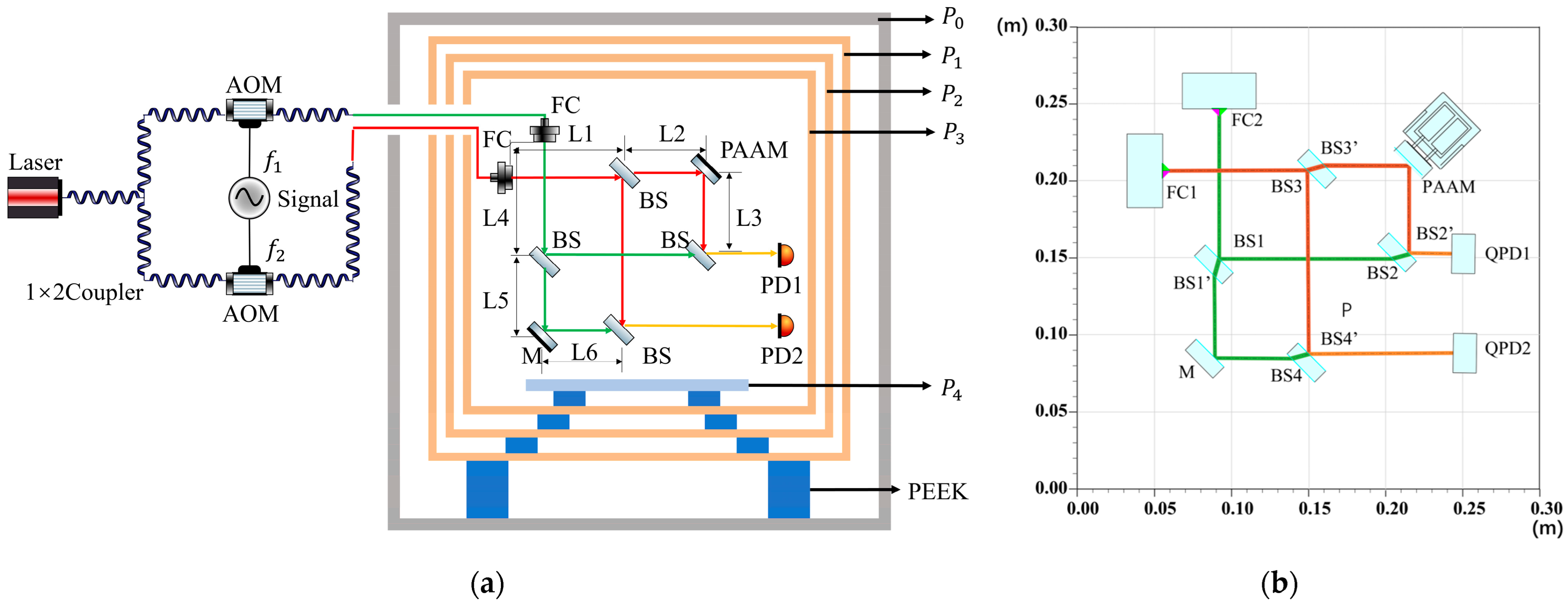
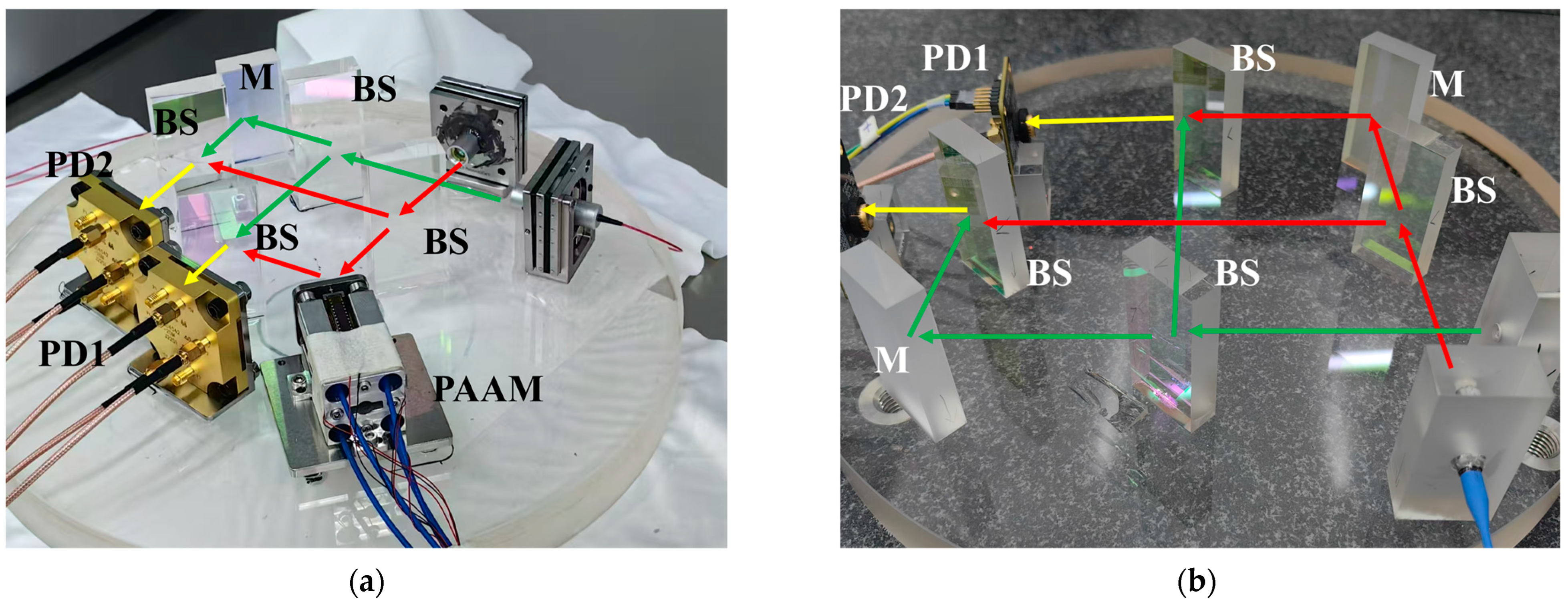
Figure 1 illustrates the layout of the entire interferometer. The system consists of a frequency modulation bench and an optical bench. The frequency modulation bench included a laser, acousto-optic modulators (AOMs), a signal generator, etc., which were used to generate two laser beams with a frequency difference of 1.6 MHz. The optical bench was situated within a multi-layer thermal shielding system placed inside a vacuum chamber.
The two modulated laser beams pass through beam splitters, the PAAM and the reference mirror, respectively, and finally combine at the beam splitters to form a heterodyne beat optical signal. The heterodyne signals are converted into electrical signals I
PD1 and I
PD2 by the detectors, and the phase difference in the optical path can be obtained by a phase meter and through the phase conversion formula (1), where
is the phase difference in radians and λ is the wavelength of the laser.
From the interference measurement path, the optical paths for the two photodetectors can be calculated as:
Thus, the optical path difference is:
To reduce the background noise level of the measurement system, we have theoretically adopted an equal-arm interferometry scheme, thereby mitigating the impact of the laser frequency noise through common-mode rejection [
22]. However, to mitigate the generation of stray light and the associated noise caused by the multiple reflections and transmissions of the laser within the beam splitter (BS), the front and rear surfaces of the BS were designed with a wedge angle of 0.5°. Considering the effects of light transmission through the BS and the wedge angle, simulations of the interferometer were conducted using IFOCAD (1.7) [
24]. The layout of the optical components was optimized to achieve a residual arm length difference of 1 nm to ensure that the optical path lengths of the reference and measurement arms were precisely matched. The simulation results are presented in
Figure 1b, with the specific optical path lengths for the reference and measurement arms detailed below:
In the formula, BS1′, BS2′, BS3′, and BS4′ denote the positions where the laser beam exits after passing through beam splitters BS1, BS2, BS3, and BS4, respectively. represents the geometrical length of the laser within the beam splitter.
The IFOCAD simulation results show that the arm length difference is 10.58 pm. Although the interferometer was designed to have an equal-arm configuration, the actual installation errors introduced a residual arm length difference (), resulting in some optical path noise.
The temperature fluctuations introduce noise through the thermal expansion of the optical substrate, and the thermal expansion and thermo-optic effects of the optical components [
18,
19,
20].
The optical path change due to the substrate thermal expansion is related to the residual arm length difference:
ΔT(t) is the temperature change and α1 is the linear expansion coefficient of the optical substrate.
Due to the symmetrical design of the system, the common-mode noise in the reference (PD1) and measurement (PD2) optical paths can be eliminated by subtraction. However, since the reference optical path passes through the BS one more time compared to the measurement optical path, the temperature change causes the beam splitter (BS) to expand and induce the thermo-optic effect, which introduces noise that cannot be eliminated by subtraction [
18,
19,
20]. Therefore, the optical path noise introduced by this difference is described by formulas (7) and (8).
The optical path noise due to the thermal expansion of the optical components is:
where α
2 is the linear expansion coefficient of the BS and n
2 is its refractive index.
The optical path noise due to the thermo-optic effect is:
where d
n/d
t is the thermo-optic coefficient, approximately
.
Thus, the optical path noise temperature induced is:
To mitigate the impact of the environmental temperature fluctuations on the phase noise of the interferometer, this study proposes a multi-layer thermal shielding system for the heterodyne interferometer. The system is designed to achieve a large time constant and low temperature sensitivity [
25,
26,
27], thereby reducing thermal noise caused by the changes in ambient temperature.
Heat transfer occurs through three primary mechanisms: heat convection, heat radiation, and heat conduction [
28]. Given that the equal-arm heterodyne interferometer operates in a vacuum environment, the influence of convection can be disregarded, and thus, heat conduction and radiation were primarily considered.
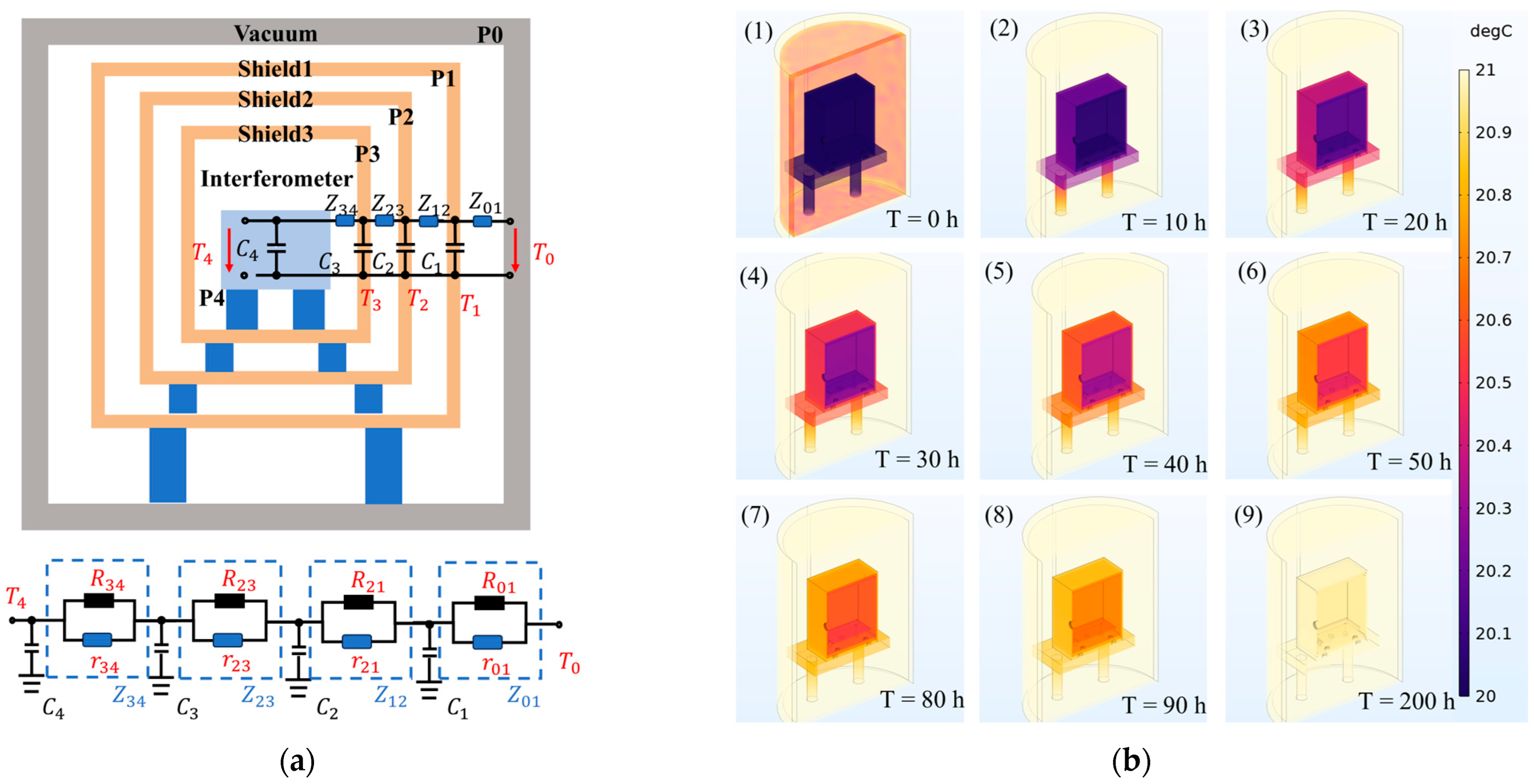
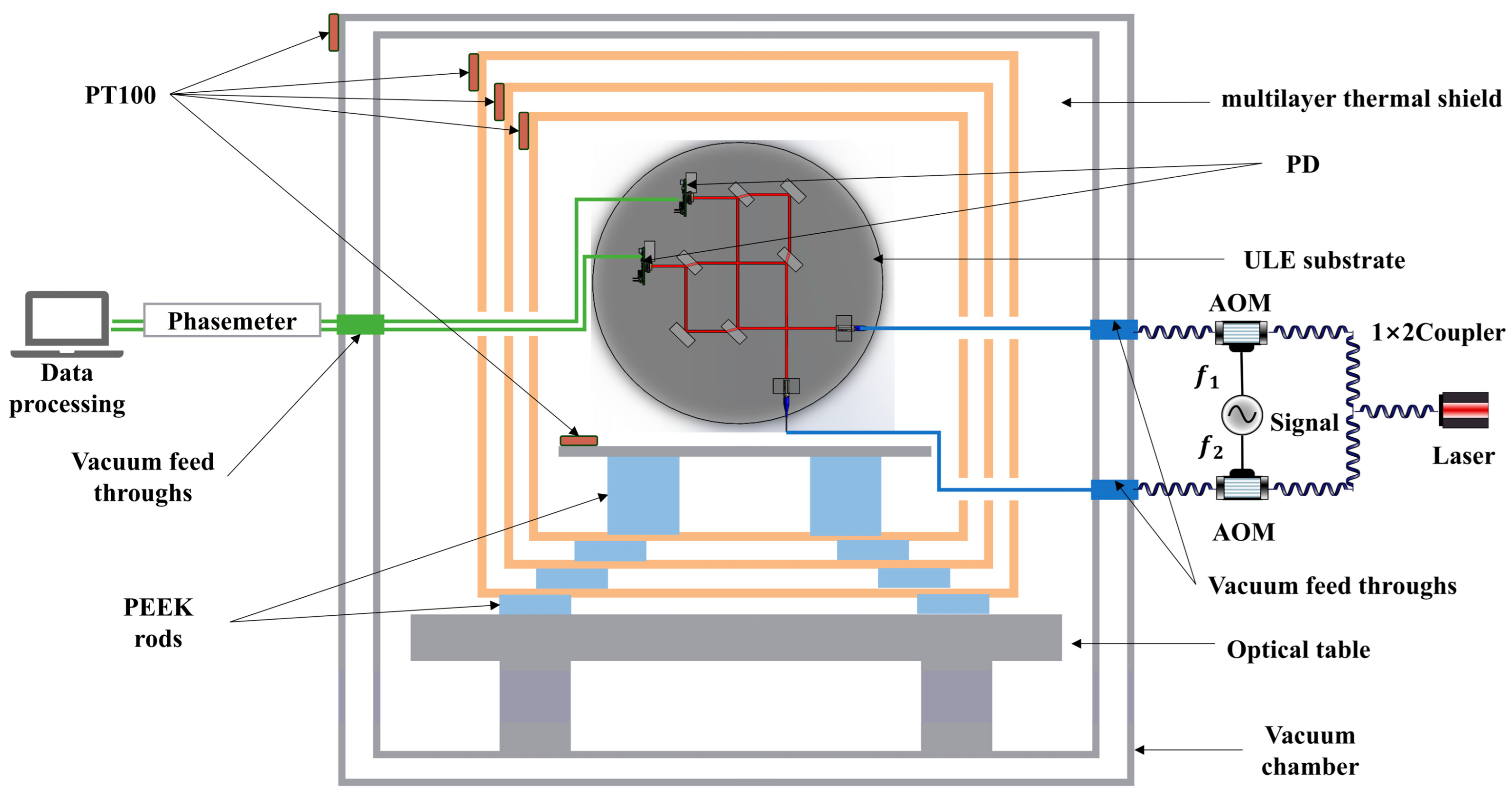
The thermal shielding system, illustrated in
Figure 2a, comprises a vacuum chamber (P
0), multiple thermal shielding layers (P
1, P
2, P
3), and the substrate for the equal-arm heterodyne interferometer’s measurement path (P
4).
The vacuum chamber, constructed from stainless steel (outer diameter 1200 mm, height 1600 mm), encloses the copper shielding layers (P
1, P
2, P
3), which are separated by polyether ether ketone (PEEK) support columns to minimize conductive heat transfer. The copper layers were polished to reduce radiative heat exchange, with detailed material properties provided in
Table 1.
In the thermal shield system, heat transfer between adjacent layers occurs through both radiation and conduction. These processes act in parallel, analogous to parallel resistors in an electrical circuit, as conceptually illustrated in
Figure 2a. The conductive thermal resistance r
ij and the radiative thermal resistance r
ij characterize these parallel heat transfer pathways [
25,
26,
27]. These combine to form the equivalent thermal impedance Z
ij between the layers, calculated as follows:
where L is the pillar height, κ
s is the thermal conductivity of the support material (PEEK), A
s is the total pillar cross-sectional area, β
ij is the heat radiation coefficient,
σ is the Stefan-Boltzmann constant, A
j is the surface area of P
j, and T
0 is the initial temperature.
The characteristic time constant quantifies the thermal response time between the adjacent layers i and j.
When the external temperature of the vacuum chamber changes from T
0 to T
f, the temperature dynamics across the shielding layers are governed by the following differential equations [
29]:
Here, Ci = ci mi represents the heat capacity of the i-th layer, where ci is the specific heat capacity and mi is the mass; Ti is the temperature of the i-th layer; αij and βij are t the conduction and radiation heat transfer coefficients between layers i and j, respectively. The conduction coefficient αij is the inverse of the conductive thermal resistance rij (αij = 1/rij), primarily associated with the heat transfer through the support pillars. This model captures both radiative (via the T4 terms) and conductive (via the linear T terms) contributions, aligning with the physical conditions of the vacuum-based interferometer setup.
Thermal simulations were performed using Finite Element Analysis (FEA) to evaluate the system’s performance. A step change in the vacuum chamber’s outer wall temperature from T
0 = 20 °C (293.15 K) to T
f = 21 °C (294.15 K) was modeled.
Figure 2b, illustrating the simulated temperature distribution at different time points, shows largely uniform temperatures within each shield layer (P
1–P
3). The profiles also visualize the progressive attenuation effect, with the temperature changes decreasing significantly layer by layer towards the substrate (P
4), substantiating the multi-layer structure’s damping effectiveness. The temperature response of the optical substrate (P
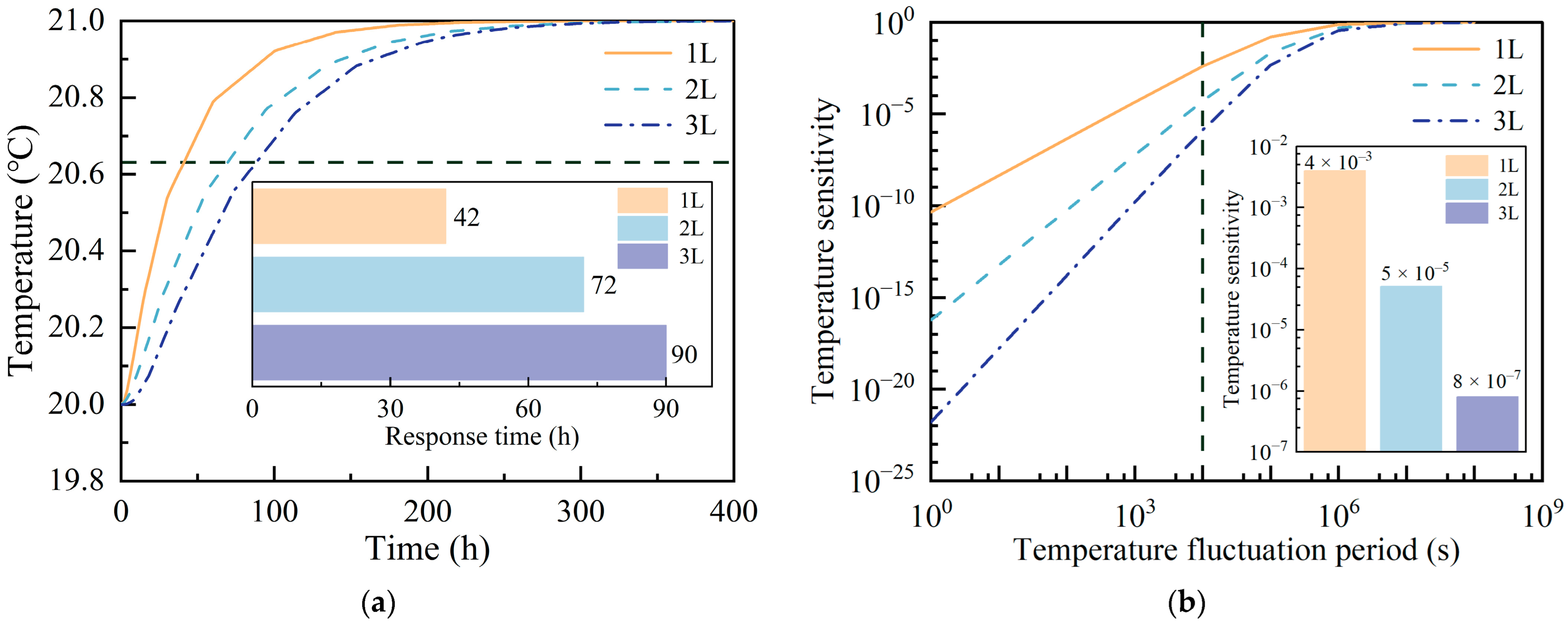
4) was calculated for the single-layer (1L), double-layer (2L), and triple-layer (3L) shielding configurations, as shown in
Figure 3a. The thermal time constant (τ) was determined as the time required for the substrate temperature to reach
. The results yielded time constants of τ
1 = 42 h for the single-layer, τ
2 = 72 h for the double-layer, and τ
3 = 90 h for the triple-layer configurations.
The progressive increase in τ with additional layers—culminating in a 58% extension for the triple-layer system compared to the single-layer design—demonstrates a slower thermal response to external disturbances. This enhancement, rooted in the multi-layer dynamics described by the above equations, effectively suppresses the low-frequency noise fluctuations in the interferometer.
Building on the thermal response simulations discussed earlier, the periodic fluctuations in the external temperature induce corresponding periodic variations in the temperature of the optical substrate along the interference measurement path. The temperature sensitivity of the substrate, defined as:
where
represents the amplitude of the substrate’s temperature variation and
denotes the amplitude of the external temperature oscillation, quantifies this relationship. For vacuum-based systems, a lower
is critical, as it directly correlates with the reduced low-frequency noise in the interferometer, thereby enhancing the measurement precision.
To further analyze this phenomenon, we simulated the vacuum system’s temperature oscillating with an amplitude
and period T. The frequency-dependent response of
, illustrated in
Figure 3b, reveals that the thermal shielding layers function as a low-pass filter, effectively attenuating the high-frequency components of external temperature fluctuations. For instance, when the external temperature varied by 1 K over a period of 10,000 s, the substrate temperature changes were approximately 10
−3 K, 10
−5 K, and 10
−7 K under single-layer, double-layer, and triple-layer shielding, respectively. These results underscore the efficacy of the multi-layer thermal shielding system in suppressing the impact of external temperature perturbations on the interferometer. As the number of shielding layers increases, the system’s temperature sensitivity is significantly reduced, bolstering its resilience against thermal disturbances and laying a foundation for improved interferometric stability in subsequent analyses.
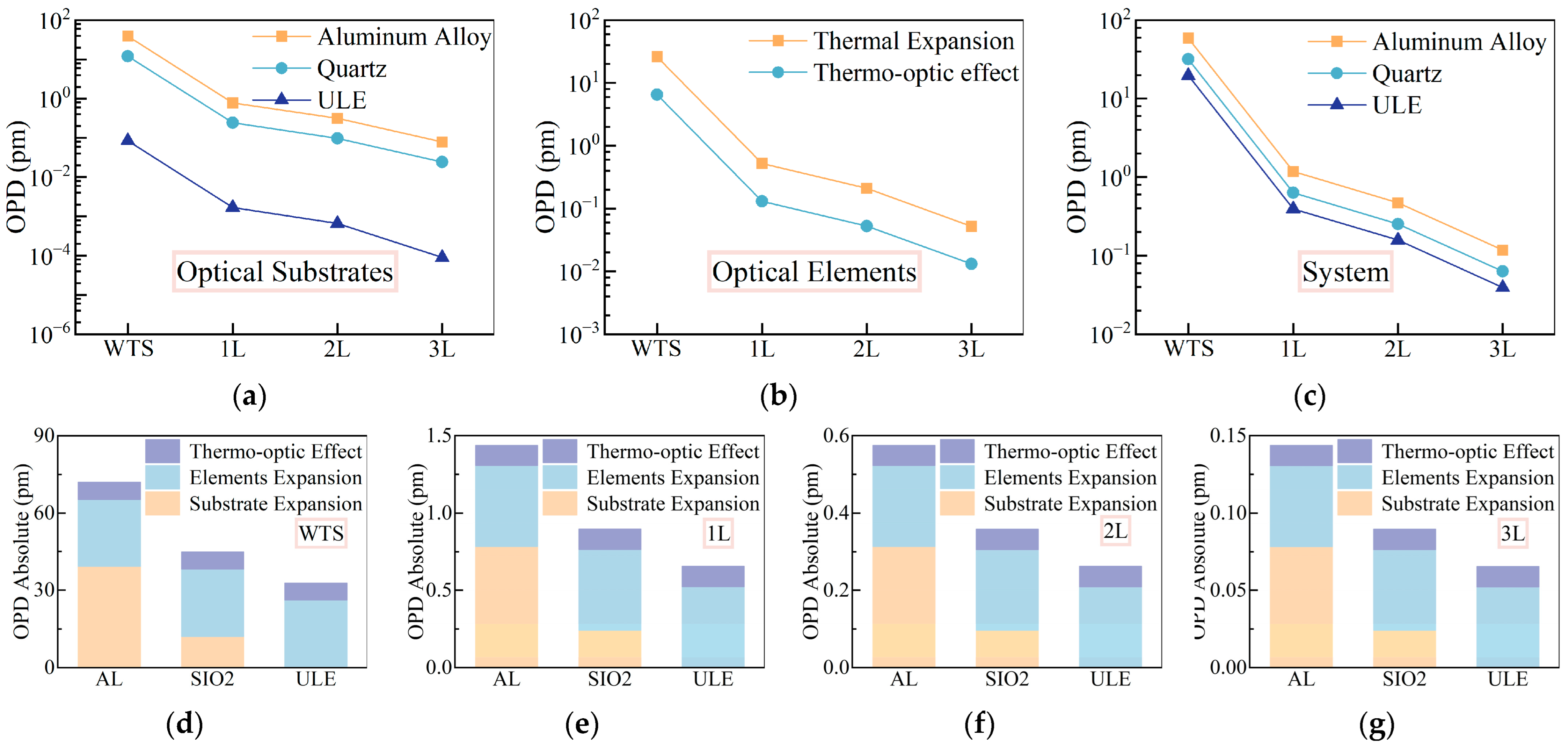
To quantify the synergistic effect of thermal shielding optimization, this study used IFOCAD to simulate the interferometer and analyzed the optical path noise under temperature disturbances for interferometers with substrates made of aluminum alloy (6061-T6), quartz glass, and ULE glass, with material parameters as shown in
Table 2 The results, as shown in
Figure 4, illustrate the noise contributions arising from substrate expansion, optical elements, and the total system under different thermal shielding configurations.
The thermal expansion coefficient
of the substrate directly influences the expansion noise
, as described by Equation (7).
Figure 4a shows that, without thermal shielding, the aluminum alloy substrate exhibits the highest expansion noise (39.22 pm), contributing 66.7% of the total system noise. This is consistent with its large
. Quartz, with
, reduces this noise to approximately 30.9% of the aluminum alloy’s value, while ULE’s near-zero
renders its expansion noise negligible (0.085 pm). Consistent with Equation (7), our findings show that the optical path change due to the substrate’s thermal expansion (
) scales linearly with the substrate’s thermal expansion coefficient (
) under constant temperature change and residual arm length difference. This highlights the importance of low-expansion substrates in minimizing thermal noise.
The noise from the optical components, as shown in
Figure 4b, arises from the thermal expansion (
) and thermo-optic effects (
), both proportional to
per Equations (8) and (9). This noise is independent of the substrate material but becomes the dominant contributor when
is minimized, such as with ULE or enhanced thermal shielding. The refractive index-related noise
, though minor, increases slightly with more shielding layers due to residual temperature gradients. However, as thermal shielding reduces
, the overall noise from the optical components decreases, as predicted by Equation (10).
The total system noise
, depicted in
Figure 4c, decreases linearly with the reduction in
afforded by the additional shielding layers. This behavior directly follows from Equation (10), where
. The progressive noise reduction with the one-, two-, and three-layer shielding configurations confirms the efficacy of multi-layer designs in attenuating thermal fluctuations and, consequently, suppressing noise.
By integrating a three-layer thermal shielding system with a ULE substrate, the system’s thermal time constant was extended to 78.5 h, significantly reducing . Coupled with ULE’s minimal , this design suppressed thermally induced optical path noise to sub-picometer levels. These results are in strong agreement with the theoretical framework established in Equation (10), validating the approach and highlighting the synergistic benefits of shielding and material selection for stabilizing interferometric measurements.
3. Experimental Results and Discussion
In our previous study [
9], as shown in
Figure 5a, to evaluate the background noise of the interferometer, we did not apply a voltage to the PAAM, keeping the steering mirror stationary, which acts as a reflector in this case. In this study, we used a reflector with a center height consistent with the PAAM instead of the PAAM for the system background noise test.
In
Figure 5b, the experimental system is shown, where key optical components such as fiber couplings and detectors were fixed to the surface of a ULE substrate (Corning
® ULE
®7973, Φ280 × 25 mm) using custom-made fused silica fixtures. The laser source was a custom-built 1064 nm laser. Two acousto-optic modulators (AOM, CETC SGTF150-1064-1P, CETC, Beijing, China) were used to apply frequency shifts of 150.8 MHz and 149.2 MHz, respectively, producing a 1.6 MHz heterodyne beat signal. A commercial phase meter (Liquid Instruments, Moku: Pro, Lyneham, Australia) was employed, along with a phase-locked loop (PLL) algorithm with a sampling frequency of 150 Hz. The entire optical path used polarization-maintaining fibers (PMF) to ensure polarization stability.
To address the thermal noise in the low-frequency range (1 mHz to 1 Hz), this study differed from traditional approaches that utilized Invar steel as the substrate. Instead, it utilized a ULE substrate (
) and Hydroxide Catalysis Bonding (HCB) [
30] technology to construct the optical path, as shown in
Figure 5b. The bonding surfaces were super polished to achieve a surface form accuracy of λ/10 (@633 nm), and in the HCB process, a bonding layer with a thickness of less than 10 nm was formed [
31].
The experimental system was placed inside a vacuum chamber with a base vacuum level of 10
−5 Pa and an operational vacuum level of 10
−2 Pa, as shown in
Figure 5b. It consisted of a composite thermal shielding system comprising three layers of copper thermal shielding (P
1, P
2, P
3) and PEEK brackets. The optical substrate was suspended within the shielding layers using PEEK brackets to minimize heat conduction. PT100 temperature sensors were installed in each layer (P
1, P
2, P
3) and the optical substrate (P
4) for real-time temperature monitoring, as depicted in
Figure 6.
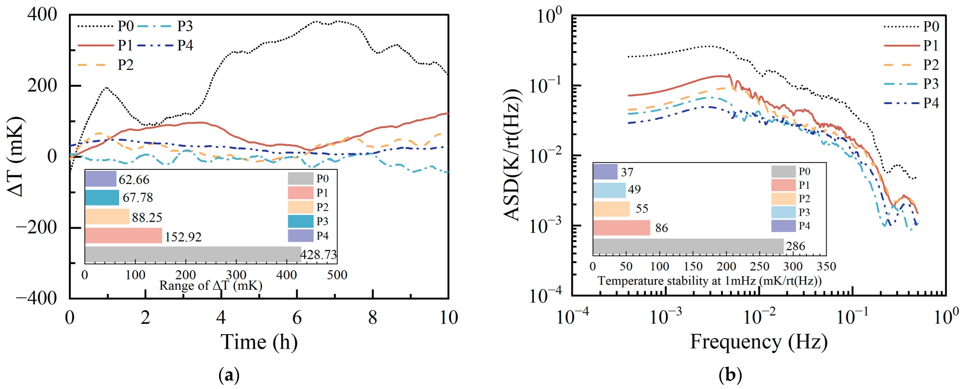
The performance of the composite thermal shielding system in mitigating temperature fluctuations was assessed by monitoring the temperature variations across the vacuum chamber (P0), the three copper thermal shielding layers (P1, P2, P3), and the optical substrate (P4) over a 10 h period.
The time sequence curves, illustrated in
Figure 7a, depict the peak-to-valley (PV) temperature fluctuations for each layer. The recorded PV values were as follows: 428.73 mK for P
0, 152.92 mK for P
1, 88.25 mK for P
2, 67.66 mK for P
3, and 62.66 mK for P
4. The vacuum chamber (P
0) exhibited pronounced temperature oscillations, with multiple peaks and troughs observed within the 10 h timeframe, reflecting its exposure to external thermal influences. In contrast, the thermal shielding layers progressively attenuated these fluctuations. Specifically, P
1 reduced the fluctuation amplitude by approximately 64.3% relative to P
0, with a noticeable slowing of the fluctuation trend. Further suppression was achieved by P
2 and P
3, which lowered the amplitudes by approximately 79.4% and 84.2%, respectively, compared to P
0. The optical substrate (P
4) displayed a nearly linear temperature profile with no discernible fluctuations, demonstrating the shielding system’s effectiveness in isolating the substrate from the external thermal disturbances.
To further evaluate the system’s ability to suppress the low-frequency thermal noise, an amplitude spectral density (ASD) analysis was conducted, as shown in
Figure 7b. At a frequency of 1 mHz, the temperature noise levels were measured as follows:
for P
0,
for P
1,
for P
2,
for P
3, and
for P
4). Relative to P
0, the thermal shielding layers reduced the temperature noise by approximately 69.9% for P
1, 80.8% for P
2, 82.9% for P
3, and 87.1% for P
4. These results highlight the multi-layer shielding system’s capability to significantly attenuate the low-frequency thermal noise, with each successive layer enhancing the thermal stability of the optical substrate.
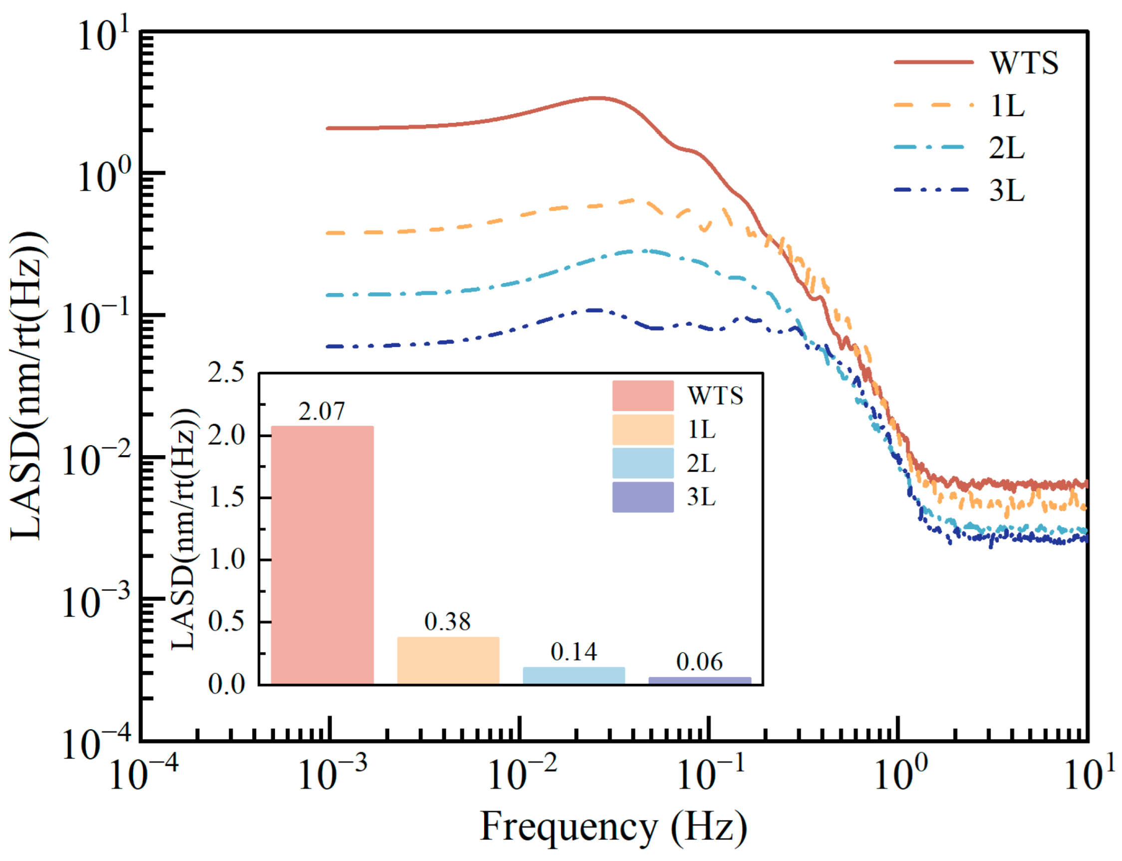
To quantify the improvement effect of the thermal shielding system on the measurement precision of the interferometer, this study measured the system’s local noise under the conditions of without thermal shielding (WTS), single-layer thermal shielding (1L), double-layer thermal shielding (2L), and triple-layer thermal shielding (3L). The correlation between the number of thermal shielding layers and the characteristics of thermal noise was analyzed using the data of displacement noise amplitude spectral density (as shown in
Figure 8). The experimental data show that at the characteristic frequency of 1 mHz, the noise for single-layer, double-layer, and triple-layer thermal shielding is
,
, and
, respectively, achieving noise suppression rates of 81.1%, 93.9%, and 97.1% compared to the no thermal shielding state (
).
Meanwhile, in the high-frequency segment, the system’s noise shows a decreasing trend as the number of layers increases. This phenomenon may be attributed to the reduction in electronic noise coupling resulting from improved thermal stability; when the temperature fluctuations of the interferometer system are effectively suppressed, such noise sources as dark current fluctuations and thermoelectric drift in the photoelectric detectors and circuits are reduced [
32].
This study, through the synergistic optimization design of multi-layer thermal shielding and low-expansion materials, achieved a background noise of
at 1 mHz, which is a reduction of 84.6% compared to previous research [
9] of
. The three-layer thermal shielding system extended the thermal time constant to 78.5 h (a 58% increase compared to the single-layer system) and effectively suppressed thermal-induced phase noise by reducing temperature sensitivity.
However, the current system’s background noise in the 1 mHz to 1 Hz frequency range is still higher than and does not meet the requirement for direct measurement of the OPD of the PAAM. The main limitations are from the vacuum environment, mechanical installation errors, and detector thermal noise. In this study, the experimental system’s fixed vacuum degree was only 10−2 Pa, and the residual gas refractive index fluctuations introduced additional noise. Through the IFOCAD simulation, when the lens installation position deviation is ±1 mm and ±5 mm, under temperature fluctuations, the noise introduced by Formula (12) is 1.40 pm and 3.55 pm (with ∆T = 20 mK), respectively. Additionally, in long-term measurements, the heat generated by the photoelectric detector causes the internal temperature of the shielding layer to rise (measured ∆T ≈ 0.1 K/h), introducing extra thermal noise and thus affecting the measurement precision.
