1. Introduction
The great success of fully mechanized mining with a large mining height of 8 m and above in Mongolia and Shaanxi proves the feasibility of this technology for thick coal seams. This technology is conducive to centralized production, with advantages such as high yield, high efficiency, fewer roadways, and a simple system. The thickness of Huoxi Coalfield is 7.5~9.3 m with an average of 8 m. In actual engineering, equipment reliability, coal seam depth, mining conditions, etc., are important bases for determining whether fully mechanized mining with a large mining height can be adopted, where coal wall stability is one of the main factors for the efficient advancement of coal mining [
1,
2,
3,
4]. As Huoxi Coalfield is characterized by a thick coal seam and roofs, the adoption of fully mechanized mining with a large mining height will bring about slight roof caving and serious spalling [
5,
6,
7].
Spalling of coal walls is a traditional problem in mining engineering, greatly restricting the development of coal mining. Upon analysis of the mechanism of spalling, Yin Xiwen [
8,
9], Yan Shaohong [
10], and Ning Yu et al. [
11] adopted the theory of idealized rods to locate the spalling of coal walls; Yuan Yong et al. [
12] analyzed the mechanism of coal wall failure on the working face with large mining height under three soft conditions, and proposed to extend the study of coal wall stability from a simplified plane problem to a treatment of a three-dimensional space, thereby establishing a mechanical model of wedge-shaped sliding bodies; Wang Jiachen et al. [
13,
14,
15] revealed the mechanical causes of spalling in different forms from the angle of coal wall failure. The coal wall instability in fully mechanized mining with a large mining height is the result of a series of behaviors such as transfer of dynamic load and deformation. In order to control the risk of instability of the coal mining face, the Wang Guoufa [
16], an Academician of Chinese Academy of Engineering, established a theoretical system involving face support and hydraulic support based on the coupling between the working face support and the brackets. Wang Jiachen and Yang Shengli et al. [
17] proposed flexible reinforcement engineering for preventing and controlling hard coal wall failure, which provided a lot of experience in controlling coal wall stability.
In the early days of the development of deep coal mining technology, roof-cutting technology was mainly used to control intense mine pressure [
18,
19]. The former Soviet Union first proposed roof-cutting technology and achieved successful applications. In the 1950s, China began to pay attention to roof-cutting technology and successively carried out experimental research. Due to its advantages, such as high safety and easy operation, it has been vigorously promoted and has now become an important research direction for mining in China. Among them, Academician He Manchao and others [
20,
21], based on different mine conditions, through a large number of verifications, proposed the theory of roof cutting short cantilever beams, artificially changing the structure of the overburden bearing beam. Chen Shangyuan and others [
22], through the derivation of theoretical formulas, obtained the method for determining the key parameters of roof cutting. With the joint efforts of many scholars, China has made great progress in the theory of roof cutting, and gradually discovering other functions of roof cutting, providing a scientific theoretical basis and data support for the further promotion and deepening of the application of roof-cutting technology.
At present, academic research on spalling and its control in Huoxi Coalfield often focuses on top coal caving. Although scholars have studied the law of mineral pressure, the characteristics of migration of overburden, and the support technology of mining with a large mining height [
23,
24,
25,
26,
27], the simple “application” of existing experience cannot completely solve the problem of mining face spalling in Huoxi Coalfield. Therefore, there is an urgent need to study the mechanism and control of spalling in fully mechanized mining with a large mining height in Huoxi Coalfield.
In view of the thick coal seam, high sulfur, and thick hard limestone roofs in Huoxi Coalfield in Shanxi, this paper analyzes the mechanism of spalling on 8 m fully mechanized mining face in Huoxi Coalfield through theoretical analysis and numerical calculation. The primary objective of this study is to thoroughly reveal the mechanism of production coal face spalling in the 8 m high longwall panel of Huoxi Coalfield. The analysis of the impacts of dirt bands, working face advancement, and roof cutting on spalling is a crucial step in achieving this objective. By conducting an analysis of these influencing factors and fully understanding their mechanisms of action, we can provide a solid theoretical basis for the formulation of effective control measures, thereby enhancing the safety and efficiency of high longwall mining operations in the Huoxi Coalfield.
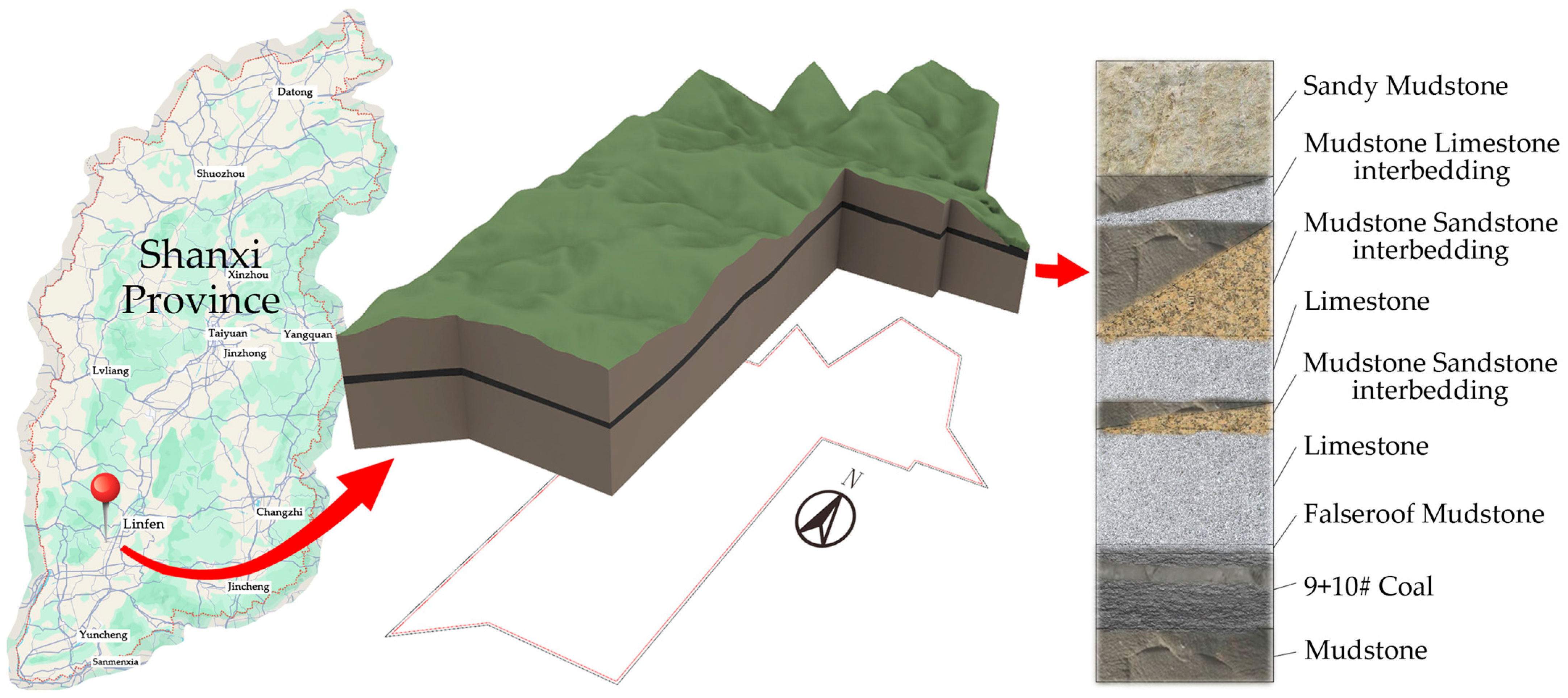
Xinyuan Coal Mine is located at the junction of western Yaodu District and Puxian County, Linfen, Shanxi. The well field contains a total of 15 coal seams. The schematic diagram of the mining area and typical columnar diagram are shown in
Figure 1. The spacing between the No. 9 and No. 10 coal seams is 0.86 m on average, which can be regarded as dirt bands. The No. 9 and No. 10 coal seams are combined and collectively referred to as the No. 10 coal seam. According to the geological data of 39 pioneer wells, the thickness of the No. 10 coal seam in Xinyuan Coal Mine is 6.11~10.15 m with an average of 7.19 m, including 1~6 dirt bands. The industrial test of fully mechanized mining with a large mining height was carried out on the 10101 working face, and backward integrated mechanized mining with total caving and a large mining height of 8 m was adopted. The roof and bottom plates of the 10101 working face are shown in
Table 1.
2. Analysis of Failure Coal Seam Area on the Fully Mechanized Mining Face
The spalling of the fully mechanized mining face is a gradual destruction that originates from the tensile failure on the coal wall and develops in the direction of excavation under the action of the top migration. Different geological conditions and mining methods also have a certain impact on the working face stability. This section analyzes the carrying characteristics of coal walls during fully mechanized mining with a large mining height in Huoxi Coalfield.
2.1. The Post-Peak Carrying Characteristics of Coal Seam on the Fully Mechanized Mining Face
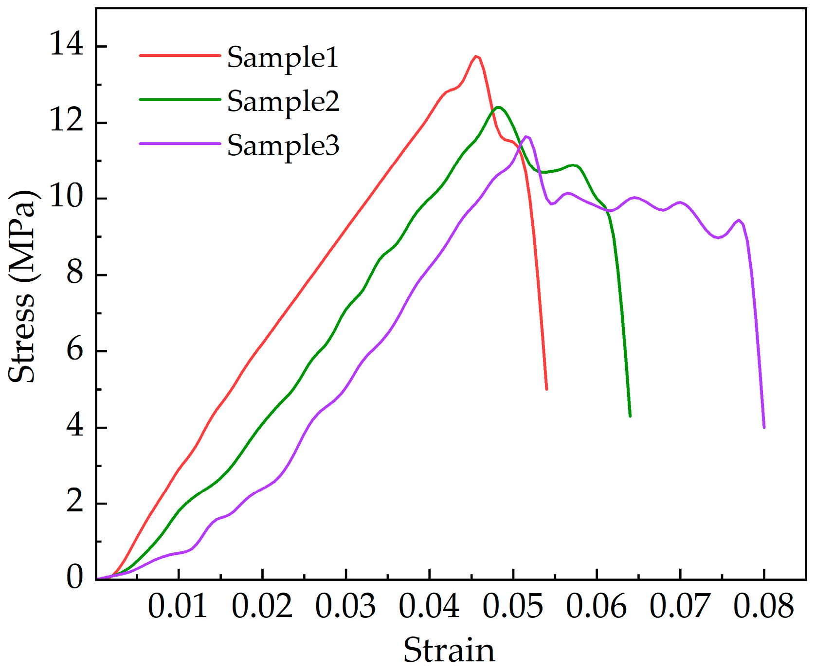
The coal seams in Huoxi Coalfield are hard coal and are brittle and easily damaged under pressure. To analyze the carrying characteristics of the coal seam, numerical simulation software was used to create samples with a height of 1 m, 3 m, and 5 m and an aspect ratio of 1:2. Uniaxial compression tests were performed for the samples of different sizes, and the simulation results are shown in
Figure 2. Under pressure, the coal samples underwent elastic deformation–plastic deformation–instability failure. It can be seen that when the test coal sample was 1 m wide, it underwent smooth transitions in the uniaxial compression test, and immediately lost compressive strength after reaching the peak, without significant plasticity changes; when the coal sample was 3 m wide, it underwent fluctuations in the stress–strain in the uniaxial compression test with reduced strength to a certain extent, and presented a plastic plateau during the compression; when the width of the coal sample was increased to 5 m, the uniaxial compressive strength further decreased, but the plastic plateau after the peak was significantly increased.
By analyzing the stress–strain curve of coal samples of different sizes, it can be concluded that the peak of the stress–strain curve decreases with the increase in size. This is because compared with small-size coal samples, there are more structural cracks inside large-size coal samples, and they are more uniformly distributed, which causes the coal samples to easily reach the compression limit; the larger the size of coal sample, the more obvious the plastic plateau is. This is because the cracks inside the coal seam resulted in a pressure difference inside the coal seam. The larger the size, the longer the pressure transfer takes, during which roof pressure will not directly crush the entire coal seam but gradually apply the loads with the transfer of pressure difference. Since the upper coal seam directly bears the pressure of roof, it is most prone to failure.
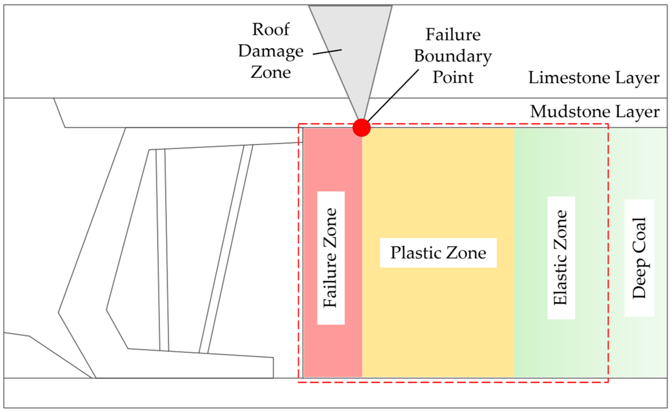
2.2. Division of Coal Seam Damage Areas on the Working Face
During mining, due to the presence of a goaf area, the coal seam at the front end of working face formed a two-way stress, and the roof, hydraulic support, bottom plates, and coal seam of the working face reached a local balance after the dynamic pressure was stabilized. The coal wall failure in the mining direction was simplified into a two-dimensional plane strain problem. Due to the large thickness of the coal seam in Huoxi Coalfield, the pressure produced a plastic plateau, which formed a significant plastic zone. At the same time, owing to the different roof pressure, the area close to the deep coal seam without plastic deformation was the elastic zone, and the coal seam which endured a force exceeding the limit on the side of goaf zone was the failure zone, where the intersection of the plastic zone and the failure zone was the failure boundary point. When determining the failure boundary point, the crack development and residual bearing capacity should be considered at the same time. Usually, it is the starting point of the force transmission path closest to the coal wall.
After the failure boundary point was determined, the area that was considered without the endurance of the force of coal seam at all was defined as the failure zone; the area where there was fracture development but still served as the main bearing part was defined as the plastic zone; the crack zone of roof formed by the advanced working face was defined as the roof damage zone, and the area close to the original rock conditions without plastic changes is the elastic zone. The schematic diagram of the division of failure zones of the coal seam at the front end of the fully mechanized mining face is shown in
Figure 3.
The state of the failure zones directly reflects the degree of coal wall failure during the coal mining process. The coal wall failure in Huoxi Coalfield is often wedge-shaped. The larger the failure zone, the greater the depth of spalling and the more serious coal wall instability is; the force and crushing in the plastic zone reflect the distribution of roof pressure on the coal seam, which, in turn, reflects the carrying state of the coal wall. In the plastic zone, in addition to crack development due to normal vertical compression, when the pressure on the roof is severe and concentrated, there is also oblique crack development in the coal seam. When a large number of oblique cracks occur, this indicates that the roof is at risk of advance caving. After analysis of the state of cracks in the roof failure zone, countermeasures should be timely adopted to prevent the risk of sudden pressure on the support. In summary, a “one point four zone” comprehensive analysis of the front-end coal wall can assess the coal wall’s stability.
3. The Scheme for Simulating Fully Mechanized Mining with a Large Mining Height
This study uses the DEM software PFC2D (v5.00.25) to conduct a numerical simulation of the spalling problem in the fully mechanized mining face with a large mining height of 8 m in Huoxi Coalfield. The simulation contents include the influence of different dirt bands on the spalling of the production coal face; the variation in the spalling pattern with the mining progress during the mining process of the working face; and the analysis of the spalling pattern of the coal face under the roof-cutting condition. The greatest advantage of using this software lies in its ability to simulate the inhomogeneous characteristics of coal and rock, reproduce the entire dynamic movement process of deformation, separation, fracture, caving, and compaction experienced by the overburden during its movement, and track the development process of mining induced fractures. All of the above endow it with the ability to reveal the movement pattern of the overburden and the spalling pattern of the production coal face.
3.1. Model Building
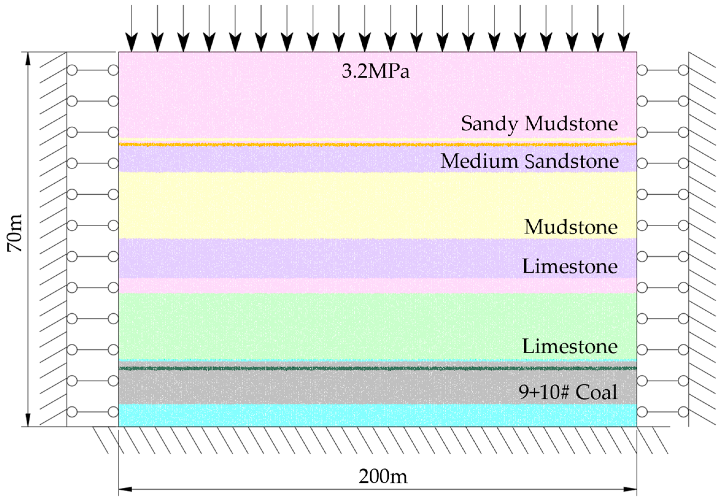
According to the actual situation of the Xinyuan Coal Mine, and by reference to the comprehensive histogram, a DEM model was established along the working face. The model is 200 m wide and 70 m high, with 14 coal seams. In fully mechanized mining with a large mining height, the No. 9 and No. 10 coal seams were mined as one, with a mining thickness of 8.5 m. A uniform load of 3.20 MPa was applied to the top of model according to the theory of overburden gradient.
Given the boundary effect, mining was located 50 m away from the model boundary. At the same time, vertical and horizontal displacement constraints were applied to the lower, left and right boundaries of the model to limit the degree of freedom of the boundaries. mining was advanced rightward along the coal seam with a drilling footage of 10 m to simulate coal cutting on the working face. The characteristics of overburden migration and mining face spalling during the advancement of the working face were analyzed. The model load and boundary conditions are shown in
Figure 4.
3.2. Calibration of Micro Parameters
In this model, the particles were bonded in a parallel manner. In calibrating the micro parameters of the large-scale model particles, the particles are obviously much larger than those of the standard sample. Therefore, the building of a model according to the size of the standard sample cannot obtain the accurate microscopic parameters that meet the actual conditions. In order to calibrate the parameters in line with the actual situation, a rectangular test block with a height of the coal seam and a width of 1/2 the height of coal seam was used to increase the pressure. The calibration methods were uniaxial compression experiment, biaxial compression experiment, and the Brazilian splitting test. The calibration covers the effective elastic modulus of parallel bonding, tensile strength, cohesion, etc. The lithology and macroscopic mechanical parameters of the rock formation are shown in
Table 2, and the calibration results of the microscopic parameters of each rock formation are shown in
Table 3.
3.3. Hydraulic Support Simulation Method
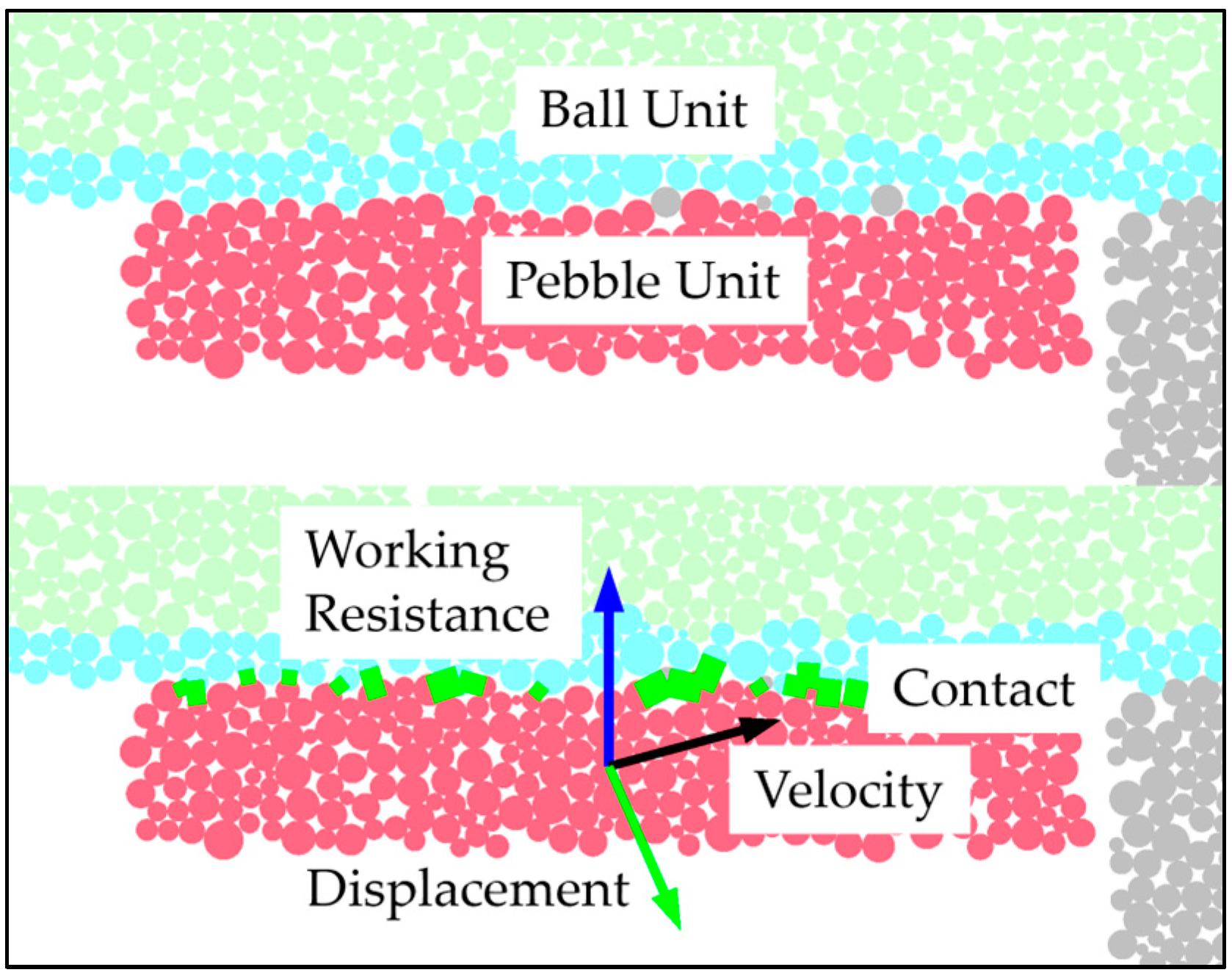
Due to the limitations of the DEM numerical simulation, the top hydraulic bracket cannot be guaranteed to be smooth. Therefore, it is difficult for the newly built support unit to keep good contact with the roof and bottom plates. In order to prevent stress concentration in the bonding between the support and the roof and bottom plates, the hydraulic support was built with rigid support units in the numerical simulation. Specifically, the information of the particles at the hydraulic support was recorded during model building. A hydraulic support with full contact with the roof and bottom plate was constructed with rigid cluster units in situ, as shown in
Figure 5.
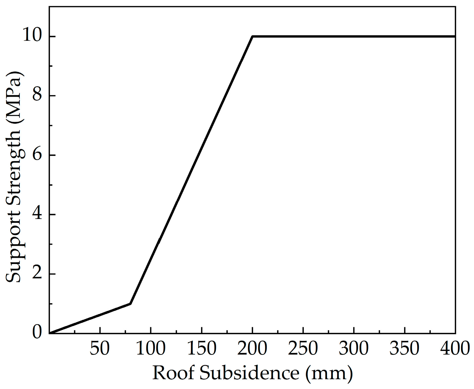
The support force of the hydraulic support underwent three stages of changes: the initial support force formed by tightening; the increase in the working resistance before the opening of the safety valve; and the constant resistance after the opening of the safety valve. According to the parameters of the hydraulic support of the mine, the roof width of the hydraulic support is set to be 2 m; the support length is 6 m; the working resistance is 12,000 kN; and the average support strength is 10 MPa. In order to meet the requirements of large mining height and the strong mine pressure, the support strength is matched according to the sinking volume of the roof to simulate the increased resistance and constant resistance of the hydraulic support at different stages so that the hydraulic support is in a working state with low initial support and high working resistance to provide effective support to failures. The curve of the simulated support strength with the sinking volume is shown in
Figure 6.
4. Simulation Results of Fully Mechanized Mining with a Large Mining Height and the Analysis
4.1. Characteristics of the Failure of Coal Face at Different Dirt Bands
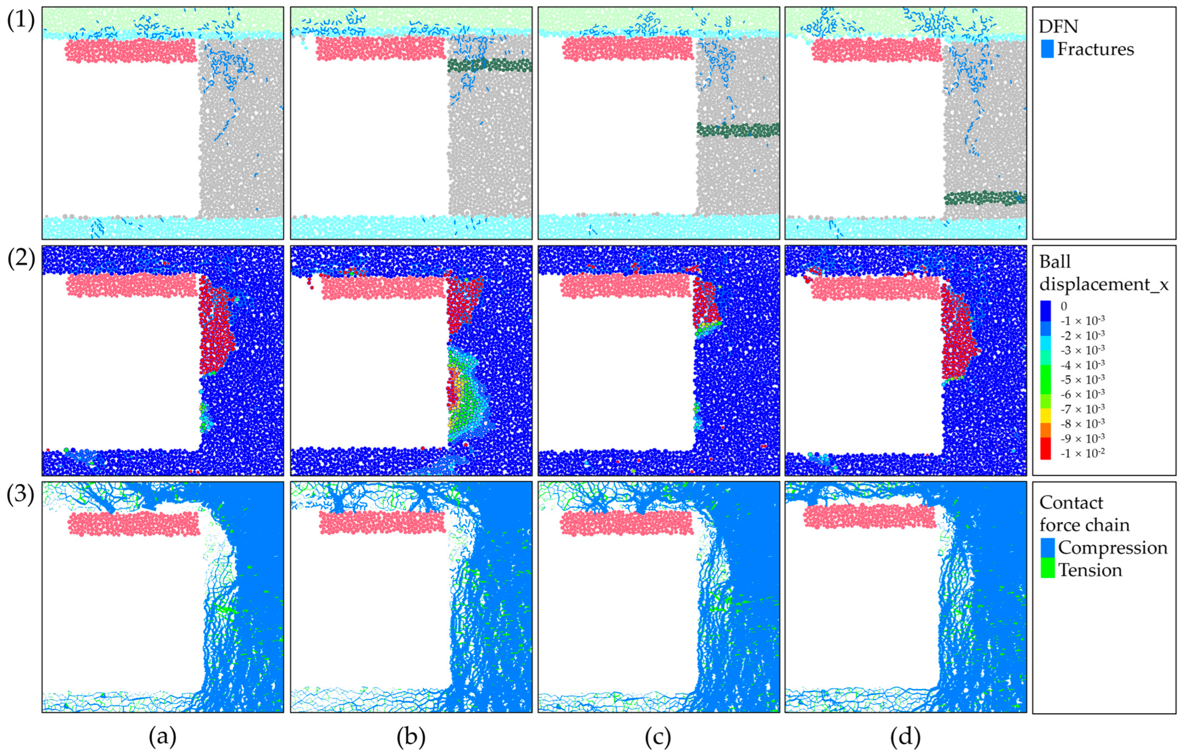
In order to analyze the influence of the working conditions with different locations of dirt bands on the failure of the coal walls in fully mechanized mining with a large mining height, four different dirt bands were established. The dirt band of the thick coal seam in the Xinyuan Huoxi Coalfield is mudstone, and the dirt band is designed and simulated as follows: Condition a: without dirt band; Condition b: upper dirt band; Condition c: middle dirt band; Condition d: lower dirt band.
A DEM numerical simulation was performed for coal wall failure under different dirt band conditions. It was found that the overburden migration and stress distribution were similar during advancement under different dirt band conditions, and that typical spalling occurred after advancement of 60 m. Therefore, the crack diagram, displacement cloud diagram, and force chain diagram under different dirt band conditions after advancement of 60 m were compared, and the comprehensive analysis is as follows:
Condition a: When the coal seam was complete without a dirt band, the coal seam suffered wedge-shaped failure due to tensile and shear stress. During the initial mining, the stress endured by the coal wall did not change significantly. Cracks occurred, but these were not connected. No spalling was observed. With the advancement of the working face, the peak stress gradually transferred in the direction of advancement. Due to the movement of overburden, the middle and upper coal seam began to suffer wall failure. When the advancement distance was 60 m, the depth of the failure boundary was 1.79 m; the height of wedge-shaped failure in the failure zone was 2.23 m; and there were oblique cracks in the plastic zone. The simulation results are shown in
Figure 7a;
Condition b: The dirt band was in the upper coal seam: During the initial mining, no cracks or spalling were observed. When the advancement distance reached 60 m, the depth of the failure boundary was 1.83 m; the height of the wedge-shaped failure in the failure zone was 0.87 m; and no failure occurred below the dirt band, and no oblique crack development was seen in the plastic zone. The simulation results are shown in
Figure 7b;
Condition c: The dirt band was in the middle coal seam: During the initial mining, the stress endured by the coal wall did not change significantly. Some micro-cracks occurred, but these were not connected. No spalling was observed. With the advancement of the working face, the failure zone was limited between the dirt band and the roof. When the advancement distance reached 60 m, the depth of failure boundary point was 1.86 m; the height of the wedge-shaped failure in the failure zone was 2.15 m; and a small number of oblique cracks developed in the plastic zone but did not exceed the mudstone dirt band. The simulation results are shown in
Figure 7c;
Condition d: The dirt band was in the lower coal seam: During the initial mining, the stress endured by the coal wall did not change significantly, and the internal tensile stress of coal wall was small. Cracks occurred, but these were not connected. No spalling was observed. When the advancement distance reached 60 m, the depth of failure boundary was 1.74 m; the height of wedge-shaped failure in the failure zone was 2.12 m; and oblique cracks developed in the plastic zone. The simulation results are shown in
Figure 7d.
Compared with occurrence without a dirt band, the changes in the position of the failure boundary points were small despite the different locations of the dirt band, which indicated that the dirt band significantly inhibited the crack development inside the coal seam. When the dirt band was in the upper coal wall, the coal broke due to pressure and was wedge-shaped under the action of dirt band; an elastomer was formed at the lower coal wall to generate tensile stress, the force transmission paths were fully preserved, the height of the wedge-shaped coal wall failure was significantly reduced; when the dirt band was in the middle of the coal seam, the crack development stopped above the dirt band, and the force transmission path in the plastic zone turned at the dirt band; when the dirt band was in the lower coal seam, the crack characteristics were similar to those when there was no dirt band. It is believed that the stability control of the upper coal wall should override the control of the lower part.
From the above law of coal seam failure, the following conclusions are reached: the No. 9 and No. 10 coal seams in the Huoxi Coalfield were mined as one, and the mudstone dirt band between the coal seams was usually in the upper coal seam, which reduced the height of spalling and was conductive to coal wall stability. Further, the stability control of the upper coal wall was the key to alleviating spalling in fully mechanized mining with a large mining height. During mining, guard plate should be set up to provide lateral pressure to the coal wall, thereby resisting instantaneous stress changes and alleviating the hazards of coal wall spalling caused by instantaneous stress changes.
4.2. Characteristics of Coal Wall Failure Under Different Advancements of Mining
Overburden migration is the root cause of coal wall spalling. After analysis of the characteristics of overburden caving through DEM numerical simulation, following a 50 m advancement of mining, roof fractures occurred. At this time, the roof was not caved, and cracks were generated near the coal wall because the tensile strength of coal reached the limit. This is the initial mining period, during which the coal wall was stable; as the advancement of mining reached 70 m, the roof began to break and was caved. Due to the strong strength and large thickness of the limestone roof in Huoxi Coalfield, the direct roof was a thin mudstone pseudo roof which easily formed a masonry-cantilever structure. The working face underwent hybrid cyclic pressure, with a caving interval of 20 m. The overburden migration is shown in
Figure 8.
Under the conditions of the original rock roof, the thick hard limestone had a long caving interval, and was prone to advanced breaking. With the torsion and the caving pressure of roof, the strength of the coal seam could no longer withstand the roof pressure. As a result, cracks and separation began to develop in the plastic zone, and were concentrated in the upper part. At the same time, wedge-shaped failure occurred in the failure zone. In case of the rotation and caving of key plates of the thick hard roof, the coal wall and roof generated concentrated stress. The roof failure zone was squeezed to break, and a slight falling collapse occurred with mining.
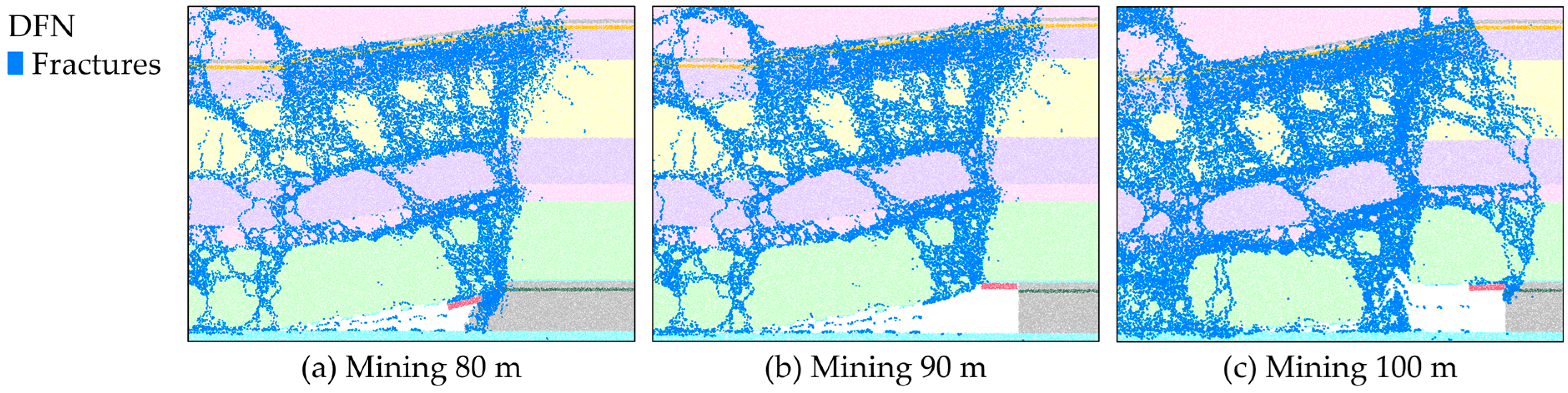
As can be seen from
Figure 8, spalling was related to the advanced breaking of roof, and was serious when the mining was advanced to 80 m and 100 m. When the mining was advanced to 80 m, initial caving pressure occurred in the roof. The depth of the failure boundary point was 4.13 m, and the height of the failure zone was the same as the mining height, accompanied by a roof subsidence of 3.65 m, as shown in
Figure 8a; when the mining was advanced to 100 m, there was cyclic pressure on the roof. The depth of the failure boundary point was 2.34 m, and the heigh of failure in the wedge-shaped failure zone was 3.69 m, with a roof sinking volume of 0.34 m, as shown in
Figure 8c.
In summary, spalling on the working face is concentrated when there is rotation and caving of the roof. At the same time, the roof sinks in large quantities. When caving is estimated, the protection level and working resistance of the hydraulic support for the working face should be increased. Furthermore, mining should be appropriately accelerated to avoid the falling before the support and the consequent spalling, thereby improving the stability of surrounding rock during fully mechanized mining with a large mining height.
4.3. Failure Characteristics of Coal Walls Under the Roof-Cutting Scheme
According to the simulation results of the original rock roof, it is believed that the rotation and caving of the key plates of thick hard roof are the main cause of the large-area spalling. In fully mechanized mining with a large mining height in Huoxi Coalfield, there was a large mining height, a large roof caving gap, large key blocks of masonry beam under the original rock roof conditions, and a cantilever-masonry beam structure. The violent pressure from the caving of cantilever beam and the rotation of the roof jointly caused the stress concentration of the coal seam.
In order to eliminate the hazard of long and overweight key blocks to the coal wall stability in fully mechanized mining with a large mining height in Huoxi Coalfield, a roof-cutting scheme was proposed. The blasting roof cutting can reduce the impact energy of the roof, reduce the size of key blocks, accelerate the formation of masonry beams, and reduce the stress concentration of rotation, being a fundamental measure to prevent the coal wall failure. On the basis of numerical simulation results, and by reference to actual engineering, the height of roof cutting was designed to be 23 m, and the key stratum of limestone was cut with an interval of 10 m. The schematic diagram of the overburden migration after roof cutting is shown in
Figure 9.
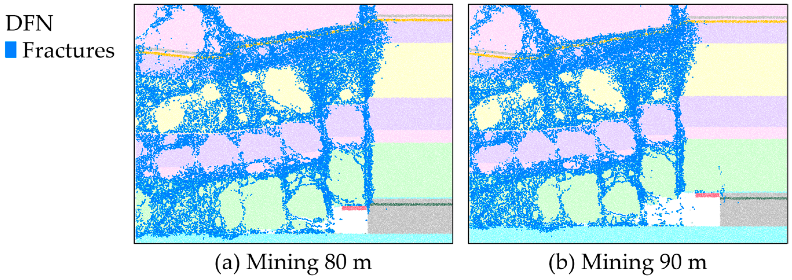
Figure 9a reflects the movement of the overburden in the working face under the condition of roof cutting when the working face is advanced by 80 m. It can be seen that the pre-splitting by the blasting of the working face roof effectively controls the development of fractures within the designed range. As the working face advances, the key rock blocks formed on the roof subside in the shape of small steps. Due to the effect of roof cutting, both the subsidence and rotation of the roof are significantly reduced, and the roof is well supported by the hydraulic support. When the working face is advanced by 90 m (
Figure 9b), due to the relatively small roof pressure, a short cantilever is formed. Even with the presence of pre-splitting, it does not collapse in advance and cause the support to be crushed.
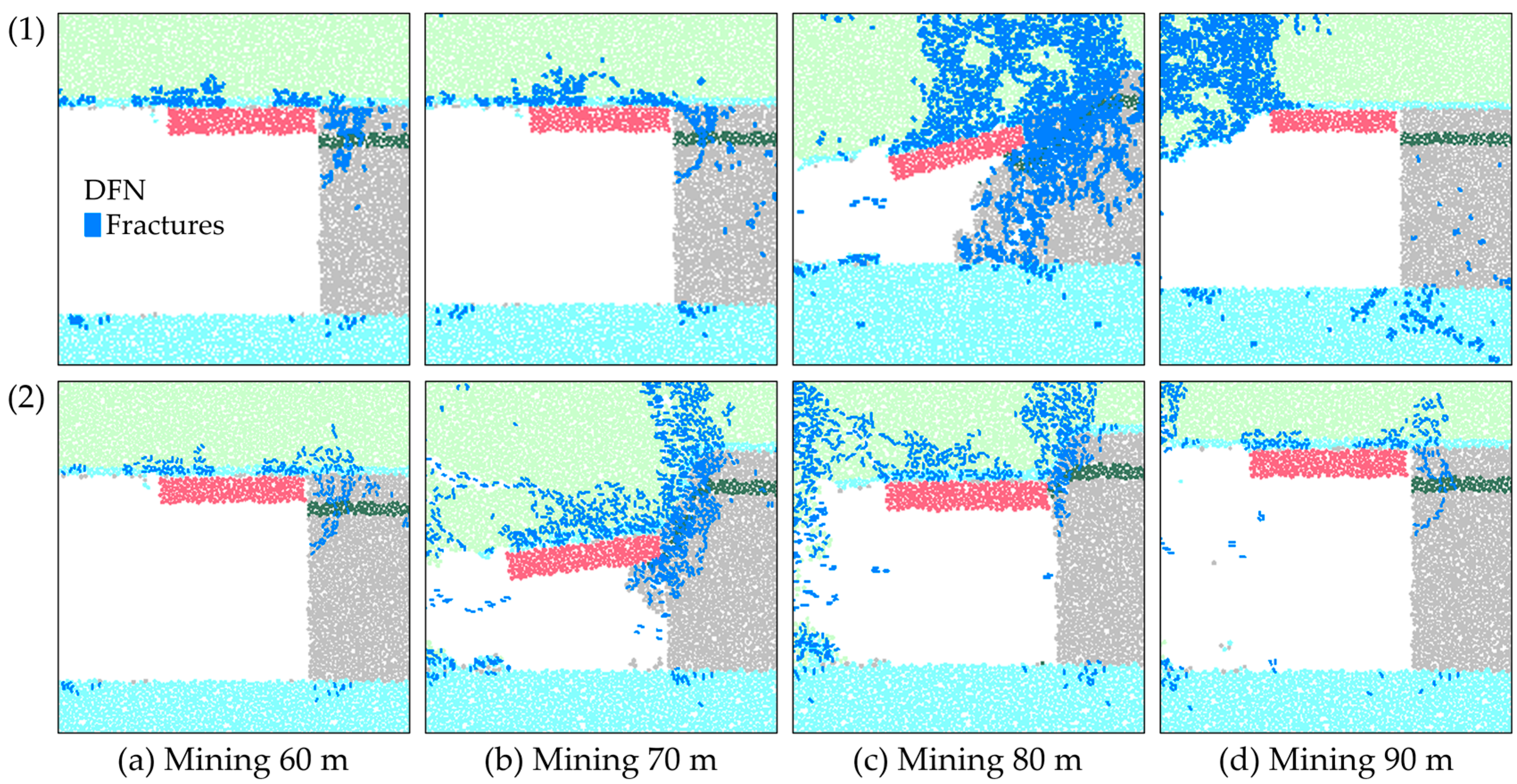
As shown in
Figure 10, by comparing the distribution of cracks in coal wall before and after roof cutting, it is concluded that after the cutting top, the initial rotation and caving of the roof occurred after mining advanced to 70 m. At this time, the spalling on the working face was the most serious, with a depth of 1.85 m at the failure boundary point and a height of 3.17 m at the wedge-shaped failure zone. Compared with the original rock roof conditions, the occurrence of large-area spalling at the working face was reduced, and no total coal wall failure occurred in the failure zone.
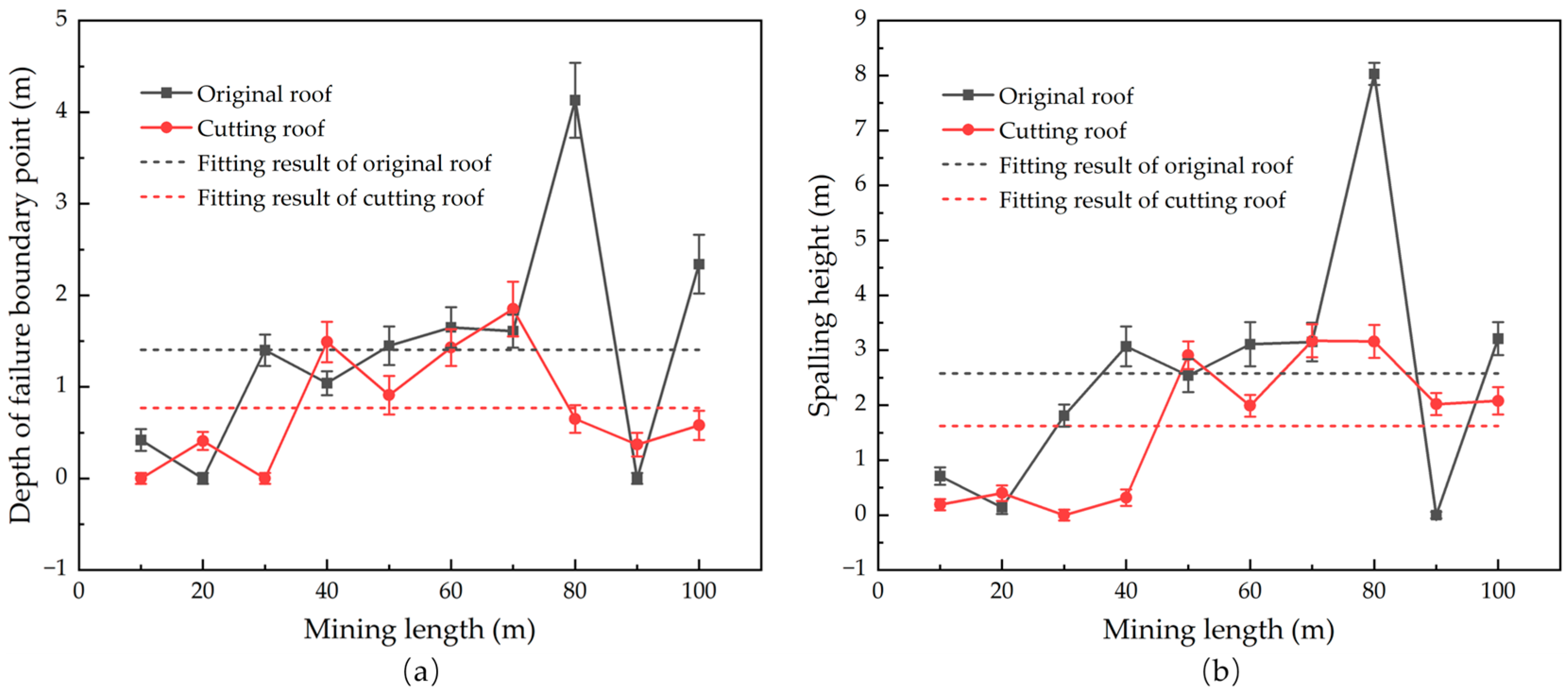
The depth of the failure boundary point and the state of the failure zone before and after roof cutting were analyzed. The average depth of the failure boundary point before roof cutting was 1.41 m, and it was 0.77 m after the roof cutting, decreasing by 45.4%. The depth curve of the failure boundary point before and after roof cutting is shown in
Figure 11a. The average height of the wedge-shaped spalling in the failure zone before roof cutting was 2.58 m, and it was 1.62 m after roof cutting, decreasing by 37.2%. The height curve of the failure zone before and after roof cutting is shown in
Figure 11b. It can be seen that advance roof cutting can effectively control spalling under thick hard-roof conditions during fully mechanized mining with a large mining height. This control effect is consistent with on-site research, detection and analysis.
5. Mechanism of Spalling in Fully Mechanized Mining with a Large Mining Height and the Control Schemes
5.1. Mechanism of Spalling on Coal Walls of Working Face
The caving of the roof during the advancement of the 8 m fully mechanized mining face in Huoxi Coalfield conforms to the “O-X” breaking law. Since the main roof of Huoxi Coalfield is a thick hard limestone roof with a long breaking step, it breaks in the goaf area after the ultimate bending strength is reached. The migration of overburden is characterized by the changes in the “cantilever-instability-hinge”.
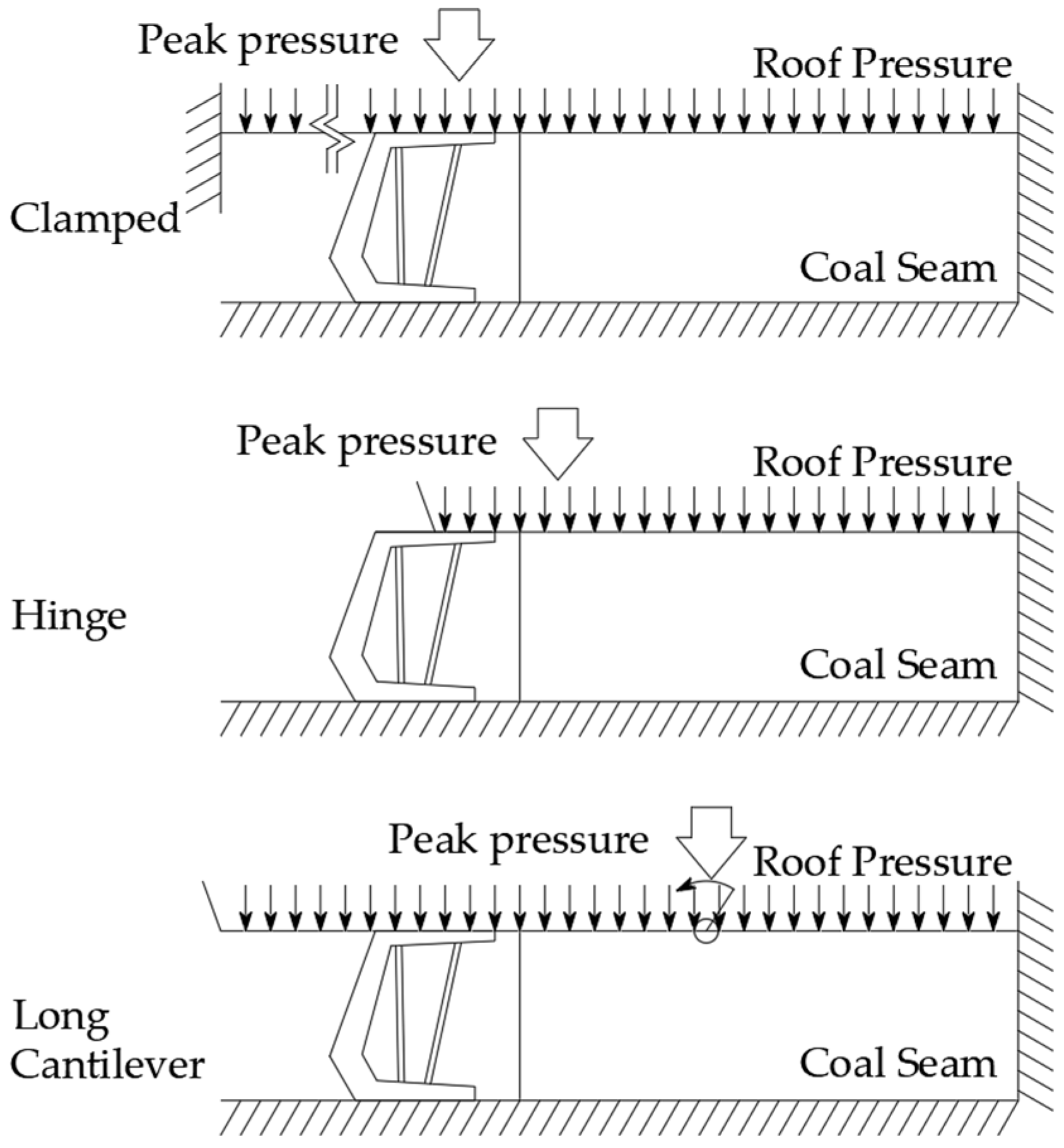
Figure 12 shows the roof load and the constraints when roof–coal seam–hydraulic support is balanced.
In the early stage of excavation, due to the stable strength of the thick hard roof and the hydraulic support, the mining site and the original rock structure form a fixed support on two sides to obtain the balance, and the front end of coal seam is not damaged since the peak roof pressure is behind the support; in fully mechanized mining with a large mining height, as the height of the caving zone increases, the range of activity of overburden formation is larger, which results in greater roof pressure and a forward shift in the peak stress of roof. Because the thick hard limestone roof in Huoxi Coalfield can still bear the pressure with the hydraulic support under roof pressure, a cantilever is formed during excavation. When the excavation length of working face reaches the critical value, the mine pressure is obvious, and cracks develop under the roof pressure. The roof is damaged to form a masonry beam structure, and the coal body at the front end is damaged.
After analysis of the principle of minimum potential energy of coal seam, it is concluded that when the coal wall is not constrained, the failure zone is the damage by tensile shear and splitting. If the cracks continue to develop, they will fall in the direction of the slop face, resulting in spalling. Due to the pressure of roof caving in mining with full mining height, a long rock cantilever forms on the roof, which easily causes deep and large spalling.
5.2. The Mechanism of the Influence of the Dirt Band on the Morphology of Spalling
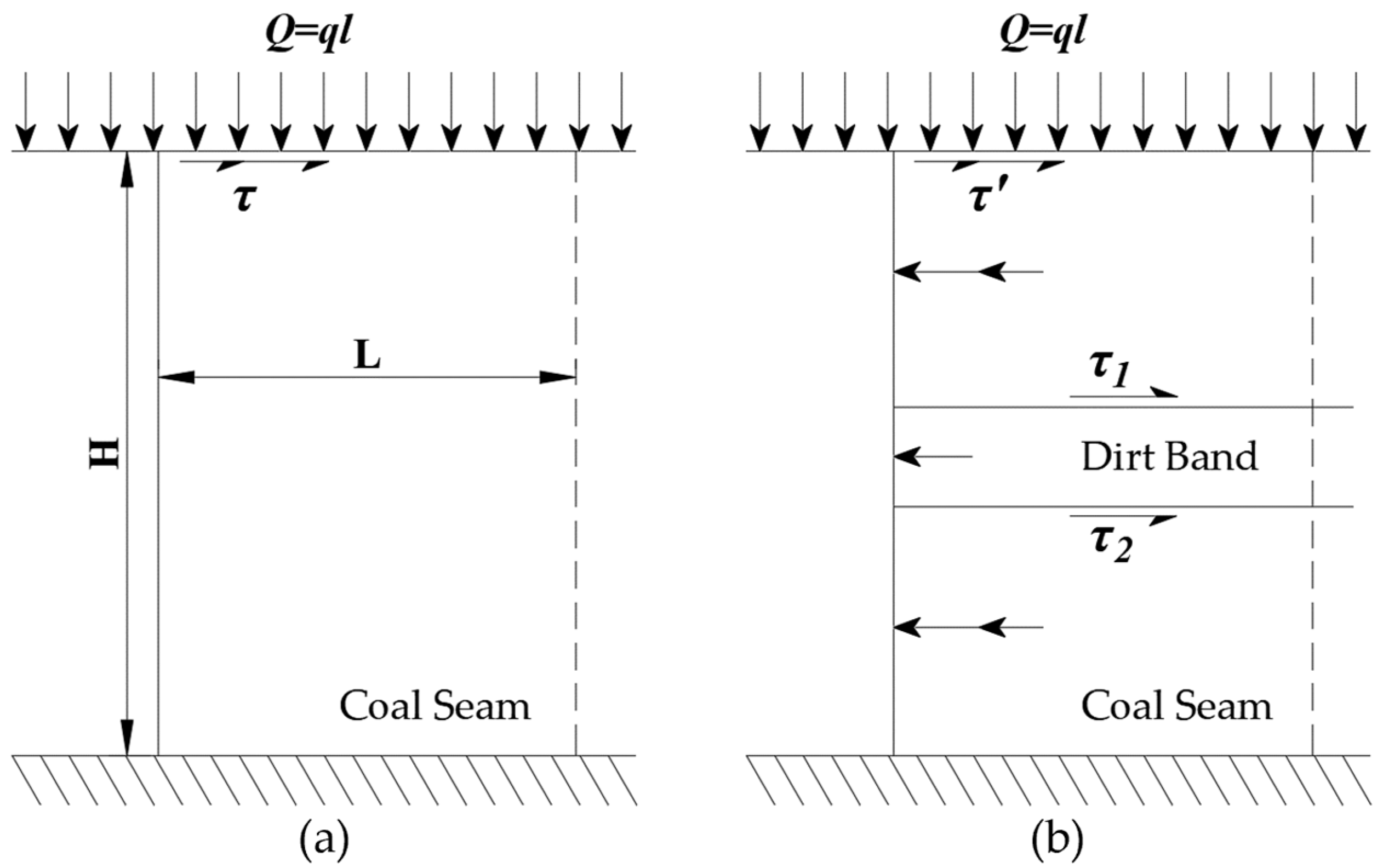
For a long time, it has been generally believed that the support design for multi-seam mining and ordinary mining is not different. However, according to the on-site conditions and simulation results, it is found that the dirt band of the coal seam inhibits spalling to a certain extent. In order to determine the mechanism of the influence of the dirt band on coal wall stability, the force analysis of the coal wall was carried out. The force state of the front end of the coal wall is shown in
Figure 13.
The front end of coal wall is simplified to an elastomer, and the analytic expression of the displacement component is derived from the principle of minimum potential energy as follows [
13]:
where
ux and
uy are the displacement functions of the coal wall in the horizontal and vertical directions;
x and
y are the coordinate variables, m;
E is the elastic modulus of coal seam, MPa;
v is Poisson’s ratio of the coal seam;
q is the positive stress of roof endured by the coal seam, MPa;
τ is the shear stress endured by the coal seam, MPa;
L is the depth of the front end of the coal wall, m; and
H is the mining height of the coal seam, m. The constitutive equation and geometric equation under plane strain conditions are introduced into Equations (1) and (2) to obtain the horizontal stress expression under roof pressure:
From Equation (3), it can be concluded that the coal seam is only related to Poisson’s ratio when under roof pressure. When Poisson’s ratio is small, horizontal tensile stress appears on the coal seam. Furthermore, as Poisson’s ratio continues to decrease, the tensile stress gradually increases.
Figure 13a presents the simplified model of the front-end coal wall under pressure when there is no dirt band in the coal seam. At this time, the coal wall is only affected by the roof pressure and its own mechanical properties. The equation reflects the displacement distribution of the coal wall at this moment. In the simplified model with a dirt band (
Figure 13b), due to the different Poisson’s ratios of the coal seam and the dirt bands, a horizontal stress gradient difference is formed between the coal seam and the dirt bands, thus generating shear stress between the coal seam and the parting.
Hard coal has a small Poisson’s ratio, and horizontal tensile stress occurs under the condition of roof pressure. Therefore, the failure of hard coal under roof pressure belongs to tensile–shear failure or splitting failure, which corresponds to the instability of the coal wall during the mining process. According to the analysis, the presence of the dirt band will change the stress–strain state of the coal wall. Since Poisson’s ratio of the dirt band is smaller than that of hard coal, under roof pressure, the horizontal strain of the dirt band is smaller than that of the coal seam. Due to the dirt band’s tensile strength being greater than coal seam, the dirt band can limit the horizontal displacement caused by the internal tensile stress of the coal wall, producing an anchoring effect, and effectively preventing the fractures from developing obliquely from the boundary points to the plastic zone. This discovery reveals the internal mechanical mechanism of the dirt band inhibiting the spalling of the production coal face. This inference is closely centered around the actual situation of the existence of partings in the fully mechanized mining faces with large mining heights in the Huoxi Coalfield, providing theoretical guidance for the rational use of dirt bands to control spalling in mining face.


