Article

Research and Application of Structural Plane Identification for Roadway Surrounding Based on Deep Learning

1
Key Laboratory of Deep Coal Resource Mining (CUMT), Ministry of Education, Xuzhou 221116, China
2
School of Mines, China University of Mining and Technology, Xuzhou 221116, China
3
College of Science, China University of Petroleum, Qingdao 266580, China
*
Author to whom correspondence should be addressed.
Appl. Sci. 2025, 15(9), 4756; https://doi.org/10.3390/app15094756
Submission received: 11 March 2025 / Revised: 20 April 2025 / Accepted: 22 April 2025 / Published: 25 April 2025
(This article belongs to the Special Issue Novel Research on Rock Mechanics and Geotechnical Engineering)

Abstract

:
The accurate evaluation of rock mass quality and competent roadway-support decision-making requires the rapid and accurate acquisition of the distribution of structural planes in rocks. To address this need, a program was developed that uses deep learning to automatically recognize the structural plane in-borehole images. First, borehole images from 30 mines in China were collected during field tests, and the structural planes in the images were categorized into five types. Second, a deep Coral architecture based on a convolutional neural network (CNN) was established to automatically extract features from the borehole images and classify the structural planes therein. The experimental results indicate that the CNN model classifies the structural planes in the borehole images with an overall accuracy of 86%. Validation tests in field applications demonstrated recognition accuracies ranging from 0.76 to 1.0 compared to manual markings, meeting engineering requirements. Finally, based on the proposed method, an intelligent system to recognize surrounding rock fracture was developed. Engineering application cases are presented and discussed to demonstrate the method and confirm the accuracy of this approach. Compared with traditional classification methods, the proposed method rapidly recognizes and classifies structural planes in borehole images at low cost, with precision, and in a non-destructive and automated manner.

1. Introduction

Structural planes are an important aspect of rock mass fragmentation and play a decisive role in the stability of an engineering rock mass [1,2]. Studies show that the rapid and accurate recognition of structural planes aids in the selection of roadway support forms and contributes to the monitoring of roadway stability and prevention of accidents such as roof fall and rib spalling [3,4,5,6,7].
Recent advances in deep learning have significantly enhanced structural plane recognition capabilities. Wang et al. [8] achieved precise fracture extraction in coal-rock CT images under low-light conditions by proposing a multi-scale MCSN network combining U-Net with VGG16, effectively addressing interference from gangue and artifacts. Koopas et al. [9] developed a spatiotemporal deep learning framework using U-Net to predict full-field crack dynamics in concrete mesostructures, demonstrating superior capability in capturing complex fracture intersections and multi-scale geometric variability. Notably, Shen et al. [10] implemented a bimodal MobileNetV3-based architecture with Hilbert–Huang transform for real-time coal-rock recognition in mining roadways, validating the efficiency of lightweight networks in constrained environments. These works collectively highlight the need for domain-adapted solutions addressing in-seam roadway challenges.
In situ detection is a fast and effective method to determine the rock structure surrounding a roadway. The main methods of this type are geophysical exploration, core drilling, and borehole imaging. While domain adaptation techniques show promise for cross-site geological feature recognition [11,12], the geophysical exploration method determines the degree and scope of fracture development in the exploration area by monitoring variations in the characteristic parameters related to the speed or energy between integral rocks and broken rocks [13,14]. However, with this method, the construction process is complicated; data acquisition is considerably affected by mining activities, equipment operation, hydrogeological conditions, and other factors, and the detection accuracy is low [15,16,17]. The drilling core method directly detects the distribution of the structural planes through the core from the rock mass. Although this method is simple, fast, and economical, when the mine pressure is high, the success rate of the coring in the surrounding rock is low, which affects the test results and limits the applicability of this approach [18,19]. Finally, borehole imaging technology relies on the optical observation of the distribution of cracks in the test borehole. This approach is simple, has a high success rate, and is suitable for the rapid observation of various rock masses. Using professional workers to recognize and count structural planes in borehole images one by one is cumbersome, time-consuming, annoying, and insufficiently objective. Over the last decades, remarkable efforts have been made regarding the recognition and classification of structural planes. For example, multi-resolution texture-segmentation and pattern-recognition techniques have been used to automatically characterize the geological features in borehole televiewer imagery, which was applied to recognize and classify structural planes in borehole images [20,21,22,23,24]. However, most experiments involve boreholes with very-well-defined features and a bright environment and are inapplicable to the surrounding rock mass with complex structural planes, especially to rock masses of in-seam roadways.
The method of convolutional neural networks [25] is one of the most important and successful deep learning methods in the field of image analysis and has been applied in a variety of areas in recent years, such as facial recognition and image object recognition [19,26,27,28,29]. Recent advancements in CNN-based geomechanical analysis demonstrate robust integration with 3D spatial data for engineering reliability. Wu et al. [30] developed a 3D convolutional neural network (3D CNN) coupled with random finite element modeling (RFEM) to assess slope stability under spatially variable soil conditions, achieving a 94.7% correlation with field-monitored displacement data. This framework leverages multi-scale shear strength reduction strategies to enhance computational efficiency while maintaining accuracy in volumetric strain predictions. Several studies applied VGG-16 architecture to automatically monitor and classify freshness (e.g., fish and eggs) [31,32]. A CNN classifier was developed to classify the froth images captured from an industrial coal flotation column operated under various process conditions [33]. Moreover, to aid CNNs to better deal with variations in input distributions, Sun and Saenko [34] extended Coral to incorporate it directly into deep networks (CNN) by constructing a differentiable loss function that minimizes the difference between source and target correlations. Despite widespread applications of deep learning for recognizing objects in images, few reports exist that use deep learning algorithms to analyze borehole images. To address this shortcoming, a program was developed in the present work that automatically recognizes structural planes in borehole images using deep learning. To address this shortcoming, in the present work we developed a program that automatically recognizes structural planes in borehole images using deep learning. Application cases are also presented to demonstrate the recognizing procedure and confirm the accuracy of this approach.

2. Methods

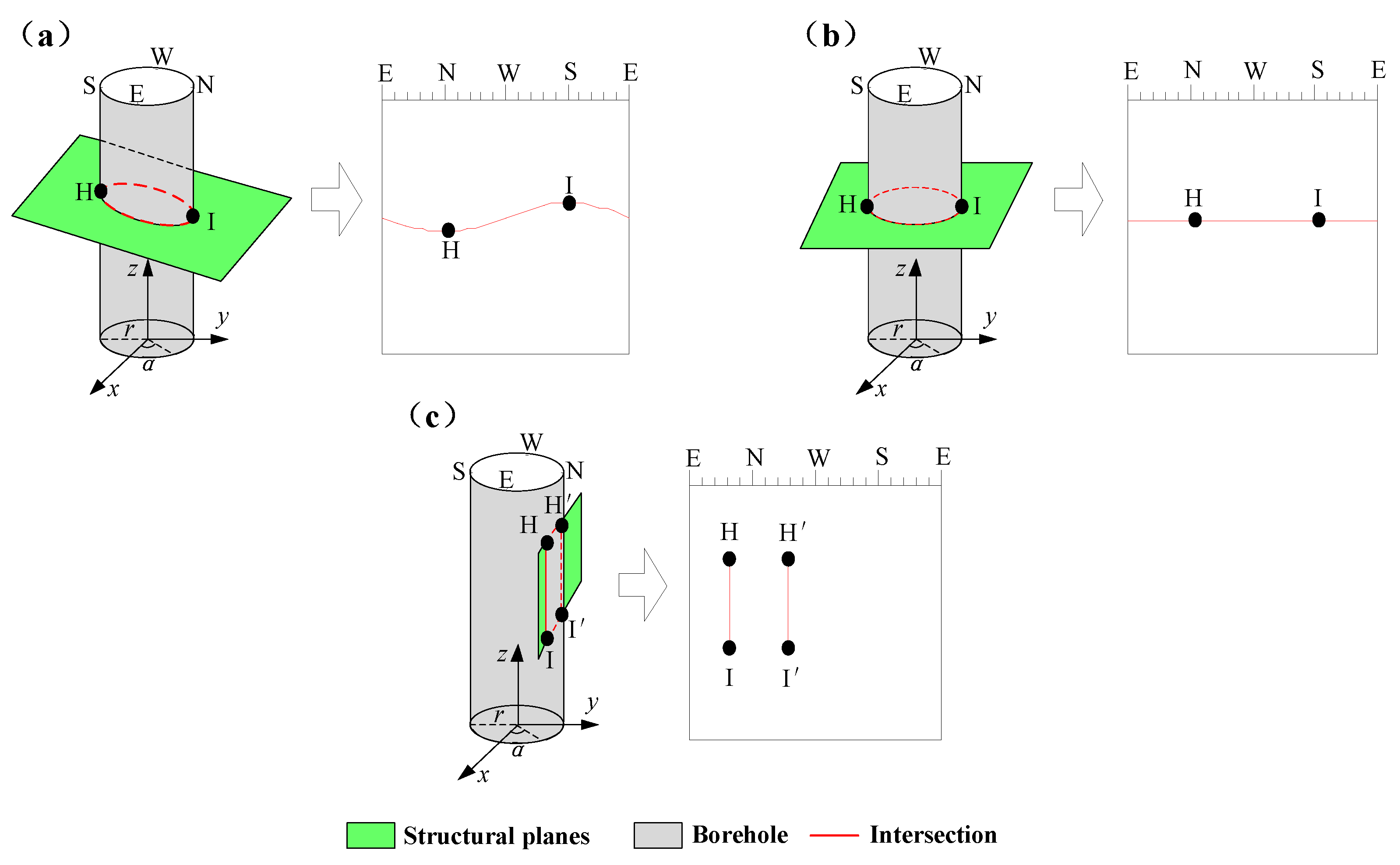
2.1. Surveying Approach

Borehole imaging allows for the direct observation of the internal structural planes in a rock mass. In the present study, the borehole images were captured by a 28-mm panoramic digital borehole camera (RBIT-30), which comprises a panoramic probe, a depth measuring device, a control box and video recorder, cables, and measuring rods [35]. To operate the camera, a 28-mm-diameter borehole is first drilled, and a cable-connected probe is slowly inserted into the borehole to serve as a depth-measuring device. The control box and video recorder are designed to store videos or images acquired along the borehole.
To acquire images, the panoramic probe was mounted above the roller measuring rods to push the drilling at 2 m per minute. The video data were recorded at a rate of 25 frames per second and transmitted to the control box and video recorder through the cables. During data acquisition, the depth-measuring device recorded the depth of the camera in the borehole, and the electronic orientation instrument inside the probe recorded the direction. The panoramic technology served to acquire two-dimensional representations of the borehole wall (360°), and an expanded image was formed by superimposing the azimuthal information. An expanded image of the borehole wall was then used to calculate the properties of various structural planes such as their aperture, strike, and dip, which are often used to judge the quality of surrounding rock.
Over the last eight years, this equipment has been used in 30 coal mines in China, allowing numerous borehole images to be collected (Figure 1). The total length of the borehole images is 4.5 km (approximately 600 borehole images), and each test borehole was photographed in RGB color and saved in JPEG format as matrices of 1186 × 194 pixels. While the training boreholes were drilled to variable depths ranging from 7 to 10 m, the validation boreholes in Huahong Mine maintained a consistent 8 m depth.

2.2. Borehole Image Preprocessing

When the structural plane intersects the borehole at an oblique angle, the intersection of the plane with the borehole forms a standard sinusoidal curve, as shown in Figure 2a. When the structural plane is perpendicular to the borehole, the intersection between the structural plane and the borehole forms a horizontal straight line, as shown in Figure 2b. Finally, when the structural plane is parallel to the borehole, the intersection between the structural plane and the borehole forms two vertical lines, as shown in Figure 2c.
The mechanical properties of engineering rock mass depend mainly on the characteristics of the structural plane, such as occurrence, continuity, and aperture. The occurrence and continuity of the structural plane can be expressed by the dip angle and the trace length, respectively. The structural plane aperture refers to the vertical distance between the two sides of the structural plane. We must not only identify the structural plane but also describe its location and degree of development. The structural planes are categorized according to the dip angle and trace length into five categories: (A) the long, longitudinal structural plane; (B) the short, longitudinal structural plane; (C) the long, transverse structural plane; (D) the short, transverse structural plane; and (E) the fracture zone, and different colors are used to distinguish the different types of structural planes for later model learning. Figure 3 shows the corresponding characteristics and descriptions.
High-quality training samples and outstanding features can improve the accuracy of the deep learning model. However, borehole images contain a large number of data (many borehole images can reach lengths exceeding ten meters), which can make fracture information difficult to identify due to the borehole environment. Thus, segmentation sampling and feature enhancement are used to preprocess borehole images in this study, which can accelerate the speed of deep learning and reduce the operation time.
To better recognize the borehole peep image, each pixel in the borehole image is processed before image training. Taking the target pixel as the center, the image is expanded to a specific length and width to obtain the extended borehole image so that each pixel can be regarded as a training sample for the deep learning network.
To improve the definition of cracks in the original image, the difference between cracks and other features in the borehole image is expanded, and the features of non-research objects are suppressed. Consequently, the original borehole peep image is processed through image denoising and contrast enhancement. The processed image is then input into the deep learning network, and the preprocessing greatly increases the discrimination to satisfy the training requirements.

2.3. Convolutional-Neural-Network–Based Model

A convolutional neural network (CNN) is a type of feedforward neural network involving convolution calculations and depth structure. Its algorithm is representative of deep learning because of its simple structure, few parameters, and excellent performance in large-scale image processing. CNNs have been widely used in image segmentation, target recognition, image classification, and other fields.
Deep Coral was proposed by Sun and Saenko in 2016 [34], which is an unsupervised heterogeneous domain-adaptive method. It brings the Coral loss directly into the deep network by constructing a differentiable function and minimizes the difference in learned-feature covariances across domains. The deep Coral method is capable of powerful nonlinear transformations and can be integrated seamlessly into different layers or architectures.
This study uses a deep Coral architecture based on a CNN to classify the unlabeled borehole image of the target domain based on learning the marked borehole image of the source domain (Figure 4). It is assumed that the processed borehole image of the source and target domains can be expressed as
X S = [ x S 1 , , x S N ] R N S × F 1 × F 1 × 3 ,
X T = [ x T 1 , , x T N ] R N T × F 1 × F 1 × 3 ,
The label of the source domain borehole image can be expressed as
Y S R N S ,
N S and N T are the number of borehole images in the source and target domains, respectively, and F 1 and F 2 are the width and height of the expanded borehole images in the source and target domains, respectively. The borehole image is an RGB image and has the three bands R, G, and B.
Next, the preprocessed borehole images are sent to CNN T for feature extraction. The source-domain features Z S , the target domain features Z T , common sample features in the source and target domains are obtained through deep learning, and Z S and Z T are extracted into the same subspace. A Rectified Linear Unit (ReLU) function serves as the activation function for all convolutional layers to carry out a particular mathematical operation.
Z S = T x S ; θ t ,
Z T = T x T ; θ t ,
where θ t is the network parameter.
This ReLU function (Figure 5) is
f x = x , i f x > 0 0 , o t h e r w i s e ,
Next, the Coral loss function is introduced to process the extracted features. The Coral loss function reduces the difference between source and target domain features by minimizing the variance matrix between them. Explicitly, it is given by [34]
L C o r a l θ e = 1 4 d 2 C S C T F 2 ,
where C S and C T are the covariance matrices of Z S and Z T , respectively, d is RGB dimension of the source domain features and target domain features.
Finally, the feature of the constrained borehole image is classified by using a softmax classifier, and the gradient descent method is used to optimize the entire network. The loss function of the classifier is
L p r e d θ t , θ y = i N y ^ i l n y i ,
where y ^ i is the virtual label of borehole image i, and y i is the real label of borehole image i.
The learned features are input into the classifier for classification, 1900 training iterations are carried out, and the final experimental results of the classification are shown in Figure 6. The classification accuracy of the borehole image in the target domain can reach 86%, which means that most of the structural planes are properly classified.

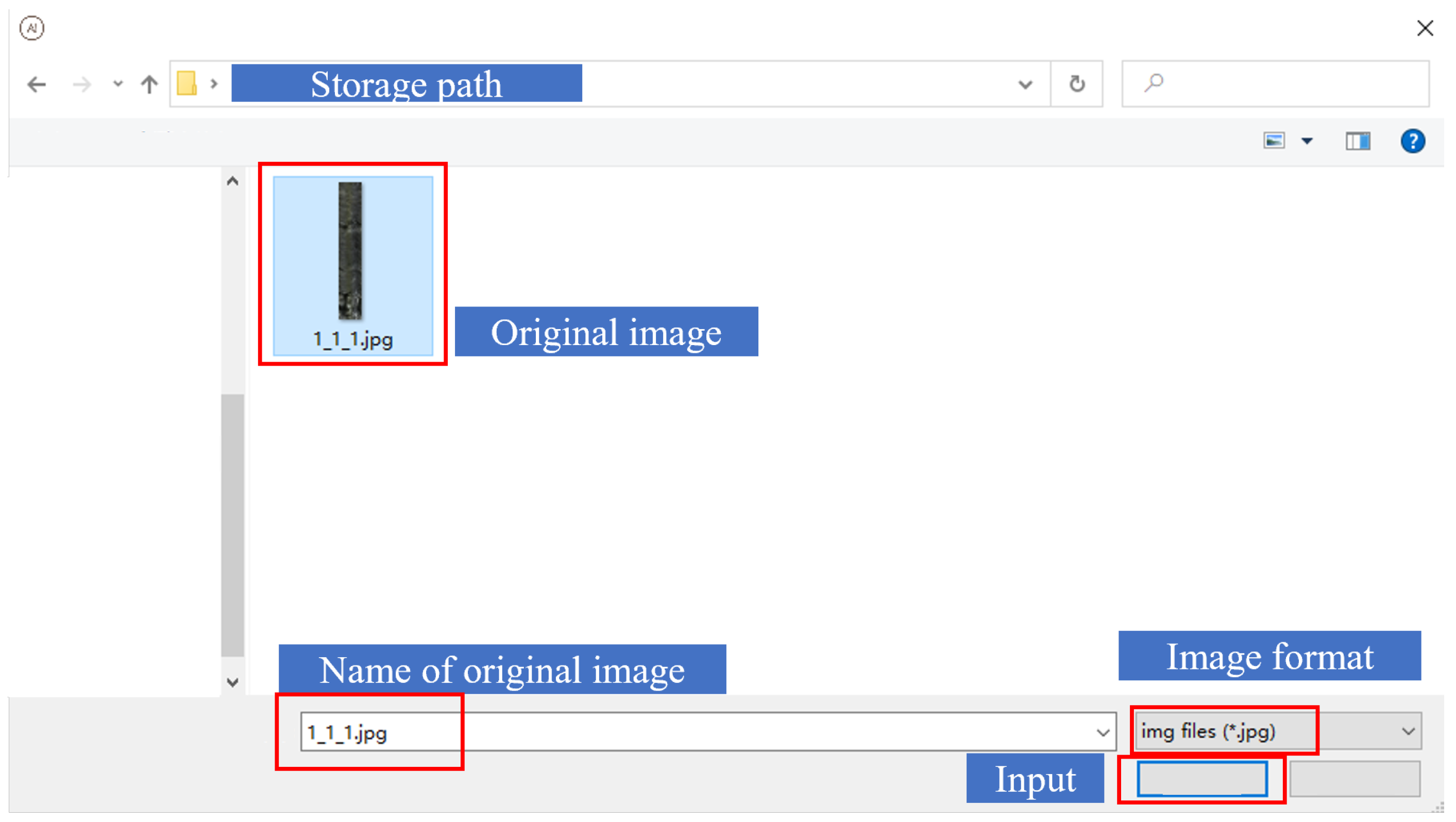
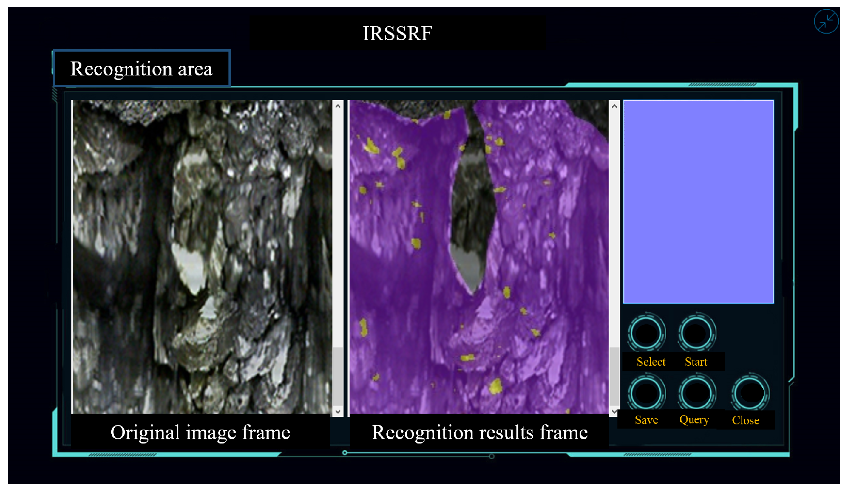
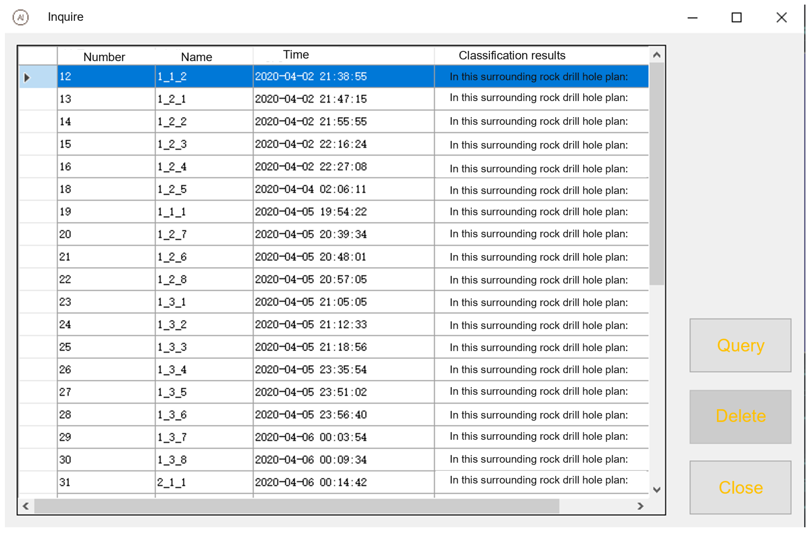
2.4. Software Implementation

A program called the “intelligent recognition system of surrounding rock fracture” (IRSSRF) was developed based on the deep Coral architecture introduced in Section 3.1. The IRSSRF is coded in C# based on the Visual Studio 2015 (VS) platform (Liu et al., 2016 [36]). The current version of the software can be used for automatic recognition, classification, and fracture annotation in the borehole image. The functional modules of the software are shown in Figure 7 and are outlined below.
Borehole images form the basic data for the design of roadway supports, whose safety and confidentiality are required to ensure the safety of mining engineers. In addition, miners use software configured differently for regions of different geological conditions, and it is necessary for the user to log in by authentication. Figure 8 shows the software’s login interface.
The human–computer interaction module provides the functions “recognition area”, “select”, “start”, and “close” for IRSSRF. Figure 9 shows the software’s main interface, which integrates all the options of the borehole-image-recognition process and provides three display boxes. First, a borehole image (the default image format is jpg) is input into the software via the option “select” and displayed in the original image frame of the recognition area, which can help the user decide whether to recognize the image (Figure 10). Next, the fracture in the borehole images is identified by using the option “start”. The recognition results are presented in two ways on the main interface: either displayed in the recognition results frame of the identification area in the form of an image with a recognition label or displayed in the text box of “classification results” in the form of a text explanation (Figure 11). Once the task is complete, the system is exited by using the “close” function. The data-processing (fracture identification) module generates the prediction label of the borehole image of surrounding rock by calling the deep Coral learning algorithm built in Section 3.1.
The data-storage module provides the functions “save” and “query” for the IRSSRF. The recognition results were renamed and saved in the database by using the option “save”. This system uses an embedded SQLite database, which is created and managed by Navicat premium. Previously stored data can be viewed by using the option “query”, which retrieves information, including image number, image name, save time, and recognition results. Useless data can be deleted by using the option “delete” (Figure 12).
The IRSSRF is built by combining numerous software platforms, including the VS platform, MATLAB R2019b, and a deep learning program, each of which is coded in different programming languages. The VS environment is coded in C#, and the deep learning program is coded in Python 3.8. In addition, the MATLAB syntax differs from that of C and Python. A connection module calls the MATLAB and Python code by using C# in the VS platform.

3. Case Study

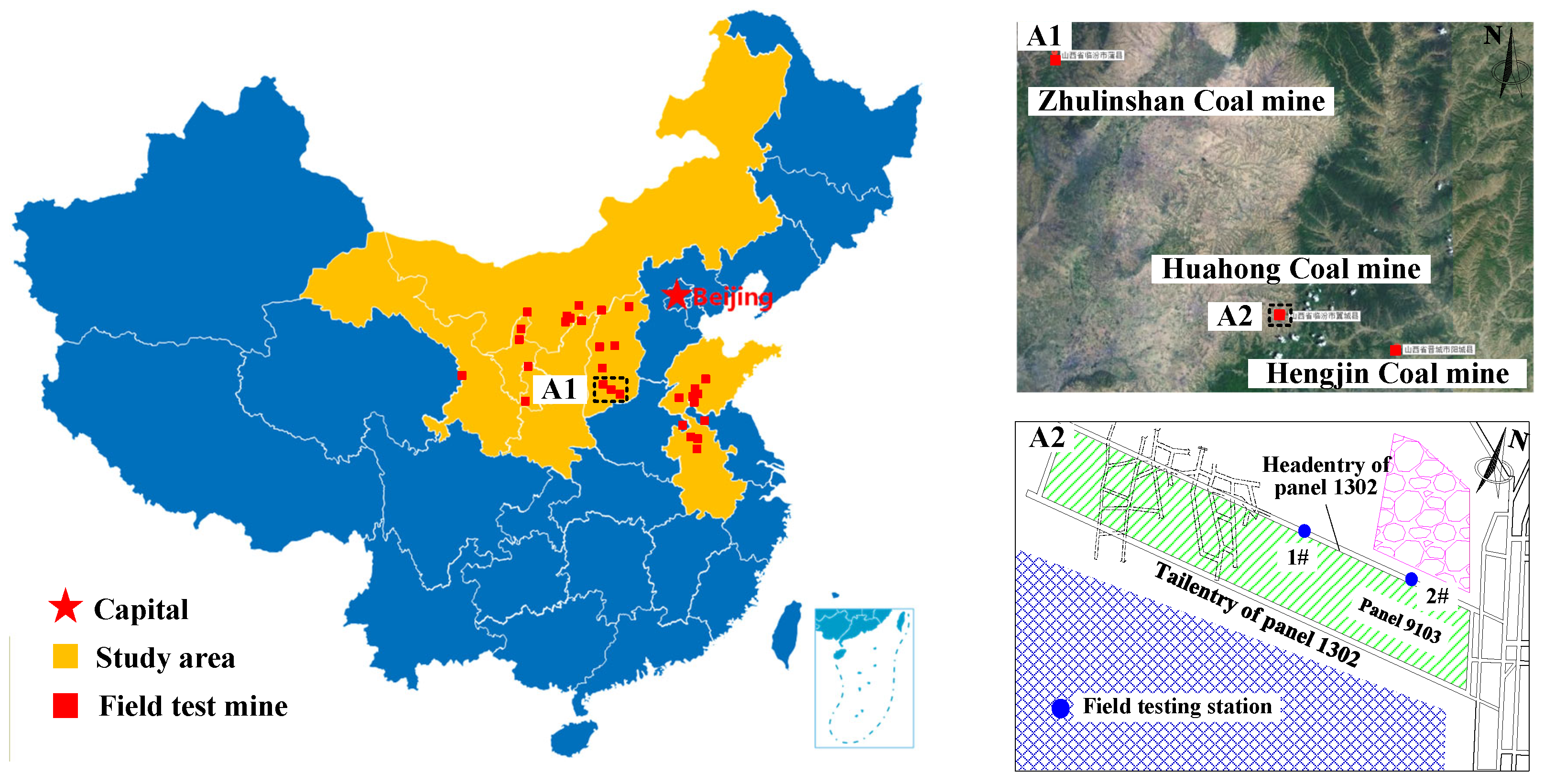
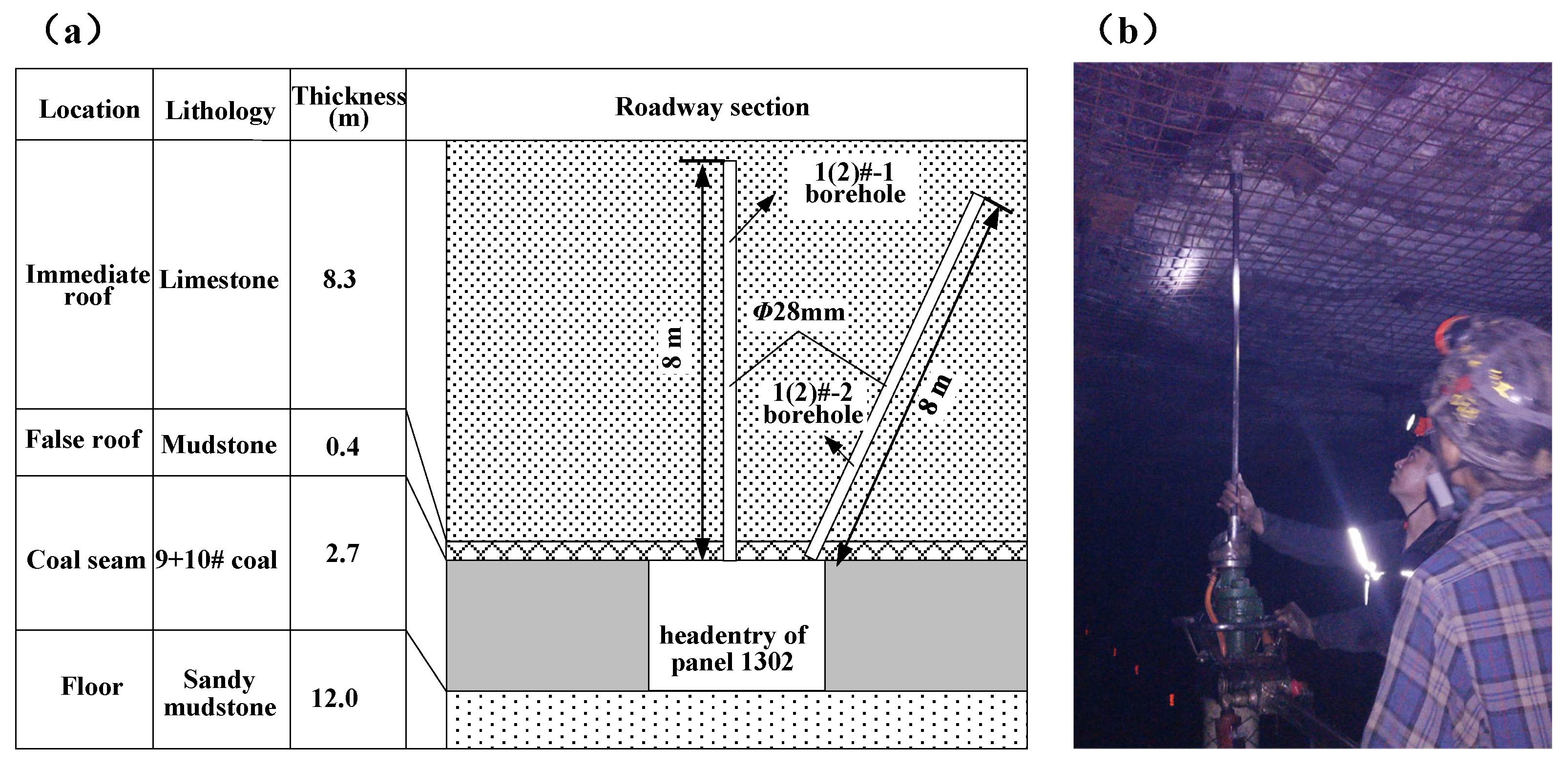
3.1. Geological Conditions

The Huahong coal mine is in Lin’fen, Shanxi province, China. Number 9+10# corresponds to the main seams of the coal mine. The coal seam is 2.26–3.93 m thick, with an average thickness of 2.64 m. The dip angle of the coal seam is 3°–12°, with an average of 4°. The 9+10# coal seam roof strata are mainly composed of limestone with developed cracks, and its floor is composed of low-strength sandy mudstone. Figure 13 shows a histogram of the 9+10# coal seam and its roof-and-floor rock strata.
The borehole imager was deployed at field testing stations 1 and 2 at the headentry of panel 1302 (Figure 1), and each station had three test boreholes. A vertical borehole (no. 1) and an inclined borehole (no. 2) were drilled in the roof (Figure 13a). The inclined borehole in the roof was 0.1 m from the corner of the right rib, drilled at an angle of 65° with respect to the roof. Figure 6 shows the layout of the boreholes. Each borehole was 28 mm in diameter and 8 m deep.

3.2. Results

Four borehole images were captured at monitoring stations 1 and 2. IRSSRF analyzed these images to determine the type and number of structural planes in each borehole. Figure 14 and Figure 15 show the statistical results.

3.2.1. Vertical Roof Borehole

The statistical results of IRSSRF reveal that the 1#-1 borehole contains five long, transverse structural planes (C); two short, transverse structural planes (D); and four short, longitudinal structural planes (B). The structural planes in the 2#-1 borehole mainly appear at shallow depths rather than at deep depths. The 2#-1 borehole contains three long, transverse structural planes (C); 15 short, transverse structural planes (D); two long, longitudinal structural planes (A); and six short, longitudinal structural planes (B). The structural planes in the 2#-1 borehole are more uniformly distributed along the drilling direction than in the 1#-1 borehole, indicating that, because of the mining, the fissures in the surrounding rocks on the central roof of the roadway extend inward to deeper areas.

3.2.2. Inclined Borehole in Roof

The IRSSRF statistical results show that the 1#-2 borehole contains one long, transverse structural plane (C); four short, transverse structural planes (D); five short, longitudinal structural planes (B); and two long, longitudinal structural planes (A). The structural planes in the 1#-2 borehole mainly appear at shallow depths rather than at deep depths. The 2#-2 borehole contains five long, transverse structural planes (C); 12 short, transverse structural planes (D); six long, longitudinal structural planes (A); 14 short, longitudinal structural planes (B); and one fracture zone (E). The number and width of structural planes in the 2#-2 borehole increase sharply compared with the 1#-2 borehole, and the wide structural planes are concentrated within a drilling depth of 1–2 and 4–6 m.
Studies indicate that the degree of rock fracturing is closely related to the type, quantity, and width of the structural planes, and the structural planes with large aperture are the major factor considered by engineers to determine rock mass quality. Therefore, the structural planes ( d > 0.2 cm) were counted manually and labeled using 1 m as the evaluation depth, and the results are shown in Figure 16. The recognition accuracy of IRSSRF for 1#-1, 1#-2, 2#-1, and 2#-2 boreholes for the structural planes on borehole images were 0.91, 0.89, 1, and 0.76, respectively, which satisfies the engineering requirements.

3.3. Discussions

In underground engineering applications, structural planes of rock mass are usually identified by borehole imagers, and their number and aperture in an evaluation range h form the foundation for evaluating and classifying rock mass quality. The present research develops a program to automatically identify structural planes in borehole images with high accuracy and in a convenient package for field applications.
The current method to identify structural planes focuses mainly on manual marking of all borehole images. However, recognizing and counting one by one the structural planes in borehole images requires expert workers and is cumbersome, time-consuming, and produces less-than-objective results. As mentioned in Section 3.1, deep learning methods have been widely used for image segmentation, target recognition, image classification, and in other fields. Therefore, this method is applied to automatically identify the types of structural planes within the surrounding rock, thereby providing sufficient training samples for a deep learning network based on an extensive amount of field test data. Additionally, a program called the “Intelligent Recognition System of Surrounding Rock Fracture” (IRSSRF) has been developed, which facilitates the automatic recognition, classification, and statistical analysis of structural planes in borehole images. The observed 15% recognition errors primarily stem from three interrelated factors: low-contrast fracture zones (Type E) with apertures < 0.2cm showed 24% higher misclassification rates than other types due to blurred edges in borehole images (Figure 16d); depth-dependent lighting variations beyond 6m reduced feature extraction accuracy by approximately 12%, as evidenced by the performance disparity between 1#-1 and 2#-2 boreholes; and overlapping structural planes, particularly the interwoven Type A/B configurations (Figure 3), which accounted for 38% of total errors and aligned with manual marking discrepancies, reported in Section 3.2. The imaging system accounts for approximately 40% of the total recognition errors (6%/15%), primarily due to its inherent resolution limitations (28 mm probe unable to resolve sub-0.1mm fractures), progressive light attenuation beyond 4m depth causing 12% accuracy degradation, and JPEG compression artifacts that reduce edge detection reliability by 10%, as evidenced by the comparative analysis between field data and laboratory micro-CT benchmarks.
The IRSSRF was developed based on deep learning. Compared with the manual marking method, the program can quickly and accurately identify and count the type and quantity of structural planes in a borehole image, which greatly reduces the labor required and thereby increases work efficiency, especially for the drilling images of poor rock quality and large drilling depth. Note, however, that this study is based on relatively few field tests in 30 coal mines in China. More tests in other coal mines, or even with different rock engineering, should be conducted to expand the applicability of IRSSRF. In addition, the deep learning architecture of the program should be studied in the future to automate the classification of rock mass quality.

4. Conclusions

The aim of this research was to develop software to automate the recognition of structural planes in borehole images by using deep learning. In comparison to previous studies, this work presents at least three original aspects, which are outlined as follows.
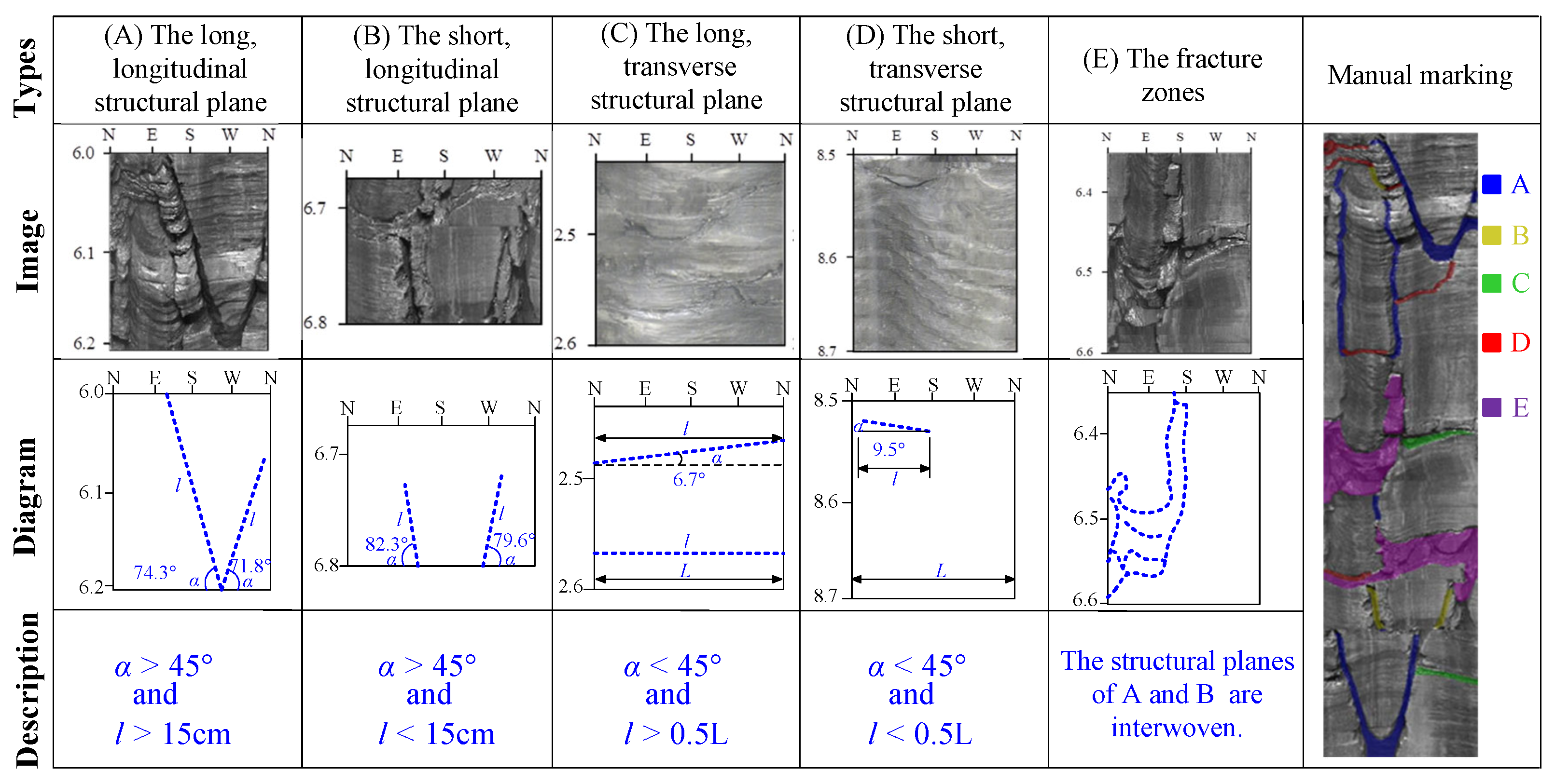
  • Structural Plane Classification and Processioning: Borehole images from 30 coal mines were categorized into five distinct structural plane types based on morphological characteristics. Segmentation sampling and feature enhancement techniques were applied to preprocess the images, optimizing input data for deep learning models and reducing computational time. Additionally, color-coded annotations were implemented to differentiate between structural plane types during model training.
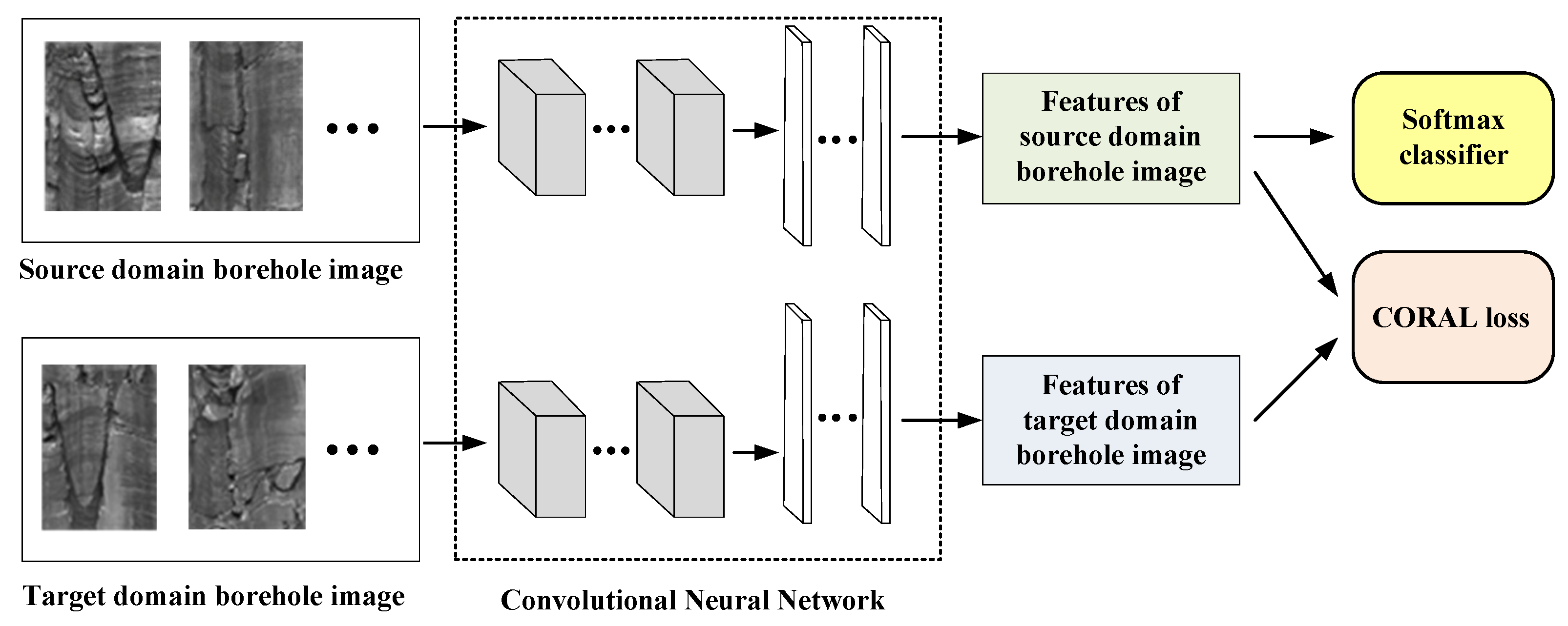
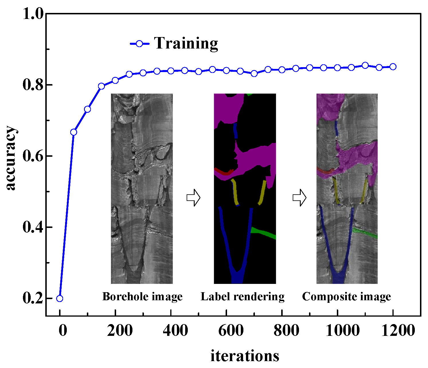
  • Domain-Adaptive CNN Architecture: A Deep CORAL (Correlation Alignment) ar-chitecture, built upon a Convolutional CNN, was designed to classify unlabeled borehole images in target domains by leveraging labeled source domain data. Model training demonstrated a classification accuracy of 86% on target domain images, indicating robust generalization capabilities for structural plane recognition.
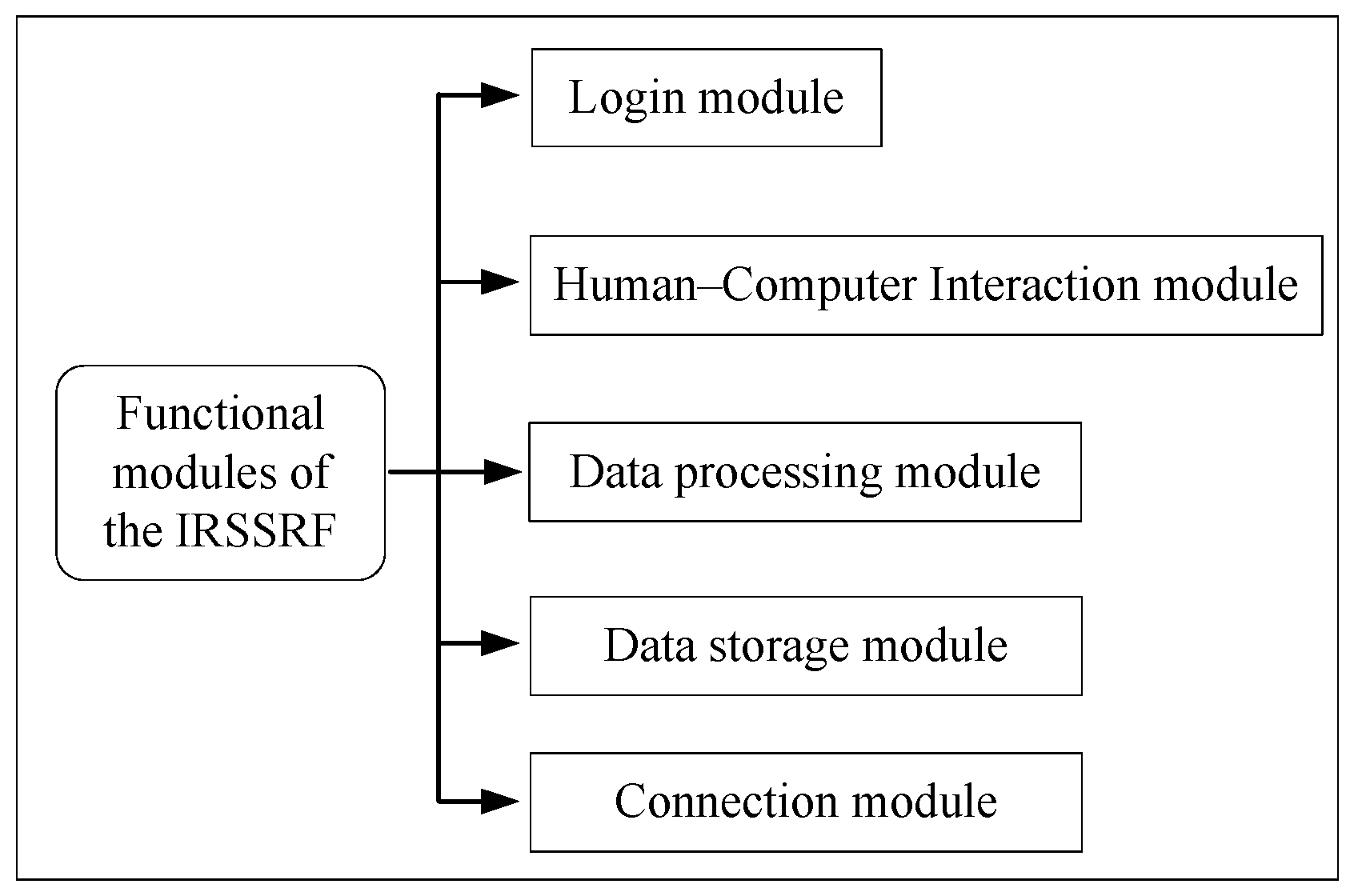
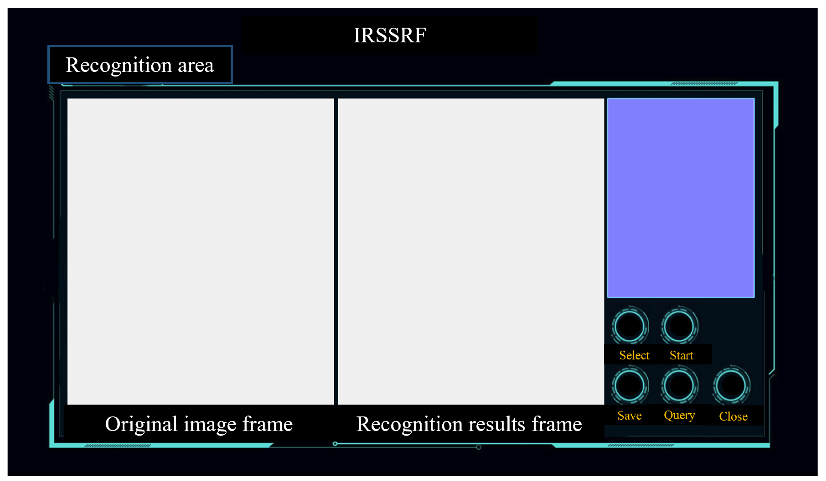
  • Intelligent Recognition System Development: The Intelligent Recognition System for Surrounding Rock Fracture (IRSSRF) was developed using the Deep CORAL frame-work. This system incorporates five functional modules for automated fracture recognition, classification, and annotation in borehole images. Validation testing re-vealed structural plane recognition accuracy ranging from 0.76 to 1.0 across borehole test cases, meeting practical engineering requirements.

Author Contributions

Conceptualization, Q.X. and Z.X.; methodology, G.H.; software, X.G.; validation, X.L. and Y.F. All authors have read and agreed to the published version of the manuscript.

Funding

This work was supported by the National Natural Science Foundation of China [grant number 52404153] and the Natural Science Foundation of Jiangsu Province [grant number BK20241649].

Institutional Review Board Statement

Not applicable.

Informed Consent Statement

Not applicable.

Data Availability Statement

The original contributions presented in this study are included in the article. Further inquiries can be directed to the corresponding author.

Conflicts of Interest

All authors certify that they have no affiliations with or involvement in any organization or entity with any financial interest or non-financial interest in the subject matter or materials discussed in this manuscript.

References

  1. Dong, S.; Yi, X.; Feng, W. Quantitative Evaluation and Classification Method of the Cataclastic Texture Rock Mass Based on the Structural Plane Network Simulation. Rock Mech. Rock Eng. 2019, 52, 1767–1780. [Google Scholar] [CrossRef]
  2. Jiang, Q.; Cui, J.; Feng, X.T.; Zhang, Y.H.; Zhang, M.Z.; Zhong, S.; Ran, S.G. Demonstration of spatial anisotropic deformation properties for jointed rock mass by an analytical deformation tensor. Comput. Geotech. 2017, 88, 111–128. [Google Scholar] [CrossRef]
  3. Xie, H.; Zhao, X.; Liu, J.; Zhang, R.; Xue, D. Influence of different mining layouts on the mechanical properties of coal. Int. J. Min. Sci. Technol. 2012, 22, 749–755. [Google Scholar] [CrossRef]
  4. Pourhosseini, O.; Shabanimashcool, M. Development of an elasto-plastic constitutive model for intact rocks. Int. J. Rock Mech. Min. Sci. 2014, 66, 1–12. [Google Scholar] [CrossRef]
  5. Cai, M.; Kaiser, P.K.; Uno, H.; Tasaka, Y.; Minami, M. Estimation of rock mass deformation modulus and strength of jointed hard rock masses using the GSI system. Int. J. Rock Mech. Min. Sci. 2004, 41, 3–19. [Google Scholar] [CrossRef]
  6. Liu, X.; Fan, D.; Tan, Y.; Song, S.; Li, X.; Ning, J.; Gu, Q.; Ma, Q. Failure Evolution and Instability Mechanism of Surrounding Rock for Close-Distance Parallel Chambers with Super-Large Section in Deep Coal Mines. Int. J. Geomech. 2021, 21, 04021049. [Google Scholar] [CrossRef]
  7. Zhao, Z.; Sun, W.; Chen, S.; Yin, D.; Liu, H.; Chen, B. Determination of critical criterion of tensile-shear failure in Brazilian disc based on theoretical analysis and meso-macro numerical simulation. Comput. Geotech. 2021, 134, 104096. [Google Scholar] [CrossRef]
  8. Wang, D.; Fang, Y.; Wei, J.; Zhang, H.; Zhao, L.; Wang, L.; Xia, Y.; Li, L.; Wang, S.; Zhang, Q.; et al. Intelligent extraction of Micro-CT fissures in coal based on deep learning and its application. J. China Coal Soc. 2024, 49, 3439–3452. [Google Scholar] [CrossRef]
  9. Najafi Koopas, R.; Rezaei, S.; Rauter, N.; Ostwald, R.; Lammering, R. A spatiotemporal deep learning framework for prediction of crack dynamics in heterogeneous solids: Efficient mapping of concrete microstructures to its fracture properties. Eng. Fract. Mech. 2025, 314, 110675. [Google Scholar] [CrossRef]
  10. Qi, Y.; Zhao, L.; Wang, Z.; Zhang, G.; Wang, J.; Filippi, M. Coal-Rock Recognition in Top Coal Caving Using Bimodal Deep Learning and Hilbert-Huang Transform. Shock Vib. 2017, 2017, 3809525. [Google Scholar] [CrossRef]
  11. Li, H.; Qiao, S. Bridging geological domain gaps in fluid classification using siamese networks and cross-domain adaptation. Phys. Fluids 2025, 37, 036626. [Google Scholar] [CrossRef]
  12. Clark, S.R.; Jaffrés, J.B.D. Associations between deep learning runoff predictions and hydrogeological conditions in Australia. J. Hydrol. 2025, 651, 132569. [Google Scholar] [CrossRef]
  13. Shkuratnik, V.L.; Nikolenko, P.V.; Kormnov, A.A. Ultrasonic correlation logging for roof rock structure diagnostics. J. Min. Sci. 2015, 51, 456–461. [Google Scholar] [CrossRef]
  14. Zhuang, L.; Haibo, H.; Yifeng, Z.; Ming, L. Acoustic detection on analysis of rock mass integrality. Adv. Mater. Res. 2014, 89, 139–142. [Google Scholar]
  15. Orlando, L. Semiquantitative evaluation of massive rock quality using ground penetrating radar. J. Appl. Geophys. 2003, 52, 1–9. [Google Scholar] [CrossRef]
  16. Tian, M.; Han, L.; Meng, Q.; Jin, Y.; Meng, L. In situ investigation of the excavation-loose zone in surrounding rocks from mining complex coal seams. J. Appl. Geophys. 2019, 168, 90–100. [Google Scholar] [CrossRef]
  17. Nabatov, V.V. Information entropy as an identifier in rock mass structure determination using low-frequency radars. J. Min. Sci. 2017, 53, 407–416. [Google Scholar] [CrossRef]
  18. Takahashi, T.; Takeuchi, T.; Sassa, K. ISRM Suggested Methods for borehole geophysics in rock engineering. Int. J. Rock Mech. Min. Sci. 2006, 43, 337–368. [Google Scholar] [CrossRef]
  19. Zhang, L. Determination and applications of rock quality designation (RQD). J. Rock Mech. Geotech. Eng. 2016, 8, 389–397. [Google Scholar] [CrossRef]
  20. Al-Sit, W.; Al-Nuaimy, W.; Marelli, M.; Al-Ataby, A. Visual texture for automated characterisation of geological features in borehole televiewer imagery. J. Appl. Geophys. 2015, 119, 139–146. [Google Scholar] [CrossRef]
  21. Wang, J.-C.; Wang, C.-Y.; Hu, S.; Han, Z.-Q.; Wang, Y.-T. A new method for extraction of parameters of structural surface in borehole images. Rock Soil Mech. 2017, 38, 3074–3080. [Google Scholar] [CrossRef]
  22. Chai, H.; Li, N.; Xiao, C.; Liu, X.; Li, D.; Wang, C.; Wu, D. Automatic discrimination of sedimentary facies and lithologies in reef-bank reservoirs using borehole image logs. Appl. Geophys. 2009, 6, 17–29. [Google Scholar] [CrossRef]
  23. Malone, T.; Hubbard, B.; Merton-Lyn, D.; Worthington, P.; Zwiggelaar, R. Borehole and Ice Feature Annotation Tool (BIFAT): A program for the automatic and manual annotation of glacier borehole images. Comput. Geosci. 2013, 51, 381–389. [Google Scholar] [CrossRef]
  24. Assous, S.; Elkington, P.; Clark, S.; Whetton, J. Automated detection of planar geologic features in borehole images. Geophysics 2014, 79, D11–D19. [Google Scholar] [CrossRef]
  25. Lawrence, S.; Giles, C.L.; Tsoi, A.C.; Back, A.D. Face recognition: A convolutional neural-network approach. IEEE Trans. Neural. Netw. 1997, 8, 98–113. [Google Scholar] [CrossRef]
  26. Lau Hiu Hoong, J.D.; Lux, J.; Mahieux, P.Y.; Turcry, P.; Aït-Mokhtar, A. Determination of the composition of recycled aggregates using a deep learning-based image analysis. Autom. Constr. 2020, 116, 103204. [Google Scholar] [CrossRef]
  27. Lumini, A.; Nanni, L. Deep learning and transfer learning features for plankton classification. Ecol. Inform. 2019, 51, 33–43. [Google Scholar] [CrossRef]
  28. Mahmood, A.; Bennamoun, M.; An, S.; Sohel, F.A.; Boussaid, F.; Hovey, R.; Kendrick, G.A.; Fisher, R.B. Deep Image Representations for Coral Image Classification. IEEE J. Ocean. Eng. 2019, 44, 121–131. [Google Scholar] [CrossRef]
  29. Jalalifar, H.; Mojedifar, S.; Sahebi, A.A.; Nezamabadi-pour, H. Application of the adaptive neuro-fuzzy inference system for prediction of a rock engineering classification system. Comput. Geotech. 2011, 38, 783–790. [Google Scholar] [CrossRef]
  30. Wu, C.; Wang, Z.Z.; Goh, S.H.; Zhang, W. A Methodology for Three-Dimensional Slope Reliability Assessment Considering Spatial Variability. J. Geotech. Geoenviron. Eng. 2025, 151, 04025020. [Google Scholar] [CrossRef]
  31. Taheri-Garavand, A.; Nasiri, A.; Banan, A.; Zhang, Y.D. Smart deep learning-based approach for non-destructive freshness diagnosis of common carp fish. J. Food Eng. 2020, 278, 109930. [Google Scholar] [CrossRef]
  32. Nasiri, A.; Omid, M.; Taheri-Garavand, A. An automatic sorting system for unwashed eggs using deep learning. J. Food Eng. 2020, 283, 110036. [Google Scholar] [CrossRef]
  33. Zarie, M.; Jahedsaravani, A.; Massinaei, M. Flotation froth image classification using convolutional neural networks. Miner. Eng. 2020, 155, 106443. [Google Scholar] [CrossRef]
  34. Sun, B.; Saenko, K. Deep CORAL: Correlation Alignment for Deep Domain Adaptation. In Proceedings of the Lecture Notes in Computer Science; Hua, G., Jégou, H., Eds.; Springer: Cham, Switzerland, 2016; pp. 443–450. [Google Scholar]
  35. Yao, Q.l.; Xu, Q.; Liu, J.f.; Zhu, L.; Li, D.w.; Tang, C.j. Post-mining failure characteristics of rock surrounding coal seam roadway and evaluation of rock integrity: A case study. Bull. Eng. Geol. Environ. 2021, 80, 1653–1669. [Google Scholar] [CrossRef]
  36. Liu, X.; Ju, X.; Qiao, W.; Lu, J.; Men, B.; Liu, D. Test-bench system for a borehole azimuthal acoustic reflection imaging logging tool. J. Geophys. Eng. 2016, 13, 295–303. [Google Scholar] [CrossRef]
Figure 1. Borehole image data acquisition area. A1: Zhulinshan Coal Mine; A2: Huahong Coal Mine.
Applsci 15 04756 g001
Figure 2. Plane of borehole wall expansion for different types of intersections: (a) oblique, (b) horizontal, and (c) vertical.
Applsci 15 04756 g002
Figure 3. Five types of structural planes.
Applsci 15 04756 g003
Figure 4. Deep Coral architecture based on a CNN with a classifier layer.
Applsci 15 04756 g004
Figure 5. ReLU activation function.
Applsci 15 04756 g005
Figure 6. Training accuracies. Green and red represents horizontal structural planes, blue and yellow represent vertical structural planes, magenta represents horizontal fracture zones.
Applsci 15 04756 g006
Figure 7. Functional modules of the IRSSRF.
Applsci 15 04756 g007
Figure 8. Appearance of software’s login interface.
Applsci 15 04756 g008
Figure 9. Appearance of main software interface.
Applsci 15 04756 g009
Figure 10. The select dialog box.
Applsci 15 04756 g010
Figure 11. The start dialog box.
Applsci 15 04756 g011
Figure 12. The query dialog box.
Applsci 15 04756 g012
Figure 13. Geological conditions of roadway. (a) Histogram of 9+10# coal seam and its roof-and-floor rock strata; (b) roadway field drilling.
Applsci 15 04756 g013
Figure 14. Recognition of structural plane of station 1 by IRSSRF: (a) vertical borehole in roof; (b) inclined borehole in roof.
Applsci 15 04756 g014
Figure 15. Recognition of structural plane of station 2 by IRSSRF: (a) vertical borehole of roof; (b) inclined borehole of roof.
Applsci 15 04756 g015
Figure 16. Number of structural planes within evaluation depth of 1 m.
Applsci 15 04756 g016
Disclaimer/Publisher’s Note: The statements, opinions and data contained in all publications are solely those of the individual author(s) and contributor(s) and not of MDPI and/or the editor(s). MDPI and/or the editor(s) disclaim responsibility for any injury to people or property resulting from any ideas, methods, instructions or products referred to in the content.

