

3D-Printed Lightweight Foamed Concrete with Dispersed Reinforcement


Abstract
1. Introduction
1.1. Fibers in 3D Printing
1.2. Foam Concrete in 3D Printing
1.3. Fiber Reinforced Foam Structures
2. Materials and Methods
2.1. Materials
2.2. Designing the Mixtures
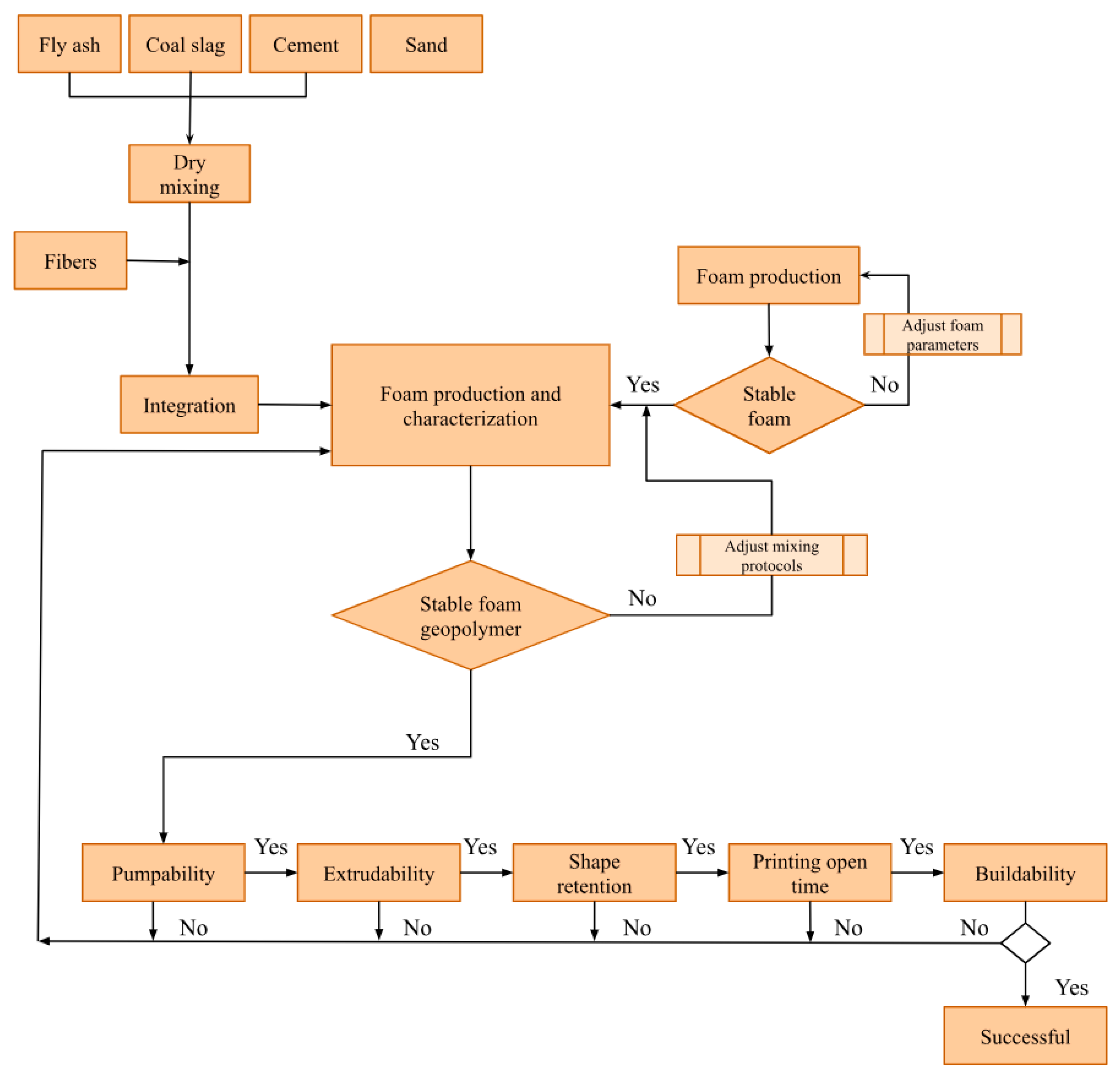
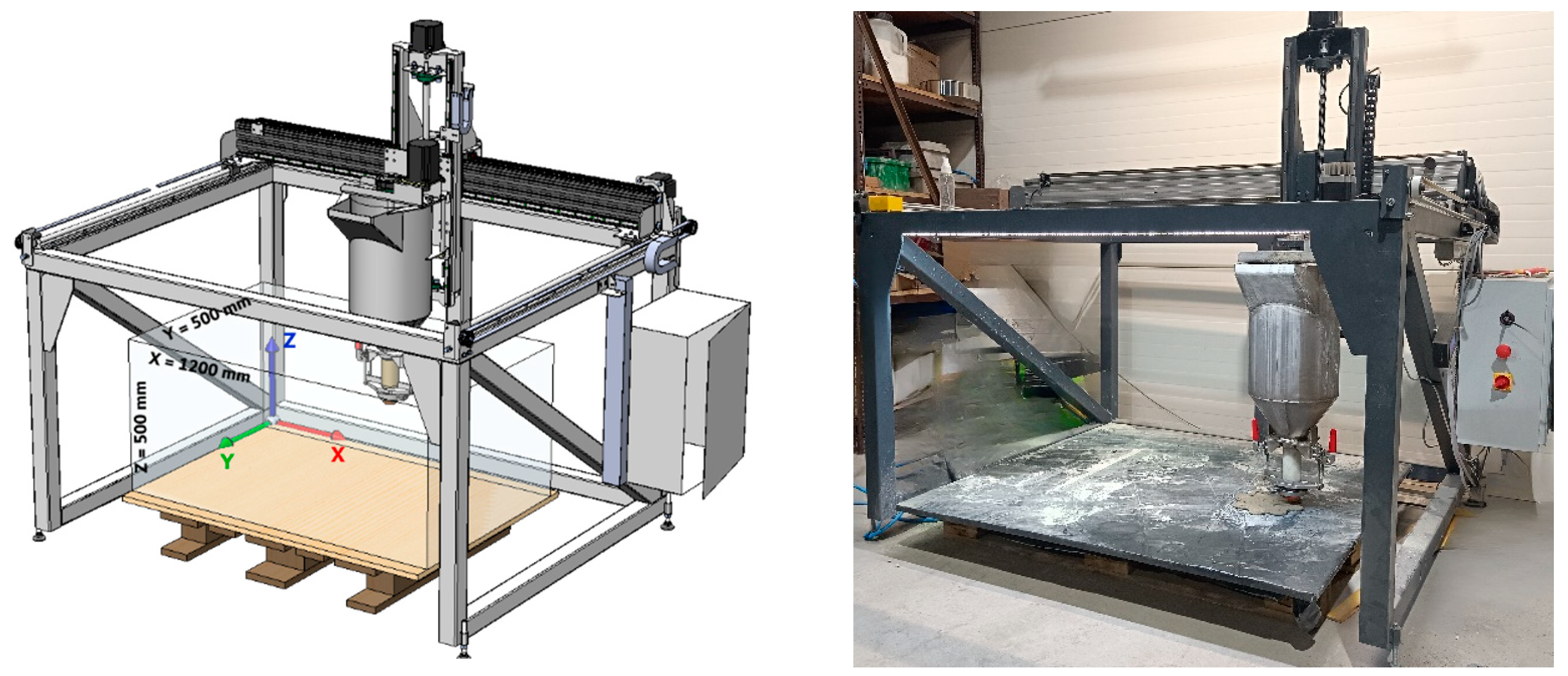
2.3. Methods
2.3.1. Flow Table Test
2.3.2. Stability and Buildability Assessment of Stability and Buildability
2.3.3. Flexural Strength Test Flexural Strength Testing Procedure
2.3.4. Apparent Density Apparent Density Determination
2.3.5. Water Absorption Water Absorption Measurement
2.3.6. Microscopy Observation
3. Results and Discussions
3.1. Consistency and Flow Table Test
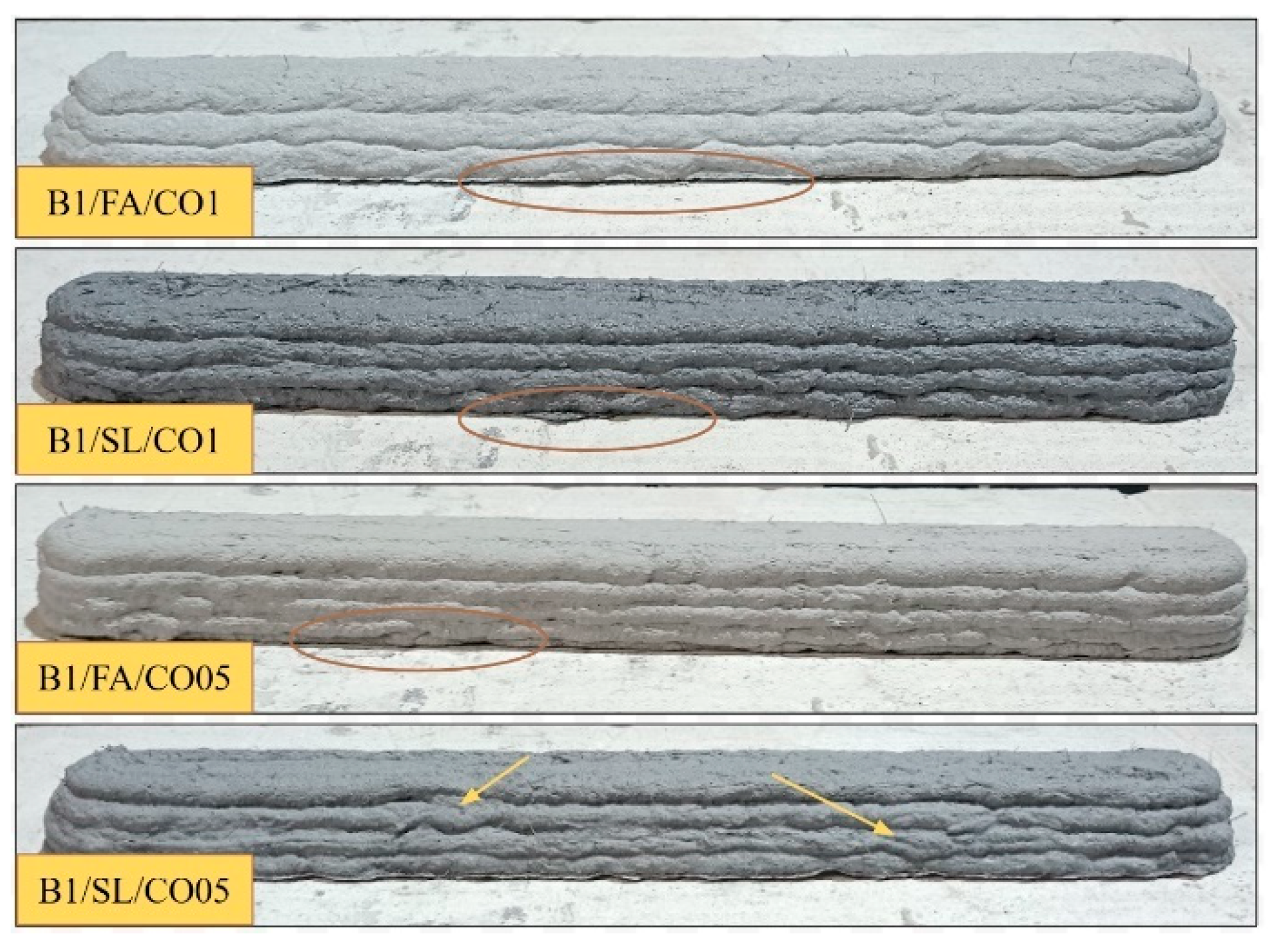
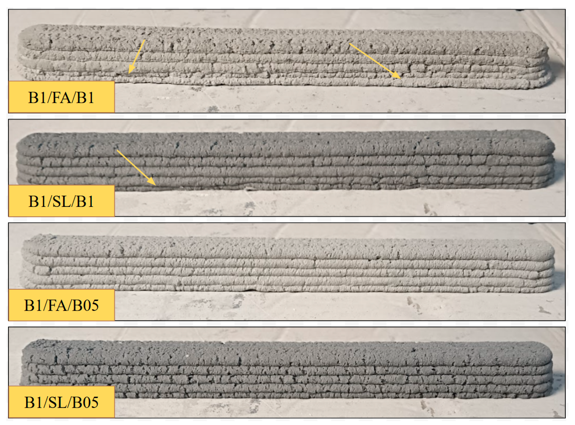
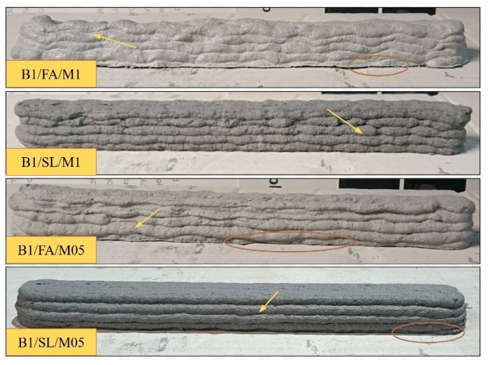
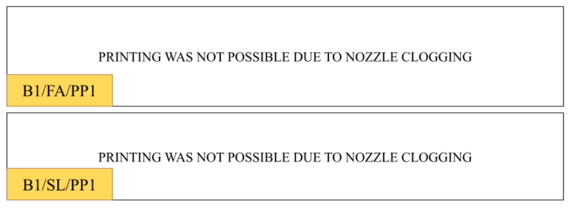
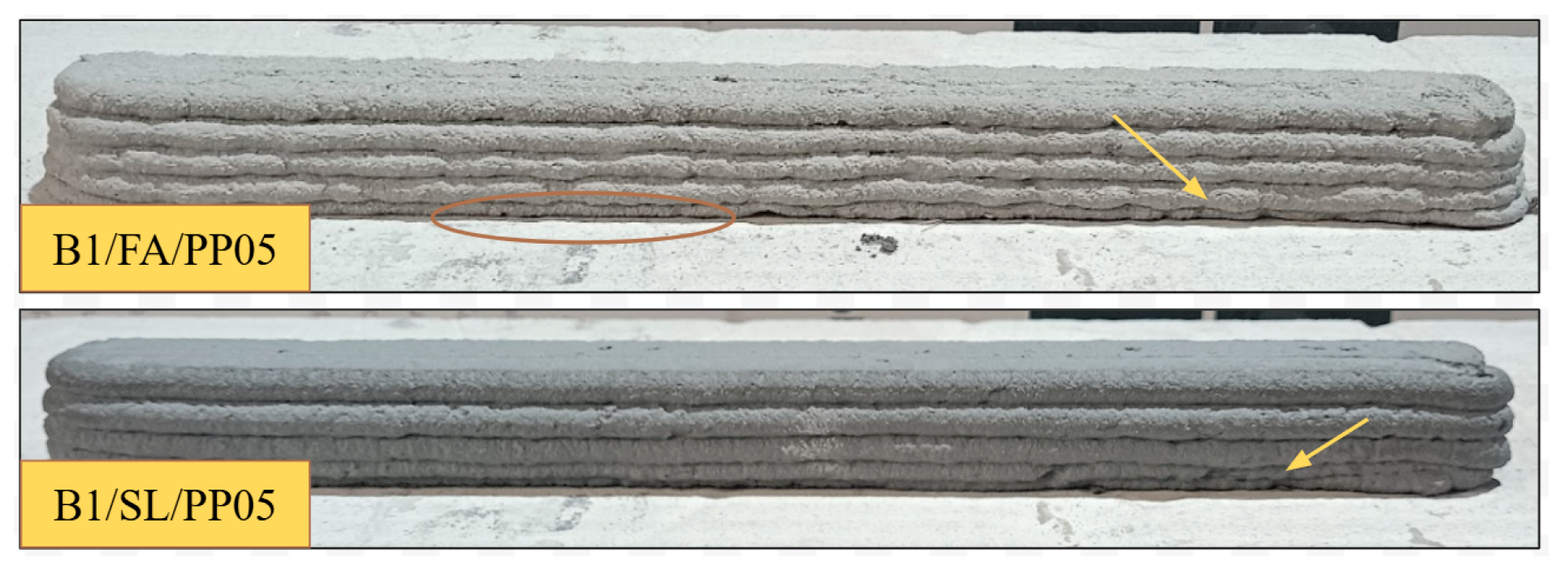
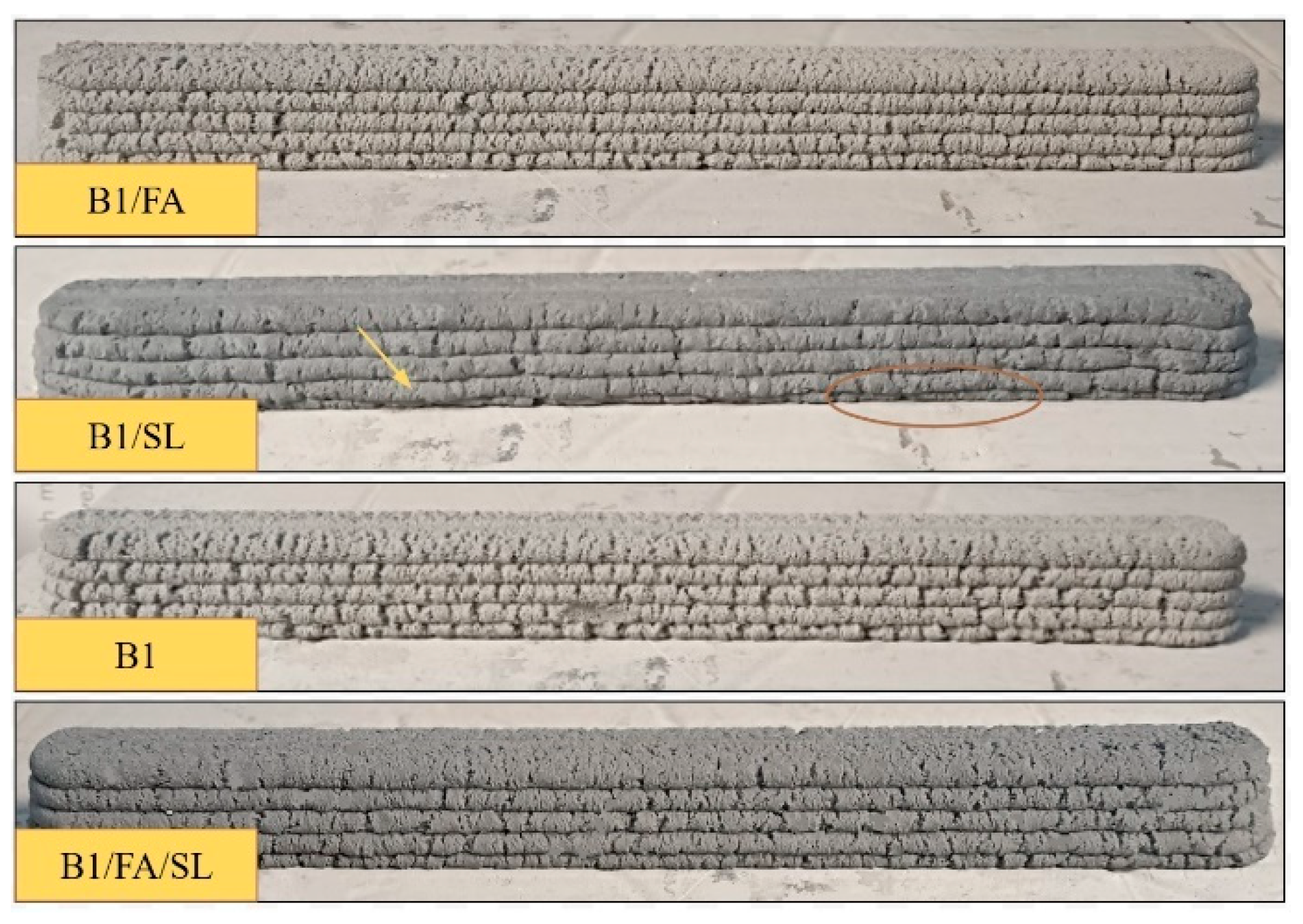
3.2. Stability and Buildability
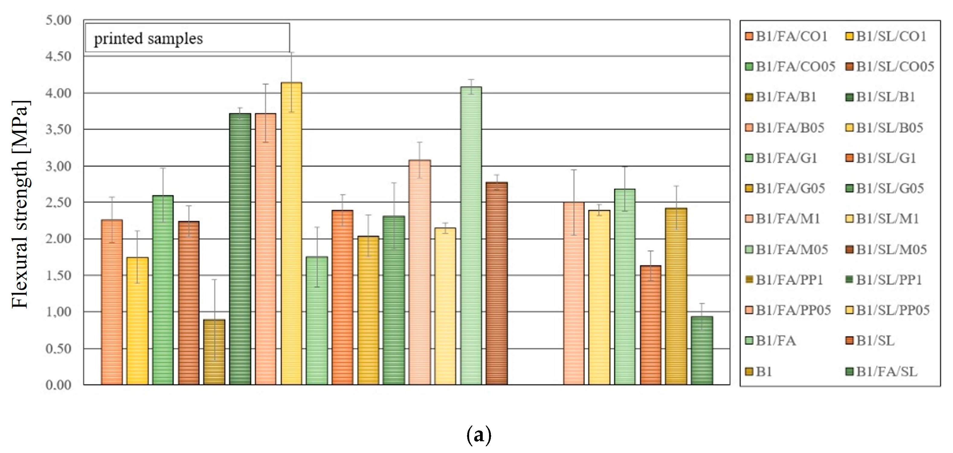
3.3. Flexural Strength Test
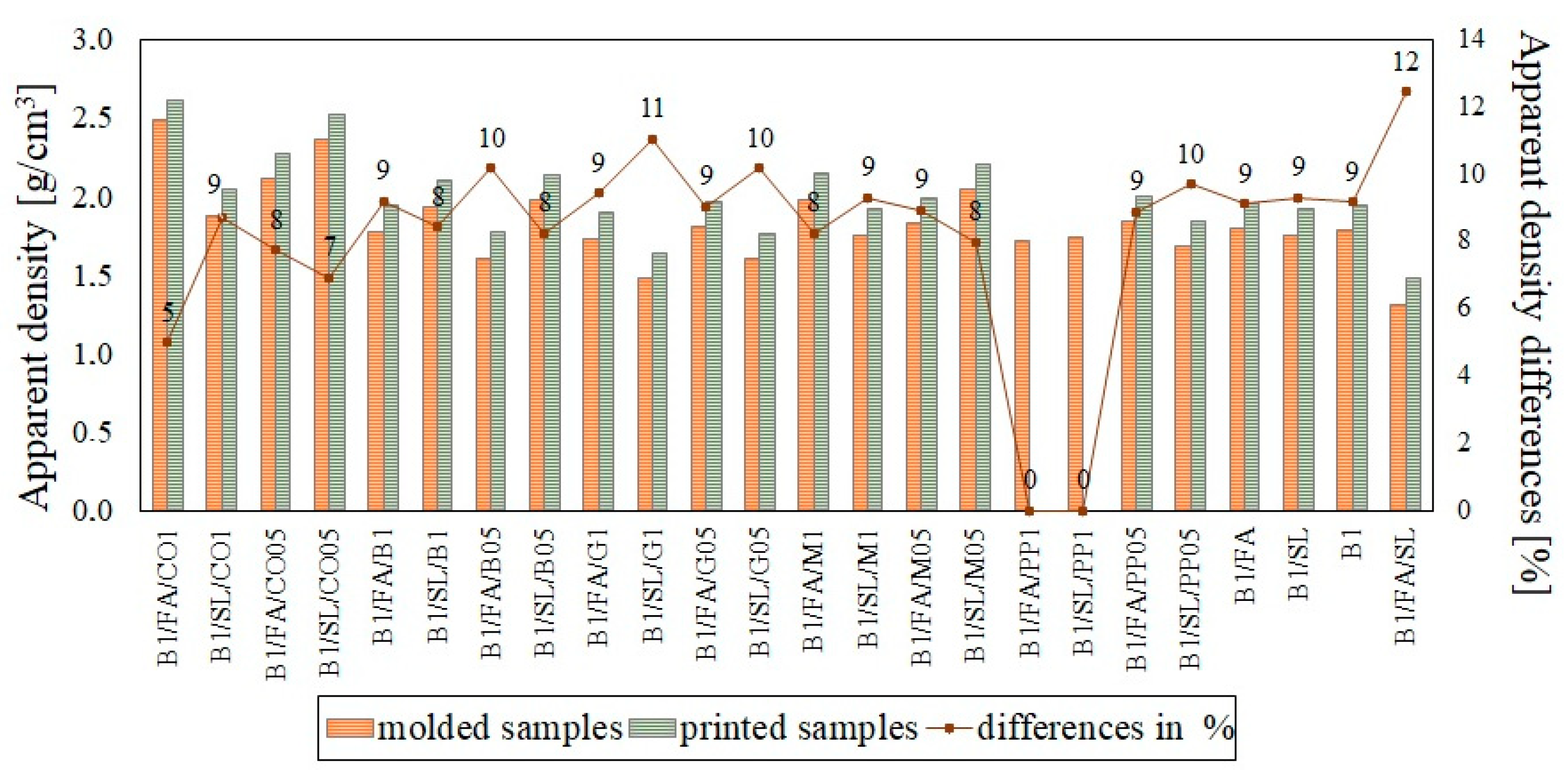
3.4. Apparent Density
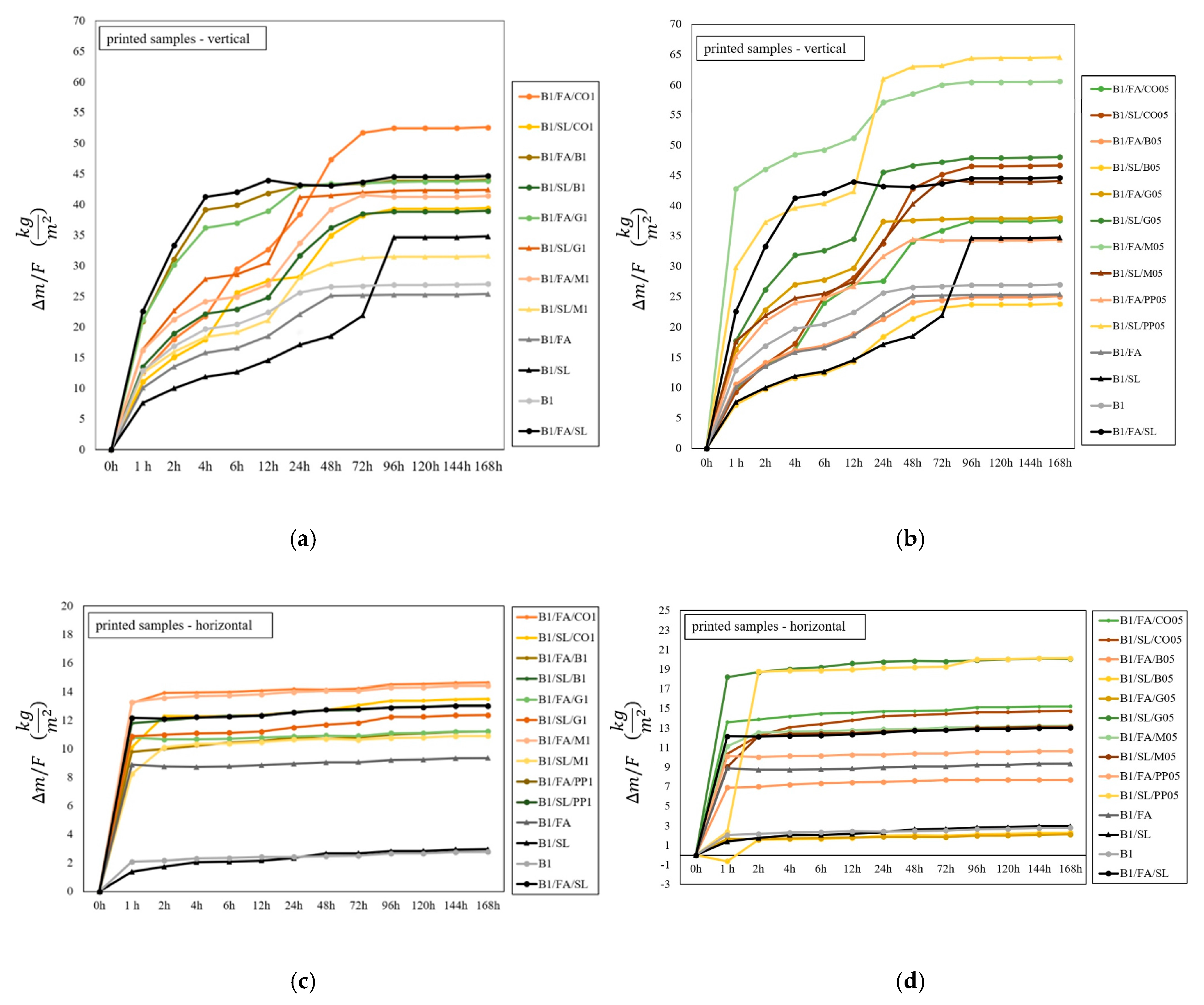
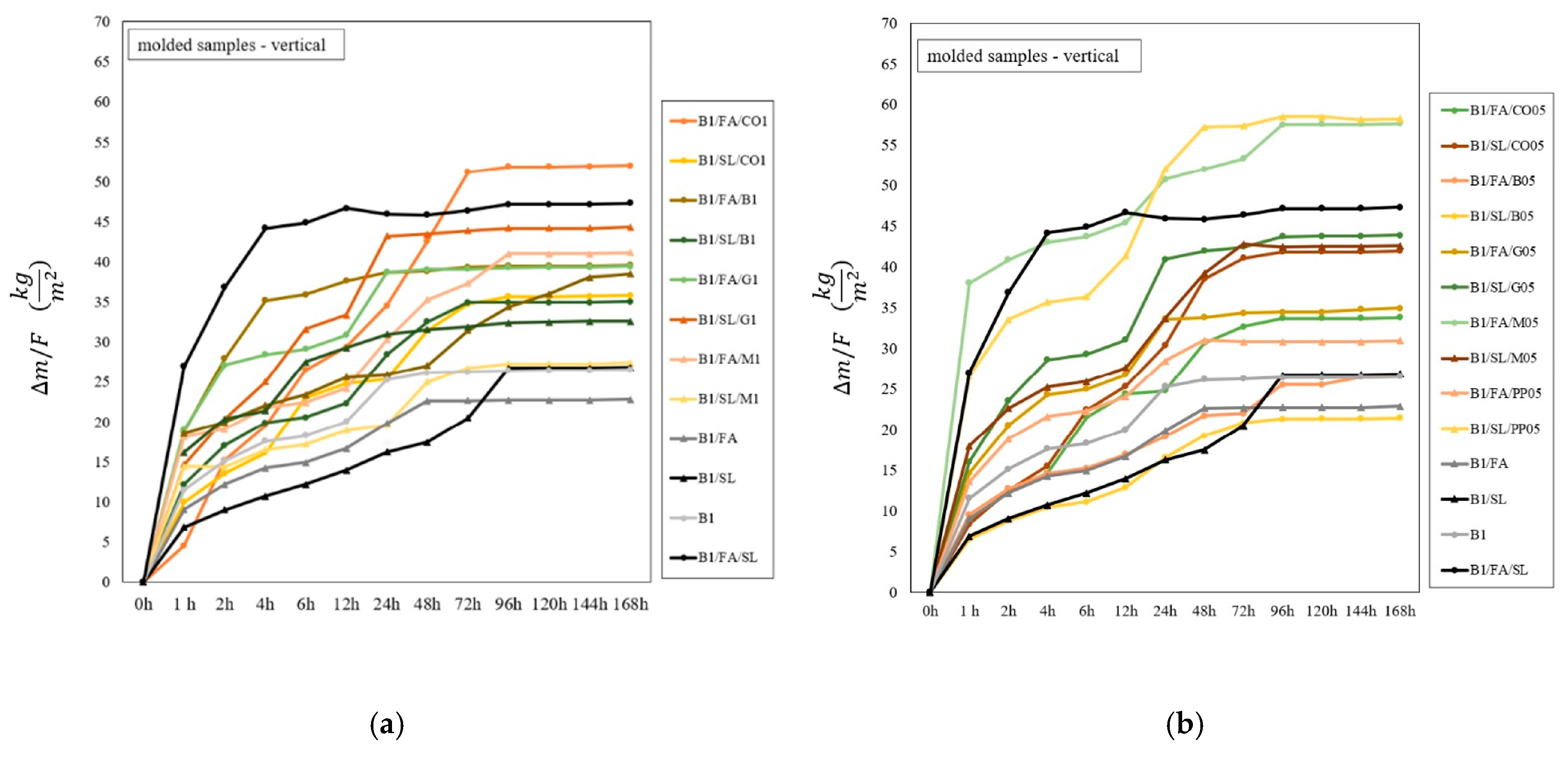
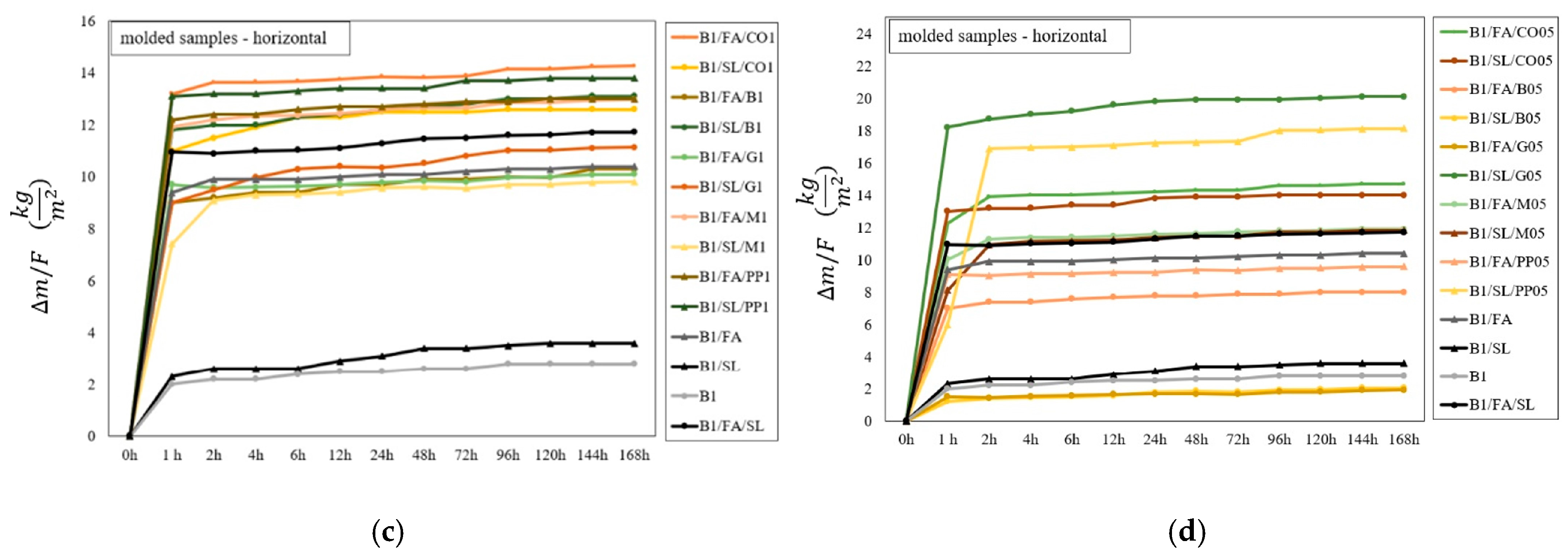
3.5. Water Absorption
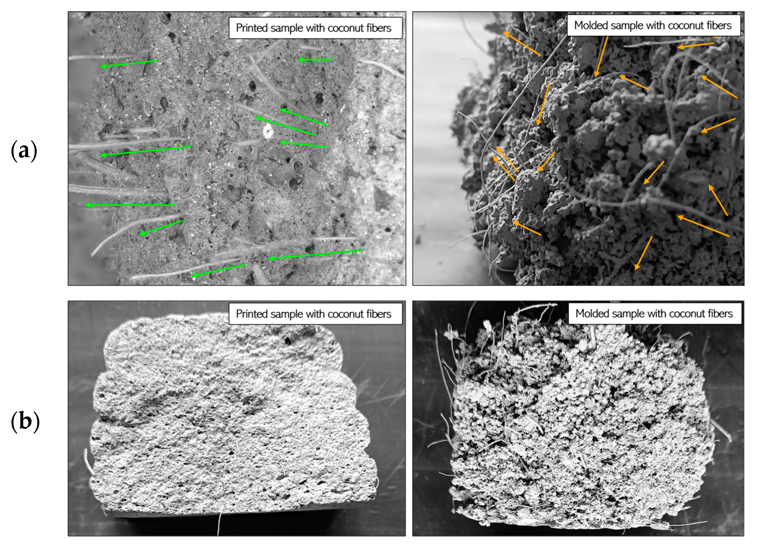
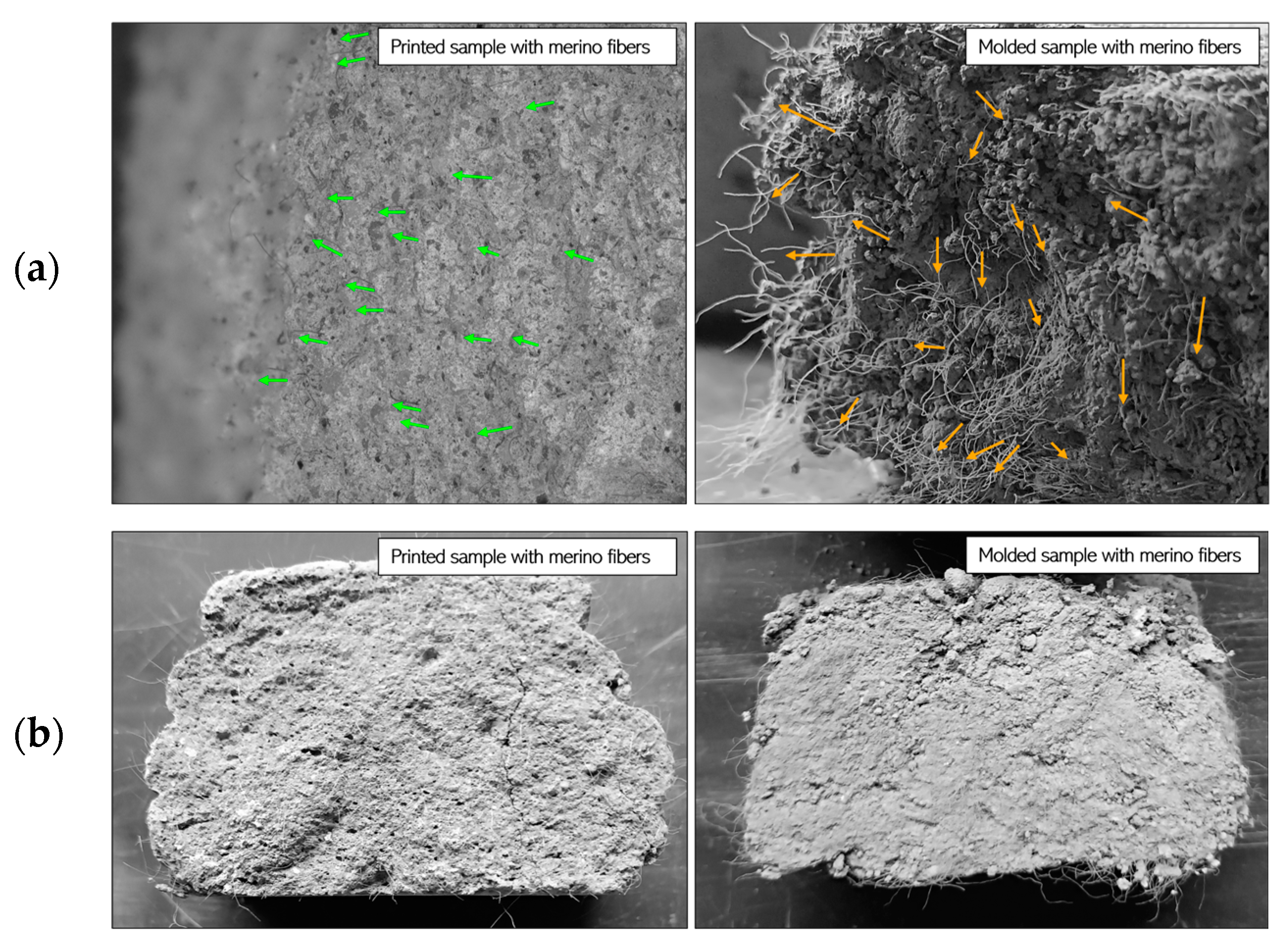
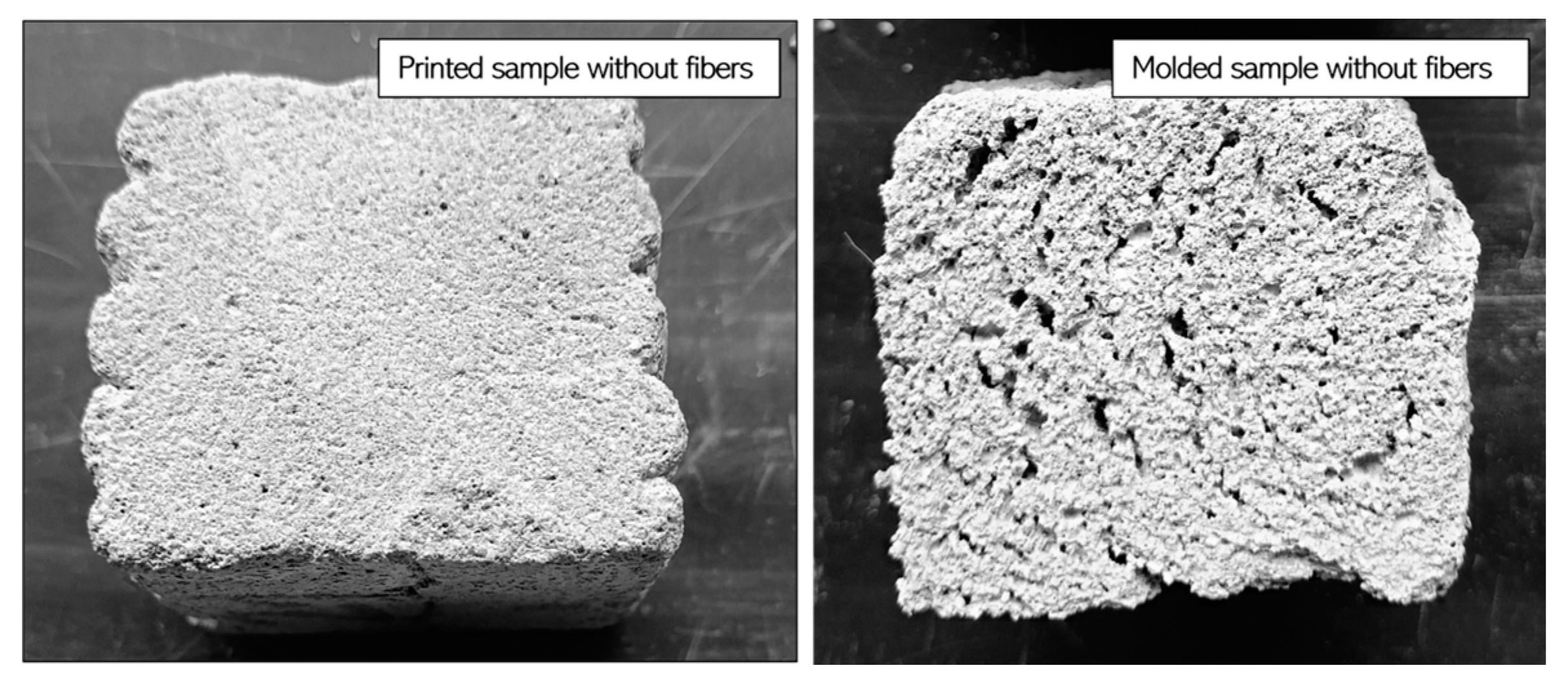
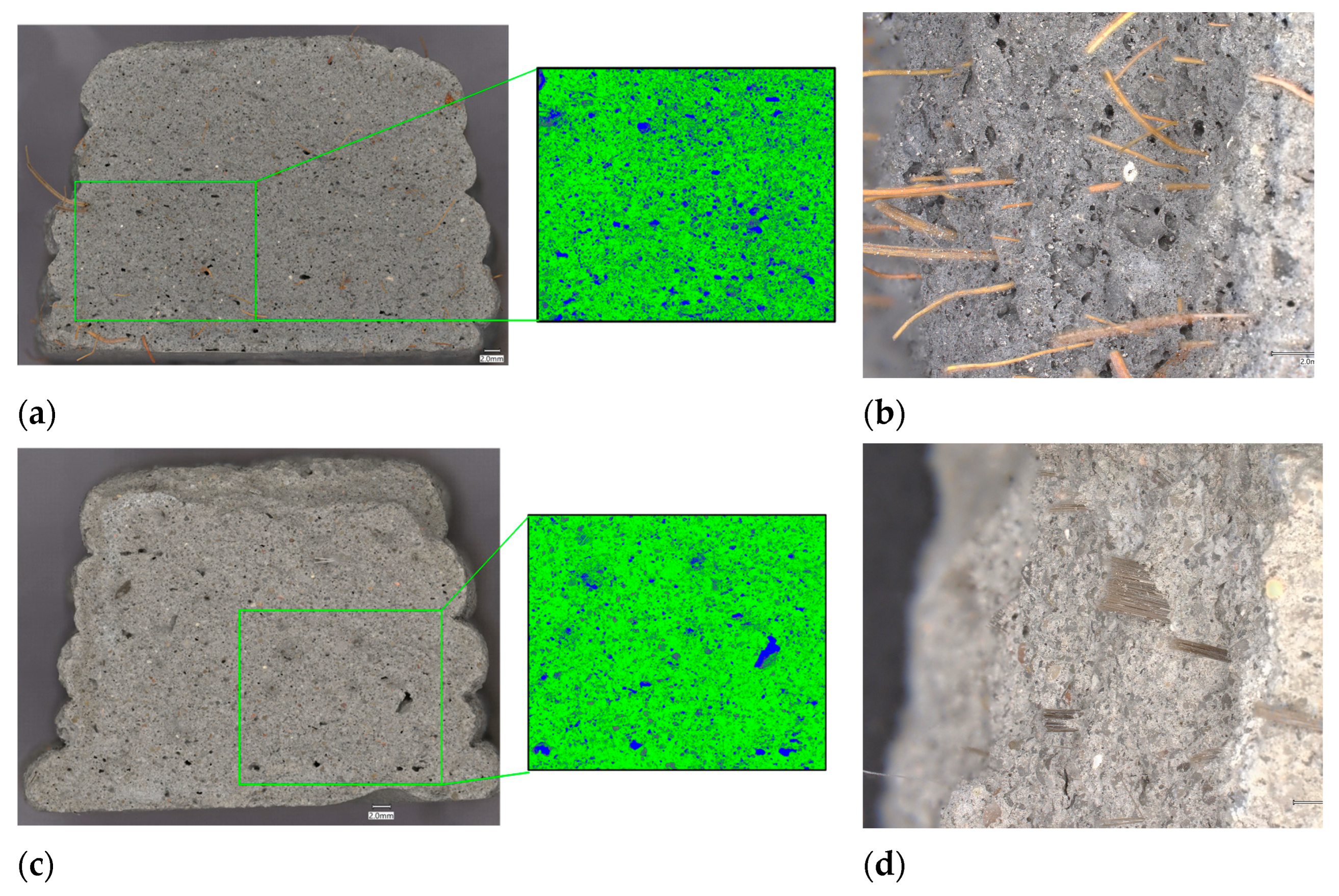
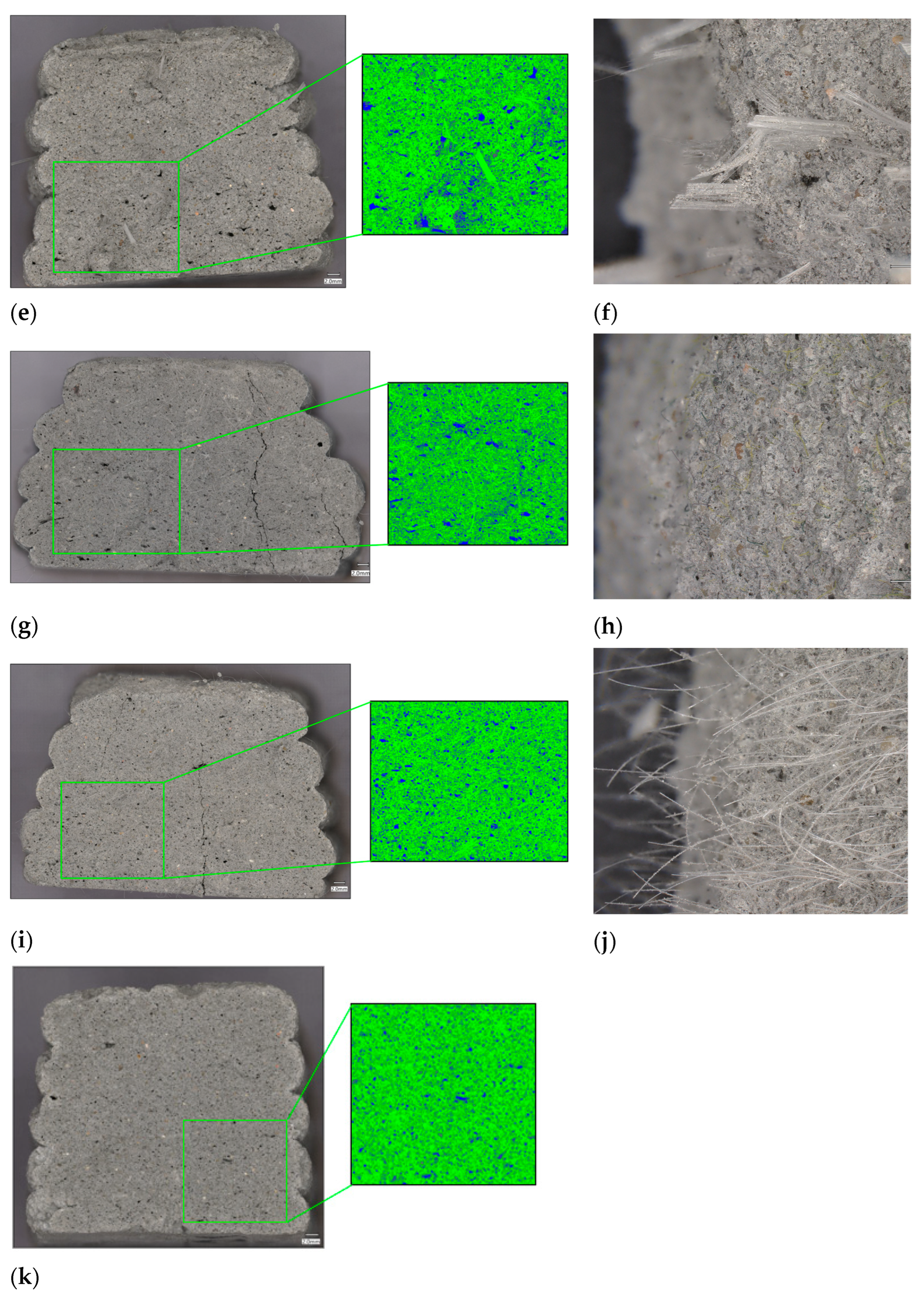
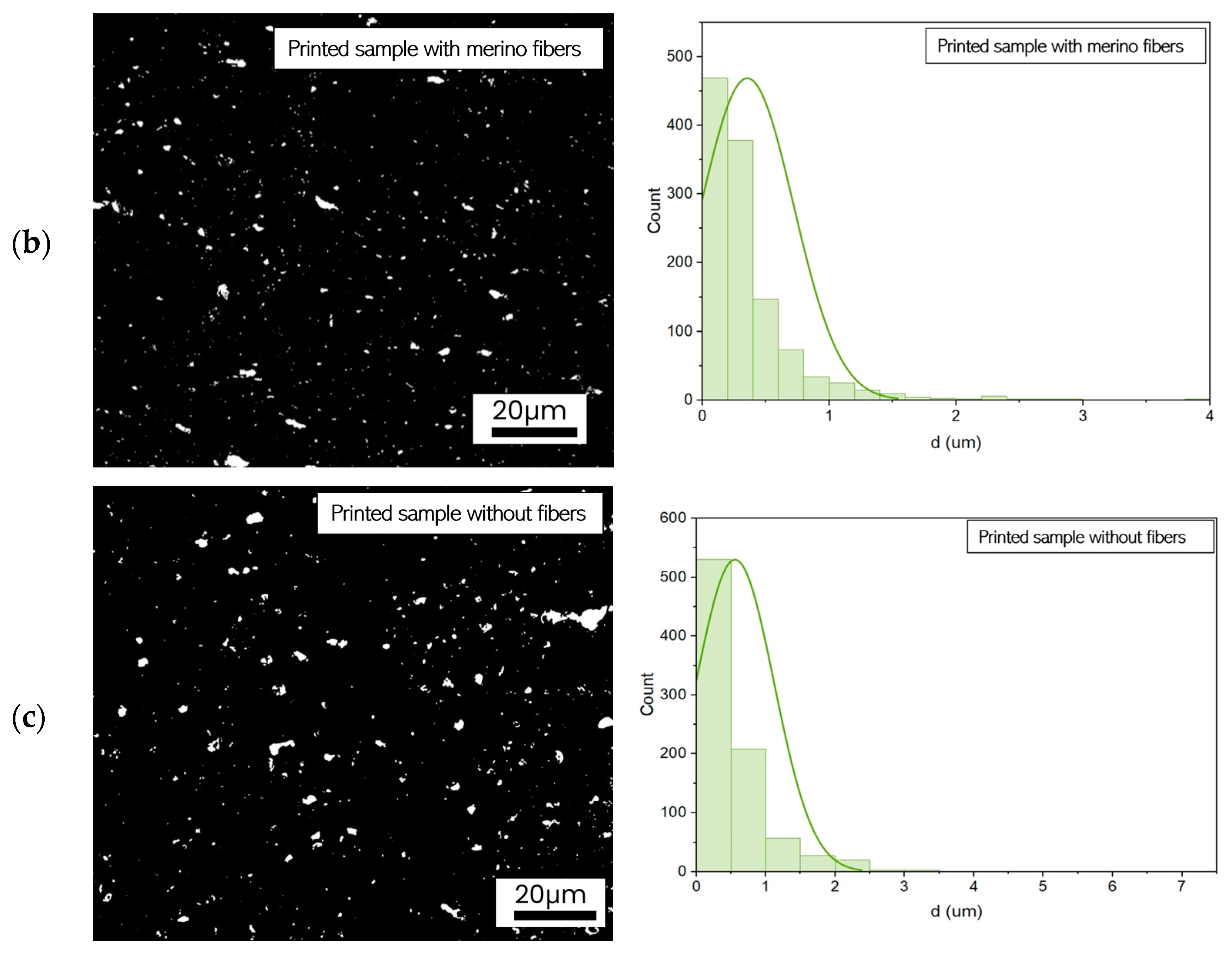
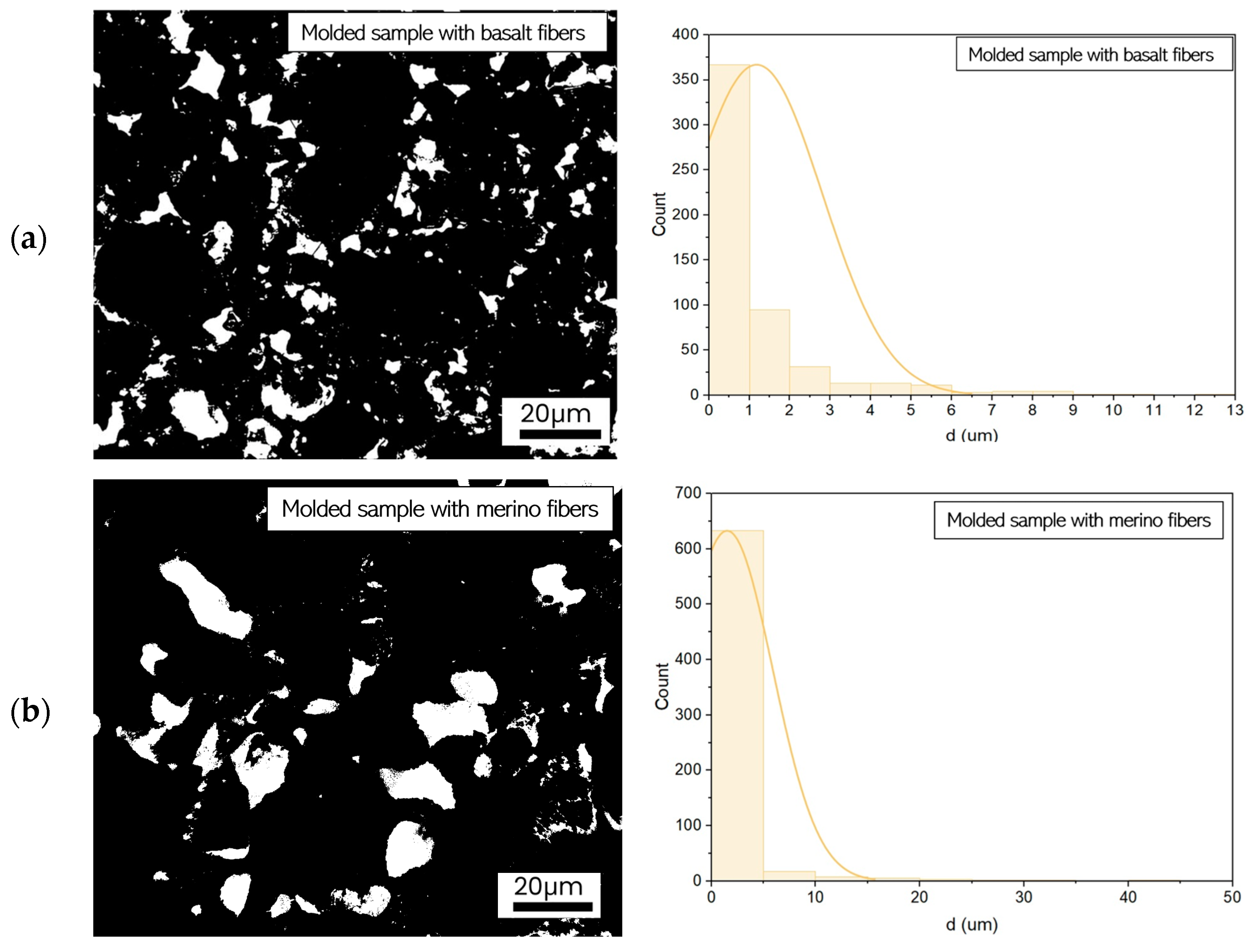
3.6. Microscopy Observations
4. Conclusions
Author Contributions
Funding
Institutional Review Board Statement
Informed Consent Statement
Data Availability Statement
Conflicts of Interest
References
- Tu, H.; Wei, Z.; Bahrami, A.; Kahla, N.B.; Ahmad, A.; Özkılıç, Y.O. Recent advancements and future trends in 3D concrete printing using waste materials. Dev. Built Environ. 2023, 16, 100187. [Google Scholar] [CrossRef]
- Rahman, M.; Rawat, S.; Yang RCh Mahil, A.; Zhang, Y.X. A comprehensive review on fresh and rheological properties of 3D printable cementitious composites. J. Build. Eng. 2024, 91, 109719. [Google Scholar] [CrossRef]
- Khan, M.; Shakeel, M.; Khan, K.; Akbar, S.; Khan, A. A Review on Fiber-Reinforced Foam Concrete. Eng. Proc. 2022, 22, 13. [Google Scholar] [CrossRef]
- Amran, M.; Fediuk, R.; Vatin, N.; Huei Lee, Y.; Murali, G.; Ozbakkaloglu, T.; Klyuev, S.; Alabduljabber, H. Fibre-Reinforced Foamed Concretes: A Review. Materials 2020, 13, 4323. [Google Scholar] [CrossRef]
- Szechyńska-Hebda, M.; Hebda, M.; Doğan-Sağlamtimur, N.; Lin, W.-T. Let’s Print an Ecology in 3D (and 4D). Materials 2024, 17, 2194. [Google Scholar] [CrossRef]
- Panda, B.; Suvash, P.; Tan, M.J. Anisotropic mechanical performance of 3D printed fiber reinforced sustainable construction material. Mater. Lett. 2017, 209, 146–149. [Google Scholar] [CrossRef]
- Zhang, P.; Lu, X. Study on Bending Strength of Cementitious Composites Based on Fiber Alignment. J. Phys. Conf. Ser. 2021, 2011, 12033. [Google Scholar] [CrossRef]
- Pham, L.; Tran, P.; Sanjayan, J. Steel fibres reinforced 3D printed concrete: Influence of fibre sizes on mechanical performance. Constr. Build. Mater. 2020, 250, 118785. [Google Scholar] [CrossRef]
- Ma, G.; Li, Z.; Wang, L.; Wang, F.; Sanjayan, J. Mechanical anisotropy of aligned fiber reinforced composite for extrusion-based 3D printing. Constr. Build. Mater. 2019, 202, 770–783. [Google Scholar] [CrossRef]
- Scheurer, M.; Quenzel, P.; Nölke, P.; Reuter-Schniete, J.; Gries, T. Investigating the feasibility of using carbon fiber tapes as reinforcement for 3D concrete printing. Civil Engineering Design. 2021, 3, 136–142. [Google Scholar] [CrossRef]
- Chu, S.H.; Li, L.G.; Kwan, A.K.H. Development of extrudable high strength fiber reinforced concrete incorporating nano calcium carbonate. Addit. Manuf. 2021, 37, 101617. [Google Scholar] [CrossRef]
- Li, L.G.; Xiao, B.-F.; Cheng, C.-M.; Xie, H.-Z.; Kwan, A.K.H. Adding Glass Fibers to 3D Printable Mortar: Effects on Printability and Material Anisotropy. Buildings 2023, 13, 2295. [Google Scholar] [CrossRef]
- Bong, S.H.; Nematollahi, B.; Arunothayan, A.; Xia, M.; Sanjayan, J. Effect of Wollastonite Micro-Fiber Addition on Properties of 3D-Printable ‘Just-Add-Water’ Geopolymers. In Second RILEM International Conference on Concrete and Digital Fabrication: Digital Concrete 2020; Springer: Cham, Switzerland, 2020. [Google Scholar] [CrossRef]
- Ramezani, A.; Modaresi, S.; Dashti, P.; GivKashi, M.R.; Moodi, F.; Ramezanianpour, A.A. Effects of Different Types of Fibers on Fresh and Hardened Properties of Cement and Geopolymer-Based 3D Printed Mixtures: A Review. Buildings 2023, 13, 945. [Google Scholar] [CrossRef]
- Jiang, Q.; Liu, Q.; Wu, S.; Zheng, H.; Sun, W. Modification effect of nanosilica and polypropylene fiber for extrusion-based 3D printing concrete: Printability and mechanical anisotropy. Addit. Manuf. 2022, 56, 102944. [Google Scholar] [CrossRef]
- Liu, B.; Liu, X.; Li, G.; Geng, S.; Li, Z.; Weng, Y.; Qian, Y. Study on anisotropy of 3D printing PVA fiber reinforced concrete using destructive and non-destructive testing methods. Case Stud. Constr. Mater. 2022, 17, e01519. [Google Scholar] [CrossRef]
- Lyu, Q.; Dai, P.; Chen, A. Mechanical strengths and optical properties of translucent concrete manufactured by mortar-extrusion 3D printing with polymethyl methacrylate (PMMA) fibers. Compos. Part B Eng. 2023, 268, 111079. [Google Scholar] [CrossRef]
- Sun, J.; Wu, Q.; Wang, Y.; Liu, H.; Zhao, H.; Cui, W.; Zhang, W.; Wang, X. 3D printed concrete incorporating waste rubber: Anisotropic properties and environmental impact analysis. J. Mater. Res. Technol. 2024, 33, 2773–2784. [Google Scholar] [CrossRef]
- Korniejenko, K.; Łach, M.; Chou, S.-Y.; Lin, W.-T.; Cheng, A.; Hebdowska-Krupa, M.; Gądek, S.; Mikuła, J. Mechanical Properties of Short Fiber-Reinforced Geopolymers Made by Casted and 3D Printing Methods: A Comparative Study. Materials 2020, 13, 579. [Google Scholar] [CrossRef] [PubMed]
- Tarhan, Y.; Perrot, A. Reinforcement of 3D printable earth-based mortar with natural textile material. Mater. Today Proc. 2023; in press. [Google Scholar] [CrossRef]
- Varela, H.; Pimentel Tinoco, M.; Mendoza Reales, O.A.; Dias Toledo Filho, R.; Barluenga, G. Sisal fiber reinforced mortar for 3D printing applications in construction. Procedia Struct. Integr. 2024, 64, 1427–1434. [Google Scholar] [CrossRef]
- Zhang, Y.; Zhu, Y.; Ren, Q.; He, B.; Jiang, Z.; Tittelboom, K.V.; De Schutter, G. Comparison of printability and mechanical properties of rigid and flexible fiber-reinforced 3D printed cement-based materials. Constr. Build. Mater. 2023, 400, 132750. [Google Scholar] [CrossRef]
- Warsi, S.B.F.; Panda, B.; Biswas, P. Exploring fibre addition methods and mechanical properties of fibre-reinforced 3D printed concrete: A review. Dev. Built Environ. 2023, 16, 100295. [Google Scholar] [CrossRef]
- Shakor, P.; Nejadi, S.; Sutjipto, S.; Paul, G.; Gowripalan, N. Effects of deposition velocity in the presence/absence of E6-glass fibre on extrusion-based 3D printed mortar. Addit. Manuf. 2020, 32, 101069. [Google Scholar] [CrossRef]
- Zhao, Y.; Wu, X.; Zhu, L.; Yang, Z.; Wang, Y.; Xi, X. The Influence of Polypropylene Fiber on the Working Performance and Mechanical Anisotropy of 3D Printing Concrete. J. Adv. Concr. Technol. 2021, 19, 1264–1274. [Google Scholar] [CrossRef]
- Rudziewicz, M.; Maroszek, M.; Góra, M.; Dziura, P.; Mróz, K.; Hager, I.; Hebda, M. Feasibility Review of Aerated Materials Application in 3D Concrete Printing. Materials 2023, 16, 6032. [Google Scholar] [CrossRef]
- Markin, V.; Ivanova, I.; Fataei, S.; Reißig, S.; Mechtcherine, V. Investigation on Structural Build-Up of 3D Printable Foam Concrete. In Second RILEM International Conference on Concrete and Digital Fabrication: Digital Concrete 2020; RILEM Book Series; Springer: Berlin/Heidelberg, Germany, 2020; pp. 301–311. [Google Scholar]
- Ma, X.; Li, C.; Chen, H.; Wei, Y.; Weng, Y.; Li, S.; Hojiboev, D. Research on the Improving Performance of Foam Concrete Applied to the Filling of Natural Gas Pipeline Cross-River Tunnel. Materials 2022, 15, 7461. [Google Scholar] [CrossRef]
- Haller, T.; Beuntner, N.; Gutsch, H.; Thienel, K.C. Challenges on pumping infra-lightweight concrete based on highly porous aggregates. J. Build. Eng. 2023, 65, 105761. [Google Scholar] [CrossRef]
- Falliano, D.; Parmigiani, S.; Suarez-Riera, D.; Ferro, G.; Restuccia, L. Stability, flexural behavior and compressive strength of ultra-lightweight fiber-reinforced foamed concrete with dry density lower than 100 kg/m3. J. Build. Eng. 2022, 51, 104329. [Google Scholar] [CrossRef]
- Selija, K.; Gandhi, I.S.R. Comprehensive investigation into the effect of the newly developed natural foaming agents and water to solids ratio on foam concrete behaviour. J. Build. Eng. 2022, 58, 105042. [Google Scholar] [CrossRef]
- Liu, C.; Chen, Y.; Xiong, Y.; Jia, L.; Ma LWang, X.; Chen, C.; Banthia, N.; Zhang, Y. Influence of HPMC and SF on buildability of 3D printing foam concrete: From water state and flocculation point of view. Compos. Part B Eng. 2022, 242, 110075. [Google Scholar] [CrossRef]
- Pasupathy, K.; Ramakrishnan, S.; Sanjayan, J. Enhancing the properties of foam concrete 3D printing using porous aggregates. Cem. Concr. Compos. 2022, 133, 104687. [Google Scholar] [CrossRef]
- Li, S.; Chen, B.; Chen, Z.; Gao, Z. Performance assessment of basalt fiber reinforced foamed concrete under freeze-thaw conditions using advanced acoustic emission parameters. Constr. Build. Mater. 2024, 440, 137444. [Google Scholar] [CrossRef]
- Lei, Z.; Li, Q.; Zhou, Y.; Yin, B. Mechanical performance and reinforcing mechanisms of foamed concrete strengthened by carbon fibers. J. Build. Eng. 2024, 97, 110765. [Google Scholar] [CrossRef]
- Wang, X.; Jin, Y.; Ma, Q.; Li, X. Performance and mechanism analysis of natural fiber-reinforced foamed concreto. Case Stud. Constr. Mater. 2024, 21, e03476. [Google Scholar] [CrossRef]
- Awang, H.; Mydin, M.A.O.; Roslan, A.F. Effects of fibre on drying shrinkage, compressive and flexural strength of lightweight foamed concrete. Adv. Mat. Res. 2012, 587, 144–149. [Google Scholar] [CrossRef]
- Zheng, G.; Shi, Y.; Li, Q.; Yang, Q.; Lu, X.; Zhang, X.; Cheng, X. Study on Properties of Fiber Reinforced Foam Concret 7 th International Conference on the Durability of Concrete Structures. Available online: https://docs.lib.purdue.edu/cgi/viewcontent.cgi?article=1677&context=icdcs (accessed on 2 January 2025).
- Li, L.; Wang, W.; Wang, Y.; Li, D.; Zhuang, M.L. Experimental study on pore structure characteristics and thermal conductivity of fibers reinforced foamed concrete. PLoS ONE 2023, 18, 287690. [Google Scholar] [CrossRef]
- Bayraktar, O.Y.; Kaplan, G.; Gencel, O.; Benli, A.; Sutcu, M. Physico-mechanical, durability and thermal properties of basalt fiber reinforced foamed concrete containing waste marble powder and slag. Constr. Build. Mater. 2021, 288, 123128. [Google Scholar] [CrossRef]
- Gencel, O.; Nodehi, M.; Bayraktar, O.Y.; Kaplan, G.; Benli, A.; Gholampour, A.; Ozbakkaloglu, T. Basalt fiber-reinforced foam concrete containing silica fume: An experimental study. Constr. Build. Mater. 2022, 326, 126861. [Google Scholar] [CrossRef]
- Gavi, K.; Olusegun, J. The Future of Construction: Leveraging Automation and AI Integration for Smarter, More Efficient Building Practices. 2024. Available online: https://www.researchgate.net/publication/386507818_The_Future_of_Construction_Leveraging_Automation_and_AI_Integration_for_Smarter_More_Efficient_Building_Practices (accessed on 2 January 2025).
- Rathod, D.; Raichura, U.; Pitroda, J.; Rathod, J.; Patel, R. Analyzing on-Site and off-Site Automation in the Construction Industry: A Comprehensive Overview. Indian J. Nat. Prod. 2024, 14, 68880–68888. [Google Scholar]
- Liu, Y.; Alias, A.H.; Haron, N.A.; Bakar, N.A.; Wang, H. Robotics in the Construction Sector: Trends, Advances, and Challenges. J. Intell. Robot. Syst 2024, 110, 72. [Google Scholar] [CrossRef]
- Akanbi, L.A.; Oyedele, A.O.; Oyedele, L.O.; Salami, R.O. Deep learning model for Demolition Waste Prediction in a circular economy. J. Clean. Prod. 2020, 274, 122843. [Google Scholar] [CrossRef]
- Rane, N.; Choudhary, S.; Rane, J. A New Era of Automation in the Construction Industry: Implementing Leading-Edge Generative Artificial Intelligence, such as ChatGPT or Bard. SSRN Electron. J. 2024. [Google Scholar] [CrossRef]
- PN-EN 197-1:2012; Cement—Part 1: Composition, Specifications and Conformity Criteria for Common Cements. Polish Committee for Standardization: Warsaw, Poland, 2012.
- Kearsley, E.P.; Wainwright, P.J. The effect of high fly ash content on the compressive strength of foamed concrete. Cem. Concr. Res. 2001, 31, 105–112. [Google Scholar] [CrossRef]
- Available online: https://www.holcim.pl/sites/poland2/files/2024-03/karta-charakterystyki-dla-cementu-cem-iv-b-v-32-5-n-cem-iv-b-v-42-5-n-lh-cem-iv-b-v-42-5-n-lh-na.pdf (accessed on 28 December 2024).
- Rudziewicz, M.; Maroszek, M.; Hutyra, A.; Góra, M.; Rusin-Żurek, K.; Hebda, M. Influence of Foaming Agents and Stabilizers on Porosity in 3D Printed Foamed Concrete. Processes 2025, 13, 403. [Google Scholar] [CrossRef]
- PN-EN 1015-3:2000; Metody Badań Zapraw do Murów—Określenie Konsystencji Świeżej Zaprawy (za Pomocą Stolika Rozpływu). Polish Committee for Standardization: Warsaw, Poland, 2004.
- Maroszek, M.; Rudziewicz, M.; Hutyra, A.; Dziura, P.; Hebda, M. Evaluation of 3D Concrete Printing Extrusion Efficiency. Appl. Sci. 2024, 14, 11866. [Google Scholar] [CrossRef]
- EN 13892-2:2004; Bending and Compression Strength. BSI: London, UK, 2002.
- Xu, N.; Qian, Y. Effects of fiber volume fraction, fiber length, water-binder ratio, and nanoclay addition on the 3D printability of strain-hardening cementitious composites (SHCC). Cem. Concr. Compos. 2023, 139, 105066. [Google Scholar] [CrossRef]
- Rudziewicz, M.; Maroszek, M.; Setlak, K.; Góra, M.; Hebda, M. Optimization of Foams—Polypropylene Fiber-Reinforced Concrete Mixtures Dedicated for 3D Printing. Materials 2024, 17, 4106. [Google Scholar] [CrossRef]
- Marczyk, J.; Ziejewska, C.; Pławecka, K.; Bak, A.; Łach, M.; Korniejenko, K.; Hager, I.; Mikuła, J.; Lin, W.-T.; Hebda, M. Optimizing theL/S Ratio in Geopolymers for the Production of Large-Size Elementswith 3D Printing Technology. Materials 2022, 15, 3362. [Google Scholar] [CrossRef]
- Fantilli, A.P.; Sicardi, S.; Dotti, F. The Use of Wool as Fiber-Reinforcement in Cement-Based Mortar. Acad. J. Civ. Eng. 2015, 33, 341–346. [Google Scholar] [CrossRef]
- Sun, J.; Aslani, F.; Lu, J.; Wang, L.; Huang, Y.; Ma, G. Fibre-reinforced lightweight engineered cementitious composites for 3D concrete printing. Ceram. Int. 2021, 47, 27107–27121. [Google Scholar] [CrossRef]
- Boddepalli, U.; Gandhi, I.S.R.; Panda, B. Synergistic effect of fly ash and polyvinyl alcohol fibers in improving stability, rheology, and mechanical properties of 3D printable foam concrete. Constr. Build. Mater. 2024, 429, 136464. [Google Scholar] [CrossRef]
- Luo, S.; Jin, W.; Wu, W.; Zhang, K. Rheological and mechanical properties of polyformaldehyde fiber reinforced 3D-printed high-strength concrete with the addition of fly ash. J. Build. Eng. 2024, 98, 111387. [Google Scholar] [CrossRef]
- Sikora, P.; Techman, M.; Federowicz, K.; El-Khayatt, A.M.; Saudi, H.A.; Elrahman, M.A.; Hoffmann, M.; Stephan, D.; Chung, S.Y. Insight into the microstructural and durability characteristics of 3D printed concrete: Cast versus printed specimens. Case Stud. Constr. Mater. 2022, 17, e01320. [Google Scholar] [CrossRef]
- Mishra, L.; Basu, G. 8—Coconut fibre: Its structure, properties and applications. In Handbook of Natural Fibres, 2nd ed.; Kozłowski, R.M., Mackiewicz-Talarczyk, M., Eds.; Woodhead Publishing Series in Textiles; Woodhead Publishing: Sawston, UK, 2020; pp. 231–255. ISBN 9780128183984. [Google Scholar] [CrossRef]
- Erdogan, U.H.; Seki, Y.; Selli, F. 9—Wool fibres. In Handbook of Natural Fibres, 2nd ed.; Kozłowski, R.M., Mackiewicz-Talarczyk, M., Eds.; Woodhead Publishing Series in Textiles; Woodhead Publishing: Sawston, UK, 2020; pp. 257–278. ISBN 9780128183984. [Google Scholar] [CrossRef]
- Alyousef, R.; Alabduljabbar, H.; Mohammadhosseini, H.; Mohamed, A.; Siddika, A.; Alrshoudi, F.; Alaskar, A. Utilization of sheep wool as potential fibrous materials in the production of concrete composites. J. Build. Eng. 2020, 30, 101216. [Google Scholar] [CrossRef]


| Oxide Composition (%) | Material | |||
|---|---|---|---|---|
| Fly Ash | Sand | CEM IV 42.5 | Coal Slag | |
| Na2O | 0.69 | - | - | - |
| MgO | 2.02 | - | 1.54 | 1.20 |
| Al2O3 | 30.71 | 13.01 | 13.44 | 31.94 |
| SiO2 | 49.85 | 81.50 | 28.46 | 48.38 |
| P2O5 | 0.71 | - | - | 0.60 |
| SO3 | 0.97 | - | 3.10 | 3.41 |
| Cl | - | - | 0.09 | 0.02 |
| K2O | 3.58 | 2.16 | 1.46 | 2.61 |
| CaO | 2.95 | 1.20 | 45.61 | 1.73 |
| Sc2O3 | - | - | 0.10 | - |
| TiO2 | 1.48 | 1.08 | 0.79 | 1.71 |
| V2O5 | 0.08 | - | 0.02 | 0.10 |
| Cr2O3 | 0.03 | - | 0.03 | 0.03 |
| MnO | 0.05 | - | 0.08 | 0.02 |
| Fe2O3 | 6.43 | 1.05 | 5.01 | 7.66 |
| CoO | - | - | 0.02 | - |
| NiO | 0.02 | - | 0.02 | 0.03 |
| CuO | 0.02 | - | 0.02 | 0.02 |
| ZnO | 0.02 | - | 0.11 | 0.01 |
| Rb2O | 0.03 | - | 0.01 | 0.02 |
| SrO | 0.13 | - | 0.06 | 0.20 |
| Y2O3 | 0.01 | - | - | 0.01 |
| ZrO2 | 0.04 | - | 0.03 | 0.09 |
| In2O3 | - | - | - | 0.01 |
| BaO | 0.15 | - | - | 0.11 |
| Ta2O5 | - | - | - | 0.01 |
| WO3 | - | - | - | 0.02 |
| Fibers | Diameter [μm] | Length [mm] | Density [g/cm3] |
|---|---|---|---|
| Coconut (CO) | 70 | 10 mm | 2.41 |
| Basalt (B) | 14 | 10 mm | 4.88 |
| Glass (G) | 20 | 12 mm | 1.88 |
| Polypropylene (PP) | 18 | 12 mm | 1.39 |
| Merino wool (M) | 18.20 | 10 mm | 4.55 |
| Component | Dosage (%) | Density (kg/m3) | Compressive Strength After 7 Days (MPa) | Compressive Strength After 28 Days (MPa) |
|---|---|---|---|---|
| Synthetic foaming agent | 2 | 1602 | 5.2 | 9.7 |
| No. | Designation of the Mixtures | w/c | Cement [%] | Sand [%] | Fly Ash [%] | Coal Slag [%] | Synthetic Foaming Agent [%] | Coconut Fibers [%] | Basalt Fibers [%] | Glass Fibers [%] | Merino Fibers [%] | Polypropylene Fibers [%] |
|---|---|---|---|---|---|---|---|---|---|---|---|---|
| 1 | B1/FA/CO1 | 0.24 | 28 | 64 | 5 | - | 5 | 1 | - | - | - | - |
| 2 | B1/SL/CO1 | 0.24 | 33 | 52 | - | 15 | 5 | 1 | - | - | - | - |
| 3 | B1/FA/CO05 | 0.24 | 28 | 64 | 5 | - | 5 | 0.5 | - | - | - | - |
| 4 | B1/SL/CO05 | 0.24 | 33 | 52 | - | 15 | 5 | 0.5 | - | - | - | - |
| 5 | B1/FA/B1 | 0.24 | 28 | 64 | 5 | - | 5 | - | 1 | - | - | - |
| 6 | B1/SL/B1 | 0.24 | 33 | 52 | - | 15 | 5 | - | 1 | - | - | - |
| 7 | B1/FA/B05 | 0.24 | 28 | 64 | 5 | - | 5 | - | 0.5 | - | - | - |
| 8 | B1/SL/B05 | 0.24 | 33 | 52 | - | 15 | 5 | - | 0.5 | - | - | - |
| 9 | B1/FA/G1 | 0.24 | 28 | 64 | 5 | - | 5 | - | - | 1 | - | - |
| 10 | B1/SL/G1 | 0.24 | 33 | 52 | - | 15 | 5 | - | - | 1 | - | - |
| 11 | B1/FA/G05 | 0.24 | 28 | 64 | 5 | - | 5 | - | - | 0.5 | - | - |
| 12 | B1/SL/G05 | 0.24 | 33 | 52 | - | 15 | 5 | - | - | 0.5 | - | - |
| 13 | B1/FA/M1 | 0.27 | 28 | 64 | 5 | - | 5 | - | - | - | 1 | - |
| 14 | B1/SL/M1 | 0.27 | 33 | 52 | - | 15 | 5 | - | - | - | 1 | - |
| 15 | B1/FA/M05 | 0.27 | 28 | 64 | 5 | - | 5 | - | - | - | 0.5 | - |
| 16 | B1/SL/M05 | 0.27 | 33 | 52 | - | 15 | 5 | - | - | - | 0.5 | - |
| 17 | B1/FA/PP1 | 0.27 | 28 | 64 | 5 | - | 5 | - | - | - | - | 1 |
| 18 | B1/SL/PP1 | 0.27 | 33 | 52 | - | 15 | 5 | - | - | - | - | 1 |
| 19 | B1/FA/PP05 | 0.27 | 28 | 64 | 5 | - | 5 | - | - | - | - | 0.5 |
| 20 | B1/SL/PP05 | 0.27 | 33 | 52 | - | 15 | 5 | - | - | - | - | 0.5 |
| 21 | B1/FA | 0.27 | 28 | 64 | 5 | - | 5 | - | - | - | - | - |
| 22 | B1/SL | 0.24 | 33 | 52 | - | 15 | 5 | - | - | - | - | - |
| 23 | B1 | 0.27 | 28 | 64 | 5 | - | 5 | - | - | - | - | - |
| 24 | B1/FA/SL | 0.24 | 33 | 52 | - | 15 | 5 | - | - | - | - | - |
| No. | Designation of the Mixtures | Time After Mixing (min) | ||
|---|---|---|---|---|
| 1 | 20 | 40 | ||
| Flow Diameter (mm) | ||||
| 1 | B1/FA/CO1 | 170 | - | - |
| 2 | B1/SL/CO1 | 165 | - | - |
| 3 | B1/FA/CO05 | 182 | 166 | - |
| 4 | B1/SL/CO05 | 171 | - | - |
| 5 | B1/FA/B1 | 176 | - | - |
| 6 | B1/SL/B1 | 170 | - | - |
| 7 | B1/FA/B05 | 172 | - | - |
| 8 | B1/SL/B05 | 168 | - | - |
| 9 | B1/FA/G1 | 168 | - | - |
| 10 | B1/SL/G1 | 161 | - | - |
| 11 | B1/FA/G05 | 172 | - | - |
| 12 | B1/SL/G05 | 168 | - | - |
| 13 | B1/FA/M1 | 157 | - | - |
| 14 | B1/SL/M1 | 160 | - | - |
| 15 | B1/FA/M05 | 160 | - | - |
| 16 | B1/SL/M05 | 171 | - | - |
| 17 | B1/FA/PP1 | 155 | - | - |
| 18 | B1/SL/PP1 | 152 | - | - |
| 19 | B1/FA/PP05 | 164 | - | - |
| 20 | B1/SL/PP05 | 162 | - | - |
| 21 | B1/FA | 220 | 191 | 167 |
| 22 | B1/SL | 200 | 172 | - |
| 23 | B1 | 200 | 178 | 155 |
| 24 | B1/FA/SL | 200 | 170 | - |
Disclaimer/Publisher’s Note: The statements, opinions and data contained in all publications are solely those of the individual author(s) and contributor(s) and not of MDPI and/or the editor(s). MDPI and/or the editor(s) disclaim responsibility for any injury to people or property resulting from any ideas, methods, instructions or products referred to in the content. |
© 2025 by the authors. Licensee MDPI, Basel, Switzerland. This article is an open access article distributed under the terms and conditions of the Creative Commons Attribution (CC BY) license (https://creativecommons.org/licenses/by/4.0/).
Share and Cite
Rudziewicz, M.; Hutyra, A.; Maroszek, M.; Korniejenko, K.; Hebda, M. 3D-Printed Lightweight Foamed Concrete with Dispersed Reinforcement. Appl. Sci. 2025, 15, 4527. https://doi.org/10.3390/app15084527
Rudziewicz M, Hutyra A, Maroszek M, Korniejenko K, Hebda M. 3D-Printed Lightweight Foamed Concrete with Dispersed Reinforcement. Applied Sciences. 2025; 15(8):4527. https://doi.org/10.3390/app15084527
Chicago/Turabian StyleRudziewicz, Magdalena, Adam Hutyra, Marcin Maroszek, Kinga Korniejenko, and Marek Hebda. 2025. "3D-Printed Lightweight Foamed Concrete with Dispersed Reinforcement" Applied Sciences 15, no. 8: 4527. https://doi.org/10.3390/app15084527
APA StyleRudziewicz, M., Hutyra, A., Maroszek, M., Korniejenko, K., & Hebda, M. (2025). 3D-Printed Lightweight Foamed Concrete with Dispersed Reinforcement. Applied Sciences, 15(8), 4527. https://doi.org/10.3390/app15084527