1. Introduction
At present, the rapid tunneling technology in China’s coal mines is in an accelerated development phase. The stride-type hydraulic support system, despite its effectiveness in reducing manual labor and improving safety, is characterized by slow advance rates and low support efficiency [
1,
2,
3]. Additionally, the multiple applications of support on the tunnel roof can result in roof fracturing, which endangers the miners’ safety [
4,
5,
6]. Therefore, this paper introduces a novel hydraulic combined support system that employs an innovative strata movement method. While effectively fulfilling its support function, this system is capable of preventing roof fracturing caused by repeated support applications, enabling simultaneous operations of “boring ahead and bolting behind”, as well as “boring and bolting concurrently”.
After a structural design is completed, verifying the stability and safety of hydraulic supports is crucial for ensuring the smooth progress of underground production [
7,
8,
9,
10,
11]. With the increasing depth of coal mining, the issues of mining pressure manifestation become increasingly prominent. Under the action of impact loads, hydraulic supports may suffer structural damage, which can further trigger safety accidents such as roof falls and rib spallings [
12,
13,
14,
15,
16,
17,
18,
19]. To enhance the stability and safety of hydraulic supports, modern engineering design has incorporated finite element software for transient dynamic analysis, allowing for the more accurate design and analysis of their structures [
20,
21,
22,
23,
24,
25]. Jin [
26] conducted theoretical, simulation, and experimental research on stride-type hydraulic advance support equipment. Xie [
27] established a dynamic model of hydraulic support based on the joint constraints method and conducted dynamic simulation studies on this hydraulic support.
Against the background of the ongoing development of rapid coal mining tunneling technology, hydraulic supports, as crucial equipment, directly influence tunneling efficiency and safety with their performance. To date, existing research has, to some extent, explored the mechanical properties of traditional hydraulic supports [
28,
29,
30]. Nevertheless, when it comes to the dynamic characteristics of hydraulic combined supports under complex conditions, research efforts are still insufficient. This study sets out to delve into the dynamic response characteristics of a newly designed hydraulic combined support under diverse impact loads through transient dynamic simulation analysis, unraveling its stress and displacement patterns. The findings will underpin the optimization of the design and safety assessment. Leveraging cutting edge simulation techniques and multidimensional analysis in line with actual working conditions, this research seeks to bridge the existing research gap and propel the advancement of hydraulic support technology.
2. Hydraulic Combination Support Model Establishment
2.1. Determination of Support Strength and Working Resistance for the Support
The operating resistance of hydraulic supports is a critical parameter for the stability of mechanized excavation tunnels. Determining the appropriate operating resistance is essential for ensuring the stable operation of the supports and the safety of the working face.
We can calculate the support strength of hydraulic supports according to the load estimation method:
In the formula, PZ represents the support strength of the hydraulic support, measured in MPa; H represents the mining height, and based on the actual mining conditions, it is taken as 3.6 m; r denotes the bulk density of the roof rock, with a value of 1.3 × 10³ kg/m3; q represents the periodic loading coefficient of the roof, and it is taken as 1.2; g denotesacceleration due to gravity, with a value of 9.8 m/s2; K represents the expansion coefficient of the roof rock, and it is taken as 1.5; α represents the working face dip angle, and it is taken as 35°; β represents the additional resistance coefficient, taken as 1.6; and η denotes the support efficiency of the support system, taken as 0.85.
Substituting the above data into the formula yields
The rated working resistance of the support system is
In the formula, QZ represents the rated working resistance, expressed in kN; Bc denotes the support canopy distance, which is 4.8 m; and Sc represents the center-to-center distance between supports, taken as 1.7 m.
Substituting the aforementioned data into the formula, the rated working resistance of the support system is calculated as
The calculation of support strength and working resistance provides a reference for the application of external loads in subsequent simulation processes.
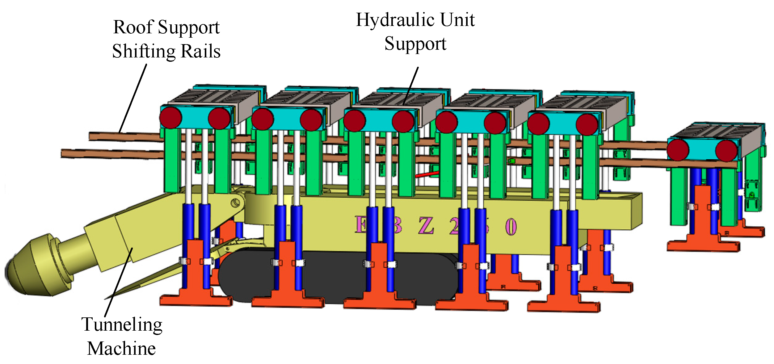
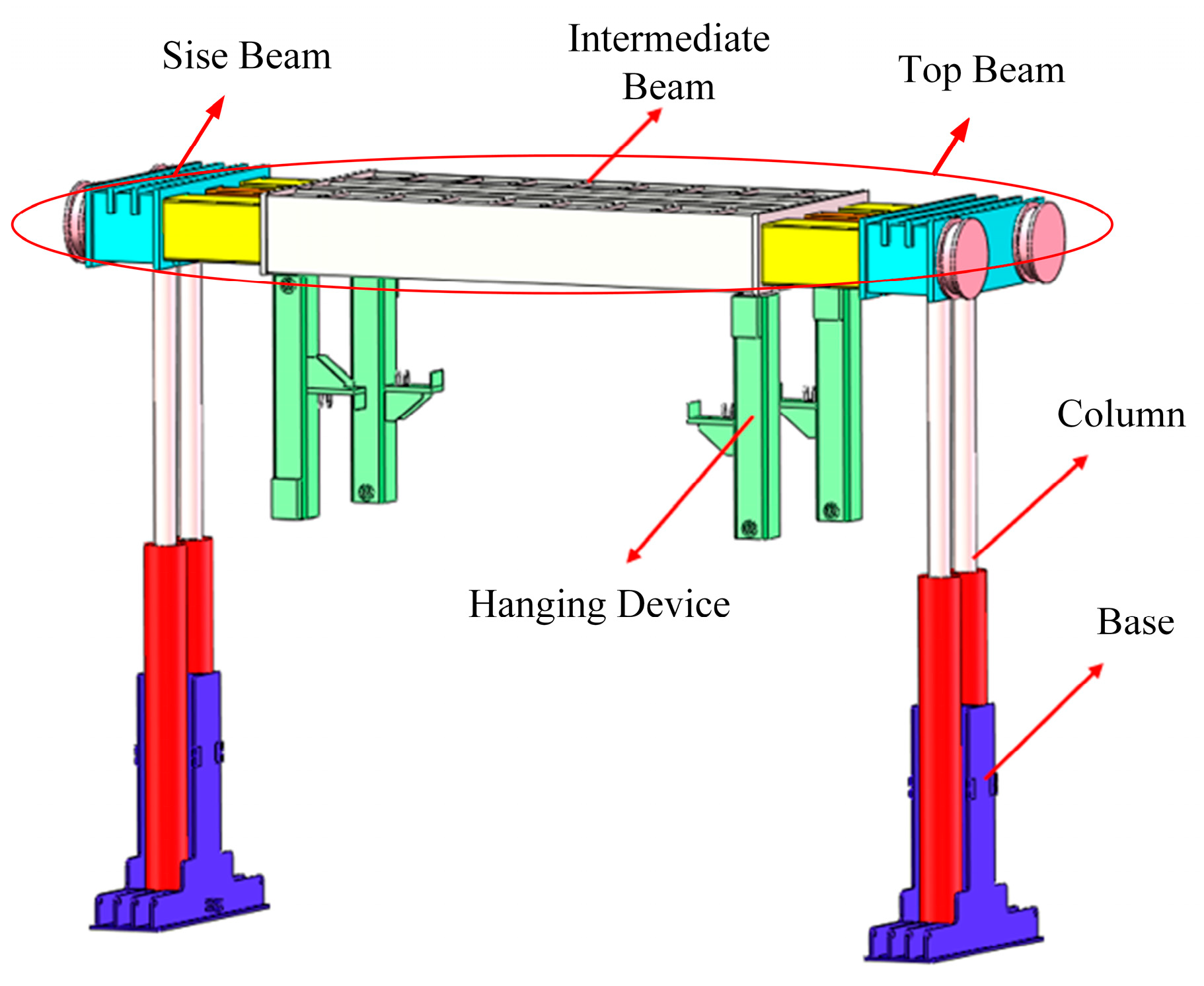
2.2. The Basic Components of a Hydraulic Support System
Several hydraulic unit supports, in conjunction with the advanced support of a heading roof using a roof shield and an advanced support system, are completed. Additionally, there are various control valves, hydraulic lines, etc. The overall scheme of the combined support is shown in
Figure 1. A static mechanical simulation was conducted on the support system, and its dimensions and other aspects meet strength requirements.
When the hydraulic combined support system is used to support the face of a tunnel, the tunneling machine does not need to retreat, and anchoring operations can be carried out simultaneously at the rear section of the hydraulic combined support system. When a void zone appears ahead of the hydraulic combined support system, workers operate the cyclic self-advancing function of the hydraulic combined support system to move the hydraulic unit supports forward (
Figure 2), ensuring that there is no interference with the cutting head of the tunneling machine.
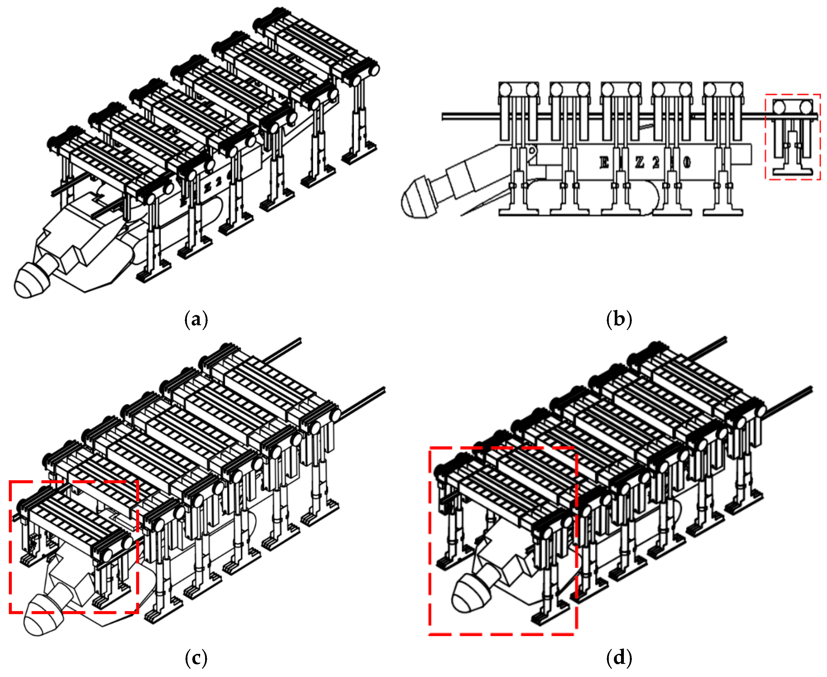
The entire operation process of the hydraulic combined support system mainly includes four steps, as shown in
Figure 3: the advancement of the roof support shifting rails, the lowering and retraction process of the support, the shifting process of the support, and the expansion and roof-propping process of the support.
This figure visually presents the entire working cycle of the hydraulic combined support system. The process starts with the extension of the support-moving rails, followed by the lowering and retracting of the support. Then, the support is shifted, and finally, the support is expanded to prop up the roof, completing a full cycle. Each step is interlinked and ensures the continuous and efficient operation of the support system during tunneling.
3. Transient Dynamic Simulation Analysis of Hydraulic Unit Supports
Firstly, a three-dimensional model established in SolidWorks2018 is imported into the ANSYS Workbench software 2018 through an intermediate data format.
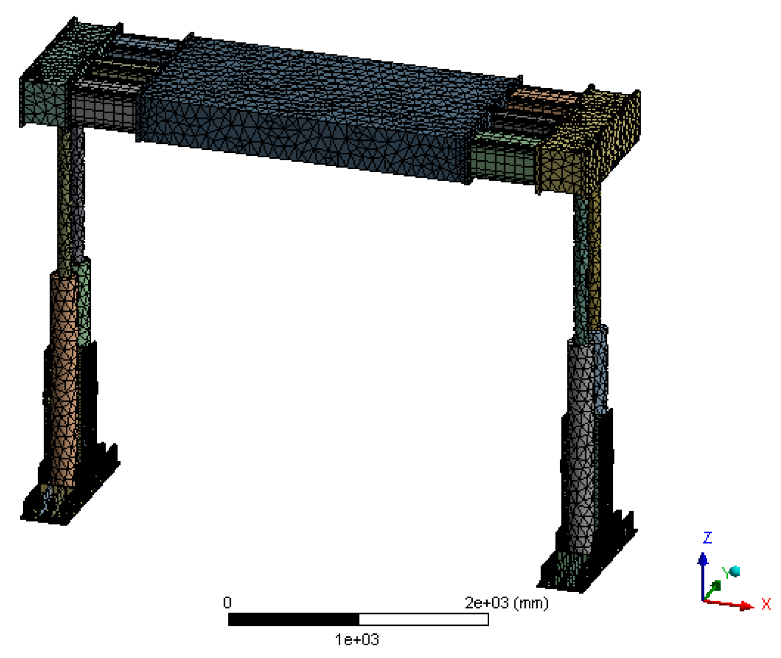
3.1. Material Properties and Grid Division
When conducting transient dynamic simulation, to ensure the accuracy of the simulation results, it is necessary to assign material properties to the support components, as shown in
Table 1.
Considering the complexity of the overall structure, this paper employs different meshing methods for various components. The top beam and columns are meshed using structured meshing, while the base and other parts are meshed using unstructured meshing. Additionally, built-in telescopic cylinders and suspension devices, which are non-load-bearing components during the support process, are simplified. Meanwhile, mesh refinement and improvement have been achieved for the main load-bearing components, such as the top beam. The meshing model of the hydraulic unit support is shown in
Figure 4, with a total of 794,688 elements, in accordance with our prior work, the same partitioning method was employed [
31].
3.2. Boundary Conditions
1. When the hydraulic support is performing support operations, the support columns are in a self-locking state. When the roof subsidence generates an exciting force acting on the support, the columns cannot descend in time, causing the top beam to bear all the impact loads. Meanwhile, the displacement variation at the pivot connection between the top beam and the columns of the hydraulic support is minimal. Therefore, constraints are added at this location.
2. The top beam is articulated to the columns through pins, and the base is connected to the columns with flanges.
3. The built-in telescopic cylinders are articulated with the intermediate beam and side beams.
We applied a constraint to the hinge between the hydraulic support’s top beam and column. This constraint restricts the translational degree of freedom (DOF) of the top beam perpendicular to the hinge axis, preventing displacement in that direction while allowing for rotation around the hinge axis to simulate the connection between the top beam and column in actual working conditions. In addition, at the flange connection between the top beam and column, constraints restrict the translational degrees of freedom in the x, y, and z directions. This means displacement in these directions is fixed and cannot change, ensuring stability during simulations. This aligns with the characteristics of flange connections in actual structures that limit relative displacement.
3.3. Applied Load
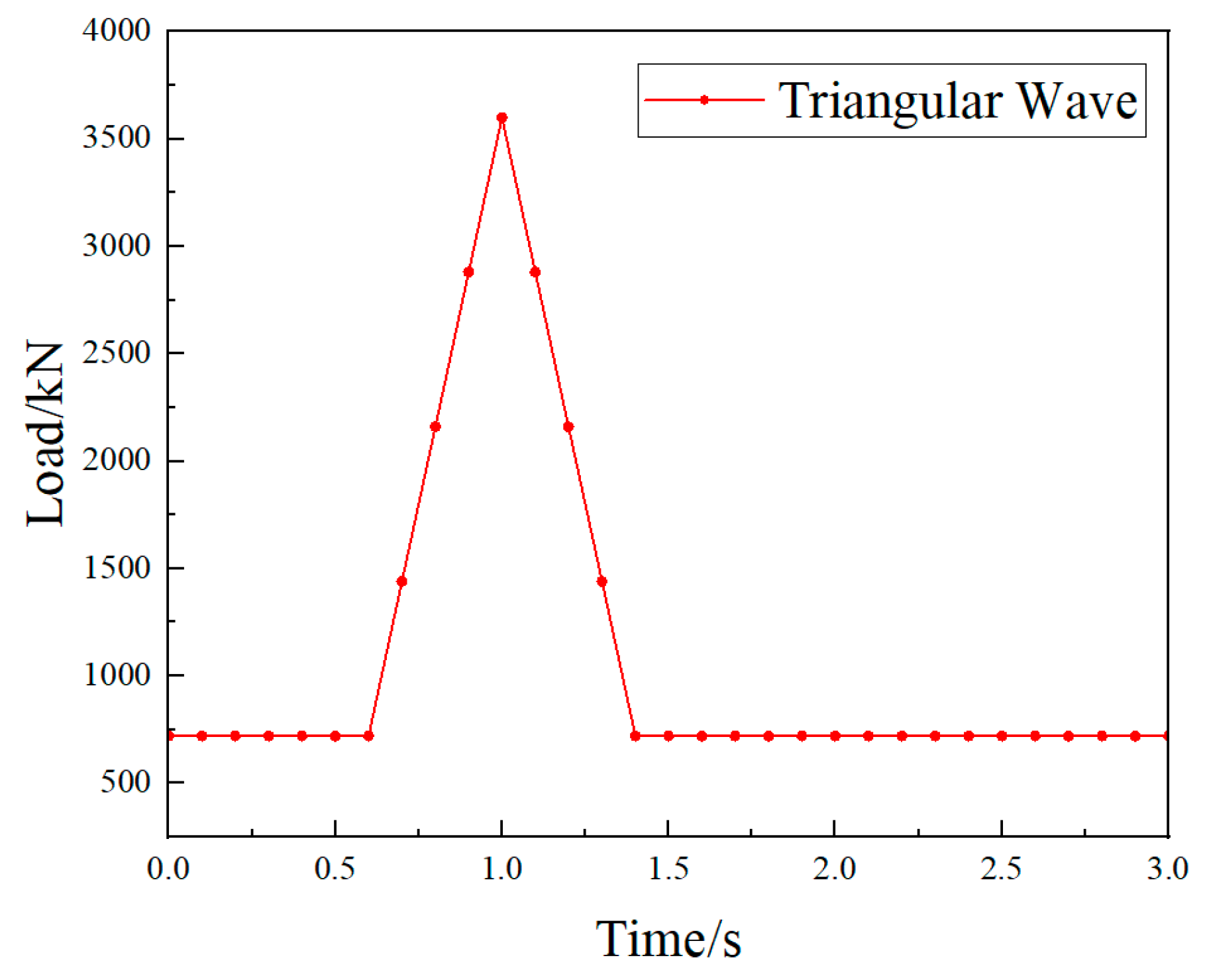
Firstly, a pre-tightening setting is applied to the columns of the hydraulic unit support by imposing 1.5 times the working load. Based on the previously obtained working resistance, the impact load is 3600 kN. In the actual operation of hydraulic supports, short-term impact loads may arise from roof subsidence and pressure. The triangular wave can mimic such impacts well, with its rising and falling edges representing abrupt load application and removal. Its simple shape and clear parameters make it easy to set and adjust in simulations. By defining parameters like peak value, rise time, and fall time, it can flexibly simulate impact loads of varying intensities and durations. In engineering, triangular waves are often used as simplified impact load models, especially in preliminary studies and comparative analyses. They offer conservative estimates, aiding in assessing system performance under extreme conditions. Therefore, this study adopts triangular wave loading, with the load setting shown in
Figure 5. The time for applying the load is set to 3 s.
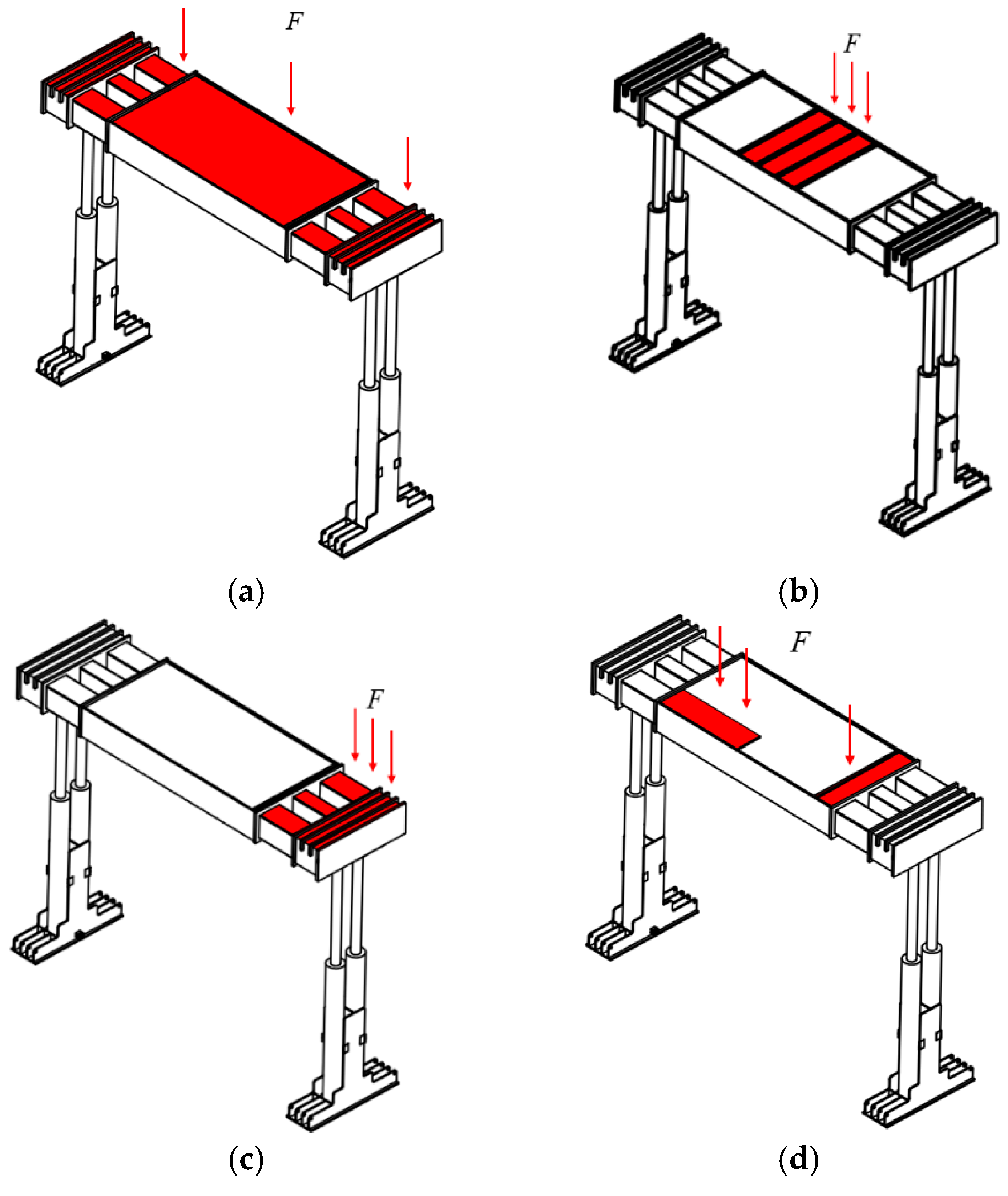
Numerical simulation is utilized to investigate the stress conditions of the support under various loading scenarios, as depicted in
Figure 6.
3.4. Dynamic Simulation Analysis
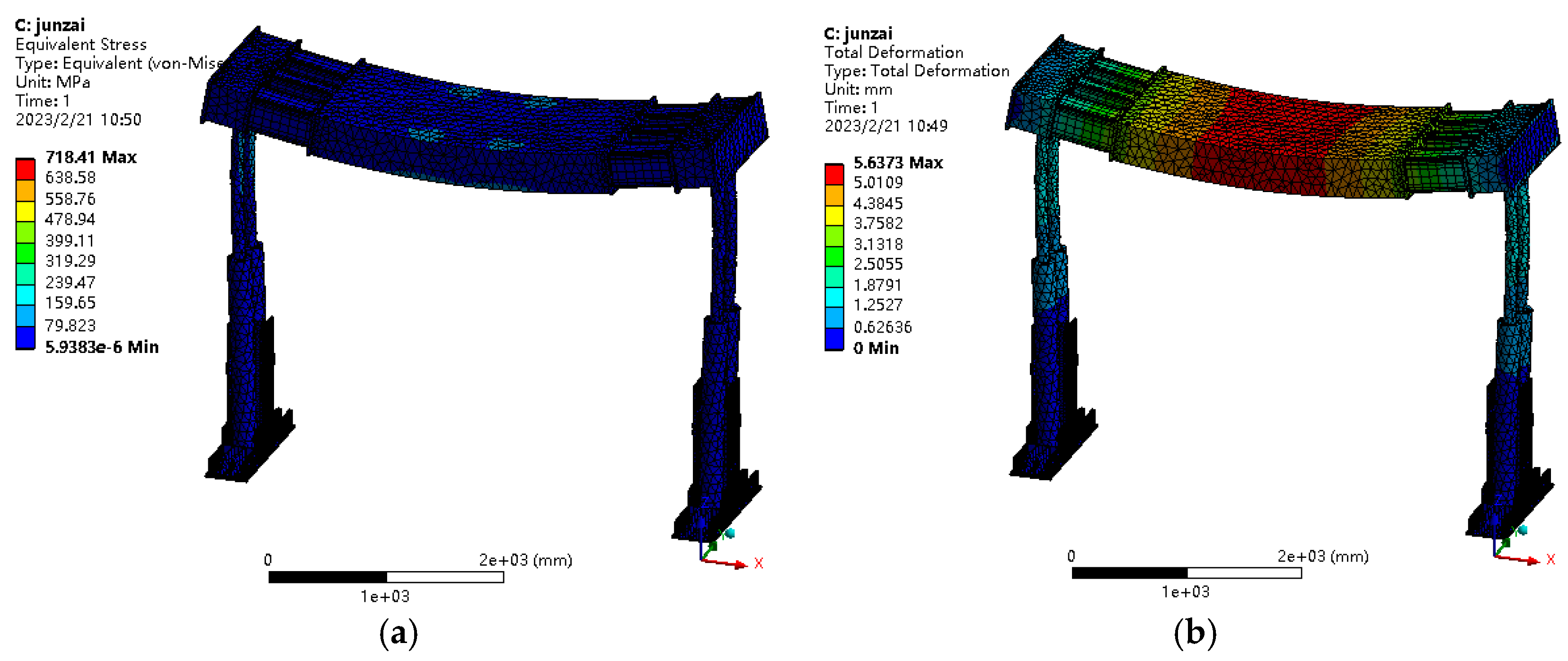
As shown in
Figure 7, when a uniformly distributed impact load is applied to the top beam, the maximum stress rapidly increases to 718.41 MPa, and the maximum displacement value is 5.64 mm. After being subjected to an impact, the top beam exhibits oscillation and quickly returns to a stable condition, with the deformation amount being around 4.26 mm.
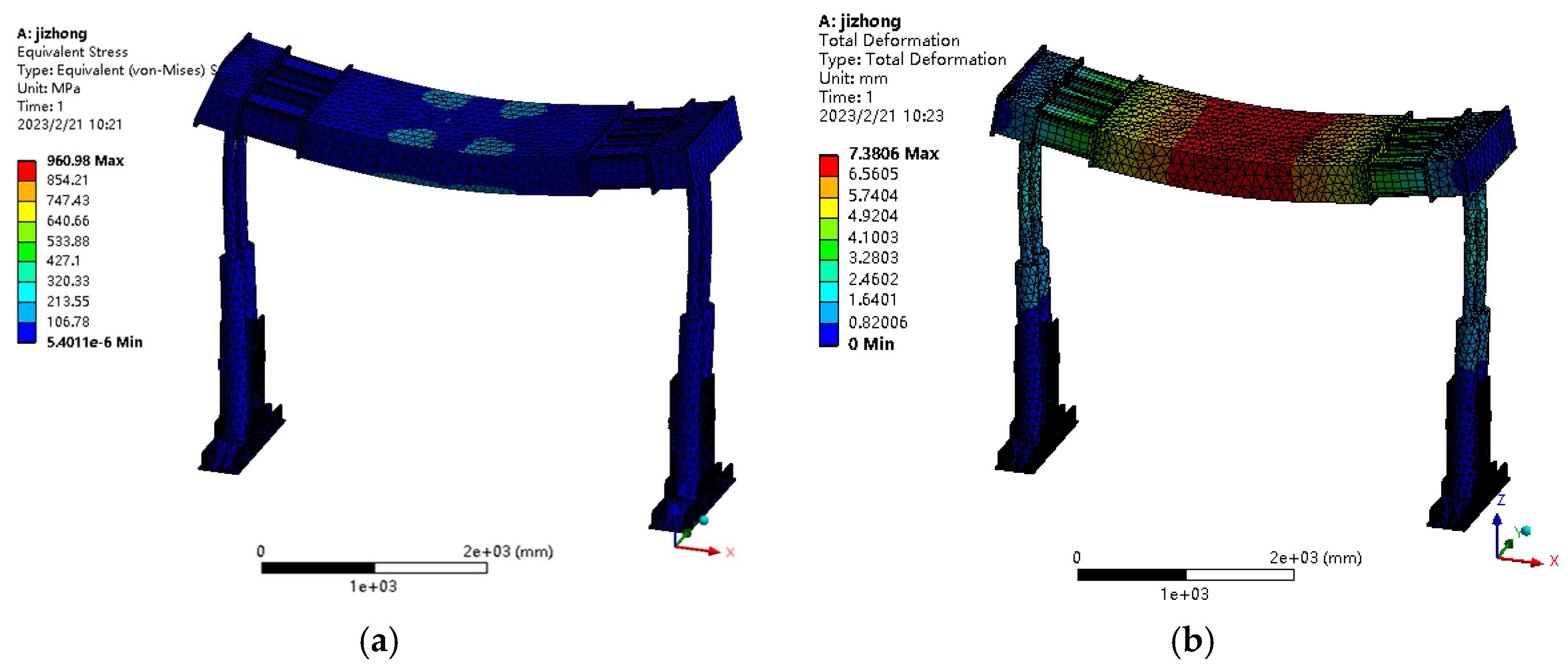
A concentrated load is applied, and a stress variation nephogram of the top beam is shown in
Figure 8a, with the maximum stress on the top beam significantly increasing to 950.98 MPa. Simultaneously, the maximum displacement of the top beam also increases significantly, as shown in
Figure 8b, with the maximum value reaching 7.38 mm. As shown in the above analysis, the maximum deformation of the support complies with the hydraulic support design requirements, so the hydraulic unit support has high reliability in this working condition.
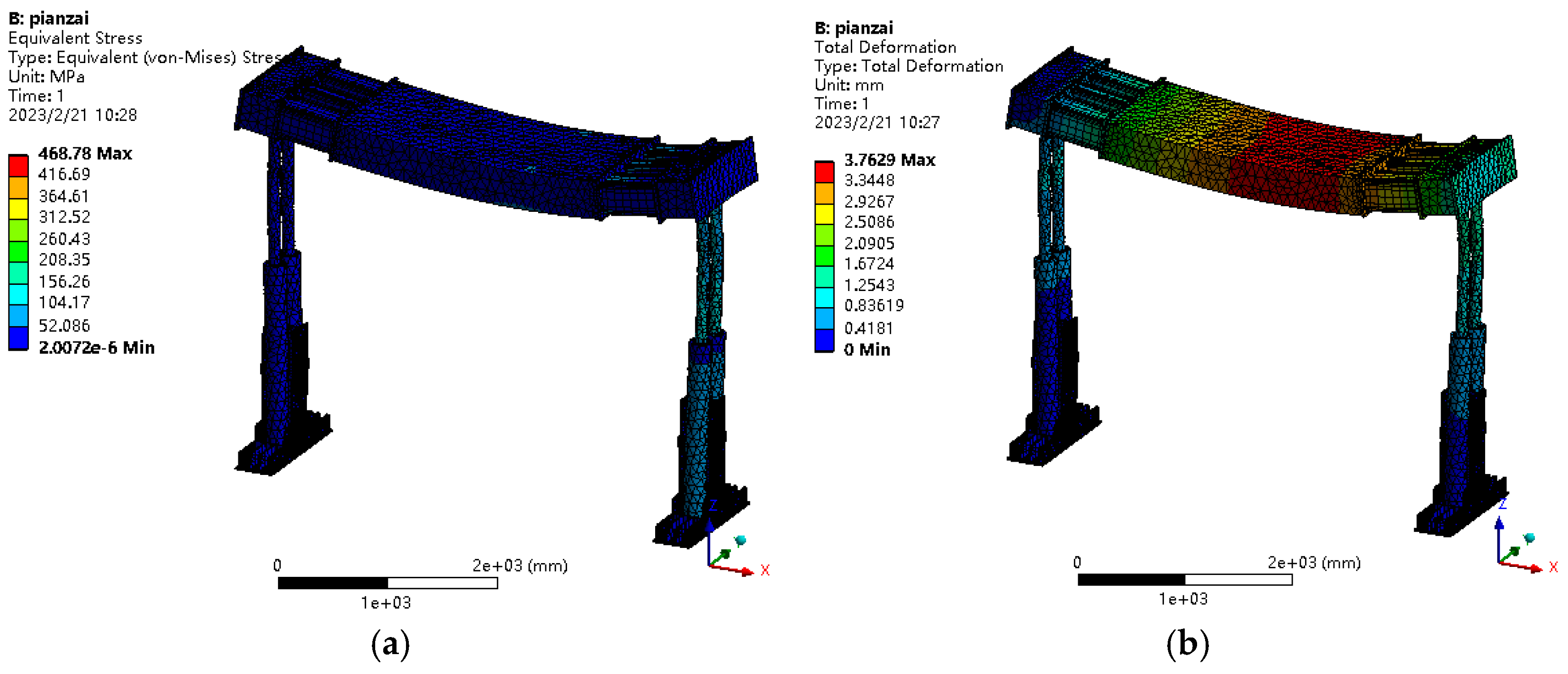
The top beam is subjected to an eccentric impact load, and a stress variation cloud diagram of the top beam is displayed in
Figure 9a. Simultaneously, the maximum displacement value of the top beam also shows a significant decrease, with the maximum value reaching 3.76 mm, as shown in
Figure 9b. The results indicate that the maximum stress induced by the impact load on the side beams is much smaller than that on the intermediate beam, with the maximum stress value reaching 468.78 MPa. When the impact load is applied to the side beam, the maximum stress at the pivot connection between the top beam and the column is 632 MPa.
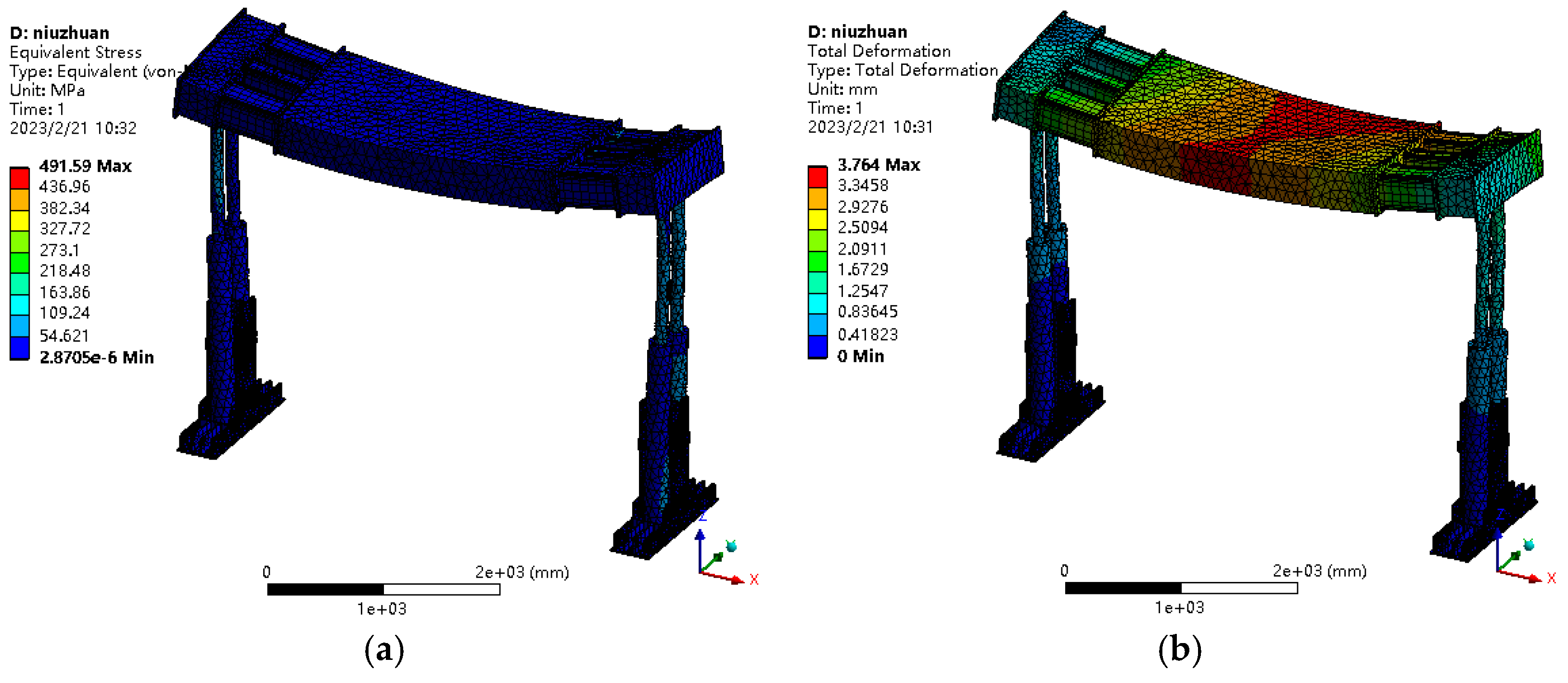
A stress variation cloud diagram of the top beam under torsional load is shown in
Figure 10a, with the maximum stress value reaching 491.59 MPa. The maximum displacement value of the top beam also increases significantly, with the maximum value reaching 3.76 mm, as shown in
Figure 10b. The results indicate that the maximum stress induced on the side beam by the impact load is much lower than that on the intermediate beam. When the load is applied to the side beam, the maximum stress value at the pivot pin connecting the top beam and the column is 328 MPa.
In summary, when the top beam is subjected to concentrated loads, it undergoes maximum stress and deformation. Therefore, the structural strength of the top beam should be a primary consideration in the design of the entire support system. The simulation results indicate that when the intermediate beam and side beams are subjected to the same load impact, the stress and deformation of the intermediate beam are greater than those of the side beams. Therefore, the structural strength of the intermediate beam should be increased.
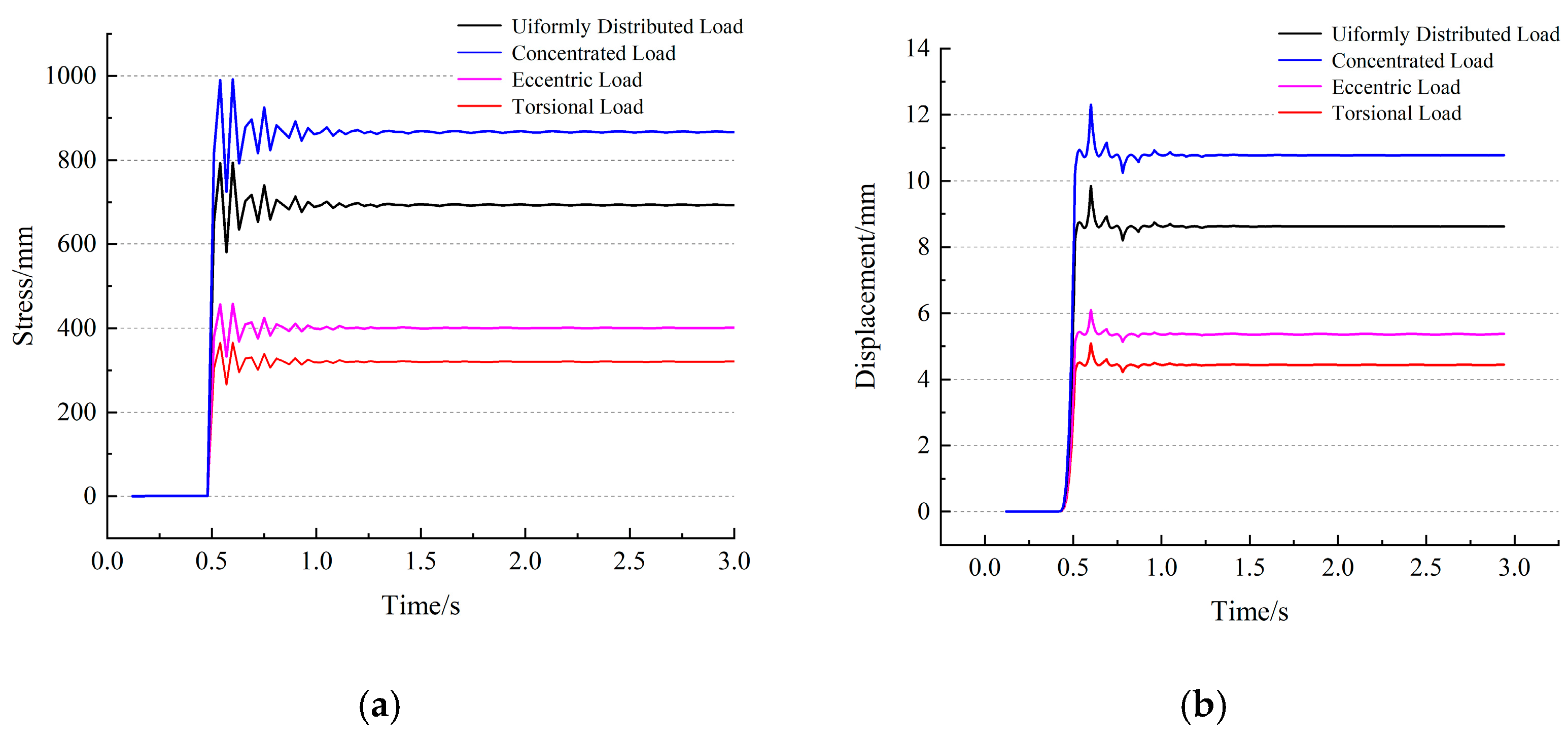
Figure 11 illustrates the stress and displacement of the pivot connection between the top beam and the column of the hydraulic support under the four aforementioned working conditions as the triangular wave impact load is applied, showing the variation over time. From
Figure 11a, it can be seen that the maximum stress occurs at 0.5 s, with a maximum value of 954.0 MPa.
Figure 11b presents the maximum displacement variation curves under different conditions, and it can be observed that the maximum displacement occurs at 0.5 s, with a maximum value of 12.35 mm. Both the maximum stress and maximum displacement closely follow the variation pattern of the triangular impact load. As can be seen from the figure, the pivot connection between the roof beam and the columns of the support is a stress concentration area, which is more prone to deformation than the roof beam itself. Therefore, it is necessary to increase the structural strength at this location.
4. Experimental Study on the Dynamic Performance of Hydraulic Supports
To investigate the dynamic performance of the support, a support performance testing system was constructed. Corresponding to the simulation process, the unit support was simplified, and a prototype of the unit support was fabricated at a 1:3 scale, with the basic parameters of the support prototype.
The dynamic experimental study of the hydraulic unit support coupled with the roof mainly investigates the variation in displacement and pressure parameters at various collection points on the top beam and column cylinders of the hydraulic unit support prototype under the excitation of a hydraulic actuator in a supported state. The sensor layout of this experimental setup is depicted in
Figure 12. Two laser displacement sensors are mounted on an independent wooden support structure, which is anchored to the ground and separate from the experimental platform. Test point 1 is positioned at the base of the intermediate beam, while test point 2 is situated at the base of the side beam. Two pressure transducers are connected in parallel on the pipeline of the support prototype’s columns to separately measure the oil pressure in the rod cavities of the left and right columns of the support prototype.
Since the hydraulic system of this experimental platform shares the same hydraulic power unit, in order to ensure the stability of the support structure, the internal and external loading should be carried out independently when applying loads to the hydraulic support. During loading, the hydraulic unit support is first preloaded. Subsequently, vibration loading is applied to the servo valve.
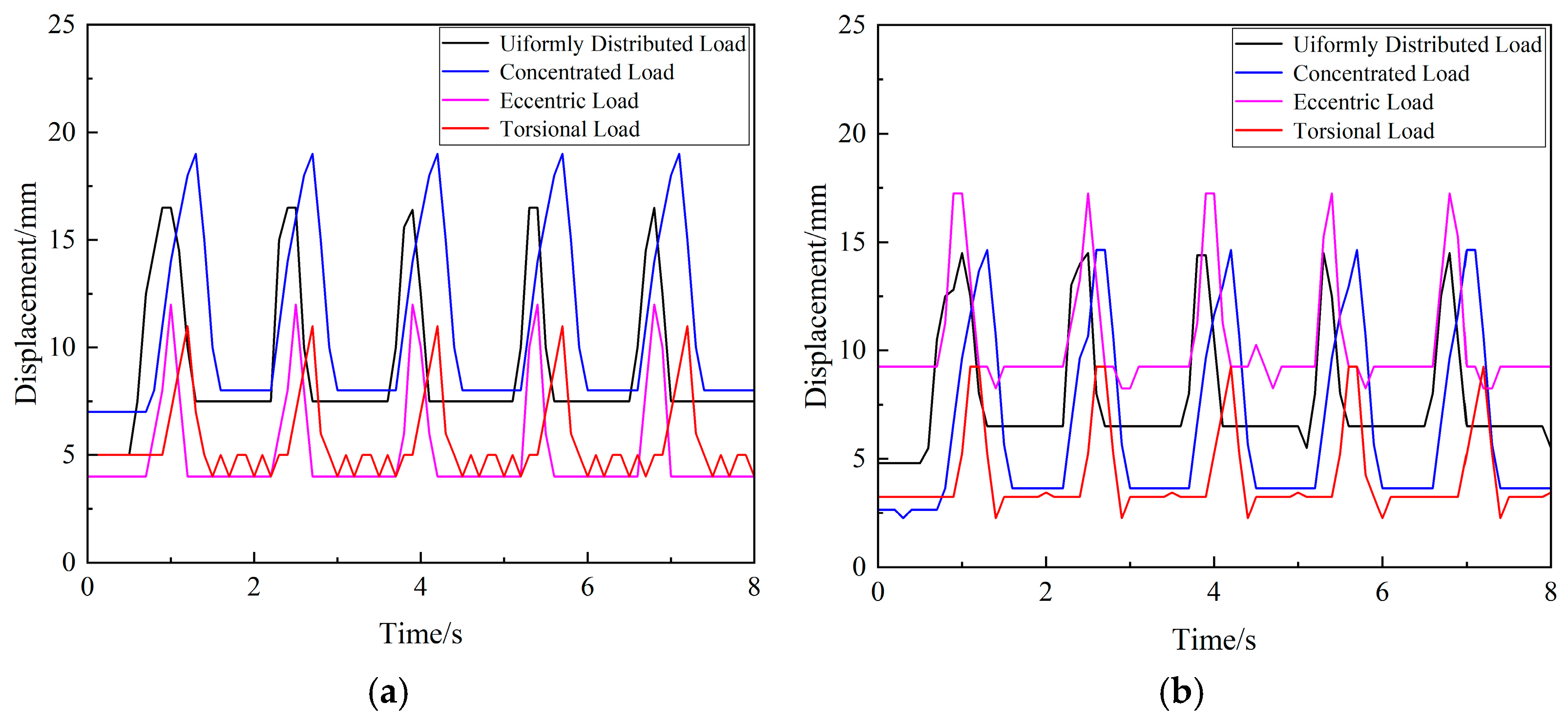
When the support prototype is excited by a uniformly distributed dynamic load, it moves smoothly with relatively low vibration signals. The range of displacement amplitude is 0~20 mm as shown in
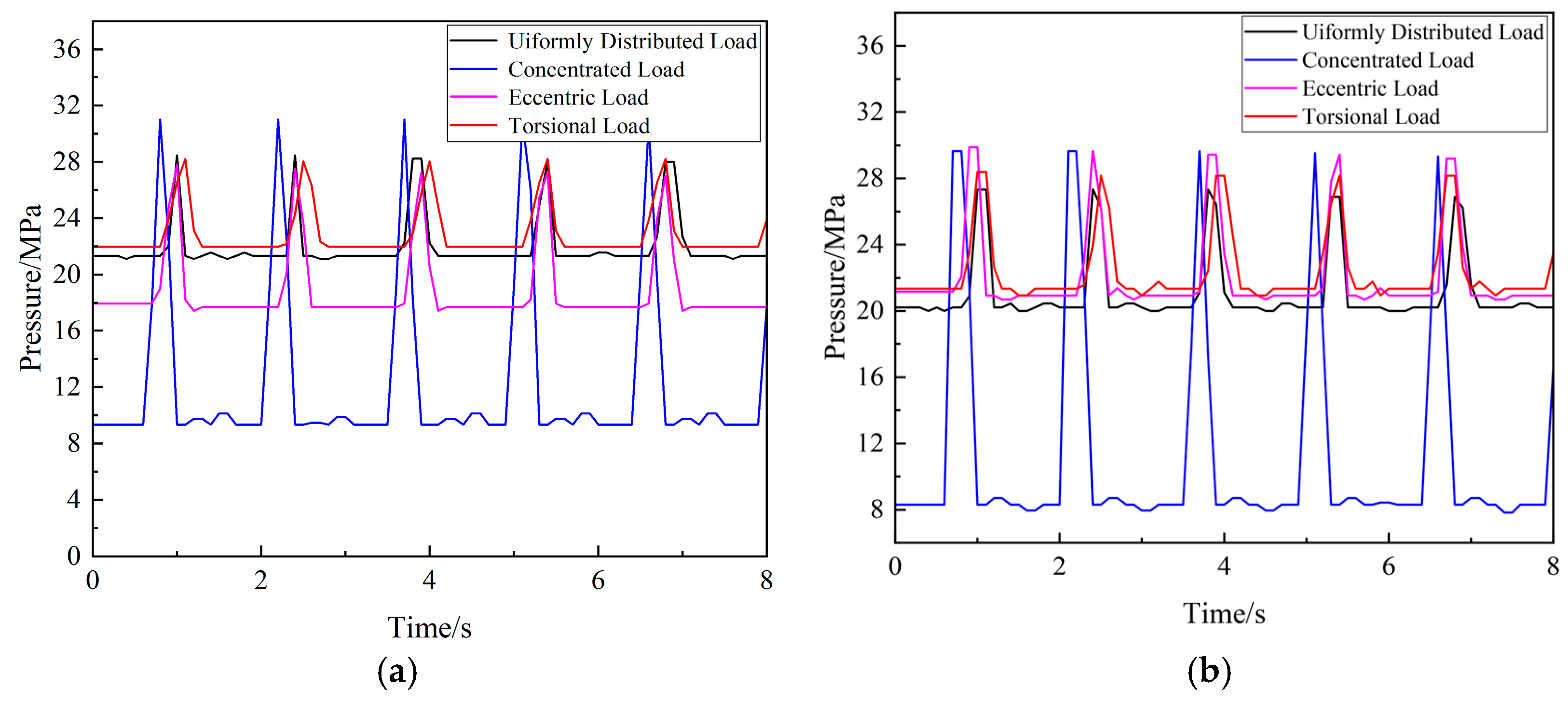
Figure 13, and the range of column oil pressure amplitude is 5~35 MPa, as shown in
Figure 14. When the support prototype is subjected to concentrated dynamic load excitation, the vibration signals are relatively strong. The range of displacement amplitude is 4~17 mm, and the range of column oil pressure amplitude is 20~30 MPa. When the support prototype is excited by dynamic eccentric loads, the vibration signals are pronounced. The range of displacement amplitude is 4~18 mm, and the range of column oil pressure amplitude is 16~30 MPa. When the support prototype is subjected to dynamic torsional load excitation, the vibration signals are relatively weak. The range of displacement amplitude is 2~12 mm, and the range of column oil pressure amplitude is 22~29 MPa.
Differences between experimental and simulation results may stem from several factors. First, hinge joints in practice might be loose or gapped, leading to boundary conditions that do not fully match simulation assumptions. Simulations often presume fully fixed constraints, but actual constraints in experiments may be less rigid. Second, contact nonlinearities can occur in experiments, and geometric nonlinearities at large deformations can significantly impact results, effects that simulations might not account for. These factors can result in discrepancies between the two. However, the overall dynamic response is still favorable, with the dynamic response of the support’s top beam under excitatory loads aligning well with experimental findings. Through comparative experiments, it has been observed that under the influence of dynamic excitation forces, vibration signals at critical parts of the support prototype are pronounced. The results indicate that the hydraulic unit support prototype generates strong vibration signals at the instant of being subjected to excitation loads under various conditions, highlighting significant dynamic issues.
5. Conclusions
1. This study comprehensively analyzed the dynamic characteristics of a new cyclic selfmoving hydraulic combined support’s mechanical parts, focusing on the top beam’s stress and displacement under various impact loads. The results showed that under a uniform load, the top beam’s maximum stress rapidly rose to 718.41 MPa, with a maximum displacement of 5.64 mm. After the impact, the top beam oscillated and stabilized with a deformation of around 4.26 mm. Under a concentrated load, the maximum stress on the top beam significantly increased to 950.98 MPa, and the maximum displacement reached 7.38 mm. For an eccentric load, the top beam’s maximum stress was much smaller on the side beams than on the intermediate beam, with the maximum stress reaching 468.78 MPa. When the load was applied to the side beam, the maximum stress at the hinge connection between the top beam and column was 632 MPa. Under a torsional load, the maximum stress on the top beam was 491.59 MPa, and the maximum displacement was 3.76 mm.
2. From the simulation results, it can be concluded that the intermediate beam experiences greater force and deformation under impact loads compared to the side beams; hence, the structural strength of the intermediate beam should be enhanced. The pivot connection between the top beam and the columns of the support is a stress concentration area, which is more susceptible to deformation than the top beam itself; therefore, the structural strength at this location needs to be increased.
3. This study mainly centered on mechanical component analysis. Future research directions will include modeling the hydraulic system, investigating the interaction between mechanical and hydraulic subsystems, and exploring the integration of other support techniques like micropiles and anchors to further enhance the stability and safety of hydraulic supports.
Author Contributions
All authors contributed to the study’s conception and design. Structural design, theoretical calculation, model building, and analysis were performed by K.W., X.T., B.C., X.C., Q.W. and J.W. The first draft of the manuscript was written by K.W. and all authors commented on previous versions of the manuscript. All authors have read and agreed to the published version of the manuscript.
Funding
This work is supported by the China Postdoctoral Science Foundation (Grant No. 2021M703501) and the Priority Academic Program Development of Jiangsu Higher Education Institution (PAPD).
Institutional Review Board Statement
Not applicable.
Informed Consent Statement
Not applicable.
Data Availability Statement
The data will be made available upon request.
Conflicts of Interest
The authors declare that they have no known competing financial interests or personal relationships that could have appeared to influence the work reported in this paper.
References
- Ding, K.; Wang, L.; Tian, J.; Ren, B.; Jiang, C.; Wang, S. Design of a Highly Adaptable Advance Support for a Deep, Fully Mechanized Roadway and Analysis of Its Support Performance. Appl. Sci. 2022, 12, 12728. [Google Scholar] [CrossRef]
- Chang, S.; Ye, M.; Zhang, D.; Ma, Y.; Zhang, J. Impact Performance Optimization for Hydraulic Rock Drill Based on Stroke and Flow Compensation Factors. Adv. Mech. Eng. 2024, 16, 16878132241259579. [Google Scholar] [CrossRef]
- Meng, Z.S.; Ma, C.; Xie, Y.Y. Influence of Impact Load Form on Dynamic Response of Chock-Shield Support. Eksploat. I Niezawodn.-Maint. Reliab. 2023, 25, 168316. [Google Scholar] [CrossRef]
- Xie, Y.; Zeng, Q.; Jiang, K.; Meng, Z.; Li, Q.; Zhang, J. Investigation of Dynamic Behaviour of Four-Leg Hydraulic Support under Double-Impact Load. Stroj. Vestn.-J. Mech. Eng. 2022, 68, 385–394. [Google Scholar] [CrossRef]
- Pytlik, A. Process Characteristics of Hydraulic Legs Equipped with Safety Valves at Dynamic Load Caused by Mining Tremor. Arch. Min. Sci. 2015, 60, 595–612. [Google Scholar] [CrossRef]
- Chen, H.; Chen, H.; Xu, Y.; Zhang, D.; Ma, Y.; Mao, J. Research on Attitude Monitoring Method of Advanced Hydraulic Support Based on Multi-Sensor Fusion. Measurement 2022, 187, 110341. [Google Scholar] [CrossRef]
- Wang, D.L.; Zeng, X.T.; Wang, G.F.; Li, R. Adaptability Analysis of Four-Leg Hydraulic Support with Large Mining Height under Impact Dynamic Load. Shock Vib. 2022, 2022, 2168871. [Google Scholar] [CrossRef]
- Szurgacz, D.; Brodny, J. Adapting the Powered Roof Support to Diverse Mining and Geological Conditions. Energies 2020, 13, 405. [Google Scholar] [CrossRef]
- Zhai, G.D.; Yang, X. Modelling and Analysis of a Hydraulic Support Prop Under Impact Load. J. S. Afr. Inst. Min. Metall. 2022, 122, 397–405. [Google Scholar] [CrossRef]
- Cao, L.; Jin, X.; Qin, J.; Zhang, X.; Gao, L. Research on the Hydraulic Support Top Beam Based on Dynamic Load Bearing. Front. Earth Sci. 2023, 11, 1171342. [Google Scholar] [CrossRef]
- Yang, Z.K.; Sun, Z.Y.; Jiang, S.B.; Mao, Q.H.; Liu, P.; Xu, C.Z. Structural Analysis on Impact-Mechanical Properties of Ultra-High Hydraulic Support. Int. J. Simul. Model. 2020, 19, 17–28. [Google Scholar] [CrossRef]
- Guo, J.; Huang, W.; Feng, G.; Bai, J.; Li, L.; Wang, Z.; Yu, L.; Wen, X.; Zhang, J.; Feng, W. Stability Analysis of Longwall Top-Coal Caving Face in Extra-Thick Coal Seams Based on an Innovative Numerical Hydraulic Support Model. Int. J. Min. Sci. Technol. 2024, 34, 491–505. [Google Scholar] [CrossRef]
- Zeng, Q.; Li, Z.; Wan, L.; Ma, D. Study on Roof Instability Effect and Bearing Characteristics of Hydraulic Support in Longwall Top Coal Caving. Appl. Sci. 2023, 13, 8102. [Google Scholar] [CrossRef]
- Song, W.; Yu, S.; Rong, H.; Jiao, H.; Xu, X. Study on the Characteristic of Overburden Rock Structure and Support System of the Retraction Channel in Layered Fully Mechanized Caving Face. Sci. Rep. 2024, 14, 1360. [Google Scholar] [CrossRef]
- Fang, Z.; Geng, C.Z. Study on the Dynamic Characteristics and Parameter Identification of Elastic Hydraulic Isolator in Floating Slab Track System. J. Mech. Sci. Technol. 2024, 38, 1719–1729. [Google Scholar] [CrossRef]
- Zhu, Y.P.; Zeng, Q.H.; Wan, L.; Yang, Y.R.; Li, Z. Vibration Response Difference of Caving Mechanism Under Coal Rock Impact Based on Mechanical-Hydraulic Coupling. Sci. Rep. 2023, 13, 13794. [Google Scholar] [CrossRef]
- Swiatek, J.; Janoszek, T.; Cichy, T.; Stoinski, K. Computational Fluid Dynamics Simulations for Investigation of the Damage Causes in Safety Elements of Powered Roof Supports—A Case Study. Energies 2021, 14, 1027. [Google Scholar] [CrossRef]
- Hu, J.; Li, Y.; Jiang, P.; Zhao, L. Architectural Design and Robust Optimization of Adaptive Hydraulic Engine Mount. J. Braz. Soc. Mech. Sci. Eng. 2024, 46, 128. [Google Scholar] [CrossRef]
- Rajwa, S.; Janoszek, T.; Prusek, S. Model Tests of the Effect of Active Roof Support on the Working Stability of a Longwall. Comput. Geotech. 2020, 118, 103302. [Google Scholar] [CrossRef]
- Meng, Z.S.; Zhang, J.M.; Xie, Y.Y.; Lu, Z.G.; Zeng, Q.L. Analysis of the Force Response of a Double-Canopy Hydraulic Support Under Impact Loads. Int. J. Simul. Model. 2021, 20, 766–777. [Google Scholar] [CrossRef]
- Cao, L.; Xu, Y.; He, C.; Zhang, E.; Miao, Y. Analysis of the Load-Bearing Characteristics of Hydraulic Supports for Top-Coal Caving Under the Impact of Coal and Gangue. Energy Sci. Eng. 2024, 12, 4810–4822. [Google Scholar] [CrossRef]
- Wan, L.R.; Yu, X.H.; Ma, D.J.; Meng, Z.S.; Zeng, Q.L.; Qi, G.Q. Dynamic Response Analysis of a Novel Anti-Impact Pressure Balance Jack. Energies 2022, 15, 5236. [Google Scholar] [CrossRef]
- Guan, E.G.; Miao, H.H.; Li, P.B.; Liu, J.H.; Zhao, Y.Z. Dynamic Model Analysis of Hydraulic Support. Adv. Mech. Eng. 2019, 11, 1687814018820143. [Google Scholar] [CrossRef]
- Ren, H.W.; Zhang, D.S.; Gong, S.X.; Zhou, K.; Xi, C.Y.; He, M.; Li, T.J. Dynamic Impact Experiment and Response Characteristics Analysis for 1:2 Reduced-Scale Model of Hydraulic Support. Int. J. Min. Sci. Technol. 2021, 31, 347–356. [Google Scholar] [CrossRef]
- Mu, M.; Xie, B.; Yang, Y. Research on Attitude Analysis of Hydraulic Support Based on Column Length. Stroj. Vestn.-J. Mech. Eng. 2024, 70, 293–310. [Google Scholar] [CrossRef]
- Jin, Z.; Xu, Y.; Peng, T.; Gao, L. Roof Control Technology of Mining Roadway Under the Influence of Advanced Supporting Pressure. Adv. Civ. Eng. 2021, 2021, 2049755. [Google Scholar] [CrossRef]
- Xie, B.W.; Yang, Y. Study on Working Characteristics of 4-Column Hydraulic Support in Lifting-Lowering-Moving State Based on Microcontact Theory and Rigid-Flexible-Mechanical-Hydraulic Coupling Simulation Model. Actuators 2024, 13, 193. [Google Scholar] [CrossRef]
- Kuang, B.; Wang, X.; Hou, J.; Hu, W. Studying Dynamical and Hydraulic Characteristics of the Hydraulically Suspended Passive Shutdown Subassembly (HS-PSS) and Validating with a Prototypic Test Sample. Energies 2024, 17, 5038. [Google Scholar] [CrossRef]
- Liu, Y.H.; Guan, X.; Lu, P.P.; Guo, R. Simulation Research on Dynamic Characteristics of Hydraulic Mount. Chin. J. Mech. Eng. 2021, 34, 49. [Google Scholar] [CrossRef]
- Du, Z.; Qin, B.; Tian, F. Numerical Analysis of the Effects of Rock Bolts on Stress Redistribution Around a Roadway. Int. J. Min. Sci. Technol. 2016, 26, 975–980. [Google Scholar] [CrossRef]
- Chen, X.; Tian, X.; Wu, K. Research on Bearing Characteristics of Hydraulic Unit Support under Impact Load. Coal Mine Mach. 2023, 44, 45–48. [Google Scholar] [CrossRef]
| Disclaimer/Publisher’s Note: The statements, opinions and data contained in all publications are solely those of the individual author(s) and contributor(s) and not of MDPI and/or the editor(s). MDPI and/or the editor(s) disclaim responsibility for any injury to people or property resulting from any ideas, methods, instructions or products referred to in the content. |
© 2025 by the authors. Licensee MDPI, Basel, Switzerland. This article is an open access article distributed under the terms and conditions of the Creative Commons Attribution (CC BY) license (https://creativecommons.org/licenses/by/4.0/).


