Article

Theoretical Approach for Micro-Settlement Control in Super-Large Cross-Section Tunnels Under Sensitive Environments

1
School of Civil Engineering, Beijing Jiaotong University, Beijing 100044, China
2
China Railway Construction Co., Ltd., Beijing 410082, China
*
Author to whom correspondence should be addressed.
Appl. Sci. 2025, 15(8), 4375; https://doi.org/10.3390/app15084375
Submission received: 14 February 2025 / Revised: 28 March 2025 / Accepted: 29 March 2025 / Published: 15 April 2025

Abstract

:
The rapid development of urban transportation renovation and transportation networks in China has driven the construction of an increasing number of large-span, large cross-section tunnels under sensitive environments, such as airport runways, critical infrastructure, and high-speed railways. These projects often require strict settlement control within a millimeter-level tolerance range, thus theoretical methods and key technologies for micro-settlement control have been developed. This study first derives a calculation formula for surface settlement associated with large cross-section tunnels and elucidates its correlations with factors such as pipe-roof stiffness, support system stiffness, pipe-roof construction procedures, and groundwater level changes. Theoretical approaches for controlling micro-settlement are introduced, including increasing pipe-roof stiffness, reinforcing the support system, mitigating group pipe effects, maintaining pressure and reducing resistance around the pipe, and controlling groundwater levels. A method is proposed for determining the appropriate stiffness of the pipe roof and support system. The stiffness should be selected from the transition segment between the steep decline and the gentle slope on the stiffness-settlement curves of the pipe roof and the support system. If the stiffness of the pipe roof and primary support combined with temporary support fails to meet the micro-settlement control requirements, an integrated support system with greater stiffness can be adopted. A reasonable pressure-regulating grouting technique for maintaining pressure and reducing resistance around the pipe is proposed. It is recommended that the spacing for simultaneous jacking of pipes be greater than half the width of the settlement trough. For over-consolidation-sensitive strata such as medium or coarse sands, water-blocking measures, including freezing, grouting, or a combination of both, are recommended. For over-consolidation-insensitive strata like gravels and cobbles with strong permeability, water-blocking treatments are generally unnecessary. The proposed theoretical approaches have been successfully implemented in projects such as the tunnel beneath Beijing Capital Airport runways and Taiyuan Railway Station, demonstrating their reliability. The research findings provide valuable insights into surface micro-settlement control for similar projects.

1. Introduction

With the rapid expansion of urban transportation renovation and transportation networks in China, a growing number of large-span, large cross-section tunnels are being constructed beneath sensitive environments, including airport runways, critical infrastructure, and high-speed railways. These projects often demand stringent settlement control within millimeter-level tolerances, underscoring the need to advance theoretical approaches and key techniques for micro-settlement control.
Numerous researchers around the world have investigated settlement control for tunnels beneath sensitive environments through theoretical analysis, numerical simulations, and physical model tests. These studies evaluate the effectiveness of various surface settlement control measures, including enhancing support stiffness, optimizing pipe-roof construction, and managing groundwater levels. Chen [1] performed finite element numerical simulations to analyze the impact of support timing and primary support strength on surrounding rock deformation and surface settlement during shallow tunnel excavation. Dai et al. [2] optimized the original support scheme of “single-layer steel arch primary support + double-layer secondary lining” through numerical simulations and field monitoring. This optimization effectively controlled the surrounding rock deformation and reduced the stress on the secondary lining. Guo et al. [3] conducted a safety performance optimization analysis of support design parameters for a three-lane, large cross-section highway tunnel under construction in Guangdong Province. This analysis took into account factors such as surrounding rock conditions, burial depth, tunnel shape, and cross-section dimensions. Zhan [4] modified the Peck formula [5] to account for construction-induced stress and ground loss, enabling more accurate predictions of surface settlement during pipe-jacking operations. Gong et al. [6] applied random medium theory to evaluate surface settlement resulting from curved pipe jacking construction in ultra-shallow drainage layers. Sun et al. [7] utilized numerical simulations to analyze the patterns of soil displacement around the pipe-roof structures and surface settlement during pipe-roof construction in soft soils. Ji et al. [8] conducted three-dimensional numerical simulations to examine the interactions and effects of closely spaced multi-pipe-jacking operations on soil deformation and surface settlement. They concluded that multi-pipe-jacking construction produced a cumulative effect on the settlement trough. Yang Xian et al. [9] investigated the impact of densely arranged, large-diameter steel pipe installations on the surface settlement in the pipe-roof pre-construction method. They further analyzed the impact of completed steel pipes at different intervals on the surface settlement during subsequent pipe-roof operations. Yang et al. [10] proposed a water level variation curve and a flow-around zone division formula through model experiments. Furthermore, they developed a simplified calculation method for surface settlement outside the foundation pit, which was further modified using the seepage principles within the flow-around zone. Wu [11] partitioned the soil layers in the dewatering area into distinct zones and calculated the settlement of each zone using the layerwise summation method, thereby determining the total surface settlement. Wen [12] investigated the stress variations in the surrounding rock of a karst tunnel under seepage conditions and proposed a method for calculating surface settlement in the soil-surrounding rock section under these circumstances. Gu et al. [13] studied the consolidation compression of soil units in dewatering areas based on the effective stress principle and one-dimensional consolidation compression theory. They also predicted the surface settlement around the foundation pit using the stochastic medium theory method. Tan et al. [14] developed an ultra-long large pipe-roof construction technique for the Capital Airport runway tunnel. This approach incorporated pressure-maintained grouting around the pipe, automatic micro-adjustment technique for the micro shield machine, and pipe-roof pre-support around the tunnel, which collectively addressed the issue of pavement settlement control. Liu et al. [15] investigated the surface settlement patterns and interactions between closely spaced circumferential pipes during pipe-jacking operations for the Gongbei Tunnel, a segment of the Zhuhai Link for the Hong Kong-Zhuhai-Macao Bridge. Wang [16] examined the factors affecting settlement in the Yingze Street underpass project beneath the Taiyuan Station and proposed a comprehensive settlement control technique tailored to the construction process. Tan et al. [17] conducted model tests to investigate the effects of different pipe-roof layouts, pipe diameters, and excavation methods on surface settlement and pipe-roof behavior. Aghajari et al. [18] optimized the sequential excavation method for controlling ground settlement in the tunnel of Tehran Metro Line 6. Morovatdar et al. [19] analyzed the effect of pipe characteristics in the umbrella arch method on controlling tunneling-induced settlements in soft grounds. Hakeri et al. [20] analyzed the effects of important factors on surface settlement prediction for metro tunnels excavated by EPB. The tunnel boring machine has played a very good role in controlling surface settlement [21,22].
At present, most researchers have only analyzed the law of surface subsidence in a single process, and there is a lack of systematic analysis of multiple factors such as pipe curtain stiffness, support stiffness, pipe curtain construction, and groundwater subsidence. There is also a lack of research on the entire process of surface subsidence, and no systematic theoretical methods have been formed. Based on large cross-section tunnel projects beneath the Capital Airport runway and Taiyuan Railway Station, this study develops a theoretical formula to predict surface settlement. The derived formula establishes the relationship between surface settlement and factors such as pipe-roof stiffness, support system stiffness, pipe-roof construction procedures, and groundwater level changes. Additionally, micro-settlement control techniques are proposed and their effectiveness is validated through real-world engineering applications.

2. Calculation Method for Surface Settlement

2.1. Overview

When an extra-large cross-section tunnel passes beneath airport runways, railway embankments, and other critical structures in sensitive environments, the settlement control standards are extremely stringent, typically requiring millimeter-level micro-settlement. Micro-settlement control for such tunnels typically involves advanced pipe-roof support and sequential excavation methods.
Surface settlements caused by tunnel construction under pipe-roof protection can be classified into three main components: surface settlement due to tunnel excavation (u1), surface settlement caused by pipe-roof installation (u2), and surface settlement resulting from groundwater level drawdown (u3). Assuming the soil is an average soil and without considering the rheological effects between the three types of settlement. The total surface settlement can be calculated using Equation (1).
u = u 1 + u 2 + u 3
The surface settlement caused by tunnel excavation comprises transverse and longitudinal components. The transverse settlement arises from flexural deformation caused by insufficient primary support stiffness, with the maximum typically occurring near the tunnel centerline. The longitudinal settlement results from bending deformation due to inadequate pipe-roof stiffness, with the maximum generally located near the tunnel face. The surface settlement resulting from pipe-roof installation consists of ground loss during the installation of individual pipes and additional settlement due to the superimposed effects of group pipe construction. Changes in groundwater levels alter the effective stress within the soil, thereby causing over-consolidation settlement in the strata. The extent of this settlement varies significantly across different strata.

2.2. Surface Settlement from Tunnel Excavation (u1)

When an extra-large cross-section tunnel passes beneath airport runways, railway embankments, and
The following assumptions are made: the overburden load on the tunnel is considered to be the self-weight of the soil and is evenly distributed; the lateral pressure is assumed to be uniformly distributed; and the surface settlement is equal to the settlement at the tunnel vault.
(1)
Calculation of transverse settlement in tunnel
The tunnel primary support with a unit width is assumed to be a frame structure. The bottom is modeled as an elastic foundation beam, while the top and sides are subjected to earth pressure. The calculation model is depicted in Figure 1.
The bending differential equation is established as follows:
d 2 y ( x ) d x 2 = q 2 E 1 I 1 ( a x x 2 ) λ q b 2 2
where q is the overburden load on the tunnel; E1I1 is the primary support stiffness; a is the tunnel width; b is the tunnel height; λ is the lateral pressure coefficient.
Integrating Equation (2) and applying the boundary conditions yields:
y ( x ) = q 24 E 1 I 1 ( a 3 x 2 a x 3 + x 4 ) + λ q b 2 4 E 1 I 1 ( x 2 a x )
Substituting x = a/2 into Equation (3) to obtain the maximum deflection:
u 1 C r o s s s e c t i o n = q E 1 I 1 5 a 4 384 λ a 2 b 2 16
The load from the unclosed primary support section is shared equally by the soil in front of the tunnel face and the closed primary support structure. The calculation model is illustrated in Figure 2.
The calculation and analysis demonstrate that the influence range of the load transferred from the pipe roof to the primary support and the surrounding rock in front of the tunnel face is approximately 5 m. The additional load applied to the primary support with a unit width is 0.1γhL. Therefore, there is q = γh + 0.1γhL.
u 1 C r o s s s e c t i o n = γ h E 1 I 1 1 + L 10 × 5 a 4 384 λ a 2 b 2 16
where L is the distance from the tunnel face to the closed primary support structure.
If temporary supports are installed in the tunnel, they can be considered as an enhancement to the stiffness of the primary support. The calculation formula for the equivalent stiffness is as follows:
E I = 1 + 3 n E 1 I 1 a 3 k 1 × E 1 I 1
where EI is the equivalent stiffness of temporary and primary supports; n is the number of vertical temporary supports; k1 is the stiffness of temporary support, which is calculated using the column stability method with the formula k1 = (3E3I3)/b3, where E3I3 is the stiffness of vertical temporary supports.
(2)
Calculation of longitudinal settlement in tunnel
Figure 2 illustrates the mechanical calculation model of the pipe roof along the tunnel’s longitudinal direction, where the additional load applied to the soil per unit width is expressed as 0.1γhL.
Based on the Winkler hypothesis, the soil settlement at the tunnel face can be calculated using Equation (7):
u 1 a h e a d = γ h 10 k
where γ is the unit weight of the soil; h is the tunnel depth; k is the elastic resistance coefficient of the soil.
The pipe roof in the unclosed primary support section is assumed to be a beam with both ends fixed. Based on this assumption, the maximum deflection can be calculated as follows:
u 1 d e f l e c t i o n = γ h L 4 384 E 2 I 2
u 1 l o n g i t u d i n a l   p r o f i l e = γ h 10 k + γ h L 4 384 E 2 I 2
where E2I2 denotes the stiffness of the pipe roof.
The settlement caused by tunnel excavation is the sum of longitudinal and transverse settlements, which can be determined using Equation (10):
u 1 = γ h E 1 I 1 1 + L 10 5 a 4 384 λ a 2 b 2 16 + γ h 10 k + γ h L 4 384 E 2 I 2

2.3. Surface Settlement Induced by Pipe Roof Construction (u2)

First, the surface settlement caused by the jacking of a single pipe is calculated, followed by the determination of surface settlement induced by the superimposed effect of adjacent pipe jacking.
(1)
Surface settlement induced by single-pipe construction
The mechanical calculation model for a single pipe constructed using a micro shield machine is illustrated in Figure 3.
The surface settlement resulting from single-pipe construction is determined using the Peck formula:
s x = A V i 2 π e x 2 2 i 2
where s(x) is the surface settlement calculated by the Peck formula; V is the ground loss ratio; x is the distance from the tunnel centerline; i is the distance from the symmetrical center of the settlement trough to the inflection point; A is the excavation area, A = πr2.
V = 4 w r w 2 4 r 2
where w is the maximum settlement at the pipe crown caused by single-pipe construction; r is the radius of the pipe roof.
Since the vault settlement w is much smaller than r, V can be simplified as follows:
V w r
i = H 2 π tan 45 o φ 2
where H is the depth of the pipe roof; c is the cohesion; φ is the internal friction angle.
The Levy-Mises theory describes the plastic flow laws of ideal elastic-plastic materials:
d ε i j p = d λ · f σ i j
where d ε i j p is the increment of plastic strain, d λ is the plastic multiplier, f is the yield function (here, the Hoek-Brown criterion is used). The Hoek-Brown criterion describes rock mass strength:
σ 1 = σ 3 + σ c m σ 3 σ c + s a
where σ 1 and σ 3 are the principal stresses, σ c is the uniaxial compressive strength of the rock, m, s, and a are parameters related to the Geological Strength Index (GSI).
Assuming that pipe jacking is an axisymmetric problem, the axial stress and radial stress satisfy the equilibrium equations:
d σ r d r + σ r σ θ r = 0
By substituting the Hoek-Brown criterion into the equilibrium equations and introducing the von Mises flow rule, we obtain:
d σ r d r = β r σ r p 0 α 1 / α
where α and β are coefficients related to the Hoek-Brown parameters and material properties. By integrating using the separation of variables method, the expression for radial displacement ww is obtained:
w = 3 α r 2 G 1 3 α p p 0 + β / 3 α 1 3 α 3 α · p 0 + β 3 α 1 3 α
where p is the grouting pressure; G is the shear modulus of the soil; p0 is the earth pressure, p0 = γH; and since the burial depth is small.
Substituting Equation (19) into Equation (13) and further into Equation (11) yields the maximum surface settlement value at x = 0:
u 2 s i n g l e   p i p e = 1 3 α p p 0 + β / 3 α 1 3 α 3 α · 3 π r 2 α 2 i 2 π G
(2)
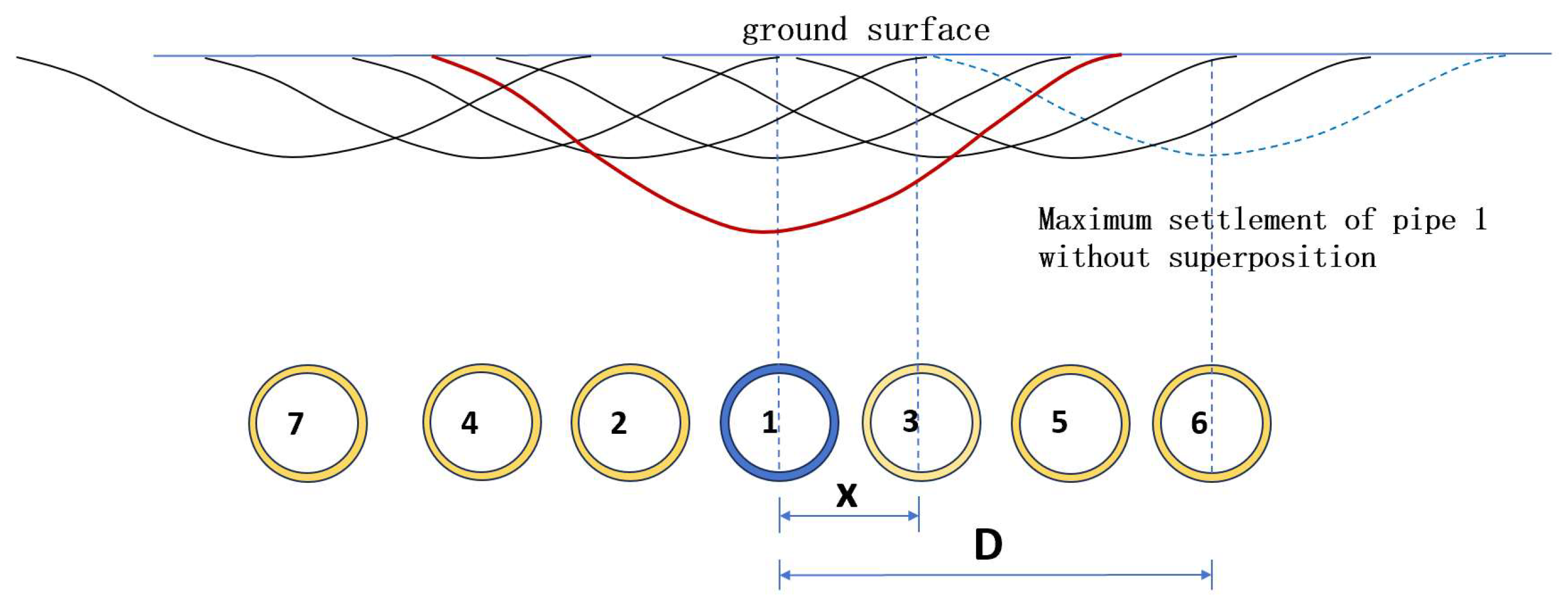
Surface settlement caused by the construction of multiple pipes
The surface settlement caused by the superposition of multiple pipes is expressed as:
u 2 = f ( x ) · u 2 s i n g l e   p i p e
where f(x) is the surface settlement correction coefficient, and its calculation formula is as follows:
f x = 1 + M 1 x λ i
where x is the horizontal distance between the centerlines of two jacked pipes; M is the maximum surface settlement correction coefficient; and λ is generally assigned a value of either 2.5 or 3.
M = 2 R λ i x ( λ i x )
If the horizontal distance x between the centerlines of two jacked pipes surpasses the λi, the maximum surface settlement caused by the construction of the second jacked pipe is not affected by the construction of the first jacked pipe. In this case, M is taken as 0. The surface settlement correction function for the jacking construction of the n-th pipe (n ≥ 2), influenced by the soil disturbance from the previously jacked (n − 1) pipes, is expressed as:
u 2 = j = 1 n f j x · u 2 s i n g l e   p i p e = f 1 x + + f n x · u 2 s i n g l e   p i p e
Consequently, the total surface settlement resulting from the superposition of jacked multiple pipes is:
u 2 = j = 1 n 1 + M 1 x j i × 3 π r 2 α 2 i 2 π G × 1 3 α p p 0 + β / 3 α 1 3 α 3 α

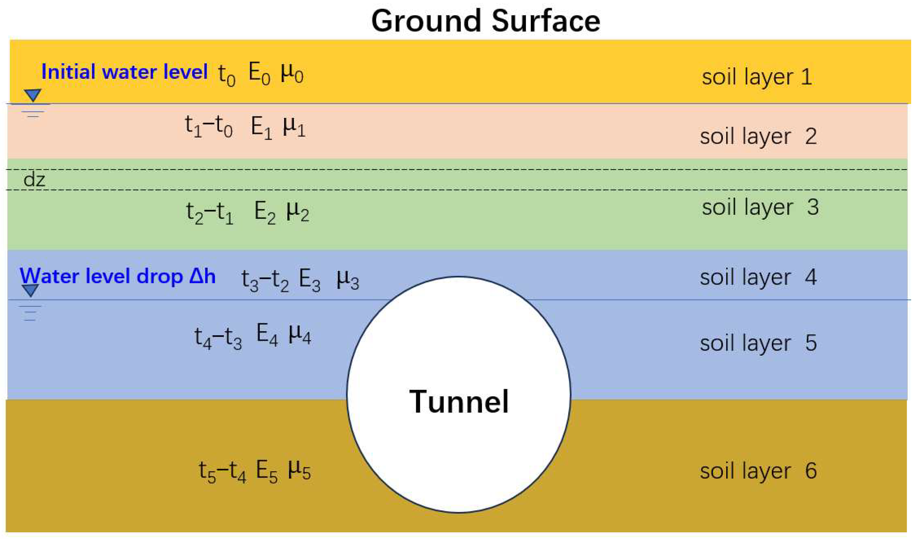
2.4. Surface Settlement Induced by Groundwater Level Drawdown (u3)

Groundwater loss during tunnel construction leads to a decline in the groundwater level, which induces surface settlement due to soil over-consolidation. The settlement calculation model is illustrated in Figure 4.
For the over-consolidation settlement in a single-layer soil, the settlement ds of a unit element is determined by taking dz∈(t0,t0 + t1) as follows:
d s = ε d z = Δ P 01 E s 1 d z
where ds is the settlement of a unit element; ΔP01 is the change in effective stress in the first soil layer caused by groundwater level changes, Δ P 01 = γ w ( z t 0 ) ; Es1 is the compression modulus of the i-th soil layer, E s 1 = 1 μ 1 μ 1 2 E 01 ( 1 μ 1 ) .
The settlement in the first soil layer is obtained through integration:
s 1 = t 0 t 0 + t 1 γ w ( z t 0 ) ( 1 μ 1 μ 1 2 ) E 01 ( 1 μ 1 ) d z = γ w ( 1 μ 1 μ 1 2 ) t 1 2 2 E 01 ( 1 μ 1 )
where μ1 is the Poisson’s ratio of the first soil layer; E01 is the elastic modulus of the first soil layer; and γ w is the unit weight of water.
Similarly, the settlements of the i-th and n-th soil layers can be calculated.
s i = γ w ( 1 μ i μ i 2 ) ( t 1 + + t i ) 2 ( t 1 + + t i 1 ) 2 2 E 0 i ( 1 μ i )
s n = γ w ( 1 μ i μ i 2 ) ( Δ h t n + t n 2 2 ) E 0 i ( 1 μ i )
where Δh is the height of the groundwater level drawdown,μi is the Poisson’s ratio of the i-th soil layer; E0i is the elastic modulus of the i-th soil layer; and ti is the thickness of the i-th soil layer.
For the i-th soil layer, the constant term bi is expressed as:
b i = γ w ( 1 μ i μ i 2 ) E 0 i ( 1 μ i )
The total over-consolidation settlement for n soil layers is obtained by summing the over-consolidation settlements of each individual soil layer.
u 3 = i = 1 n s i = b n ( Δ h t n + t n 2 2 ) + b 1 t 1 2 2 + 1 2 i = 2 n 1 b i ( t 1 + + t i ) 2 ( t 1 + + t i 1 ) 2
where b i = γ w ( 1 μ i μ i 2 ) E 0 i ( 1 μ i ) , and n is the number of soil layers. If the groundwater level is located at the ground surface and the drawdown only affects a single soil layer (n = 1), only the first term of the formula is considered. If the groundwater level is below the ground surface and the drawdown only impacts a single soil layer (n = 2), only the first term of the formula is considered. If the groundwater level is below the ground surface and the drawdown influences multiple soil layers (n > 2), all three terms of the formula are taken into account.

2.5. Total Surface Settlement

The surface settlement induced by the sequential excavation of a large-section tunnel under pipe-roof protection consists of three components: settlement due to tunnel excavation (u1), settlement caused by pipe-roof construction (u2), and settlement induced by groundwater level drawdown (u3). The total surface settlement can be calculated using Equation (32):
u = γ h E 1 I 1 ψ 1 + γ h E 2 I 2 ψ 2 + γ h 10 k + ψ 3 ψ 4 + b n t n Δ h + ψ 5 ψ 1 = 1 + L 10 5 a 4 384 λ a 2 b 2 16 ψ 2 = L 4 384 ψ 3 = 1 3 α p p 0 + β / 3 α 1 3 α 3 α ψ 4 = j = 1 n 1 + M 1 x j i × 3 π r 2 α 2 i 2 π G ψ 5 = b 1 t 1 2 2 + 1 2 i = 2 n 1 b i ( t 1 + + t i ) 2 ( t 1 + + t i 1 ) 2

3. Micro-Settlement Control Techniques

According to Equation (32), the surface micro-settlement caused by the construction of an ultra-large cross-section tunnel under pipe-roof protection mainly consists of three components: settlement induced by pipe-roof construction, settlement caused by tunnel excavation, and settlement resulting from groundwater level drawdown. Key techniques to mitigate micro-settlement include increasing pipe roof stiffness, strengthening the support system, mitigating group pipe effects, maintaining pressure and reducing resistance around the pipe, and controlling groundwater levels. For strata where the groundwater level is below the tunnel floor or where its drawdown does not affect surface settlement, changes in construction and groundwater levels can be ignored.

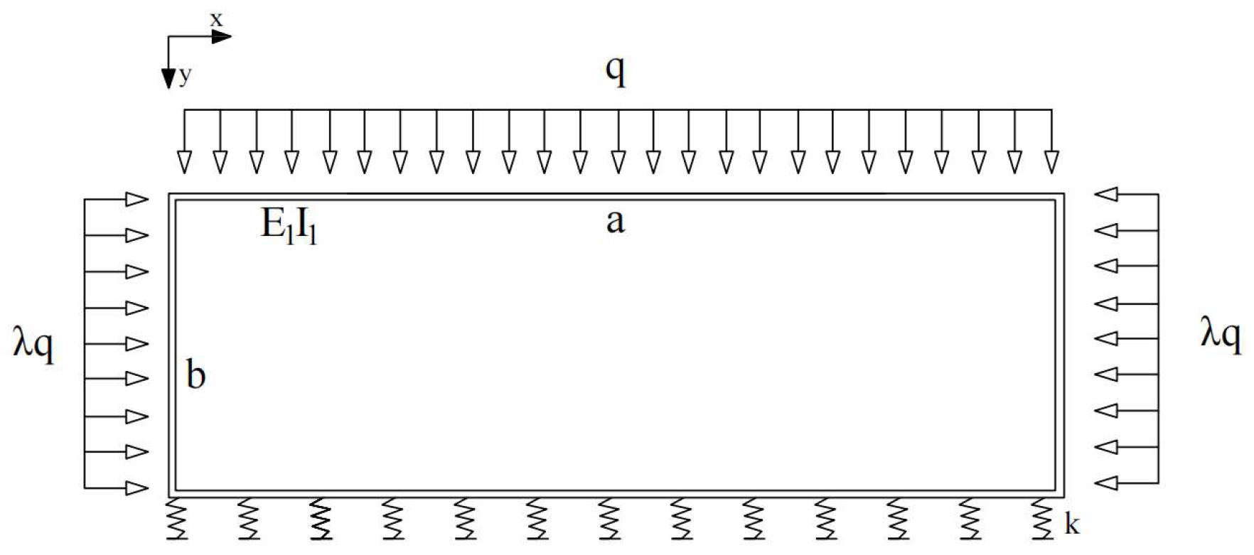
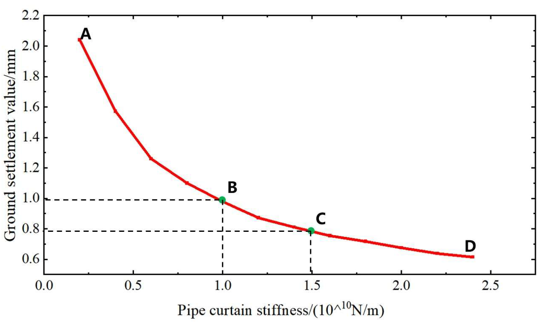
3.1. Method for Determining the Appropriate Pipe Roof Stiffness

As noted in Reference [17], settlement trends observed in experiments using rectangular and gate-shaped pipe roofs were generally consistent. However, surface settlement in the gate-shaped pipe roof tests was 50.8% greater than that in the rectangular pipe roof tests. Therefore, selecting a rectangular cross-section design is essential for controlling surface micro-settlement during large-section tunnel construction.
The pipe roof stiffness is one of the primary factors influencing surface settlement caused by tunnel excavation. To better understand surface settlement patterns, the concept of the load-to-pipe roof stiffness ratio (β = load/stiffness) is introduced. According to Equation (9), the relationship curve between the load-to-pipe roof stiffness ratio β and the longitudinal surface settlement u1 is depicted in Figure 5. Based on specific settlement control standards and load conditions, the pipe roof stiffness is preliminarily determined, and Figure 6 depicts the relationship curve between surface settlement and pipe roof stiffness. The curve AB represents the sharp descent segment, indicating that an increase in pipe roof stiffness significantly reduces the surface settlement. The curve BC represents the transition segment between a steep descent and a gentle slope, where the pipe roof stiffness is both effective in controlling settlement and cost-efficient. Therefore, the pipe roof stiffness should be designed to fall within this range. The curve CD represents the gentle slope segment, indicating that an increase in pipe roof stiffness has minimal effect on surface settlement control. If the preliminarily determined pipe roof stiffness falls within the BC range, it is deemed reasonable; otherwise, adjustments should be made to bring it into this range.

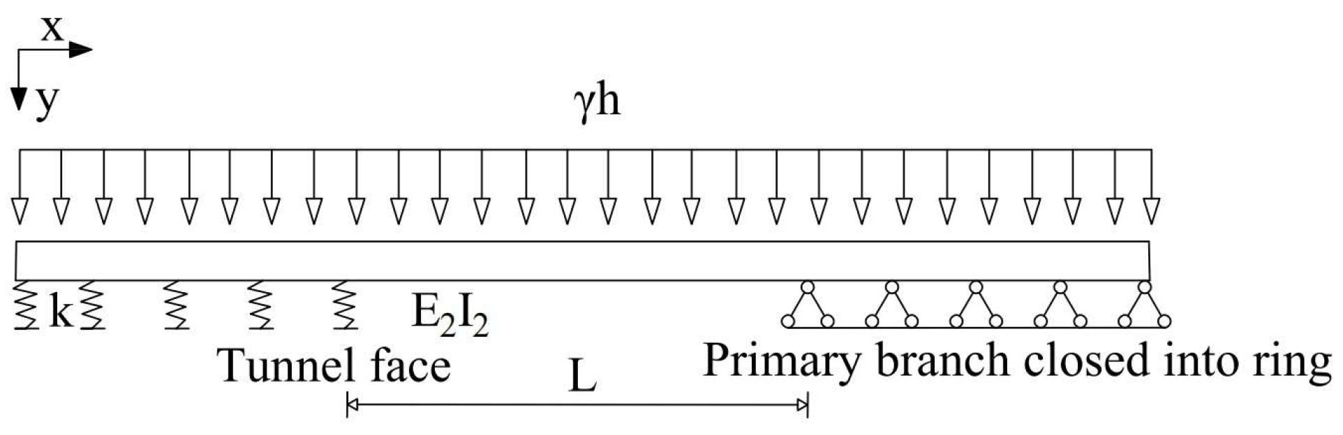
3.2. Method for Determining the Appropriate Support System
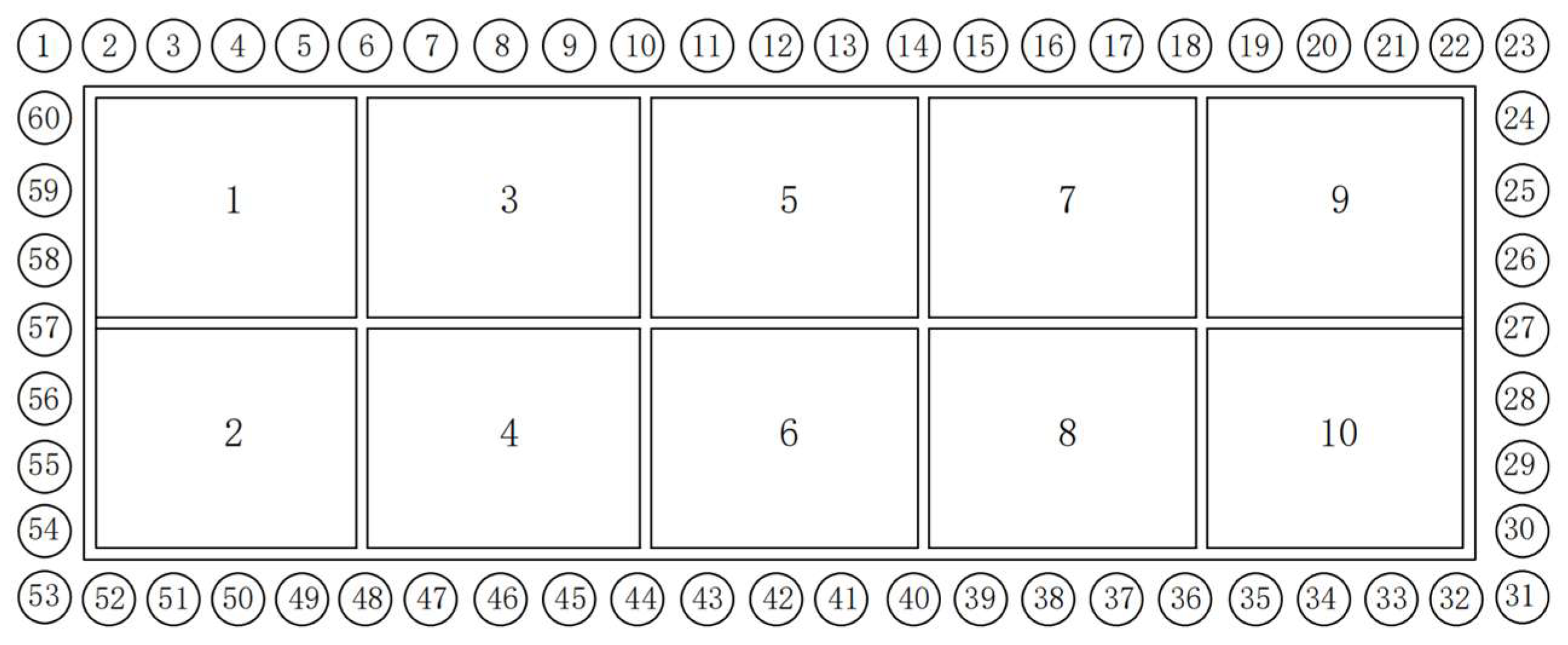
(1)
Main forms of support systems
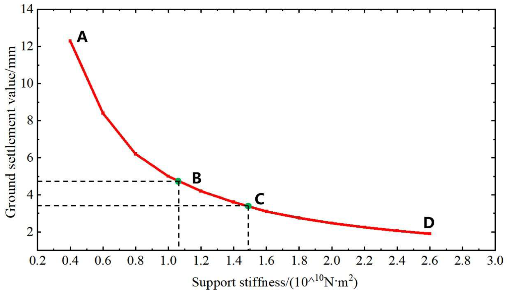
The stiffness of the support system must be sufficiently high to control surface micro-settlement during the construction of large cross-section tunnels. The main forms of high-stiffness support systems include high-stiffness primary support, primary support combined with temporary support, and integrated support structure. As the tunnel span increases, the stiffness of the primary support alone often fails to meet micro-settlement control requirements. This necessitates the use of temporary supports to enhance stiffness, as illustrated in Figure 7. The number of the blocks represents the order of excavation.
In highly sensitive environments with stricter settlement control requirements, where pipe roofs combined with primary and temporary supports fail to meet the requirements, an integrated support system can be adopted. This system integrates the pipe roof, primary support, and secondary lining into a unified high-stiffness structure. This approach involves circumferentially cutting the pipe roof to create interconnected spaces, followed by constructing a reinforced concrete structure to effectively control surface settlement caused by tunnel excavation.
(2)
Determining the appropriate stiffness of the support system
The stiffness of the support system is one of the critical factors affecting surface settlement caused by tunnel excavation. To better understand settlement patterns, a relationship curve between the load-to-support system stiffness ratio (β) and the transverse surface settlement (u1) is established based on Equation (4), as presented in Figure 8. Based on specific settlement control standards and load conditions, the stiffness of the support system is preliminarily determined, and Figure 9 illustrates the relationship curve between surface settlement and support system stiffness. The curve AB represents the sharp descent segment, indicating that an increase in support system stiffness significantly reduces the surface settlement. The curve BC represents the transition segment between a sharp descent to a gentle slope, where the support system stiffness is both effective in controlling settlement and cost-efficient. Therefore, the stiffness of the support system should be designed to fall within this range. The curve CD represents the gentle slope segment, indicating that an increase in support system stiffness has minimal effect on surface settlement control. If the preliminarily determined support system stiffness falls within the BC range, it is deemed reasonable; otherwise, adjustments should be made to bring it into this range.

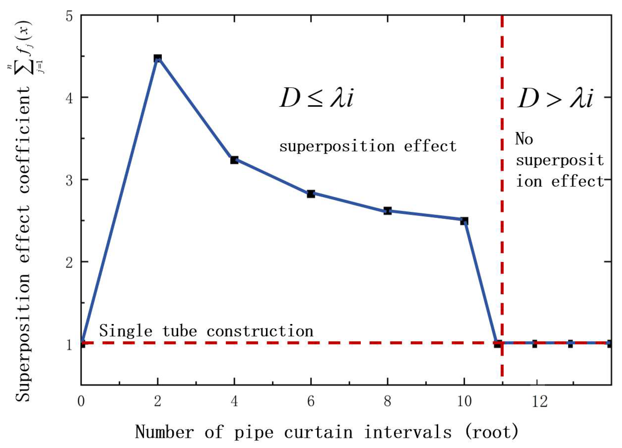
3.3. Techniques for Reducing the Settlement Superimposition Effect Induced by Group Pipe Construction

Sequential construction of individual pipes during the tunnel pipe-roofing process can effectively minimize the deformation superimposition effect but inevitably extend the construction period. In contrast, simultaneous construction of multiple pipes can shorten the construction period; however, it may cause a greater deformation superimposition effect, resulting in a significant increase in surface settlement. To accelerate construction progress and control surface settlement, a simultaneous alternate pipe jacking method is employed for pipe-roof construction, and the interval number of jacked pipes is reasonably determined based on the width of the surface settlement trough. According to Equation (22), the interval number of jacked pipes is multiplied by the designed pipe spacing to calculate xj, which is then utilized to determine the group pipe superimposition coefficient, as illustrated in Figure 10. If the pipe spacing exceeds a critical value, the settlement troughs of adjacent pipes are no longer superimposed.
As illustrated in Figure 11, the pipe roof construction sequence begins with the simultaneous installation of pipes No. 1, No. 6, and No. 7, during which no settlement trough superimposition occurs among the group pipes. After these pipes are installed, pipes No. 2 and No. 5 are constructed, followed by pipes No. 3 and No. 4. This rational construction sequence effectively mitigates the group pipe superimposition effect, thereby minimizing overall surface settlement.

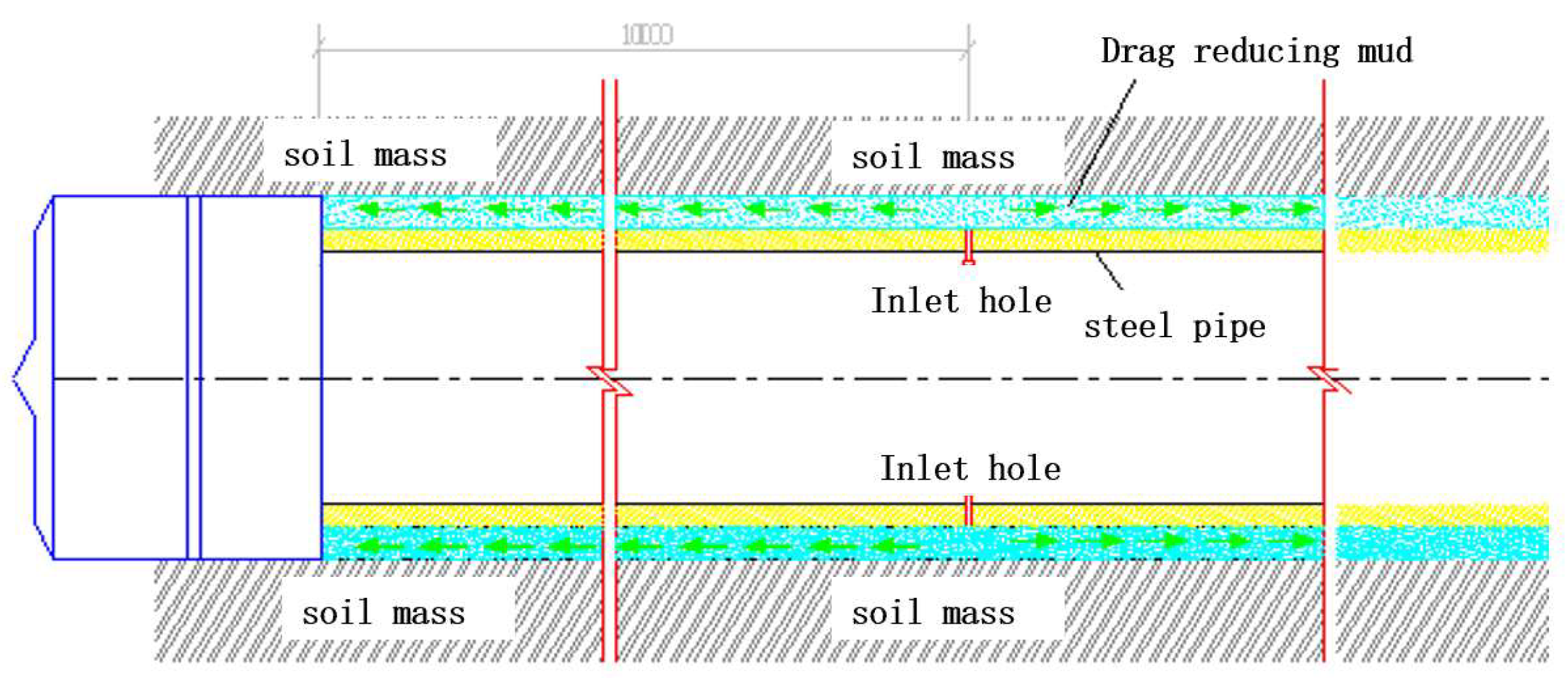
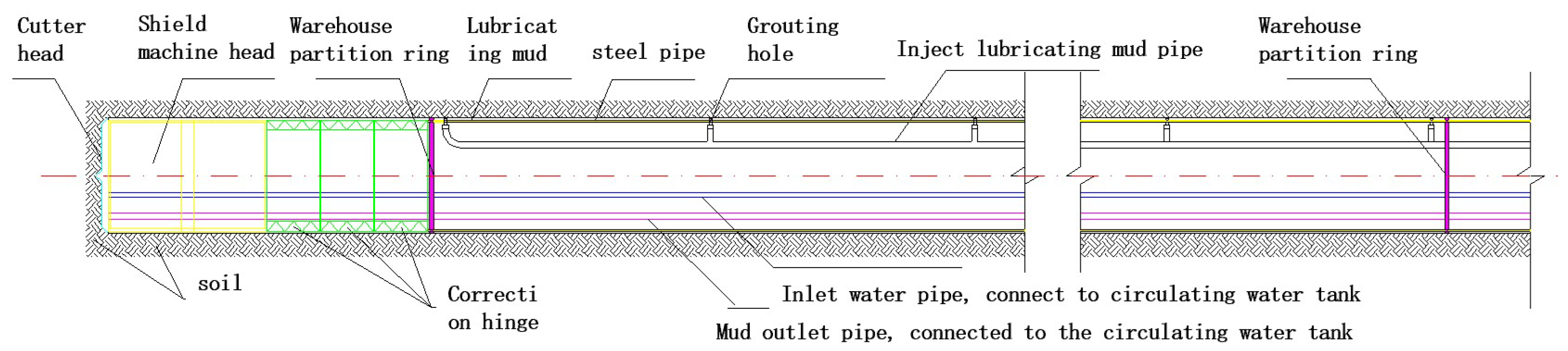
3.4. Grouting Pressure Maintenance Technique Around the Pipe During the Pipe-Roof Jacking Process

To control surface settlement caused by the construction of individual pipes in the pipe roof, the grouting pressure must be carefully regulated to achieve saturation grouting pressure. Proper regulation prevents excessive settlement due to insufficient low pressure and surface heaving due to excessive pressure. The relationship between grouting pressure and surface settlement, as derived from Equation (20), is illustrated in Figure 12.
Figure 13 illustrates the relationship between pipe spacing and surface settlement under different grouting pressures. As the pipe spacing increases, the impact of subsequent pipe installations on the first pipe gradually decreases. When the pipe spacing exceeds λi = 15.996 m, the influence of subsequent pipe installations outside the settlement trough on the first pipe becomes negligible. Meanwhile, an increase in grouting pressure alters the surface settlement behavior. Specifically, the initial settlement decreases, followed by surface heaving, with the heaving magnitude gradually increasing. The minimum surface settlement is observed at a grouting pressure of 0.28 MPa, indicating that this pressure represents a reasonable grouting pressure. Therefore, selecting an appropriate grouting pressure ensures that the surface settlement remains within a relatively small range.
The pipe-roof jacking must possess functions such as portal pressure maintenance, lubrication and pressure maintenance around the pipe, and synchronous grouting. To achieve this, a device for maintaining portal pressure and a system for lubrication and pressure maintenance around the pipe were developed, as illustrated in Figure 14. During soil excavation using a micro shield machine, the cutter head’s diameter is larger than that of the steel pipe, thus creating a gap that significantly contributes to settlement during the pipe jacking process. To address this issue, grout is uniformly injected at a constant pressure to stabilize the borehole walls and prevent collapse and settlement. Additionally, it serves as a lubricant to reduce resistance. To maintain pressure and reduce resistance around the pipe, a lubrication slurry pipeline system is installed within the pipe, along with a nozzle system evenly distributed around the pipe wall. These components together form an ultra-long slurry jacket, which reduces resistance on the outer surface of the steel pipes in the pipe roof.
A longitudinal main grouting pipeline, which runs the entire length of the steel pipe within the pipe roof, is installed internally and connected to circumferential branch pipelines via three-way valves. To prevent abrupt pressure loss in the lubrication chamber due to cracks or voids in the soil, compartmentalized partition rings are installed at regular intervals along the steel pipe, as depicted in Figure 15.

3.5. Groundwater Level Control Techniques

Tunnel construction often results in groundwater loss and a subsequent drop in groundwater levels, causing soil layers to undergo over-consolidation settlement. According to Equation (31), the degree of over-consolidation settlement depends on soil properties and the height of the groundwater level drawdown. Therefore, over-consolidation settlement curves are calculated for different soil types and specific groundwater control measures are proposed as follows:
(1)
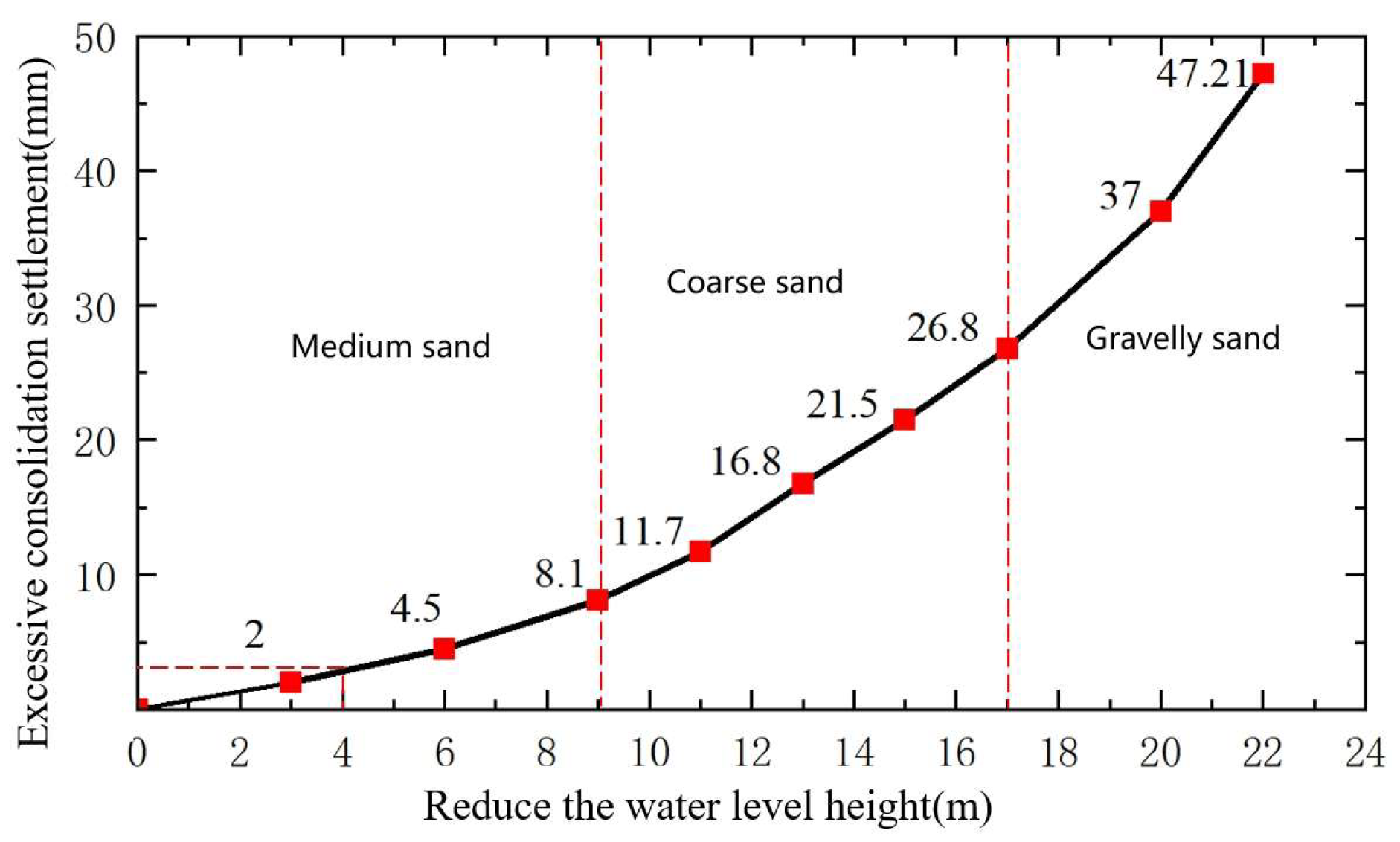
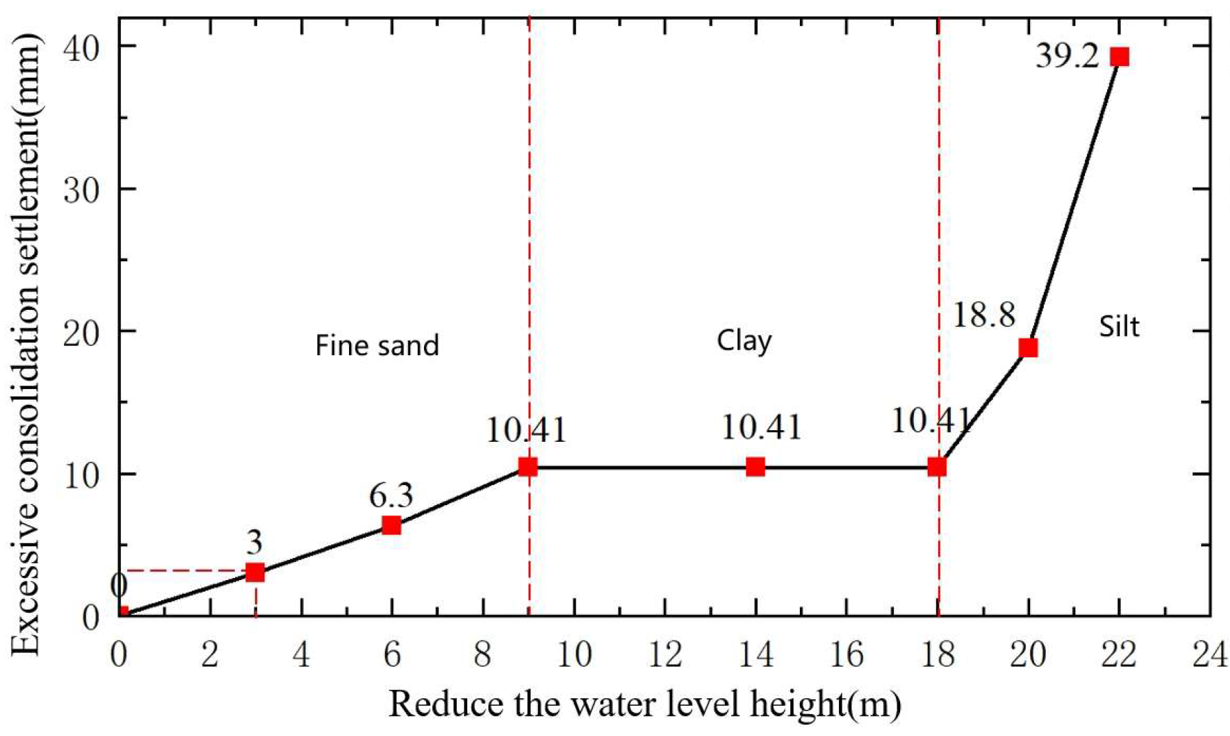
Over-consolidation settlement calculations for soil layers
Figure 16 illustrates the relationship curve between groundwater level drawdown and surface settlement derived from Equation (31). As the groundwater level decreases, the over-consolidation settlement in soil layers gradually increases, albeit at a slower rate. A 1-m drop in groundwater level causes an increase of 0.54 mm in an over-consolidation settlement. Similarly, Figure 17 and Figure 18 present the relationship curves between groundwater level drawdown and surface settlement for medium sand, coarse sand, gravelly sand, as well as silt sand, fine sand, and cohesive soil layers. The medium sand, coarse sand, and gravelly sand layers exhibit a faster rate of increase in over-consolidation settlement as the groundwater level decreases. For every 1-m decrease in groundwater level, the over-consolidation settlement of the soil increases by 2.15 mm. The fine sand and silt sand layers exhibit the fastest rate of increase in over-consolidation settlement as the groundwater level decreases. For every 1-m decrease in groundwater level, the over-consolidation settlement of the soil increases by 3.05 mm. The cohesive soil layers, however, are unaffected by groundwater level drawdown. In summary, a decrease in soil particle size leads to a reduction in the elastic modulus of the soil, while the rate of over-consolidation settlement increases as the groundwater level drops.
(2)
Groundwater control measures
Taking into account the over-consolidation settlement rate and permeability of different types of soil, develop targeted groundwater level control measures. Strictly monitor the height of groundwater level reduction during tunnel construction for gravel, crushed stone, and highly permeable strata, and if necessary, use the grouting method to control the groundwater level.
For medium sand, coarse sand, and gravel sand formations, it is necessary to strictly control the lowering of groundwater level during tunnel construction. This type of formation has a permeability greater than 10−3 and belongs to a highly permeable formation. The grouting slurry is prone to loss and the efficiency of the grouting method is low. Therefore, the effective method for controlling the groundwater level is freezing. The freezing method uses a pipe curtain to freeze and forms a closed freezing reinforcement circle with a certain thickness along the tunnel perimeter, preventing groundwater loss during tunnel construction.
Strict control is required to reduce the groundwater level during tunnel construction in silty and fine sand formations. The permeability of this type of stratum is 10−5–10−3, belonging to the medium permeability stratum. Effective methods for controlling the groundwater level include grouting and freezing. The grouting method injects grout into the soil pores in front of the tunnel face by drilling holes in the surface, reducing the permeability coefficient of the soil and minimizing groundwater loss during tunnel construction.
For cohesive soil layers, it is necessary to strictly control the decrease of groundwater level during tunnel construction. This type of stratum has a permeability of <10−5 and belongs to low-permeability strata. Effective methods for controlling groundwater levels include grouting and freezing. Among them, due to the low permeability hindering conventional grouting, the grouting method adopts high-pressure jet grouting or chemical grouting, which improves the injectability of the formation through high-pressure or chemical modification.
For the composite strata composed of the above three types of soil, the method of grouting + freezing is adopted. For high permeability strata, the freezing method is used for construction. For medium permeability and low-permeability strata, the freezing method or grouting method is selected for construction based on the site conditions.

4. Case Studies

This study explores micro-settlement control techniques through two engineering cases: the large cross-section tunnel connecting the T2 and T3 terminals beneath the Capital Airport runway, and the Yingze Street underpass project beneath the Taiyuan Railway Station.

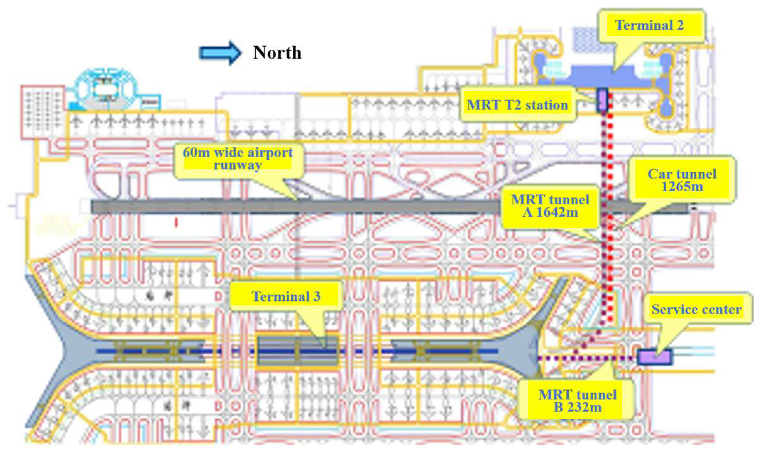
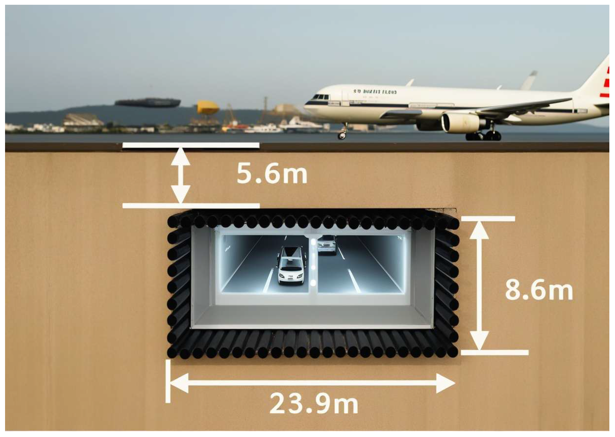
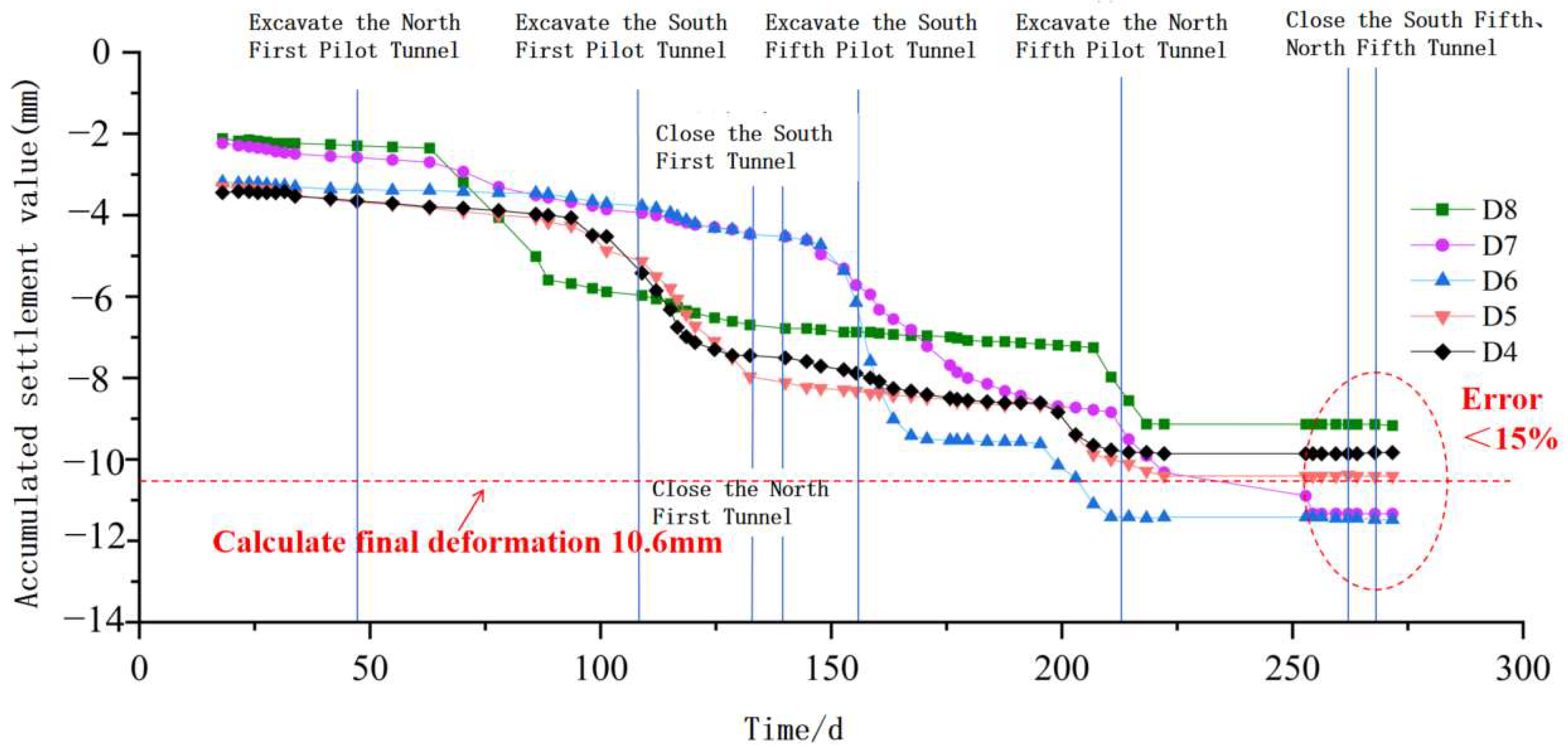
4.1. Tunnel Beneath the Capital Airport Runway

Figure 19 and Figure 20 show the plan view and cross-sectional view of the Beijing Capital Airport connector line, respectively. The cross-sectional view is shown in Figure 2. The tunnel features a single-layer, dual-span, double-arch structure. It includes a 1621-m rapid transit tunnel and a 1265-m vehicular tunnel. The tunnel crosses beneath a continuously operational runway for 232 m, with a span of 23.9 m and a depth of 5.6 m. The diameter of the pipe curtain is 970 mm, the elastic resistance coefficient of the soil is 10,000 kN/m, the elastic modulus of the concrete is 230 GPa, the elastic modulus of the pipe curtain is 200 GPa, the weight is γ = 20 kN/m3, the lateral pressure coefficient is taken as 0.5, the distance from the palm face to the initial support seal is 2 m, the wall thickness is taken as 850 mm, and the grouting pressure is 0.16 MPa.
The settlement control standards for the airport runway and taxiway are extremely stringent, requiring total settlement to remain below 30 mm and flatness deviations to be less than 1%. Controlling settlement during tunnel construction is highly challenging, as even minor errors can lead to excessive runway settlement, collapses, or catastrophic accidents, such as aircraft destruction and loss of life.
The geological formation is composed of silty clay with low stability. Since the groundwater level is below the tunnel invert, surface settlement caused by groundwater level drawdown does not need to be considered.
The pipe roof was designed as a rectangular full-ring enclosed structure. The steel pipes have a diameter of 970 mm, a wall thickness of 850 mm, and are filled with concrete. The primary support and temporary support adopt a combined steel frame and mesh-reinforced shotcrete structure. The mechanical calculation model is illustrated in Figure 21. Based on Equation (10), the total surface settlement caused by tunnel excavation is calculated as u1 = 6.8 mm.
The spacing between pipes in the pipe roof was designed to be 1000 mm. During single-pipe jacking, the grout was injected around the pipe for pressure maintenance and resistance reduction, and the grouting pressure was designed to be 0.3 MPa. An alternate pipe jacking method was employed to minimize the settlement superimposition effect. According to Equation (25), the total surface settlement caused by pipe roof construction is determined to be u2 = 3.8 mm.
The total surface settlement resulting from the tunnel construction is calculated to be u = 10.6 mm. Figure 22 presents the measured settlements of the airport runway. It can be observed that the surface settlement caused by the pipe roof construction is 4 mm, while the total surface settlement induced by the construction reaches 11.5 mm. The accuracy of pipe curtain construction, geological homogeneity, and changes in the groundwater environment can all affect surface settlement. The deviation between the measured values and predicted values at each measuring point is within 15%, and the settlement control meets the requirements for ensuring the uninterrupted operation of the Capital Airport.

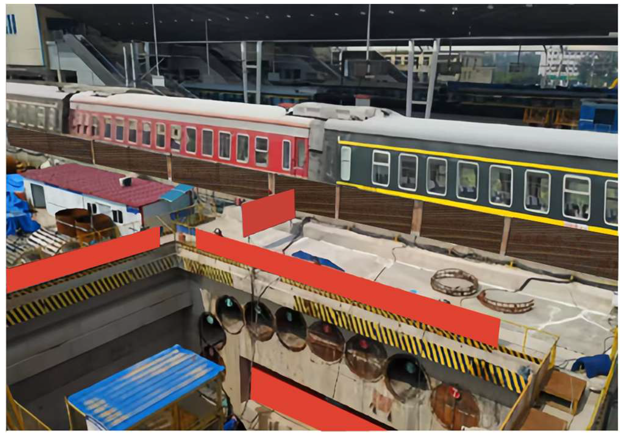
4.2. Tunnel Beneath the Taiyuan Railway Station

Figure 23 presents the Yingze Street tunnel beneath the Taiyuan Railway Station. The tunnel’s north and south lines measure 102.5 m and 105 m in length, respectively. It spans 18.2 m beneath the station, with a height of 10.5 m and a depth of 3.5 m. The maximum allowable settlement for both the railway track surface and the ground surface is 12.0 mm. An integrated support structure is employed to control settlement, as illustrated in Figure 24.
The Taiyuan Railway Station tunnel is shallowly buried at a depth of 3.5 m. It is located beneath a railway where heavy haul trains and high-speed trains frequently pass, imposing substantial dynamic loads on the structure. Millimeter-level control of surface settlement is required for this project. Therefore, a high-stiffness integrated support structure is adopted. The pipe roof is composed of steel pipes with a diameter of 2000 mm and a wall thickness of 950 mm. The mechanical calculation model is illustrated in Figure 25. The strata in the project area consist of loose to dense plain fill and soft to hard plastic new loess. Since the groundwater level lies below the tunnel invert, the surface settlement caused by groundwater level drawdown does not need to be considered.
The elastic resistance coefficient of the soil is 10,000 kN/m, the elastic modulus of the concrete is 230 GPa, the elastic modulus of the pipe curtain is 240.5 GPa, the weight is γ = 19 kN/m3, the lateral pressure coefficient is taken as 0.5, the distance from the palm face to the initial support closure ring is 2 m, the wall thickness is taken as 950 mm, and the grouting pressure is 0.16 MPa. According to Equation (10), the total surface settlement resulting from tunnel excavation is calculated as u1 = 0.79 mm.
The net spacing between steel pipes in the pipe roof was designed to be 165 mm. During single-pipe jacking, the grouting pressure around the pipe was set at 0.38 MPa to maintain pressure and reduce resistance. An alternate pipe jacking method was employed to minimize the settlement superimposition effect. Based on Equation (25), the surface settlement resulting from pipe roof construction is calculated to be u2 = 7.3 mm.
The total surface settlement induced by tunnel construction is calculated as u = 8.09 mm. Monitoring data revealed that the surface settlement caused by pipe roof construction ranged from 5.5 mm to 6.4 mm, while the total settlement resulting from the entire construction process ranged from 6.3 mm to 7.7 mm. The calculated results closely match the measured data, and the settlement control satisfies the requirements for ensuring the uninterrupted operation of Taiyuan Railway Station.

5. Conclusions

In response to settlement control requirements in complex and sensitive areas, this study takes the large-section tunnels beneath the Beijing Capital Airport runway and the Taiyuan Railway Station as the background to develop a theoretical approach and key techniques for micro-settlement control. The following conclusions are drawn:
(1)
A theoretical method for surface micro-settlement control in large-section tunnels is proposed. A calculation formula is derived to reveal the relationships between surface settlement and factors such as pipe roof stiffness, support system stiffness, pipe roof construction procedures, and groundwater level changes. Surface micro-settlement control techniques, including increasing the pipe roof stiffness, reinforcing the support system, reducing the group pipe effects, maintaining pressure and reducing resistance around the pipe, and controlling the groundwater level, are proposed.
(2)
The stiffness of the pipe roof and the overall stiffness of the support system are critical factors in controlling surface micro-settlement in large-section tunnels. This study proposes a method for determining the appropriate stiffness for the pipe roof and support system. The stiffness should be selected from the transition segment between the steep decline and the gentle slope on the stiffness-settlement curves of the pipe roof and the support system. If the stiffness of the pipe roof combined with the primary and temporary supports fails to meet the requirements for micro-settlement control, an integrated support system with higher stiffness can be adopted.
(3)
The primary causes of surface settlement during pipe roof construction are voids between the pipes and the surrounding soil, as well as the settlement superimposition effect of group pipe construction. This study proposes a pressure-maintaining and resistance-reducing technique around the pipe by appropriately regulating grouting pressure to minimize surface settlement during single-pipe jacking. It is recommended that the spacing between simultaneously installed jacked pipes be greater than half the width of the settlement trough (λi) to mitigate the settlement superimposition effect.
Tunnel construction causes groundwater loss, resulting in a drop in the groundwater level, which subsequently leads to over-consolidation settlement in the soil. For over-consolidation-sensitive strata, such as medium sand and coarse sand, water-blocking methods like freezing, grouting, or a combination of both are required. In cases where a circumferentially enclosed pipe roof is used, the internal pipe freezing method is prioritized for its superior effectiveness. For over-consolidation-insensitive strata, such as gravel and cobble with high permeability, water-blocking treatments are not required.

Author Contributions

Conceptualization, Z.T. and Z.Z.; methodology, Z.T.; investigation, Z.D.; resources, Z.L.; writing—original draft preparation, Z.T., and Z.D.; writing—review and editing, Z.Z. and Z.L. All authors have read and agreed to the published version of the manuscript.

Funding

This research was funded by the National Key R&D Program of China (2023YFC3806701).

Data Availability Statement

The data that support the findings of this study are available upon request from the corresponding author, [Zhengquan Ding], upon reasonable request.

Conflicts of Interest

Authors Zhengquan Ding and Zhanxian Li were employed by the company China Railway Construction Co., Ltd. The remaining authors declare that the research was conducted in the absence of any commercial or financial relationships that could be construed as a potential conflict of interest.

References

  1. Chen, J. Effects of reinforcement on behaviors of shallow tunnel and settlement of ground surface. J. Guizhou Univ. (Nat. Sci.) 2015, 32, 126–130. [Google Scholar]
  2. Dai, Y.; Ai, G.; Huang, D.; Chen, G.; Zhou, C. Research on the optimization of support structure and construction method of metro station in muddy siltstone. Mod. Tunn. Technol. 2020, 57, 996–1001. [Google Scholar]
  3. Guo, J.; Yu, S.; Ding, H. Optimized analysis of support parameters of 3-lane highway tunnels. Technol. Highw. Transp. 2013, 6, 76–80+84. [Google Scholar]
  4. Zhan, H. Research on ground deformation caused by pipe jacking construction. Chin. J. Undergr. Space Eng. 2008, 4, 583–585. [Google Scholar]
  5. Peck, R.B. Deep excavations and tunneling in soft ground. In Proceedings of the 7th International Conference on Soil Mechanics and Foundation Engineering, Mexico City, Mexico, 25–29 August 1969; pp. 225–290. [Google Scholar]
  6. Gong, S.; Yang, Y.; Chen, S. Analyses on ground surface settlement due to extra-shallow-underground-pipe jacking with curve by stochastic medium theory. J. Chongqing Jiaotong Univ. (Nat. Sci.) 2005, 24, 95–98+103. [Google Scholar]
  7. Sun, M.; Xu, W. 3D numerical simulation of pipe-curtain method in soft soils. Chin. J. Geotech. Eng. 2006, 28, 1497–1500. [Google Scholar]
  8. Ji, X.; Long, B.; Yang, X. 3D simulation analysis of closely jacking pipe in pipe curtaining pre-reinforcement. Chin. J. Undergr. Space Eng. 2016, 28, 267–274. [Google Scholar]
  9. Yang, X.; Zhang, K.; Li, Z.; Deng, M.; Xiao, Z. Influence of steel pipe jacking on earth surface settlement in pipe roof pre-construction method. J. Shenyang Univ. Technol. 2012, 34, 469–473. [Google Scholar]
  10. Yang, Q.; Zhao, B. Experimental and theoretical study on the surface subsidence by dewatering of foundation pit in phreatic aquifer. Chin. J. Rock Mech. Eng. 2018, 37, 1506–1519. [Google Scholar]
  11. Wu, Y. Research on the deformation due to dewatering and excavation of deep foundation pit of subway station in phreatic aquifer. Lanzhou Univ. Technol. 2016. [Google Scholar]
  12. Wen, S. Estimation method for ground settlements of the karst tunnel in soil surrounding rock. Mod. Tunn. Technol. 2018, 55, 73–79. [Google Scholar]
  13. Gu, S.; Li, Z.; Li, Y. Analyses on ground settlement induced by pre-precipitation in deep foundation pit project. Sci. Technol. Eng. 2018, 18, 233–237. [Google Scholar]
  14. Tan, Z.; Ma, D.; Sun, X.; Chen, Y.; Wang, W. Construction technology of large span tunnel under the non-stop flight runway. China Civ. Eng. J. 2015, 48, 378–382. [Google Scholar]
  15. Liu, Y.; Shi, P.; Pan, J.; Yu, C. Analysis of transverse ground settlement and pipe interaction of super-large pipe roofing in Gongbei Tunnel. Tunn. Constr. 2018, 38, 1680–1687. [Google Scholar]
  16. Wang, X. Study on Key Techniques for Settlement Control in the Construction of Yingze Street Beneath Taiyuan Station. Master’s Thesis, Taiyuan University of Technology, Taiyuan, China, 2021. [Google Scholar]
  17. Tan, Z.; Sun, X.; Ma, D.; Ma, Y. Experimental research of pipe-roof pre-supporting technology for the shallow large-span tunnel. China Civ. Eng. J. 2015, 48, 429–434. [Google Scholar]
  18. Aghajari, M.; Dehghan, A.N.; Lajevardi, S.H. Optimizing Se-quential Excavation Method for Ground Settlement Control in Tehran Subway Tunnel Line 6. Geotech. Geol. Eng. 2024, 42, 3595–3614. [Google Scholar] [CrossRef]
  19. Morovatdar, A.; Palassi, M.; Ashtiani, R.S. Effect of pipe characteristics in umbrella arch method on controlling tunneling-induced settlements in soft grounds. J. Rock Mech. Geotech. Eng. 2020, 12, 984–1000. [Google Scholar] [CrossRef]
  20. Chakeri, H.; Ozcelik, Y.; Unver, B. Effects of important factors on surface settlement prediction for metro tunnel excavated by EPB. Tunn. Undergr. Space Technol. 2013, 36, 14–23. [Google Scholar] [CrossRef]
  21. Mousapour, H.; Chakeri, H.; Darbor, M.; Hekmatnejad, A. Evaluating the wear of cutting tools using a tunnel boring machine laboratory simu-lator. Min. Miner. Depos. 2023, 17, 28–34. [Google Scholar] [CrossRef]
  22. Chakeri, H.; Darbor, M.; Shakeri, H.; Mousapour, H.; Mohajeri, V. Experimental and numerical investigation of the TBM disc cutter wear using a new tunnel boring machine laboratory simulator. Heliyon 2024, 10, e37148. [Google Scholar] [CrossRef] [PubMed]
Figure 1. Mechanical calculation model of tunnel cross-section.
Applsci 15 04375 g001
Figure 2. Load calculation model of pipe-roof.
Applsci 15 04375 g002
Figure 3. Mechanical calculation model for a single pipe.
Applsci 15 04375 g003
Figure 4. Over-consolidation settlement calculation model.
Applsci 15 04375 g004
Figure 5. Relationship curve between load-to-pipe roof stiffness ratio and surface settlement.
Applsci 15 04375 g005
Figure 6. Relationship curve between pipe roof stiffness and surface settlement.
Applsci 15 04375 g006
Figure 7. Schematic diagram of primary support combined with temporary support.
Applsci 15 04375 g007
Figure 8. Relationship curve between load-to-support system stiffness ratio and surface settlement.
Applsci 15 04375 g008
Figure 9. Relationship curve between support system stiffness and surface settlement.
Applsci 15 04375 g009
Figure 10. Superimposition coefficient for alternate construction of the pipe roof.
Applsci 15 04375 g010
Figure 11. Schematic diagram of the pipe roof construction sequence.
Applsci 15 04375 g011
Figure 12. Relationship between grouting pressure and surface settlement.
Applsci 15 04375 g012
Figure 13. Relationship between pipe roof spacing and surface settlement under different grouting pressures.
Applsci 15 04375 g013
Figure 14. External wall pressure maintenance and resistance reduction system.
Applsci 15 04375 g014
Figure 15. Installation diagram of components for compartmentalized-partition-ring-based grouting pressure maintenance and resistance reduction technique in ultra-long pipe jacking.
Applsci 15 04375 g015
Figure 16. Over-consolidation settlement in highly permeable soils.
Applsci 15 04375 g016
Figure 17. Consolidation settlement in medium, coarse, and gravelly sand layers.
Applsci 15 04375 g017
Figure 18. Over-consolidation settlement in semi-mixed soil layers.
Applsci 15 04375 g018
Figure 19. Plan view of the large cross-section tunnel beneath the Capital Airport runway.
Applsci 15 04375 g019
Figure 20. Cross-section of the large cross-section tunnel beneath the Capital Airport runway.
Applsci 15 04375 g020
Figure 21. Cross-section of the tunnel.
Applsci 15 04375 g021
Figure 22. Time history diagram of surface deformation.
Applsci 15 04375 g022
Figure 23. Large cross-section tunnel beneath the Taiyuan Railway Station.
Applsci 15 04375 g023
Figure 24. Cross-section of the tunnel beneath the Taiyuan Railway Station. (Unit: mm).
Applsci 15 04375 g024
Figure 25. Cross-section of the Taiyuan Railway Station tunnel.
Applsci 15 04375 g025
Disclaimer/Publisher’s Note: The statements, opinions and data contained in all publications are solely those of the individual author(s) and contributor(s) and not of MDPI and/or the editor(s). MDPI and/or the editor(s) disclaim responsibility for any injury to people or property resulting from any ideas, methods, instructions or products referred to in the content.

