1. Introduction
In reconstructive surgery of extensive mandibular defects, implants predominantly made of titanium are used, which are custom-designed thanks to the widespread adoption of CAD/CAM technology. Implant design aims to achieve stiffness comparable to bone by reducing the stiffness of metal implants, whose material has an elastic modulus several times greater than that of bone tissue. Cortical bone exhibits an elastic modulus between 8 and 20 GPa, whereas titanium has an elastic modulus of 100–120 GPa. An excessively rigid implant leads to bone overload in the bone screw regions and simultaneous underloading in areas where the implant, rather than the bone, transfers the load. This results in bone resorption from both causes. Reducing implant stiffness improves load distribution to the bone, which can be achieved by adjusting the wall thickness or decreasing the elastic modulus. Additive manufacturing technologies allow the use of metals or polymers with low elastic modulus and enable the production of thin walls, shortening the extent of osseointegration with the bone for lattice structures and cellular materials. These solutions are currently very popular and clinically applied due to their expected beneficial effects on load distribution. The most severe clinical failure is mandibular prosthesis fracture; therefore, the design and manufacturing of bone implants require strength analysis to ensure that reducing stiffness does not compromise the required load-bearing capacity. The most effective method for assessing implant load-bearing capacity is numerical simulation [
1,
2].
However, the accuracy of the analysis depends on boundary conditions, including loading and support conditions of the model, as well as material properties. In the case of the mandible, it is crucial to replicate occlusal loading conditions in the model, especially the oblique forces associated with mastication.
Current mandibular implant design lacks the application of previous research findings that highlight the significance of asymmetric occlusal load transfer in the mandible. Van Loon et al. [
3] demonstrated that occlusal loads are transferred asymmetrically, with the balancing-side joint being significantly more loaded. It was noted that if the greatest bite force occurs on the left side, the contralateral joint on the right side bears the highest load. A clinical study confirmed a greater reduction in temporomandibular joint (TMJ) space on the balancing condyle compared to the working condyle during mastication, with intra-articular distances significantly increasing for bolus thicknesses between 5 and 15 mm. The study showed that despite the absence of support in one joint due to fracture and loss of the mandibular head, bite forces within the normal range can still be generated. However, previous simulation studies have employed an overly simplified occlusal force model, considering only forces perpendicular to the occlusal plane. The current mandibular implant design lacks the application of findings that underscore the importance of asymmetric occlusal load transfer [
4,
5].
The objective of this study was to evaluate, using the Finite Element Method (FEM), the load-bearing capacity of a mandibular prosthesis under unilateral joint support contralateral to the occlusal side while generating a lateral oblique masticatory force. The hypothesis of this study was that the load-bearing capacity of extensive mandibular prostheses is significantly underestimated when assuming mandibular support in the joint on the occlusal side, compared to the assumption of a perfect osseointegration between the implant and the bone. FEM simulations of occlusal load transfer considered two TMJ’s support scenarios: one with both joints supported and another with only the joint opposite to the bite side supported. Additionally, the influence of bone ingrowth or its absence at the implant interface was examined.
2. Materials and Methods
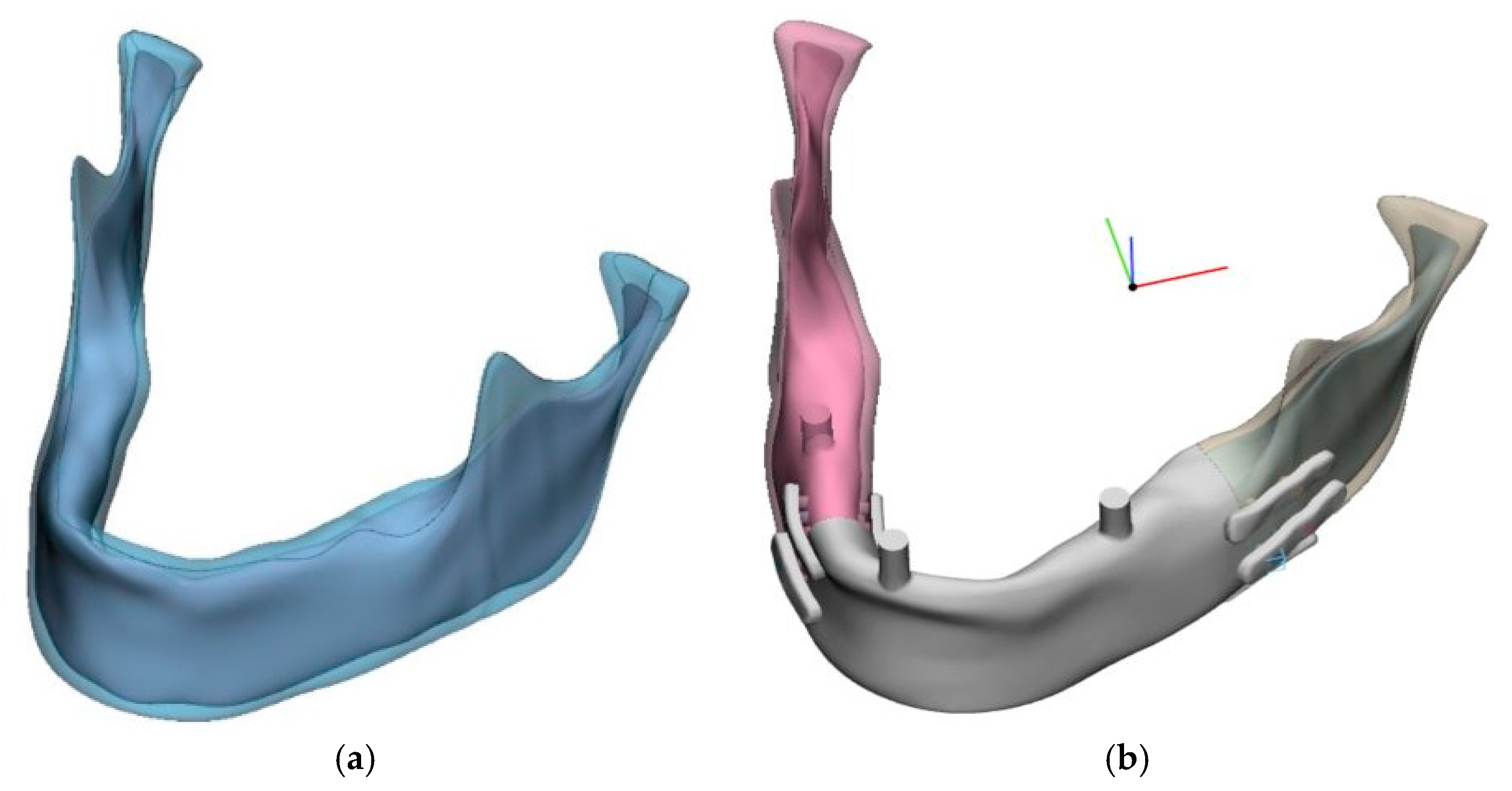
Numerical models were prepared using CAD tools (SolidWorks) to accommodate individual anatomical characteristics of the mandible. A spatial model of a computationally reconstructed mandible with average anatomical features was selected, from which a parametric model was derived (
Figure 1).
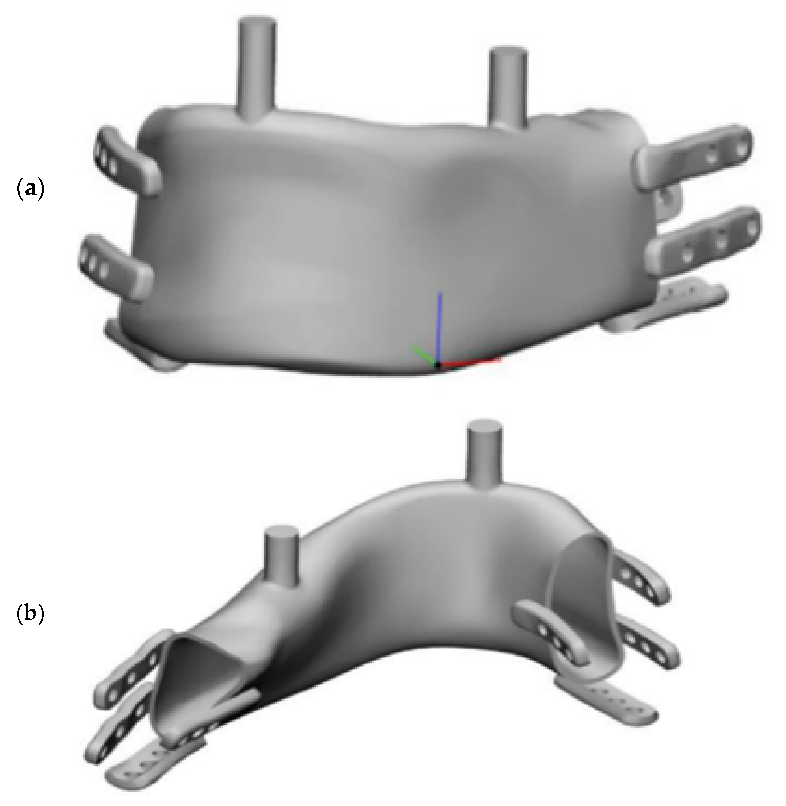
The mandibular model included a cortical bone plate, while trabecular bone behavior was approximated using a homogeneous internal structure. The model was constructed based on a reconstruction from a surface triangular mesh (STL) using B-spline curves, as automatic surface reconstruction methods failed despite mesh repair and achieving a continuous, defect-free STL mesh. No software was available to directly generate a finite element mesh from the STL. However, this approach offered the advantage of allowing control over the bone thickness dimensions in the region of the implant fixation screw. A resection area was designated, and a prosthetic model was designed (
Figure 2), shown in assembly view with the mandible.
Fixation screws of 2 mm in diameter and 6 mm in length were assumed, simplified to cylindrical shapes without threads. Cylinders were introduced for the molars and incisors to allow proper occlusal support alignment with the bone surface, maintaining the occlusal plane distance. The resection area, implant model, and bone fixation region were designed in consultation with an oral and maxillofacial surgery specialist. Fixations were designed similarly to standard bone fixation plates to facilitate intraoperative manual adaptation by surgeons.
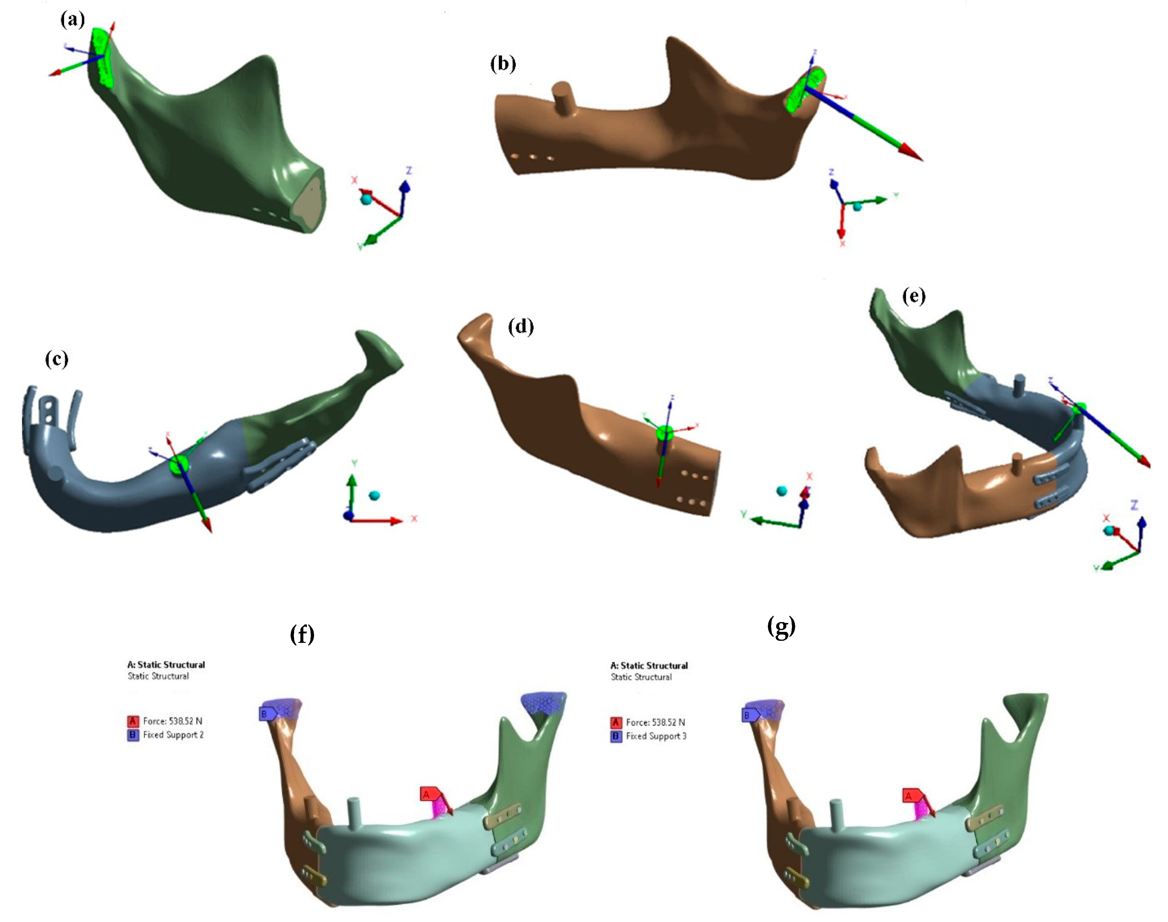
Figure 3 presents the mandibular model with an implant, indicating joint support points and three occlusal support variants on the incisor (C), natural molar (D), and prosthetic molar on the mandibular prosthesis side (E). Muscle attachment areas and force vectors are also shown.
Muscle force vectors and magnitudes (active forces) were activated in the model according to one of the three analyzed bite scenarios (support reaction enabled in simulation). Muscle force values were based on known physiological data and previous FEM studies to ensure identical oblique occlusal reaction forces across cases, reaching the maximum recorded human values [
6,
7].
Pilot studies (
Figure 4) determined joint and occlusal reaction forces under bite conditions on the left or right molar or incisor. Results indicated that unilateral lateral occlusal force (E) on the prosthesis side (left) rather than the natural mandible side (right) was critical. This load condition was adopted for further strength analysis.
Figure 5 shows that joint reaction directions matched the physiological condylar pressure orientation within the articular fossa, while lateral oblique occlusal forces were identical regardless of whether joint support was included on the bite side or limited to the contralateral joint. Further comparative studies consistently applied an oblique force of 538 N generated by muscle activation.
To enhance FEM accuracy, local mesh refinement was introduced in high-stress regions. A minimum of two elements per section thickness is required for reliable FEM analysis; in this case, at least three finite elements per implant wall thickness and five per bone fixation plate thickness were achieved, ensuring an adequately refined mesh for precise results and accurate stress-strain calculations. The element statistics option in ANSYS was used to provide detailed information on the types of elements applied (
Figure 5). The final implant mesh contained 531,644 nodes and 338,239 tetrahedral elements. A non-coherent mesh interface was used between the implant wall and bone fixation plates due to their complex geometry.
Attempts to create a node-to-node connection failed due to the intricate implant and plate shapes. Non-coherent connections allow load transfer, though local finite element artifacts at interface boundaries should be disregarded, similar to sharp edges or nodes on material interfaces [
8].
FEM simulations were conducted in ANSYS within the linear elasticity range on an available computer with average computational power, equipped with a 3.0 GHz processor and 32 GB RAM. The calculations were divided into two threads to enhance performance. The linear behavior was applied to both materials and contact conditions, which were considered either as non-existent or as a bonded condition between the implant and the bone. The evaluation criterion was the stress in the titanium implant during the transmission of the same bite force in terms of direction and magnitude, caused by muscle activities tested in the pilot study. In the assessment, the criterion of equivalent stress according to the maximum distortional strain energy density (based on Huber-Mises-Hencky’s theory) was applied. Principal maximum and minimum stresses were also presented to better understand whether, in critical areas, the equivalent stress arises from a single dominant stress component or from the difference between tensile and compressive stresses. The following material parameters were adopted for the mandible:
Numerical studies were conducted for four variants of load transfer and implant fixation with the mandibular stumps:
The first variant assumed osseointegration at the interface between the implant and the bone stump for a model supported in both joints (
Figure 4g);
The second variant assumed osseointegration at the interface between the implant and the bone stump for a model supported in one joint on the side opposite to the occlusal load (
Figure 4f);
The third variant assumed no osseointegration and connection exclusively through anchoring screws for a model supported in both joints (
Figure 4g);
The fourth variant assumed no osseointegration and connection exclusively through anchoring screws for a model supported on one side in the joint opposite to the occlusal load (
Figure 4f).
The study of ideal osseointegration aimed to determine whether the assumption of bilateral joint support or optimistic osseointegration has a greater impact on the results.
3. Results
The objective of numerical simulations was to model the stress state occurring in the implant and mandible model during the transfer of critical occlusal loads.
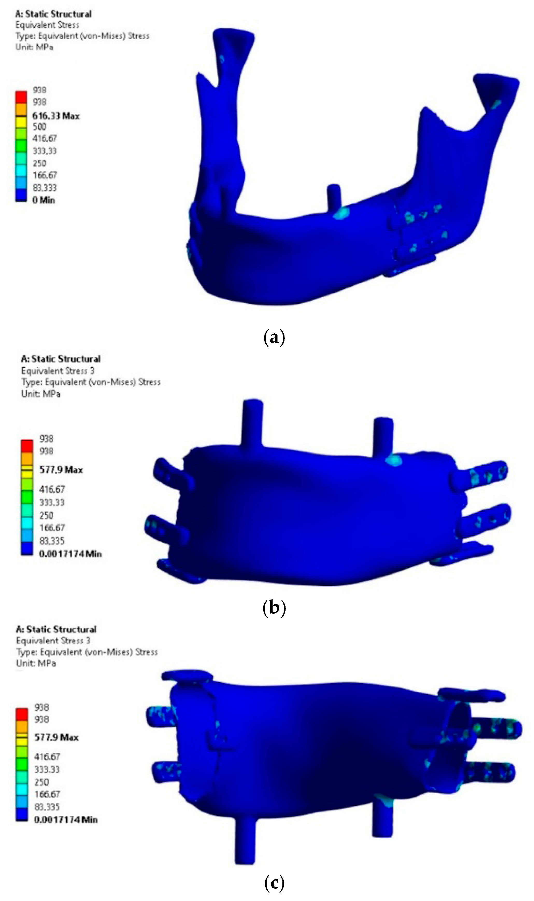
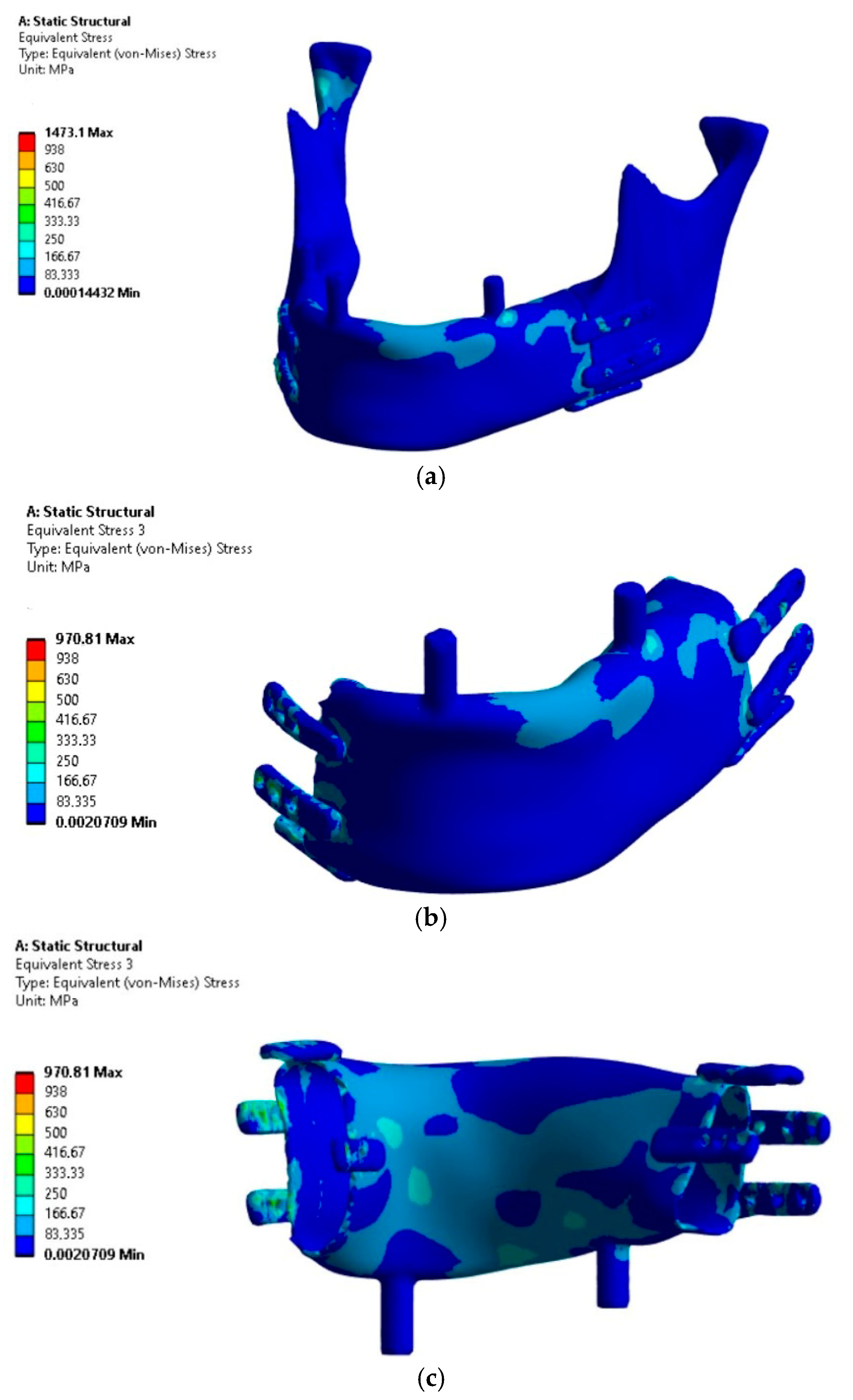
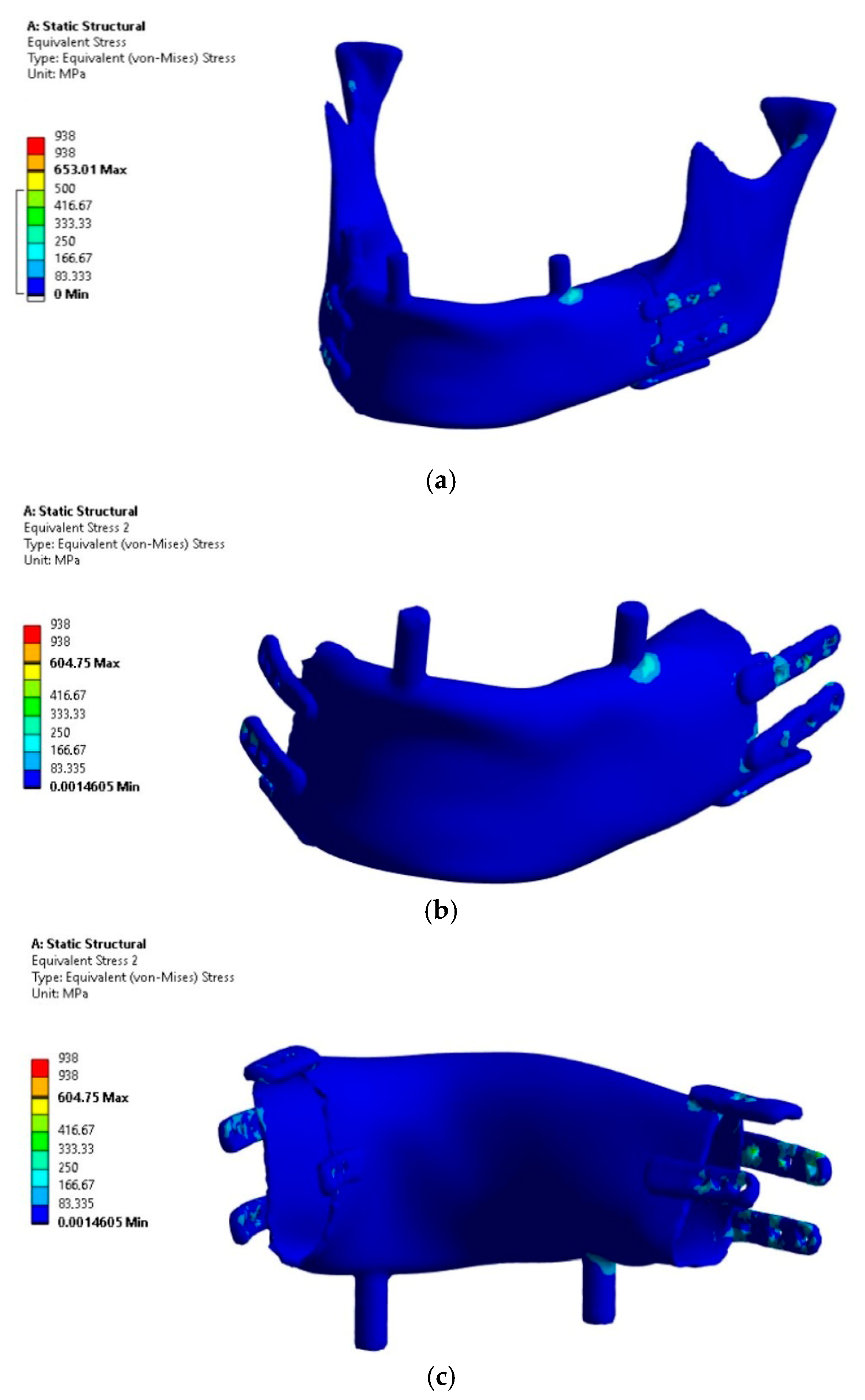
The analysis focused on the implant’s load-bearing capacity depending on the support conditions, while the stress results in bone tissue should be considered indicative due to the lack of mesh densification and reinforcement near the fixation plates. The results of the load-bearing capacity verification of the mandibular implant subjected to four load variants are presented in
Figure 6,
Figure 7,
Figure 8 and
Figure 9. The presentation includes Huber-Mises (H-M) equivalent stresses. A threshold value of 938 MPa was introduced in the stress scale, representing the strength of pure titanium [
11].
The analysis of the results allows concluding that Variant IV, as expected, proved to be critical due to the assumed conditions of lack of joint support on the side of the occlusal load and the absence of implant osseointegration with the bone stumps.
The highest H-M stress values, excluding artifacts (edges and incoherent finite elements at the mesh connection boundaries in fixations), did not exceed 250 MPa.
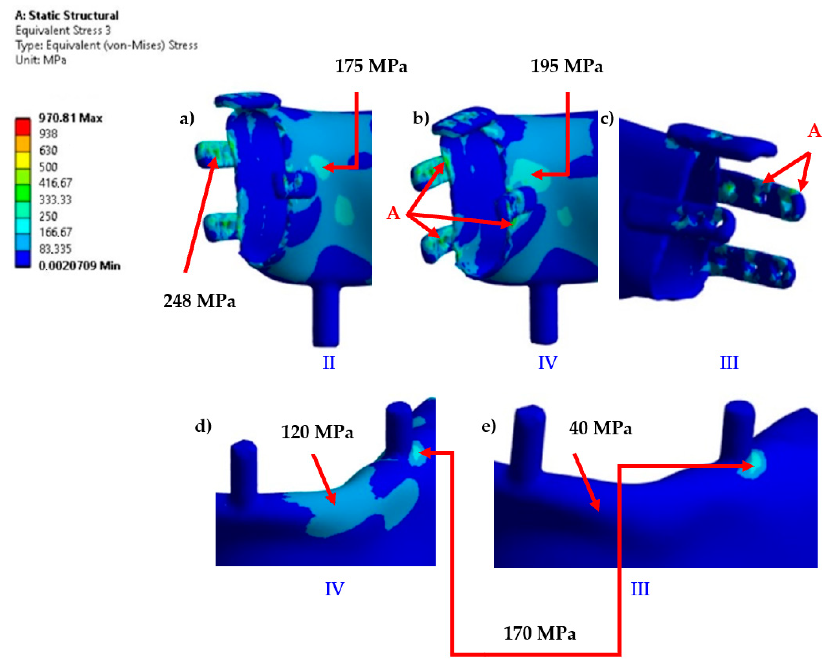
The most stressed areas were the fixation plates; however, in variants I and III, they were located on the bite side joint (left), while in variants II and IV, they were on the side closer to the contralateral joint. For better comparison of variants, the values of artifacts “A” in singular nodes, located on sharp edges and material or mesh inconsistencies, were indicated, though these were not considered as evaluation criteria. Obtaining an exact stress solution in such areas increases the analysis cost beyond the average available computational power and is therefore not applied, although it is feasible for smaller models [
6]. If the mesh in this area is not sufficiently refined to provide a physically accurate stress gradient, in such cases, it is necessary to exclude finite elements containing nodes with artifacts and, based on experience, evaluate the result in the next element not associated with the artifact. Evaluation outside the finite elements affected by artifacts showed that the stress values in the plates were similar to those in the body of the implant. However, in these areas, stress values should not be treated as precise criteria but should be based on the comparative observation of stress trend changes between loading cases. The values in the body of the implant are clearly distinct, as it was significantly more loaded compared to variants I and III. Similar stress values in the body occurred only locally due to bending around the occlusal tooth support or from artifacts at the edges of the fixation plate, whereas in variants II and IV, the highest values were found in areas where, for variants I and III, the stresses did not exceed the lowest threshold of the scale (
Figure 10).
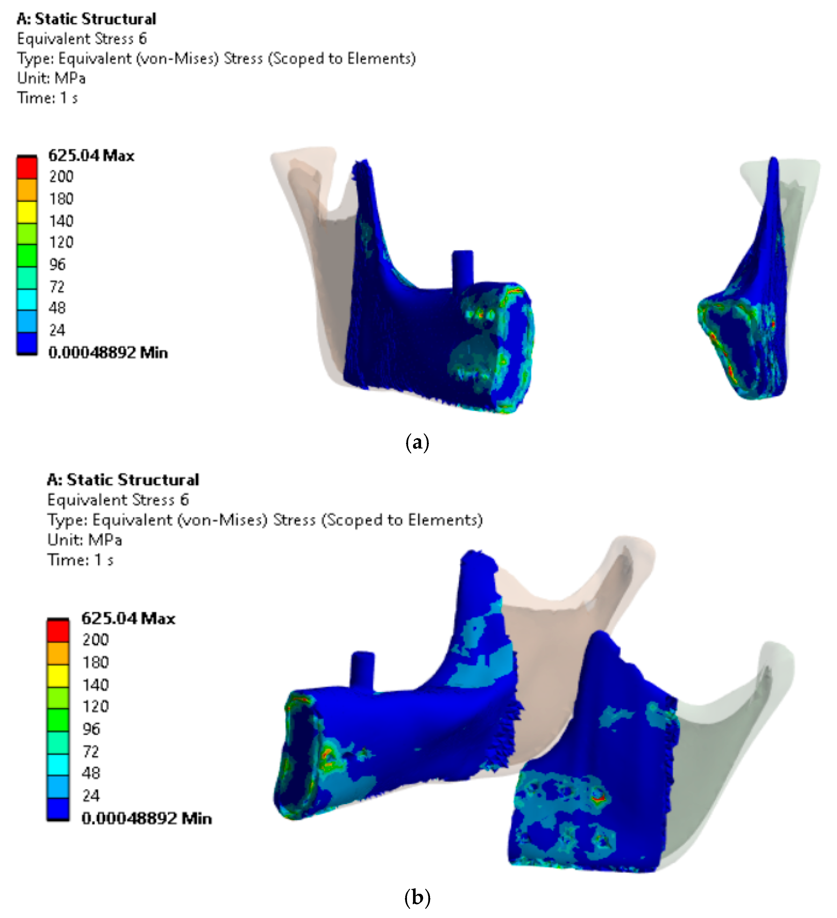
The analysis of H-M reduced stresses in the bone tissue within the implant fixation area for Variant IV (
Figure 11), where three screws per fixation plate were used, indicated that stresses in the bone locally reached up to 140 MPa (excluding localized stress concentrations in artifacts).
The principal stress analysis in the implant revealed a complex stress state. Areas of high stress concentration were identified, where the implant was subjected to both compression and tension. The maximum principal stresses exceeded 500 MPa in regions where H-M stresses did not exceed 250 MPa. The minimum principal stresses reached -250 MPa in the same area. The H-M stresses did not reach such high values compared to the maximum principal stresses due to relatively smaller stress differences along the principal directions in this area. The principal stress direction analysis indicated that the main tensile and compressive stresses were oriented obliquely to the occlusal plane (
Figure 12).
4. Discussion
In simulation studies, the exclusion of the load-bearing capacity of the temporomandibular joint on the occlusal side resulted in a change in force distribution between the supports and an increase in mandibular bending. The mandible, when biting on the tooth cusp, has a hinged support point at this location and is bent by the active muscle forces relative to the supports. The bending of the mandible is fundamentally influenced by the type of symmetrical support in both joints or asymmetrical support, where on the occlusal side, the support is weaker (less rigid). “Weaker support” is a colloquial term that, in the context of mechanics, explains the fact that the support reaction depends on its compliance. Rigid supports bear more load compared to compliant ones. On the occlusal side, the condyle moves downward due to the thickness of the food being chewed, as explained by anatomy and kinematics. During the closing phase of chewing, the decrease in joint space is more pronounced on the balanced side than on the bite side. Joint space evaluation requires a statistical approach and additional research methods, along with indirect calculation of the condyle-fossa distance [
4,
12,
13,
14,
15,
16,
17,
18,
19,
20,
21,
22,
23].
In the stomatognathic system, the soft articular disc participates in load transfer within the joint. As the condyle moves downward from the glenoid fossa, the disc changes its position and shape, which affects its stiffness. This is a complex system that is difficult to model accurately in its entirety along with the mandible. The reason for this complexity lies in the large displacements, which result not only from the movement of the mandible and sliding contacts but also from the deformation of the discs, which is a result of large strain [
24,
25,
26]. In FEM, this presents a significant challenge in achieving convergence of the numerical solution. Although successful attempts have been made to simulate the loading of the articular discs during mandibular movements [
26], the activation of muscle forces remains within the realm of arbitrary decisions. This is the greatest challenge in modeling bite load transfer in the mandible, which arises from the issue of its static indeterminacy. In mechanics, such a system can be balanced by any muscle activity, provided it satisfies the single condition imposed by physiology, that muscles act in their physiological direction. It remains unclear whether the nervous system controls the muscles with the aim of optimizing maximum bite force while minimizing muscular effort or minimizing joint loading [
27]. It should be noted that there is an additional unknown related to the difficulty of determining whether the optimal minimal load distribution on the joints should be symmetric or asymmetric. This arises from the fact that during unilateral biting, the condyle’s displacement causes a disc configuration that is not predisposed to carry such a large load compared to the disc on the opposite side, where the condyle remains deeper within the joint. It is unclear whether the disc configuration can modulate the response in a simple mechanical way through reduced compliance or if the nervous system and muscle activity modulation are involved in this process [
27], especially due to the connections of the superior belly of the lateral pterygoid with the articular disc.
Leaving aside these unknowns, which are still difficult to definitively resolve, we would like to demonstrate that assuming symmetrical alignment of stiffness in both joints is risky in implant design, especially considering clinical studies [
4,
12,
28]. Clinical studies suggest that, in such cases, the support in the joint on the occlusal side seems to not align with the assumption of rigid support in the model, which, in response to compression, generates large reaction values and alters the bending configuration in the mandible model. As stress comparison demonstrated, support in both joints led to a significant underestimation of stresses. Greater joint loading on the contralateral side to the clenching side is indicated in several studies [
6,
14,
24]. In the studies conducted by [
29] during unilateral posterior clenching on block, the contralateral condyle was displaced cranially and ventrally. Investigation on monkeys also reported [
30] that bone strain underneath the temporomandibular ligament on the balancing side is larger. In the studies conducted by [
24] during forceful static biting, the condyle–fossa distance decreases more on the contralateral (balancing) side than on the working side, and this decrease in distance is related to the degree of clenching force. Although the authors note that the method does not allow for direct interpretation of the result as increased compression of the disc, in the absence of newer, more accurate techniques for understanding this phenomenon in the human mandible, it is prudent to maintain this cautious assumption in implant design. In our team, we encountered a case of regained high clenching efficiency following the complete loss of one condyle [
5], when a fracture was not diagnosed on the X-ray image due to a medical error, after which displacement and resorption of the fractured condyle occurred below the attachment of the lateral pterygoid. This intriguing case demonstrated that, without support in one of the joints, the muscular system can achieve balance on two supports and still generate a reaction force on the occlusal support comparable to that of a healthy mandible. In the work by Loon [
3], an assessment of asymmetric joint support conditions was conducted under the assumption of a simplified vertical occlusal force application. In our study, no simplification to a vertical force was applied; instead, an oblique force was used, which, along with asymmetric joint support, critically influences load transfer and implant load-bearing capacity. The method of load application and support differed significantly from previous studies, making direct result comparisons difficult. Vertical bite force is a specific case of loading, whereas the supports in the mandible on the articular joint surfaces and tooth cusps are naturally oriented at significant anatomical angles. Additionally, the distribution of forces may be influenced by the shape and properties of the food. Therefore, there is a general consensus in the literature that oblique forces should be assumed in the range of 20–45°. Muscles generate horizontal components on the cusps while simultaneously inducing bending of the mandible in the horizontal plane and torsion in the joints. In Loon [
3], lateral pterygoid muscle detachment is observed on the side of the TMJ prosthesis. We aimed to analyze a case where all muscles generate forces and thus arbitrarily assumed that the attachments were preserved.
The stress values obtained for the mandibular bone model in Variant IV were consistent with those reported in the study by Chia-Hsuan et al. [
15], where both FEM analysis and experimental validation were carried out. In their study, FEM simulations were performed under an occlusal load of 600 N, applied directly as an active force, with 200 N distributed on the molars and 100 N on the premolars. A shift from a vertical to an oblique occlusal force direction resulted in an increase in stress from 778 MPa to 925 MPa. Following topological optimization of the implant design, stress was reduced from 925 MPa to between 720 and 764 MPa.
In contrast, our study did not include topological optimization, and the stress values did not exceed the tensile strength of pure titanium, except in areas with artifacts caused by material and geometric notches. In the study by Chia-Hsuan et al. [
15], the bone screws used had a diameter of 2.4 mm, and a 1.6 mm thick fixation plate was applied. The implant in their study, similar to our numerical model, demonstrated adequate load-bearing capacity, with the fixation plates being the critical stress area. However, in the experimental study [
15], vertical occlusal loads were applied, and failure occurred in the lower fixation screws at a load range of 1678–2163 N. This experiment showed that the system’s load-bearing capacity was considerably higher than the numerical predictions made in study [
15]. The experiment applied occlusal forces to rigidly supported, significantly shortened mandibular stumps, altering bending conditions by changing the bone length and the lever arm of the occlusal force relative to joint support. Both the FEM model and the experiment in [
15] involved fixation at both temporomandibular joints, which differs significantly from real-world conditions. Despite this, the stress analysis results indicated that bone failure would occur before implant failure. Furthermore, the experimental validation in study [
15] confirmed that failure tends to occur in the bone screw regions.
In our study, bone tissue stresses also approached the critical threshold of 140 MPa but did not exceed the cortical bone strength of the mandible [
13]. However, it can be assumed that patients do not fully regain muscular function, and occlusal forces sufficient for food mastication range between 250 and 300 N. In clinical practice, overload-induced bone resorption occurs around bone screws, which aligns with stress values when occlusal forces in the model are reduced by half. However, the problem addressed in this study was the risk assessment of implant fracture, which occurs in clinical practice [
10,
14,
15,
16,
17,
18]. An example is the study by Huo et al. [
15], where 40 out of 187 implanted lattice implants experienced clinical fractures. The stress in the designed implant in one of the lattice bars was below 80 MPa, significantly lower than the permissible values for titanium obtained via the selective laser melting (SLM) method. The authors attempted to justify fractures by stress concentration in a single finite element, which, however, suggests an FEM artifact due to finite element mesh. The failure was explained by the lower actual cross-sectional strength compared to the model due to the presence of pores inherent to the SLM technology. Our results indicate that in preclinical numerical verification of mandibular implant load capacity, occlusal forces cannot act solely in a vertical direction, and temporomandibular joint support should not be symmetrical [
14,
16,
17,
19]. Our objective is not to engage in extensive discussions with every study in this domain, as their number is vast, but rather to highlight the implications from studies [
3,
12].
In summary, it should be emphasized that in simulation models for the study of mandibular prosthesis load-bearing capacity, the most important criteria are the method of model support and muscle activity. In our research, the assumption of perfect fusion had a secondary impact on the result. There is general agreement that the decisive factor in load-bearing studies is the maximum muscular effort that generates the maximum bite force. However, our studies, in comparison with others, indicate that this is not the only criterion. According to the fundamentals of mechanics, it is known that internal forces (bending moments, torsion, and shear) depend on the compliance of the supports. Various approaches to mandibular support during the load-bearing capacity studies of mandibular prostheses can be distinguished. The first approach involves neglecting the active forces of the muscles, and instead of generating reactions in the joint, the condylar head is directly loaded with an active force until the implant fractures, with the mandible rigidly fixed in an arbitrarily chosen cross-section. This approach is suitable for comparing load-bearing capacities between solutions but overestimates the load because the mandible is not a cantilever support rigidly fixed on one side. The second approach involves obtaining bending through active forces on the mandibular frame supported on the tooth and in the joints. Disabling the support in the joint on the occlusal side increases the bending of the mandible. This is due to the condyle bending in the joint without support, causing the muscle forces on that side to generate a greater moment relative to the support on the tooth, which, as the only support on that side, is forced to take on the load.
The presented methodology for numerical preclinical verification of mandibular implant load capacity, while enabling safer implant design, has limitations arising from model simplifications. The model does not replicate the actual condyle mobility in the joint on the occlusal side upon mandibular opening and condyle movement depending on food thickness. We encountered significant computational costs with models incorporating contact with joint sliding and have not yet achieved convergence in nonlinear analysis. We present our study at this stage to highlight the risk of underestimating implant load capacity in commonly adopted computational schemes with symmetrical joint support. We arbitrarily assumed muscle efficiency to generate comparable occlusal forces, allowing for relative comparisons and evaluations of tested solutions [
6]. Modeling methods for muscle forces based on optimizing minimal muscle effort or joint reactions and their implementation in strength analysis are also a future development pathway.


