1. Introduction
Solar energy generation has recently emerged as one of the most promising renewable resources [
1]. The electric power grid is increasingly affected by the safe and reliable operation of rapidly growing solar energy production [
2]. During a grid fault, electric power grid rules require grid-connected photovoltaic power plants (PVPPs) to have low voltage ride-through (LVRT) capabilities [
3]. LVRT capability protects PV panels and maintains connectivity during grid faults [
4]. Each country’s transmission system operator (TSO) has different standards for electric power grid codes. A country will require greater reactive power support during a grid fault if its grid codes are weak. After a short-term problem, many units will be disconnected, the frequency and voltage stability of the electric power system will decrease, and even the interruption of electric power may occur in some locations [
5]. Therefore, several techniques have been proposed in the literature to improve the LVRT capabilities of grid-connected PVPPs. The most common methods for improving LVRT involve adding more devices, advanced control strategies, or altering the inverter topology.
In [
6], a phase-locked loop (PLL) technique is frequently implemented to track the frequency and phase of a three-phase grid in real time. Superior disturbance rejection capabilities are possessed by the PLL. In [
7], the power quality and voltage control approach is employed to improve the LVRT mode while adhering to grid code requirements. In [
8], the multi-objective control approach is applied to increase LVRT capability by eliminating oscillations in the power, effectively reducing harmonics in the current injected into the grid. In [
9], a novel decentralized inverter control algorithm is implemented to minimize LVRT’s harmful effects by greatly reducing system losses. In [
10], the recurrent wavelet fuzzy neural network technique is employed to increase the LVRT capability of the PVPP system. In [
11], multimode inverter control and current control approaches are presented to reduce the negative impacts of rapid load reduction and grid faults. In addition to these control schemes, a hybrid passivity-based control strategy [
12], multi-frequency PR control [
13], and power park modules [
14] have also been proposed in the literature. A three-phase cascaded H-bridge is employed to enhance the PVPP system’s LVRT capability [
15,
16,
17]. Traditional control methods, such as PLL, provide limited performance while being low-cost. A decentralized inverter control algorithm has performance limitations in large systems, whereas it has a fast response time with local control. The multimode inverter control strategy adapts to different modes, but its instability during transitions may cause problems. The recurrent wavelet fuzzy neural network and multi-objective control methods provide multi-parameter optimization, but they have high complexity and cost. The proposed DC chopper and CBFCL, based on the machine learning (ML) method, have significant advantages in terms of LVRT capability, speed, and flexibility compared to other control methods in the literature. In addition, the proposed system offers a simpler and more efficient solution, reduces transition delays with predictive modelling, has flexibility and stability due to adaptive control, and offers an optimum solution at a medium cost.
The DC chopper approach is frequently employed in the literature to protect PV and wind systems from the negative impacts of LVRT [
18,
19]. Later research improved the DC chopper method and presented modified DC chopper approaches [
20,
21]. In [
22], the DC-link crowbar is proposed to enhance the LVRT capability of the grid-connected PV system. A proposed control method prevented the AC overcurrent at the PCC and the DC-link overvoltage. In [
23], the authors propose a controllable crowbar using self-hailing for a hybrid generation system. The controllable crowbar compares to the traditional crowbar in terms of dynamic performance. In [
24], the control strategy combining a crowbar and dynamic demagnetizing is presented for a doubly-fed variable speed pumped storage. The hybrid protection method and the traditional crowbar method are compared in terms of reactive power absorption and electromagnetic torque oscillation aspects. In [
25], the static VAR compensator (SVC) and on-load tap changer (OLTC), based on a deep neural network (DNN), are designed for PV smart inverters. A DNN is trained as a local controller to determine the optimal setting points of the SVC and smart inverters. The PV energy penetration is maximized, and the voltage variation is minimized simultaneously using a mixed-integer linear optimization. In [
26], the SVC configurations and OLTC tap positions are analyzed in PV hosting capacity (PVHC). In addition, the sensitivity of range-valued PVHC to the number of Monte Carlo simulations and the width of the PV installation capacity range is examined. In [
27], the static synchronous compensator (STATCOM) is implemented for the LVRT requirement of the PV system. In [
28], the distribution STATCOM (D-STATCOM) is intended for low-voltage distribution networks with high PV penetration. The D-STATCOM technique increases the ability to store the energy of the inductor, prolonging service life. In [
29], PV is supplemented with a battery system to improve low voltage ride-through. Bi-directional DC-DC converters for battery energy storage reduce the fluctuation of the DC-link voltage. In [
30], the battery energy stored quasi-Z source inverter (BES-qZSI) is implemented for the PV power system. BES-qZSI is employed in a phase-locked loop with a PR regulator to control the PV current. In [
31], the super capacitor (SC) and distribution static compensator are applied to a two-stage grid-connected PV. SC features are utilized to enhance the frequency responsiveness of a two-stage grid-connected PV system. In [
32], a solid-state transformer (SST) is implemented to analyze the mechanism of active power backflow of the PV system during LVRT. In [
33], an SST is utilized to investigate the mechanism of active power backflow of the PV system during interphase short-circuit fault conditions. Crowbar circuit and braking chopper generally offer temporary solutions due to their limited effectiveness, though they are cheap. SVC and STATCOM have limitations in application areas such as LVRT due to their high cost and complex structure, although they have advanced features. Battery storage and SCs have limitations regarding energy density and cost, but they are useful in terms of renewable energy integration and providing fast energy support. The SST is not yet suitable for large-scale applications due to its excessively high cost and complexity, though it offers an innovative solution for modern power systems. In this study, the proposed DC chopper and CBFCL, based on the ML system, provide a more cost-effective and compact solution than other presented device approaches for improving LVRT in the literature. Also, the proposed system both increases energy efficiency and significantly improves the sustaining ability of the LVRT with its ability to limit short-circuit current. In addition, the proposed system provides high performance, sustainability, and long-term durability for power energy systems.
This study aims to present a hybrid protection system combining a DC chopper and CBFCL to increase and regulate the LVRT capability of a grid-connected PVPP system. This study proposes an architecture that integrates a DC chopper and a CBFCL using an ML control system to achieve this. An ML approach is applied to the control method of the hybrid protection system. The main contributions of this study can be summarized as follows:
The hybrid protection method limits the excessive fault currents that the traditional method alone usually cannot achieve, and ensures that a PVPP system remains connected to the electrical power grid.
An ML algorithm is developed specifically for grid-connected PV systems by training with data obtained by analyzing different grid states and conditions.
ML control is employed in the control system of the hybrid protection method due to its significant features such as real-time fault detection, dynamic control adaptation, and predictive optimization.
The Medium Gaussian SVM classifier has the highest accuracy (98.37%) and F1-score (99.17%) for the DC chopper and CBFCL protection method among 20 classifier methods.
When the results from the DCch + CBFCL-based SVM approach are compared with the results from the DC-chopper-based Tree protection strategy, the simulation results demonstrate that a DCch + CBFCL-based SVM approach produces the best results.
2. Implementation of CBFCL in PV Systems
The voltage dip measurement range for different countries is illustrated in
Figure 1 [
5]. The allowable voltage dip values of seven countries from various continents are selected in
Table 1. The duration time values of these countries are between 140 ms and 625 ms. The restoration time values of these countries are between 750 ms and 3000 ms.
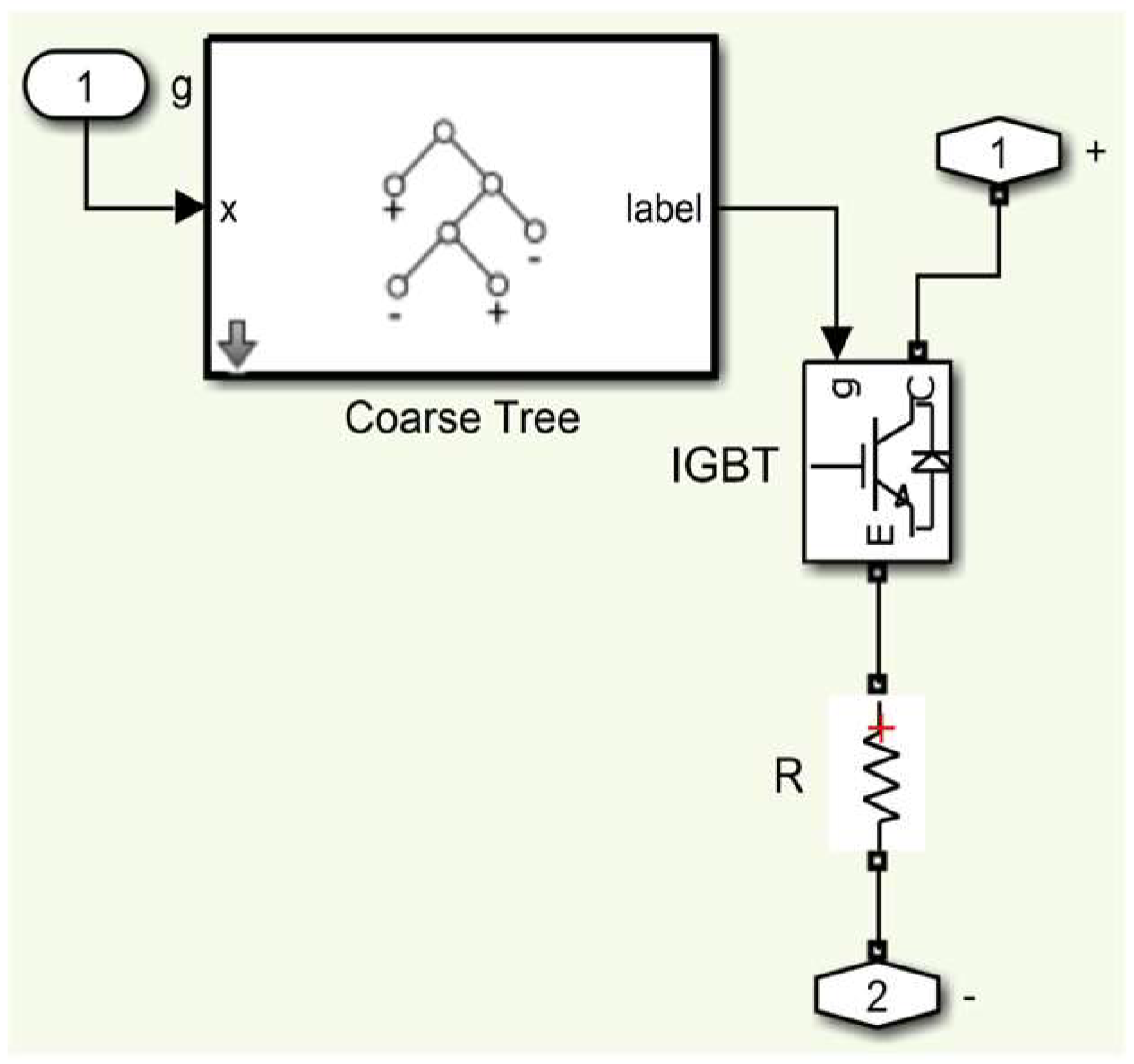
The DC chopper is widely used in the literature for fault current protection systems of grid-connected PVPP systems. The DC chopper circuit is placed between a T-type inverter and a PV panel. The DC chopper topology for the PVPP system is given in
Figure 2. A DC chopper circuit includes an IGBT and a very small DC resistor connected in series with it. A DC chopper operates through the gate opening and closing signals of the IGBT. A trigger signal is given to the IGBT to protect the PV panels against damage caused by the fault occurring in the electric power grid. Therefore, the protection circuit is activated and protected from the harmful effects of overcurrent. In this study, a DC chopper control system is defined as an ML algorithm. The DC bus voltage value is measured in real time and is defined as the input of the ML algorithm. A switching signal of the semiconductor switching element in the DC chopper is an output of the ML method. In this study, the output voltage value (
Vdc) of the PV panel system is set as 481. The ML algorithm detects the fluctuation in the
Vdc voltage value and generates output signals. After the grid fault is cleared, a well-designed procedure is applied to generate PV panel voltage and quickly restart the T-type inverter. A DC chopper circuit is closed by an ML algorithm when the grid voltage returns to a normal level. The design of a DC chopper is illustrated in
Figure 2.
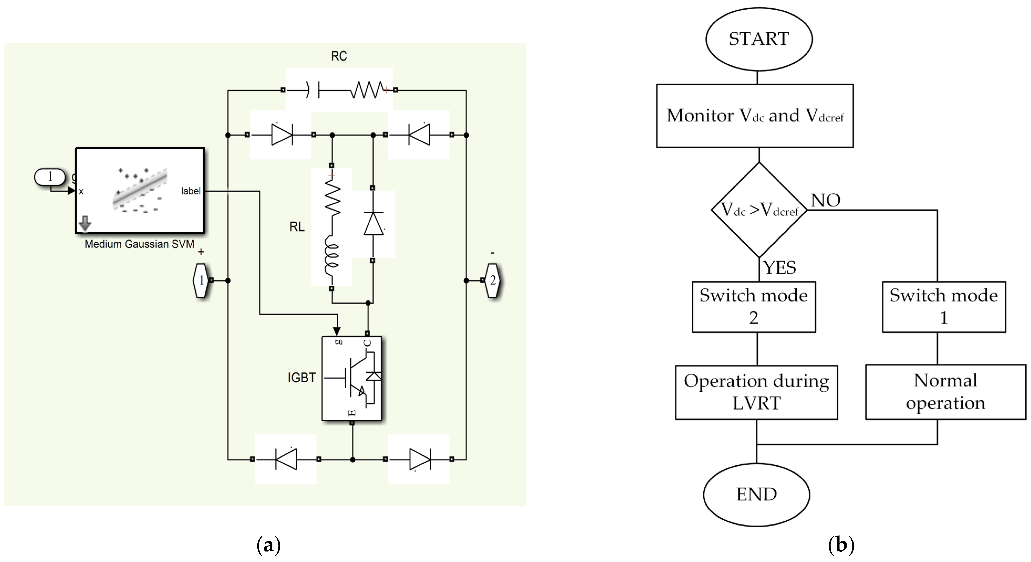
The design of a capacitive bridge fault current limiter with a machine learning technique and a flowchart of the proposed control algorithm are illustrated in
Figure 3a,b, respectively. CBFCL is designed to protect the electrical network from the harmful effects of high voltage and current generated during faults in energy transmission and distribution networks. The structure of CBFCL consists of a control system and an electronic circuit. The control system of CBFCL continuously measures the voltage, current, and frequency of the PV system and continuously monitors the operation of the PV system. These control systems detect fault conditions occurring in electric energy systems and then regulate the signals of electronic switching elements. CBFCL’s electrical circuit comprises two circuits: shunt and bridge. The control system generates the switching signal for the IGBT. The IGBT’s switching signal value is 1 when the PV system is operating normally. The system’s line current passes via the bridge portion because the semiconductor switch is closed. The IGBT switching signal value is zero when the PV system is operating faultily. The semiconductor switch is open, and the system’s line current flows through the shunt component. The shunt circuit is made up of impedance-matched resistors and capacitors. As a result, the shunt component controls the high current during the fault time, protecting the PV system from the negative consequences of the high current. In addition, CBFCL reduces voltage fluctuations throughout the fault time.
In the literature, traditional control methods are widely used in the protection system against the fault current of the grid-connected PVPP system. The ML algorithm provides an intelligent way to overcome the variables that harm the PV panel system. At the same time, traditional protection techniques struggle to reduce the causes that can cause damage during the fault time. In this study, the output voltage value (Vdc) of the PV panel system is set to 481.
The machine learning method used in this study is the supervised learning approach. Supervised learning is trained with labeled data and makes predictions for new inputs. This study uses the Classification Learner Toolbox tool in MATLAB 2022b to test and compare the performance of several classification algorithms, including Tree, SVM, KNN, and Ensemble. Each of the classification methods has different classifier functions. The SVM algorithm has Coarse Gaussian, Medium Gaussian, Fine Gaussian, Cubic, Quadratic, and Linear classifier functions. The ML model is developed to classify different operating conditions of the grid-connected PVPP system. The input of the model is defined as the DC-link voltage, and the output is defined as the switching signal of the semiconductor. During the training process, the model is trained using the labeled dataset, and the obtained predictions are compared with the actual target values, and their accuracy is analyzed. To evaluate the performance of the model, accuracy, precision, recall, and F1-score are calculated. Each metric is obtained using the following formulas:
The DC-link voltage value is measured in real time and defined as the input of the ML algorithm. The ML algorithm minimizes and predicts the oscillations and faults of the power grid, thus improving the stability of the system. Also, the output of the ML approach is described as the switching signal of the semiconductor switching element in CBFCL. The ML algorithm detects and generates output signals when there is a fluctuation in the
Vdc voltage value [
34].
3. Proposed System for Improving the LVRT Capability of a PV Power Plant
The proposed hybrid protection system block of the 250 kW PVPP based on the ML approach is given in
Figure 4. Modelling and control of 250 kW PVPP has been performed. The PVPP system is connected to the grid via a T-type inverter. The T-type inverter converts the DC voltage produced by the PV panel to AC voltage. A capacitor is placed between this inverter and the PV panel. The SPWM method controls the switching signals of the DA/AC inverter. MOSFET is used as the switching element in the DA/AC inverter.
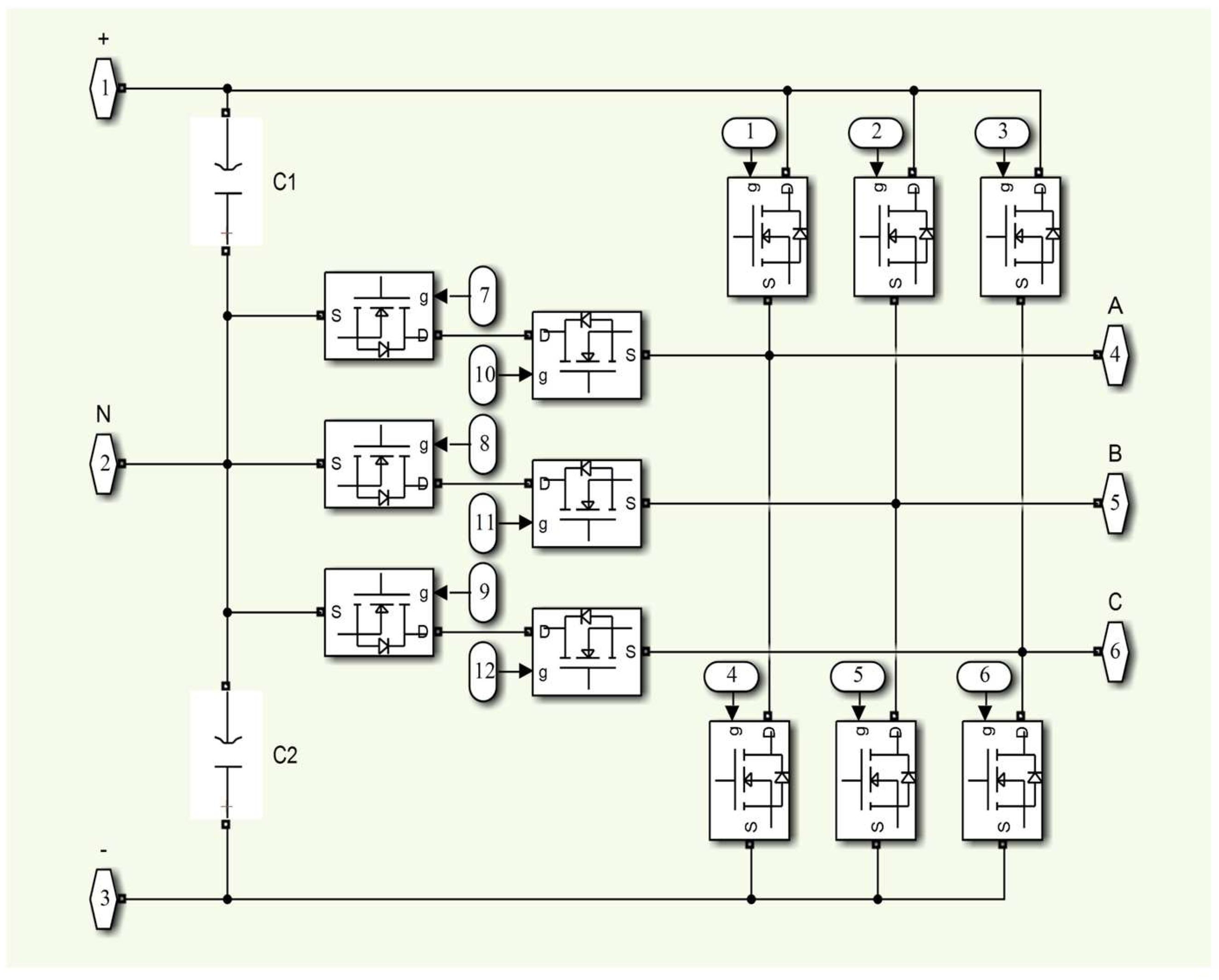
Using a DC-DC converter in the system has several disadvantages. First, the DC-DC converter causes switching and conduction losses. Second, the DC-DC converter complicates the system architecture. Third, the DC-DC converter increases both the implementation costs and maintenance complexity. Therefore, in this study, the series connection of seven PV modules was chosen instead of a front-end DC-DC converter. Moreover, a direct series-connected PV array provides faster dynamic response compared to a system with a DC-DC converter during LVRT events. Voltage regulation is frequently delayed when using a DC-DC converter. T-type inverters have become more advantageous than two-level converters, producing a better output signal. The semiconductor switches in the high-level inverter operate more efficiently because they perform at lower voltages. The THD value decreases when the number of levels increases. In other words, the output voltage’s THD value is zero when there are infinite levels. However, as the number of levels increases, the control of the inverter becomes more difficult, and an imbalance is observed in the output voltage. In this study, the simulation circuit of the three-phase T-type inverter in the Matlab 2022b/Simulink program is given in
Figure 5. The operating conditions of the designed three-phase T-type inverter are examined. Switching signals are generated using the sinusoidal pulse width modulation (SPWM) technique. The SPWM technique is a technique widely used for industrial inverters. The SPWM technique is one of the frequently used techniques that minimizes harmonics in square wave signals. The intersection points for switching times are determined by comparing the reference and carrier waves. The reference signal is a sine wave with peak differences and frequency. A triangular waveform is usually used as the carrier signal.
The output voltage values of the single-phase three-level converter are illustrated in
Table 2, according to the switching status. The switches are in conduction when they are in the 1 position. The switches are in the cut-off position when they are in the 0 position. As can be seen from
Table 2, the
Van voltage takes three different values.
To control the PVPP system, mathematical equations must be known. This mathematical model facilitates learning the transient and steady-state characteristics of the PV panel. The Clarke and Park transforms are a transformation used to simplify the analysis of three-phase circuits. The Clarke transform transforms the three-phase system (abc) into a fixed two-phase reference system (αβ) and the Park transform transforms the fixed two-phase reference system (αβ) into a direct quadrature (dq) system. The fixed two-phase reference frame obtained via the Clarke transform is used when performing the Park transform.
The current of the three-phase system measured in the network is converted to the dq system using the Clark and Park transformations. The control unit of the PVPP system consists of id and iq axes. The input of the Id axis is the Vdc voltage. Then, 481 V is selected as the Vdc reference value. The Vdc voltage is always measured and compared with the Vdc reference voltage value. As a result of this comparison, the error Vdc voltage is obtained. This error value is the input value of the DC-link control.
4. Simulation Results
Three different LVRT cases are analyzed in a 250 kW grid-connected PVPP model using Matlab/Simulink. The 250 kW grid-connected PVPP model consists of a PV panel, a T-type inverter, a transformer, and various values, as illustrated in
Figure 4. The DC-link voltage and solar irradiation values are kept constant at 481 V and 1000 W/m
2, respectively. In this study, a DC chopper and CBFCL based on the ML algorithm are applied to regulate the performance of three different LVRT cases in a 250 kW grid-connected PVPP model. The ML control system for the two protection systems is designed for improved LVRT operation. The values of the parameters of the 250 kW grid-connected PVPP model are illustrated in
Table 3.
MATLAB Classification Learner Toolbox has four classification methods, which are named Tree, SVM, KNN, and Ensemble. These classification methods also have many classifiers. In this study, 3001 data points are randomly selected for the fault and normal conditions of the PVPP system. The obtained data are used to train 20 classifier methods separately. As a result of the training, accuracy, TPR, FPR, recall, precision, and F1-score values are obtained, and these are given in
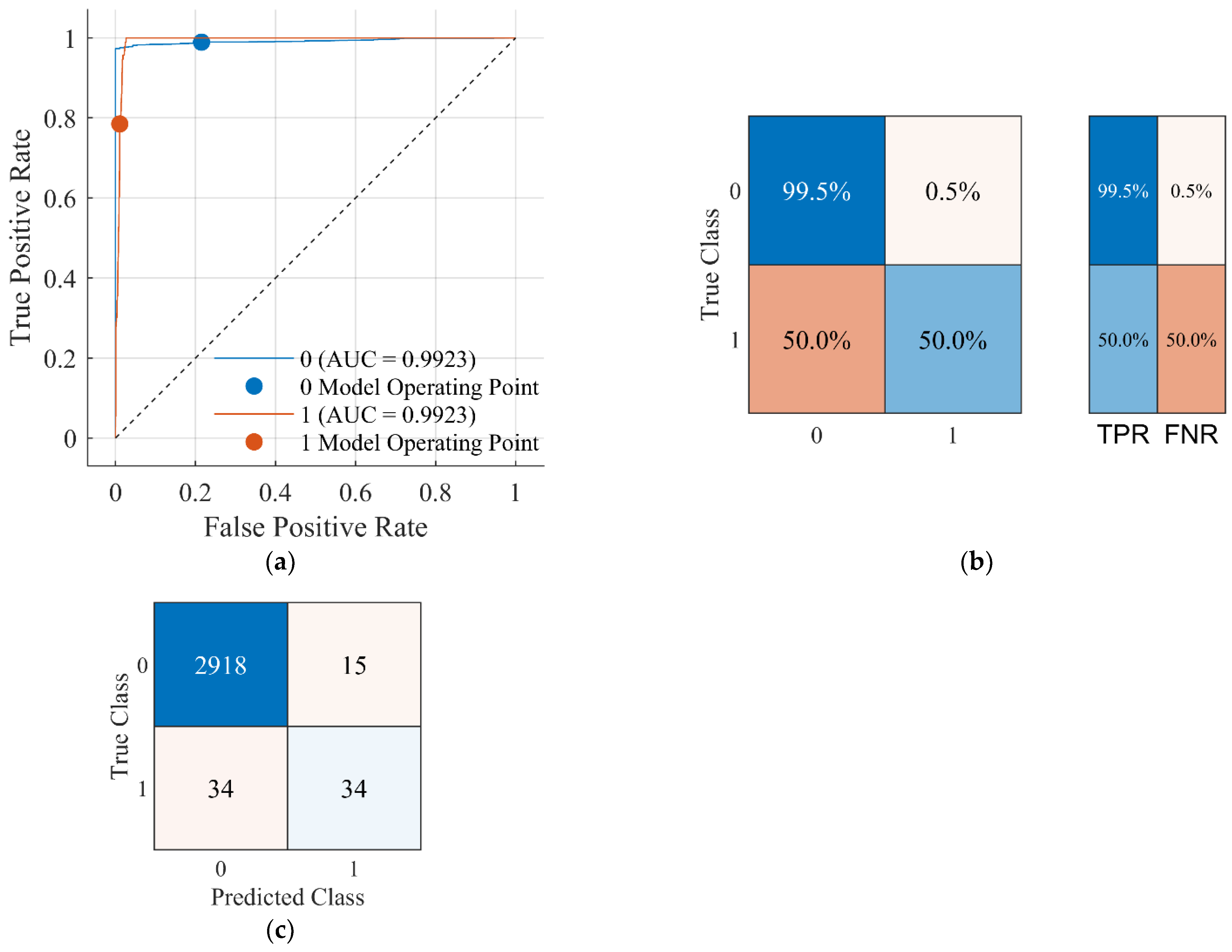
Table 4. Among the 20 classifier algorithms, the Coarse Tree classifier has the best accuracy (98.31%), TPR (98.9%), FPR (78.5%), precision (99.31%), and F1-score (99.12%) for the DC chopper protection system. Therefore, the Coarse Tree classifier is selected for the DC chopper protection system and applied to the control of the protection system. Classification accuracy using a Coarse Tree for the grid-connected PVPP system is illustrated in
Figure 6.
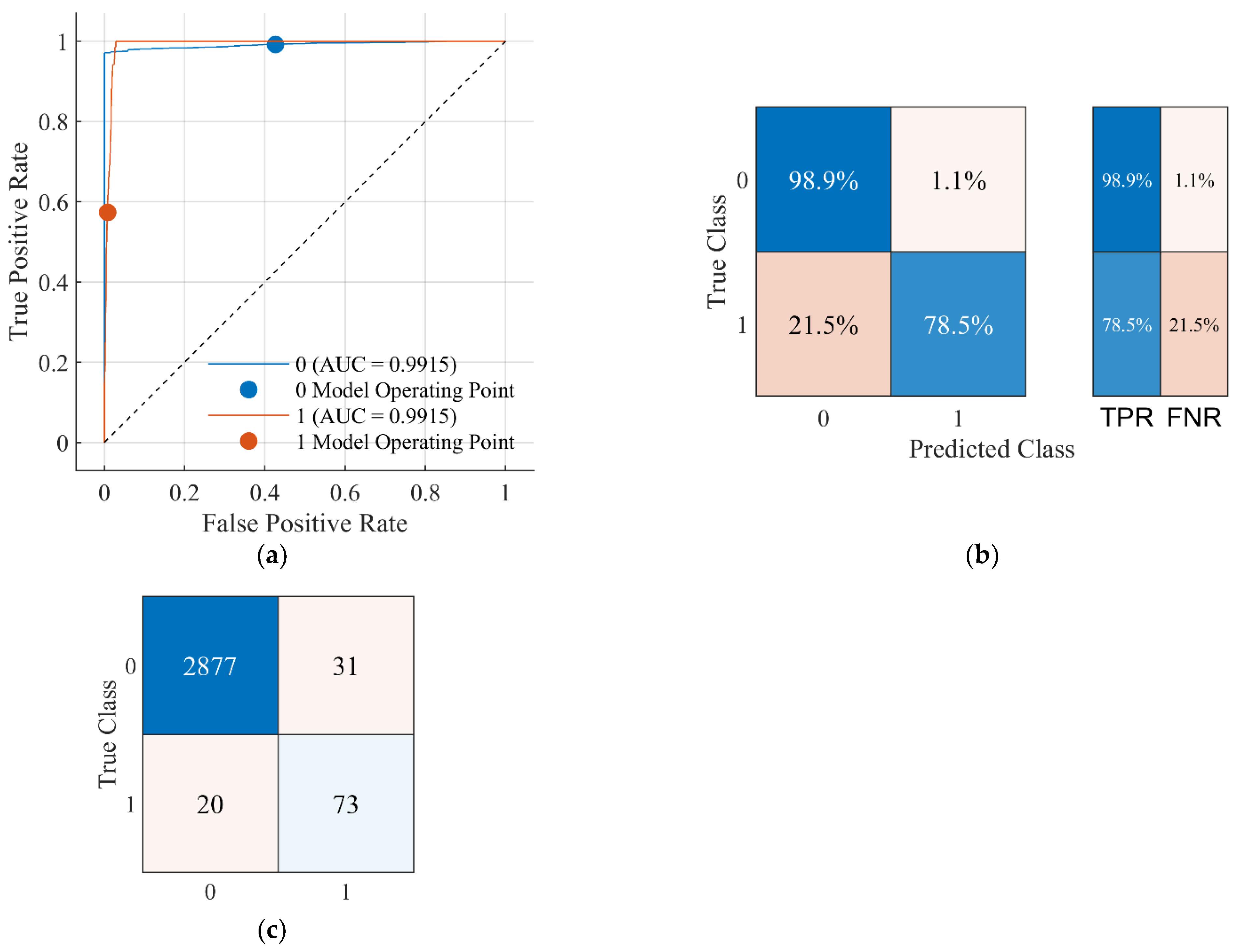
Accuracy, TPR, FPR, recall, precision, and F1-score values are given in
Table 5. In this study, 3001 data points are randomly selected for the fault and normal conditions of the PVPP system. The obtained data are used to train 20 classifier methods separately. Among the 20 classifier algorithms, the Medium Gaussian SVM classifier has the best accuracy (98.37%) and F1-score (99.17%) for the DC chopper and CBFCL protection system. Therefore, the Medium Gaussian SVM classifier is selected for the DC chopper protection system and applied to the control of the protection system. Classification accuracy using the Medium Gaussian SVM for the grid-connected PVPP system is illustrated in
Figure 7.
4.1. Scenario 1
The Tree classifier is implemented in the control system of the DC chopper protection method (DCch + Tree). The SVM classifier is used in the control system of DC chopper and CBFCL protection method (DCch + CBFCL + SVM). In this study, these methods will be referred to as DCch-based Tree and DCch + CBFCL-based SVM, respectively. For the grid-connected PVPP system, DCch-based Tree and DCch + CBFCL-based SVM protection techniques are employed separately, with the results shown in
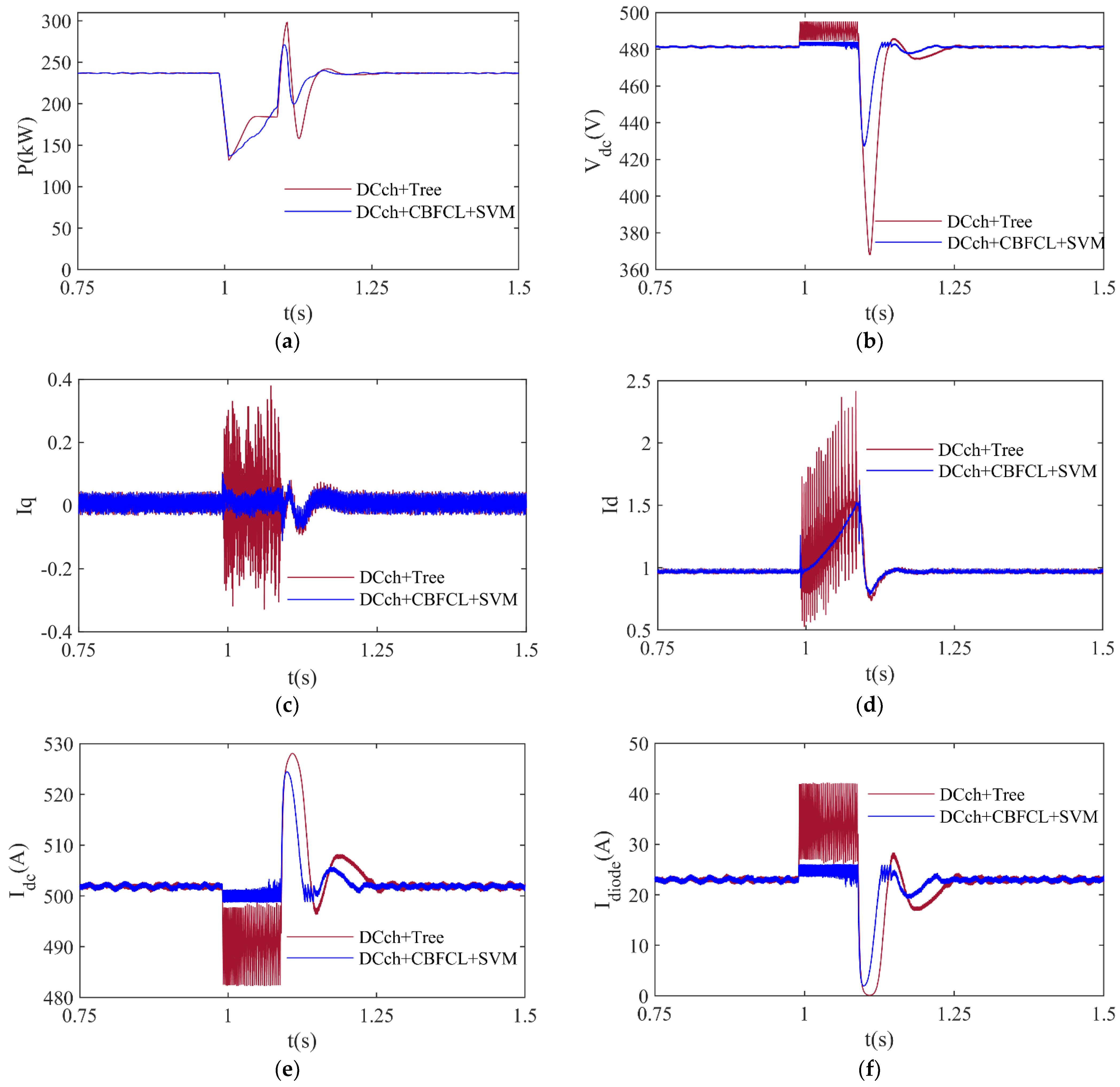
Figure 8. In this study, a voltage dip of 90% is simulated between t = 1 s and 1.1 s, representing typical voltage dip duration time in grid systems. A voltage dip of 90% in electrical power grids is known as the least frequent type of voltage dip, but it is a serious situation compared to other types of voltage dip. Therefore, it is quite difficult to control this voltage dip during LVRT. For minimizing the negative impacts of a voltage dip of 90%, the DCch-based Tree and DCch + CBFCL-based SVM protection approaches are employed. The active power fluctuations produced by the PVPP system during a voltage drop of 90% are illustrated in
Figure 8a. The active power produced by a PVPP system under normal operating conditions is 237 kW. When the PVPP system employs the DCch-based Tree approach, its active power peak is 284.63 kW and, after a 90% voltage decrease, its lowest active power value is 25.49 kW. When compared to the outcomes of another protection technique, the PVPP system’s peak and lower active power values employing the DCch + CBFCL-based SVM approach have the best values. A PVPP system’s DC-link voltage value during a 90% voltage loss is shown in
Figure 8b. During normal operation, a PVPP system’s DC-link voltage is 481 V. The PVPP system’s DC-link voltage, as determined using the DCch-based Tree technique, has a maximum value of 495.32 V and a minimum value of 380.85 V during a 90% voltage drop. When compared to the results of another protection method, the PVPP system’s peak and lowest DC-link voltage levels utilizing the DCch + CBFCL-based SVM approach have good values.
Figure 8c–f show the changes in q-axis current (
Iq), d-axis current (
Id), DC current (
Idc), and the diode current (
Idiode) of the PVPP system, respectively. Current values for
Iq and
Id are set to 1 and 0, respectively. During normal operation, the PVPP system’s nominal DC current is 500 A, and the diode current is 23 A.
Table 6 compares the effectiveness of both protection techniques for a 90% voltage dip. The analysis of the current waveforms in
Figure 8c–f demonstrates that the DCch + CBFCL-based SVM approach enhances active power regulation by maintaining the
Iq and
Id currents near their nominal values and offers more stable inverter operation by lowering DC current variations. It is observed that the proposed protection method significantly reduces
Idc current fluctuations. As a result, it prevents the inverter from overloading and unstable operation by preventing sudden changes to input current in the inverter. In addition, it is seen that the DCch + CBFCL-based SVM method minimizes the overcurrent conditions and ensures that the inverter protection mechanisms work more effectively when the diode current (
Idiode) is analyzed. The simulation results demonstrate that the proposed protection method provides more effective current regulation during LVRT operation.
4.2. Scenario 2
For the grid-connected PVPP system, DCch-based Tree and DCch + CBFCL-based SVM protection techniques are employed separately, with the results shown in
Figure 9. In this study, a voltage dip of 50% is simulated between t = 1 s and 1.1 s, representing the typical voltage dip duration time in grid systems. A 50% voltage dip in an electrical power grid is a medium-severity fault condition. For minimizing the negative impacts of a voltage dip of 50%, the DCch-based Tree and DCch + CBFCL-based SVM protection approaches are employed. The active power fluctuations produced by the PVPP system during a voltage drop of 50% are given in
Figure 9a. When the PVPP system employs the DCch + CBFCL-based SVM approach, its active power peak is 271.34 kW and, after a 50% voltage decrease, its lowest active power value is 137.08 kW. When compared to the outcomes of another protection technique, the PVPP system’s peak and lower active power values employing the DCch + CBFCL-based SVM approach have the best values. A PVPP system’s DC-link voltage value during a 50% voltage loss is shown in
Figure 9b. During normal operation, a PVPP system’s DC-link voltage is 481 V. The PVPP system’s DC-link voltage, as determined using the DCch + CBFCL-based SVM technique, has a minimum value of 427.03 V and a maximum value of 484.14 V during a 50% voltage drop. When compared to the results of another protection method, the PVPP system’s peak and lowest DC-link voltage levels utilizing the DCch + CBFCL-based SVM approach have good values.
Figure 9c–f show the changes in q-axis current (
Iq), d-axis current (
Id), DC current (
Idc), and the diode current (
Idiode) of the PVPP system, respectively. Current values for
Iq and
Id are set to 1 and 0, respectively. During normal operation, the PVPP system’s nominal DC current is 500 A, and the diode current is 23 A.
Table 7 compares the effectiveness of both protection techniques for a 50% voltage dip. The analysis of current waveforms in
Figure 9c–f demonstrates the effect of DCch-based Tree and DCch + CBFCL-based SVM methods on current responses during the LVRT process. The q-axis current
Iq and d-axis current
Id control the active power and DC-link voltage of the grid-connected PV system, respectively. The DCch + CBFCL-based SVM method reduces the fluctuations in active power value by keeping the
Iq current closer to the nominal value during a voltage dip. The DCch + CBFCL-based SVM method reduces the fluctuations in the DC-link voltage value by keeping the Id current close to zero level. The proposed method significantly reduces the fluctuations in DC current (
Idc). It prevents overloading and unstable operation of the inverter by preventing sudden changes in the inverter input current. Diode current is a critical parameter for the protection circuits of an inverter. Long-term hardware problems and thermal stress in the inverter components are avoided by managing excessive diode current. As a result, it helps the system to provide more stable operation by increasing its contribution to the grid during the LVRT process.
4.3. Scenario 3
For the grid-connected PVPP system, the DCch-based Tree and DCch + CBFCL-based SVM protection techniques are employed separately, with the results shown in
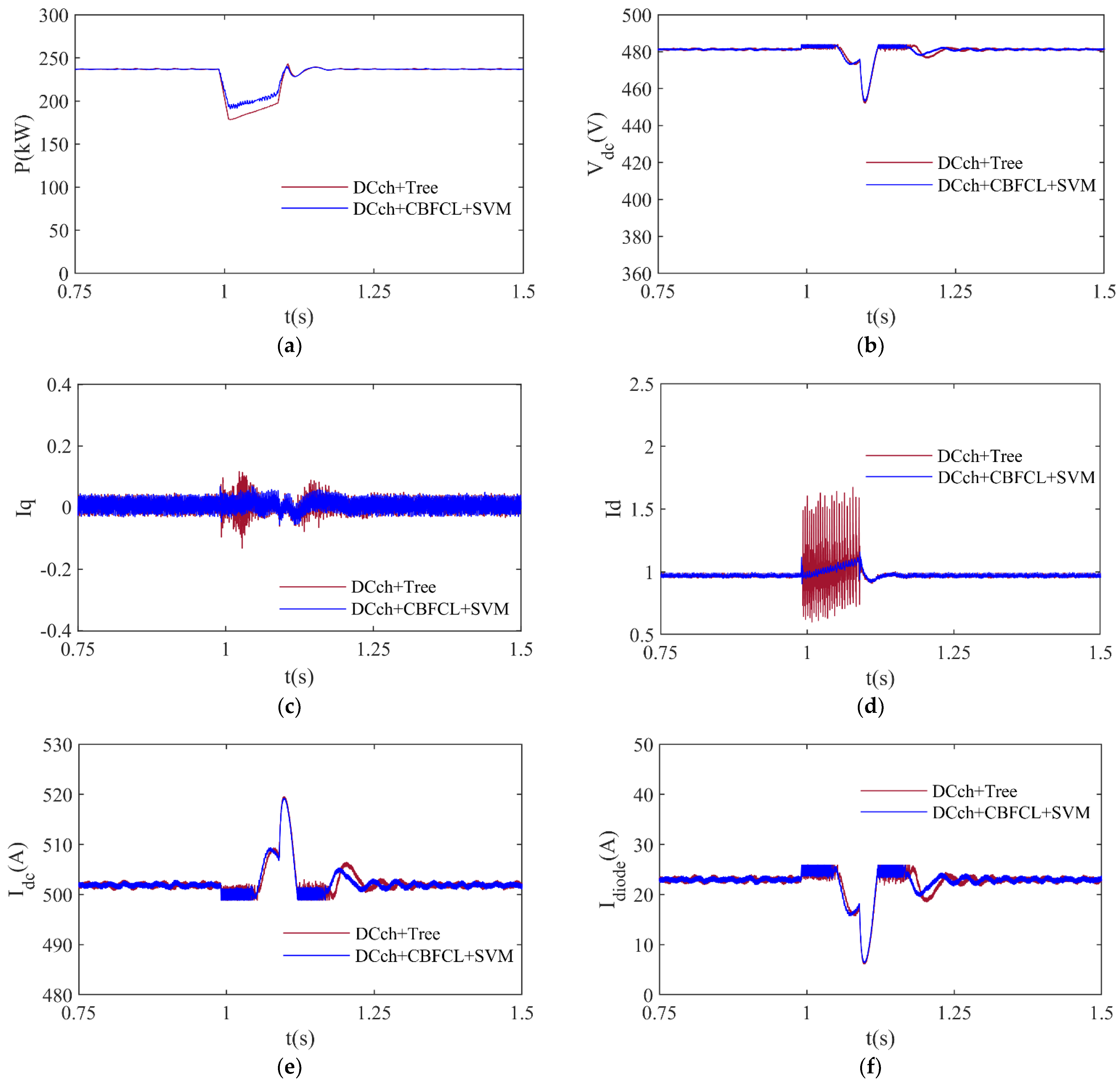
Figure 10. In this study, a voltage dip of 25% is simulated between t = 1 s and 1.1 s, representing typical voltage dip duration time in grid systems. A 25% voltage dip is the most common voltage dip type in an electrical power grid. Therefore, it is a more serious situation than other voltage dips. For minimizing the negative impacts of a voltage dip of 25%, the DCch-based Tree and DCch + CBFCL-based SVM protection approaches are employed. The active power fluctuations produced by the PVPP system during a voltage drop of 25% are given in
Figure 10a. The PVPP system employs the DCch-based Tree approach, and its active power peak is 243.31 kW. The PVPP system employs the DCch + CBFCL-based SVM approach, and its active power peak is 240.46 kW. The PVPP system employs the DCch-based Tree approach, and its active power is the lowest, at 178.17 kW. The PVPP system employs the DCch + CBFCL-based SVM approach, and its active power is the lowest, at 190.41 kW. The PVPP system, using the DCch + CBFCL-based SVM strategy, has the best peak and lowest active power levels when compared to the results of another protection technique. A PVPP system’s DC-link voltage value during a 25% voltage loss is shown in
Figure 10b. The PVPP system’s DC-link voltage, as determined using the DCch + CBFCL-based SVM technique, has a minimum value of 427.03 V and a maximum value of 484.14 V during a 25% voltage drop. The PVPP system employs the DCch-based Tree technique, and its active power peak is 484.11 V. The PVPP system employs the DCch + CBFCL-based SVM technique, and its DC-link voltage peak is 484.06 V. The PVPP system employs the DCch-based Tree technique, and its DC-link voltage is the lowest, at 452.05 V. The PVPP system employs the DCch + CBFCL-based SVM technique, and its DC-link voltage is the lowest, at 452.99 V. The peak and lowest DC-link voltage levels of the PVPP system using the DCch + CBFCL-based SVM methodology exhibit good values when compared to the outcomes of another protection method.
Figure 10c–f show the changes in q-axis current (
Iq), d-axis current (
Id), DC current (
Idc), and the diode current (
Idiode) of the PVPP system, respectively. Current values for
Iq and
Id are set to 1 and 0, respectively. During normal operation, the PVPP system’s nominal DC current is 500 A, and the diode current is 23 A.
Table 8 compares the effectiveness of both protection techniques for a 25% voltage dip. As shown in the analysis of current waveforms in
Figure 10c–f, the proposed DCch + CBFCL-based SVM method improves active power and DC-link voltage control by making current waveforms more stable during LVRT, increases system stability by reducing inverter input current fluctuations, and supports safe operation of the equipment by preventing overcurrent conditions. As a result, it is shown that the proposed method improves the LVRT performance, ensuring more reliable and efficient operation of grid-connected PV systems.
The DCch-based Tree protection method has higher ripples than the DCch + CBFCL-based SVM protection method due to the inherent limitations of the response of the DC chopper during a voltage dip, as shown in
Figure 8,
Figure 9 and
Figure 10. The rapid fluctuations in voltage and current values occur when it experiences a sharp voltage dip on the grid. The DCch-based Tree cannot completely compensate for these rapid fluctuations on the grid, which causes low-frequency oscillations due to the finite response time and switching characteristics of the DC chopper.
5. Conclusions and Future Work
In this study, an ML control method is developed specifically for grid-connected PV systems by training with data obtained by analyzing different grid states and conditions. In order to forecast the best control parameters using real time, including both fault and normal operation conditions of the grid-connected PVPP system, the ML approach is trained on historical data. Individual ML methods are modified to generate a hybrid protection technique and a DC chopper. A hybrid protection technique using the ML control approach has been successfully established, effectively reducing the impacts of three voltage dip types: 90%, 50%, and 25%. Among 20 classifier algorithms, the Coarse Tree classifier has the best accuracy (98.31%), TPR (98.9%), FPR (78.5%), precision (99.31%), and F1-score (99.12%) for the DC chopper protection system. The Medium Gaussian SVM classifier has the highest accuracy (98.37%) and F1-score (99.17%) for the DC chopper and CBFCL protection method among the 20 classifier methods. These values increase component compatibility by ensuring that the components used in the system perform best within a certain operating range; this helps the system operate more stably and reliably. When compared to the findings of another protection technique, the grid-connected PVPP system’s DC-link voltage peak and lowest values utilizing the hybrid protection-based SVM approach are good values. Furthermore, when compared to the outcomes of other protection techniques, the hybrid protection-based SVM method provided the best settling time values for the grid-connected PVPP system in all of the tests. The effectiveness of the presented hybrid protection system shows the remarkable ability of ML approaches to precisely detect voltage dips and dynamically modify CBFCL to safeguard a grid-connected PVPP system under various voltage conditions.
One of the main challenges of the proposed method is the long training time of the ML model. In addition, the ML model has a complex computational resource structure. Its implementation in real-world applications requires high computational power and advanced control systems, and this approach improves the stability of a grid-connected PVPP system. Therefore, all the scenarios needed for real-world studies may not have been available for this study.
Future research should focus on overcoming these limitations by exploring more efficient ML algorithms that require less computational resources. It would be valuable to investigate alternative power electronics solutions and cost-reduction strategies for real-world applications. It would also be important to investigate the long-term stability and reliability of the performance of the grid-connected PVPP system under various grid conditions.


