Anchoring Effect of Abandoned Oil Wells in Coal, Oil, and Gas Co-Production Areas and Its Influence on Overburden Stability

 , , , ,
Abstract
1. Introduction
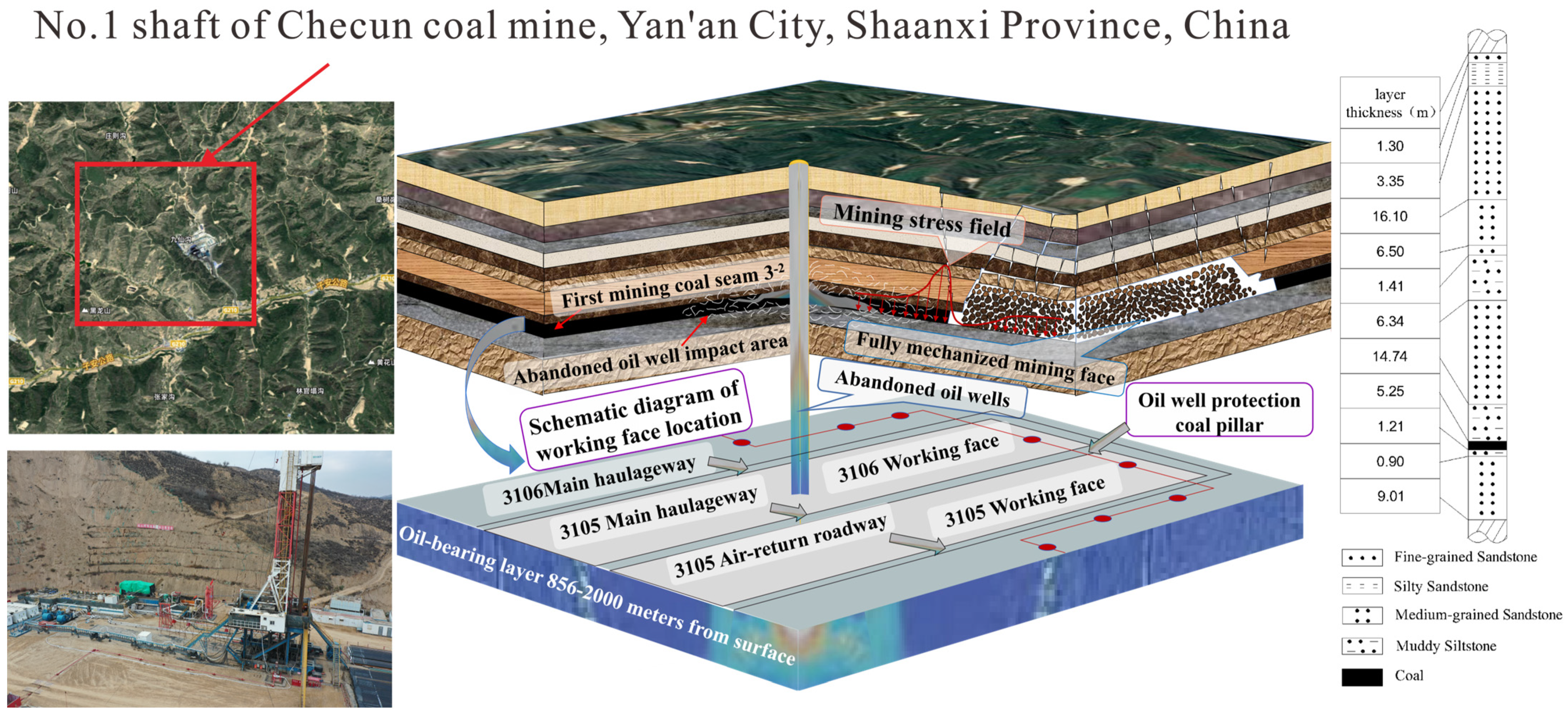
2. Project Overview
3. Theoretical Analysis of the Anchoring Action of Oil Wells on the Movement of Overburden Rock
3.1. Mechanisms Affecting Anchoring in Oil Wells
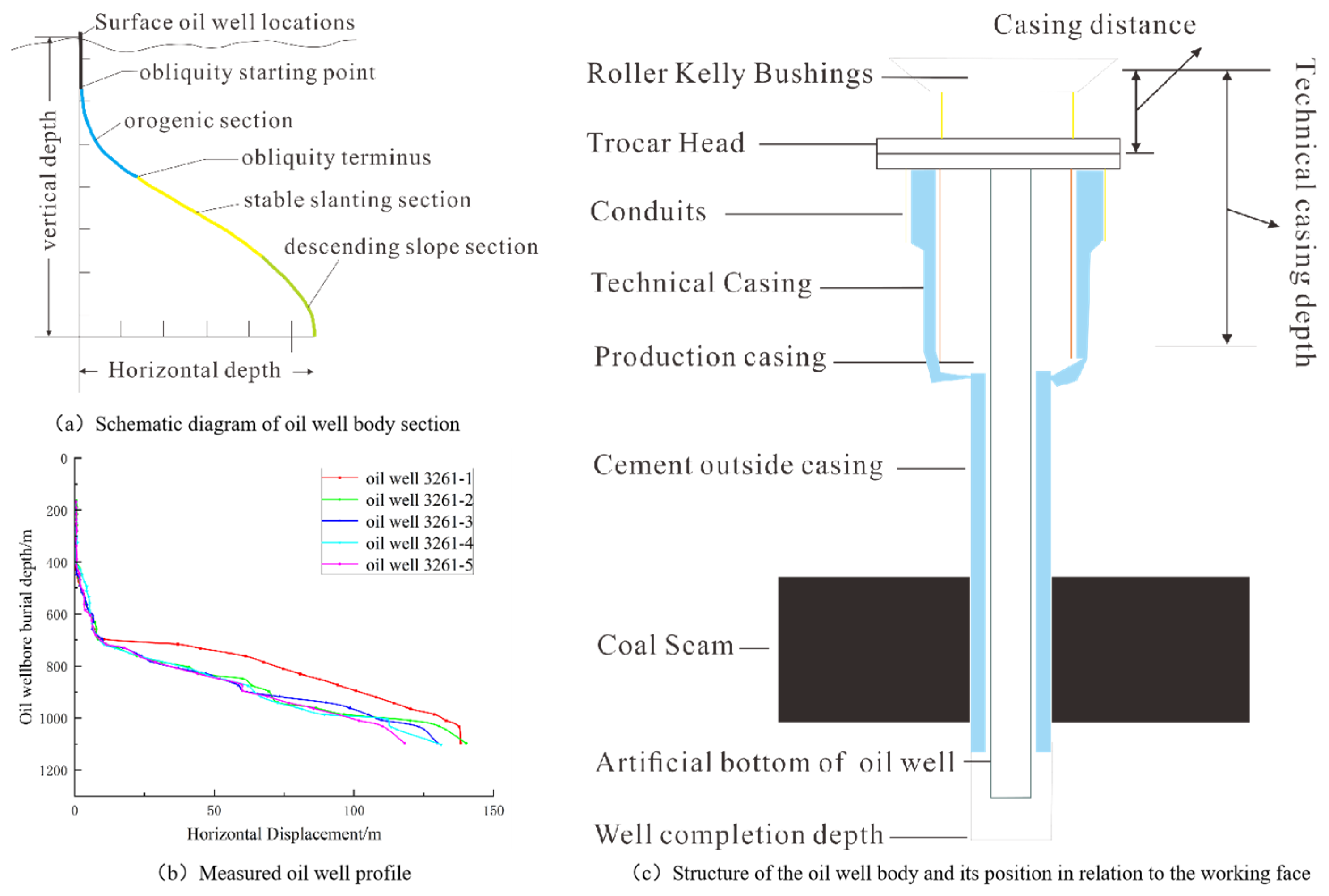
3.2. Mechanics of Oil Wells in the Formation
3.2.1. The Influence of Oil Wells on the Angle of Internal Friction of Surrounding Rock Formations
3.2.2. The Effect of Oil Wells on the Cohesion of the Rock Formations Surrounding Them
3.2.3. Effect of Oil Well Casing on the Compressive Strength of the Rock Formation Surrounding It
3.2.4. The Effect of Oil Well Casing on the Modulus of Elasticity of the Rock Formation Surrounding It
3.3. Stability Analysis of Overlying Rocks Under Anchorage
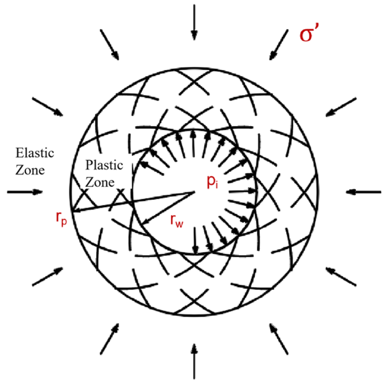
3.3.1. Borehole Plasticity Zone Range
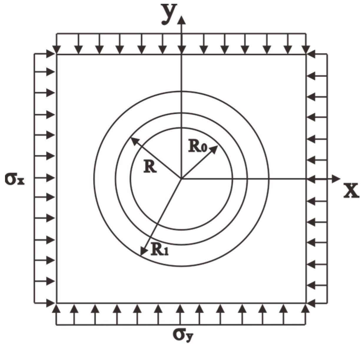
3.3.2. Overburden Stress Analysis
3.3.3. Stability Analysis of Overburden
- (1)
- Stability analysis of layered rocks
- (2)
- Factor of Safety for overburden instability analysis
4. Numerical Simulation Study of the Effect of Anchoring on Overburden Rock in Oil Wells
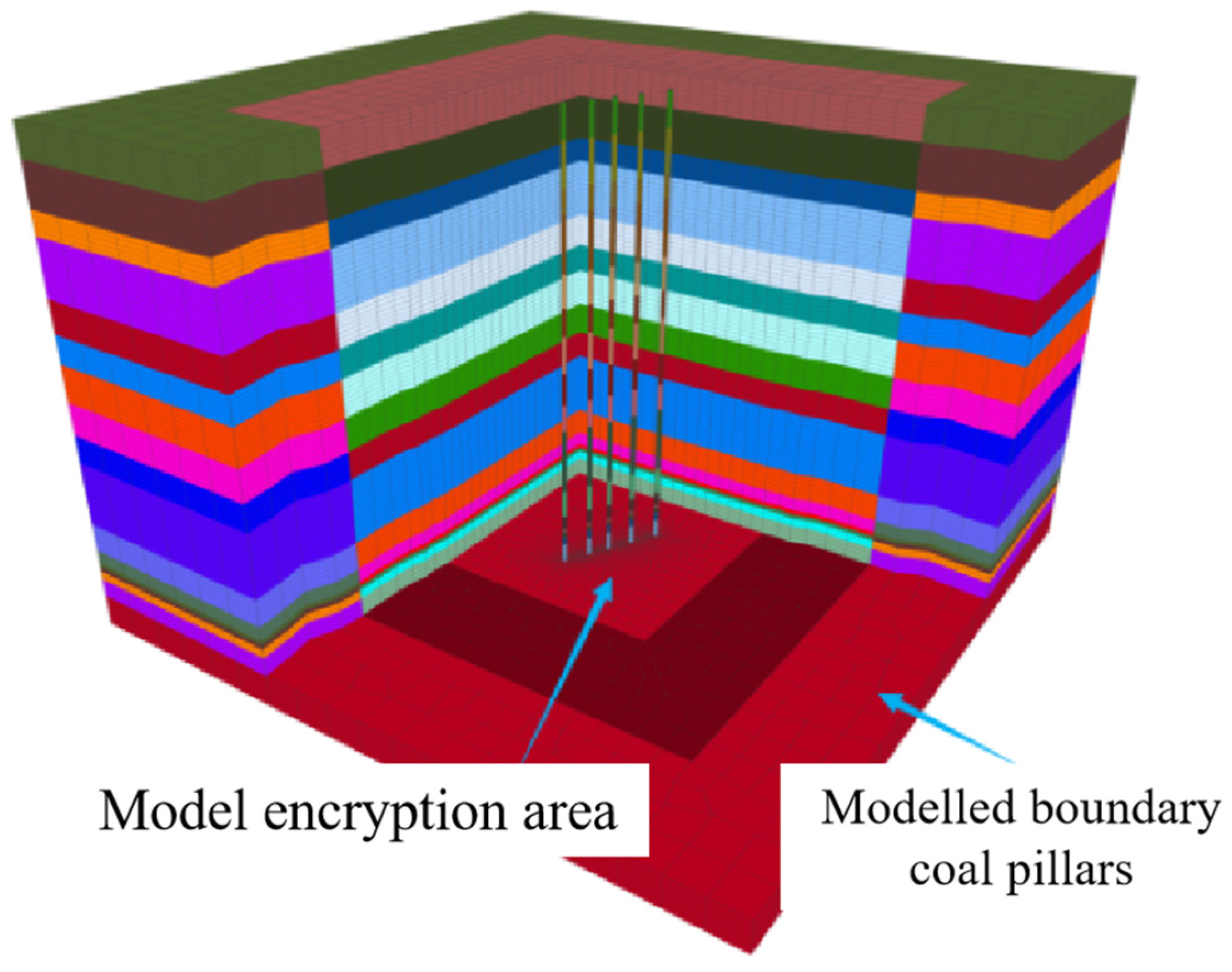
4.1. Modeling and Scenarios
4.2. Analysis of Oil Wells Within a Cluster of Wells with Different Burial Depth Pairs
- (1)
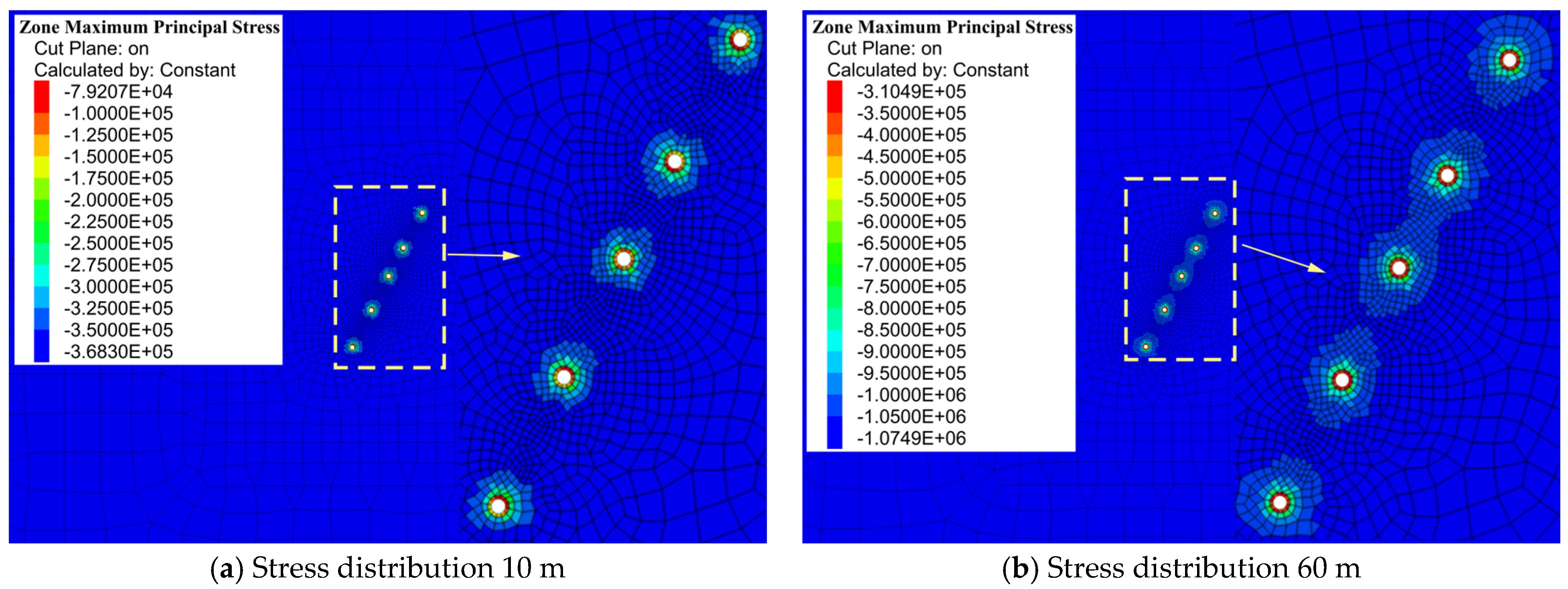
- Stress changes in oil wells at different burial depths
- The peak stress increases with increasing burial depth.
- At a burial depth of 10 m, the peak stress around the oil well is only 0.37 MPa, with a stress concentration range of less than 1.2 m.
- At a burial depth of 105 m, the peak stress rises to 2.24 MPa, while the stress concentration range expands to 4 m, and the stress concentration zone contracts toward the well wall.
- At shallow depths (10–60 m), no significant stress overlap is observed between wells.
- At greater depths (90–105 m), neighboring well stress fields exhibit superposition effects, leading to an expansion of the stress concentration zones.
- (2)
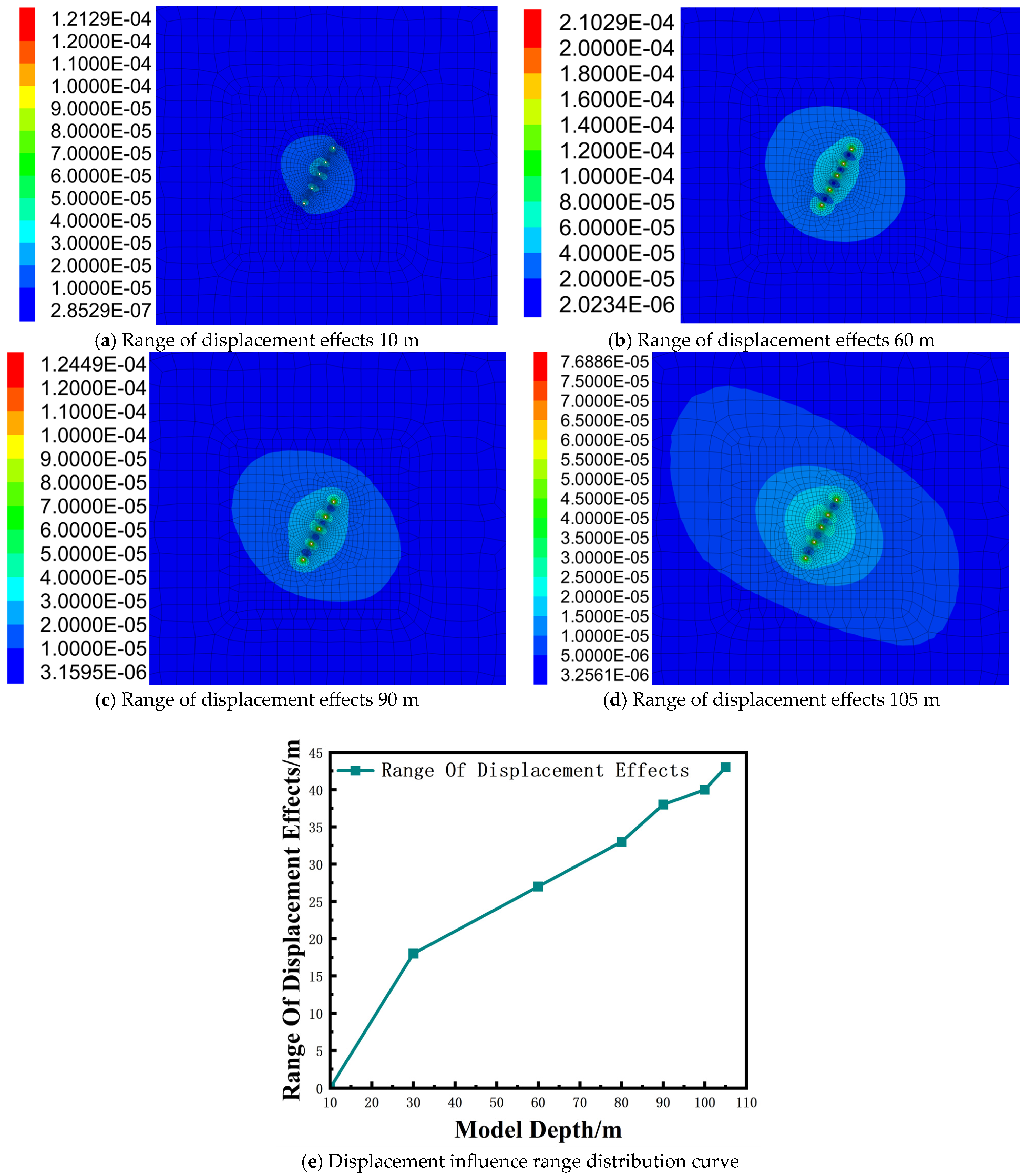
- Displacement changes in oil wells at different burial depths
- At a burial depth of 30 m, the displacement influence range is 18 m.
- At a burial depth of 105 m, the displacement influence range expands to 41 m, indicating a larger affected zone and an enhanced constraining effect of the oil well.
- (3)
- Changes in plastic zone of oil wells under different burial depths
- The plastic zone remains limited in extent under all burial depth conditions, ranging between 0.9 m and 1.6 m.
- At a burial depth of 105 m, the plastic zone reaches its maximum extent of 1.6 m but does not exhibit significant penetration-induced damage.
- The plastic zone is primarily localized around the wellbore, with no overlap between plastic zones of adjacent wells, suggesting the absence of stress coupling effects between neighboring wells.
5. Conclusions
- The stress field distribution characteristics of a single oil well in the formation were theoretically calculated, revealing that the plastic zone radius extends to 1.43 m. A mechanical analysis of the casing and cementing cement demonstrated that their primary function is to enhance the cohesion of the rock mass and increase the internal friction angle. After casing anchorage, the cohesion of the surrounding rock increased by 5.51 MPa, while the increment in the internal friction angle was negligible. The casing anchorage mechanism improves the compressive and shear strength of the rock mass and modifies its elastic modulus and Poisson’s ratio. Within the plastic zone, the uniaxial compressive strength of the casing-anchored solid increased by 23.06 MPa, the elastic modulus reached 13.245 GPa, and Poisson’s ratio was 0.257. These findings indicate a significant reinforcement effect of casing anchorage on the surrounding rock mass, contributing to enhanced stability and mechanical performance.
- Based on the FLAC3D 7.0 numerical model, the stress peak around the oil wells gradually increases with burial depth, rising from 0.37 MPa to 2.24 MPa. Simultaneously, the displacement influence range of the oil well cluster in each monitored stratum also exhibits a progressive expansion, extending from 18 m to 43 m. Furthermore, the subsidence displacement of the rock strata in proximity to the oil wells is significantly smaller compared to that of more distant formations, indicating that oil wells exert a restraining effect on stratum subsidence. These findings underscore the mechanical stabilization role of oil wells in mitigating excessive deformation within the surrounding strata.
- Oil well anchoring technology ensures well wall stability by regulating stress distribution, supporting the overburden, and enhancing the compressive and shear strength of the well structure. Through the synergistic effect of cementing and casing support, the anchoring system effectively mitigates the risk of well wall instability. The oil well casing functions analogous to an embedded anchor within the formation, thereby enhancing the structural integrity and damage resistance of the surrounding rock mass.
6. Discussion
- The anchoring effect induced by oil well casings plays a crucial role in stabilizing the overburden above oil and gas reservoirs [31]. The results of this study demonstrate that oil well casings, particularly those penetrating coal seams, substantially alter the stress distribution within the surrounding strata. As the burial depth of oil wells increases, the mechanical benefits of casing anchorage become more pronounced. Mechanical parameters such as cohesion, internal friction angle, and compressive strength are all enhanced by the anchoring effect, thereby reinforcing the integrity of the overburden and mitigating the risk of subsidence and fracture propagation. The results of numerical modeling clearly illustrate how oil well anchoring reduces subsidence in the near-wellbore region, offering vital protection against overburden damage. Notably, the depth-dependent expansion of stress concentration zones and the displacement influence range provide key insights into how anchoring can regulate stress distribution in the subsurface. These findings emphasize the importance of wellbore design, particularly in deeper burial zones where stress concentration becomes more localized and the potential for wellbore destabilization increases.
- One of the most important findings of this study is the significant role that anchoring plays in redistributing subsurface stresses. The mechanical model of the study effectively illustrates how casing systems, through their interaction with surrounding rock, prevent excessive deformation in the overburden, particularly in high-stress environments. By creating a stable support structure within the geological strata, anchoring mechanisms reduce the likelihood of rock slippage and wellbore collapse—risks commonly associated with complex multi-layer formations, such as coal seams and high-pressure gas reservoirs [32]. The results of this study complement earlier works by expanding the focus to include oil and gas co-production zones, which are increasingly prevalent in global resource extraction strategies. The integration of casing and cementing systems in this study enhances rock cohesion and shear strength, providing a detailed quantitative basis for understanding how wellbore infrastructure can modulate the stress and strain fields in the surrounding strata.
- The theoretical analysis of casing and cementing systems, coupled with the results of numerical simulations, provides critical practical implications for the design of oil and gas extraction operations in coal, oil, and gas co-production zones. The ability to predict and manage overburden stability using anchoring technology will allow engineers to devise more effective strategies for wellbore construction, maintenance, and abandonment. Particularly in regions where resources are located at considerable depths, such as the Yan’an coal mines in China, the anchoring effect offers a viable method for enhancing wellbore stability and preventing catastrophic failures during both drilling and production. Furthermore, the reduction in formation subsidence observed in the study underscores the potential for anchoring systems to mitigate the environmental impact of resource extraction. By minimizing ground deformation and maintaining geological stability, oil well anchoring technologies can contribute to more sustainable extraction practices, reducing the environmental risks associated with traditional mining and drilling methods.
- While this study makes significant contributions to understanding the anchoring effect on overburden stability, several aspects require further investigation. First, the model used in this study primarily considers the mechanical interaction between oil well casings and surrounding rock but does not fully account for the complexities introduced by fluid dynamics within the wellbore. Future studies could expand the model to incorporate the effects of pressure variations resulting from fluid injection or extraction, which may further influence the stability of surrounding strata.
Author Contributions
Funding
Data Availability Statement
Acknowledgments
Conflicts of Interest
References
- Ma, X.H.; Huang, G.L.; Wang, Z. Research and application on prevention and control system of hydrogen sulfide disaster of coal mining in the overlapping area of coal and oil resource. Min. Saf. Environ. Prot. 2020, 47, 63–68. [Google Scholar]
- Wang, S.M.; Shi, Q.M.; Wang, S.Q.; Wang, S.Q.; Shen, Y.J.; Sun, Q.; Cai, Y. Resource property and exploitation concepts with green and low-carbon of tar-rich coal as coal-based oil and gas. J. China Coal Soc. 2021, 46, 1365–1377. [Google Scholar]
- Ge, S.R.; Liu, S.Q.; Fan, J.L.; Zhao, Y.X.; Teng, T. Key technologies for low-carbon modern coal-based energy. J. China Coal Soc. 2024, 49, 2949–2972. [Google Scholar]
- Meng, M.; Zamanipour, Z.; Miska, S. Dynamic stress distribution around the wellbore influenced by surge/swab pressure. J. Pet. Sci. Eng. 2018, 172, 1077–1091. [Google Scholar] [CrossRef]
- Nabipour, A.; Joodi, B.; Sarmadivaleh, M. Finite Element Simulation of Downhole Stresses in Deep Gas Wells Cements. In SPE Deep Gas Conference and Exhibition; Society of Petroleum Engineers: Houston, TX, USA, 2010. [Google Scholar]
- Yuan, Z.; Al-Yami, A.S.; Schubert, J.J. Cement Failure Probability Under HPHT Conditions Supported by Long Term Laboratory Studies and Field Cases; Society of Petroleum Engineers: Houston, TX, USA, 2012. [Google Scholar]
- Shen, Z.; Beck, F.E. Three-Dimensional Modeling of Casing and Cement Sheath Behavior in Layered Nonhomogeneous Formations. In IADC/SPE Asia Pacific Drilling Technology Conference and Exhibition; Society of Petroleum Engineers: Houston, TX, USA, 2012; p. 156469. [Google Scholar]
- Kuan, H.D.; Xie, P.; Yue, Y. Study on the effect of interface failure between casing and cement sheath on casing stress under non-uniform in-situ stress. Appl. Math. Model. 2021, 91, 632–652. [Google Scholar] [CrossRef]
- Yang, L.; Song, S.; Han, X.; Lin, K. Review on the technologies of casing and its development trend. Oil Field Equip. 2005, 34, 20–26. [Google Scholar]
- Zhang, G.D.; He, X. Casing Failure Mechanism of Oil Wells; Petroleum Industry Press: Beijing, China, 2005. [Google Scholar]
- Li, J.Y.; Li, Z.F. Rock elastic-plastic stresses arounda wellbore and wellbore stabilityunder permeation osmosis. Eng. Mech. 1997, 14, 131–137. [Google Scholar]
- Jin, Y.; Chen, M. A Newapproach for Controlling Tight Hole in Salt Formation. Chin. J. Rock Mech. Eng. 2000, 19, 1111–1114. [Google Scholar]
- Kang, H.P. Sixty years development and prospects of rock bolting technology for underground coal mine roadways in China. J. China Univ. Min. Technol. 2016, 45, 1071–1081. [Google Scholar]
- Qin, Y.; Song, Q.Y.; Fu, X.H. Discussion on reliability for co-mining the coalbed gas and normal petroleum and natural gas: Absorptive effect of deep coal reservoir under condition of balanced water. Nat. Gas Geosci. 2005, 16, 492–498. [Google Scholar]
- Chen, J.H.; Zhou, Z.M.; Li, S.D.; Li, X.; Mao, T.Q. Experimental study on mechanical behavior and macro and micro fracture characteristics of dolomite in ultra-deep reservoir. J. Eng. Geol. 2024, 32, 503–512. [Google Scholar]
- Guo, K.Y.; Wang, J.E. Failure mechanism and anti–deformation design of vertical shaft affeced by coal mining. Coal Sci. Technol. 2020, 48, 179–184. [Google Scholar]
- Fan, S.W. Study on Roof Control Technology of Working Face Under the Influence of Waste Oil Casing; Xi’an University of Science and Technology: Xi’an, China, 2019. [Google Scholar]
- Liang, S.; Derek, E.; Li, X.H.; Yang, D. Topographic Influence on Stability for Gas Wells Penetrating Longwall Mining Areas. Int. J. Coal Geol. 2014, 132, 23–36. [Google Scholar] [CrossRef]
- Liang, S.; Derek, E.; Li, X.H.; Fu, X.H.; Yang, D.; Yao, Q.L.; Wang, Y. Dynamic Impacts on the Survivability of Shale Gas Wells Piercing Longwall Panels. J. Nat. Gas Sci. Eng. 2015, 26, 1130–1147. [Google Scholar] [CrossRef]
- Yang, S.S.; Cao, J.P. Evolution mechanism of anchoring stress and its correlation with anchoring length. J. Min. Saf. Eng. 2010, 27, 1–7. [Google Scholar]
- Ma, J.; Bai, J.; Cui, B.; Feng, G.; Wang, S.; Shi, X.; Pan, R.; Xun, J.; Fan, Z. Influence Mechanism of Pillar-Side Backfilling on the Overburden-Coal Pillar System’s Stability under Upward Mining. Mater. Today Commun. 2025, 6, 112117. [Google Scholar] [CrossRef]
- Shukla, A.K.; Mishra, A.K.; Mazumder, T. Study on Significance of Pillar Dimensions on Stability of Caverns in Rocks with High Overburden. Heliyon 2024, 10, 31838. [Google Scholar] [CrossRef]
- Yang, J.L.; Yao, B.K.; Liu, Z.H. Study on mechanical mechanism of perstressed anchor in wall rock. J. Eng. 1997, 5, 87–92. [Google Scholar]
- Zhang, Q.Y.; Li, S.C.; Chen, W.Z. Reinforcing model for anchor cable in jointed rockmass and its application to engineering. Rock Soil Mech. 2004, 25, 1465–1468. [Google Scholar]
- You, C.A. Mechanical analysis on wholly grouted anchor. Chin. J. Rock Mech. Eng. 2000, 19, 339–341. [Google Scholar]
- Peng, S.S. Coal mine ground control. Eng. Geol. 1981, 17, 76–77. [Google Scholar]
- Hu, Q.H. Study on the Movement and Deformationdamage Regular of Strata Caused by Miningnear the Shaft and Control Technology; Henan Polytechnic University: Henan, China, 2010. [Google Scholar]
- Xiao, J.; Hao, Q.Q.; Zhang, S.D.; Fan, S.W. Influence of oil well casing on the law of strata pressure in working face. J. Min. Strat. Control. Eng. 2020, 2, 29–36. [Google Scholar]
- Yin, Y.Q.; Chen, Z.W.; Li, P.E. Theoretical solutions of stress distribution incasing-cement and stratum system. Chin. J. Theor. Appl. Mech. 2006, 38, 835–842. [Google Scholar]
- Ekonomides, M.J. Petroleum Well Construction Drilling & Well Completion; Petroleum Industry Press: Beijing, China, 2001. [Google Scholar]
- Hobst, L.; Zajíc, J. Anchoring in Rock and Soil; Elsevier: Amsterdam, The Netherlands, 1983. [Google Scholar]
- Wu, Q.; Kong, P.; Wu, Q.; Xu, X.; Wu, X.; Guo, T. Study on overburden rock movement and stress distribution characteristics under the influence of a normal fault. Adv. Civ. Eng. 2020, 2020, 7859148. [Google Scholar] [CrossRef]


| Lithologic Characters | Density (kg/m3) | Bulk Modulus/GPa | Shear Modulus/GPa | Friction Angle/(°) | Force of Cohesion/MPa | Tensile Strength/MPa |
|---|---|---|---|---|---|---|
| Siltstone mud | 2490 | 2.4 | 1.63 | 35 | 1.56 | 1.92 |
| Fine grained sandstone | 2490 | 3.7 | 2.20 | 35 | 2.12 | 2.43 |
| Muddy Siltstone | 2530 | 3.0 | 1.67 | 37 | 1.36 | 2.17 |
| Medium grained sandstone | 2500 | 2.3 | 1.25 | 34 | 2.12 | 3.12 |
| 3# Coal seam | 1400 | 2.2 | 1.30 | 33.5 | 0.9 | 1.63 |
Disclaimer/Publisher’s Note: The statements, opinions and data contained in all publications are solely those of the individual author(s) and contributor(s) and not of MDPI and/or the editor(s). MDPI and/or the editor(s) disclaim responsibility for any injury to people or property resulting from any ideas, methods, instructions or products referred to in the content. |
© 2025 by the authors. Licensee MDPI, Basel, Switzerland. This article is an open access article distributed under the terms and conditions of the Creative Commons Attribution (CC BY) license (https://creativecommons.org/licenses/by/4.0/).
Share and Cite
Xiao, J.; Zhang, B.; Wang, Y.; Wang, T.; Liu, Y.; Wang, Y. Anchoring Effect of Abandoned Oil Wells in Coal, Oil, and Gas Co-Production Areas and Its Influence on Overburden Stability. Appl. Sci. 2025, 15, 4223. https://doi.org/10.3390/app15084223
Xiao J, Zhang B, Wang Y, Wang T, Liu Y, Wang Y. Anchoring Effect of Abandoned Oil Wells in Coal, Oil, and Gas Co-Production Areas and Its Influence on Overburden Stability. Applied Sciences. 2025; 15(8):4223. https://doi.org/10.3390/app15084223
Chicago/Turabian StyleXiao, Jiang, Boyuan Zhang, Yihui Wang, Tongxiaoyu Wang, Yujiang Liu, and Yulin Wang. 2025. "Anchoring Effect of Abandoned Oil Wells in Coal, Oil, and Gas Co-Production Areas and Its Influence on Overburden Stability" Applied Sciences 15, no. 8: 4223. https://doi.org/10.3390/app15084223
APA StyleXiao, J., Zhang, B., Wang, Y., Wang, T., Liu, Y., & Wang, Y. (2025). Anchoring Effect of Abandoned Oil Wells in Coal, Oil, and Gas Co-Production Areas and Its Influence on Overburden Stability. Applied Sciences, 15(8), 4223. https://doi.org/10.3390/app15084223