

Ultra-Wideband Analog Radio-over-Fiber Communication System Employing Pulse-Position Modulation

 , , , , , ,
  and
and 
Abstract
1. Introduction
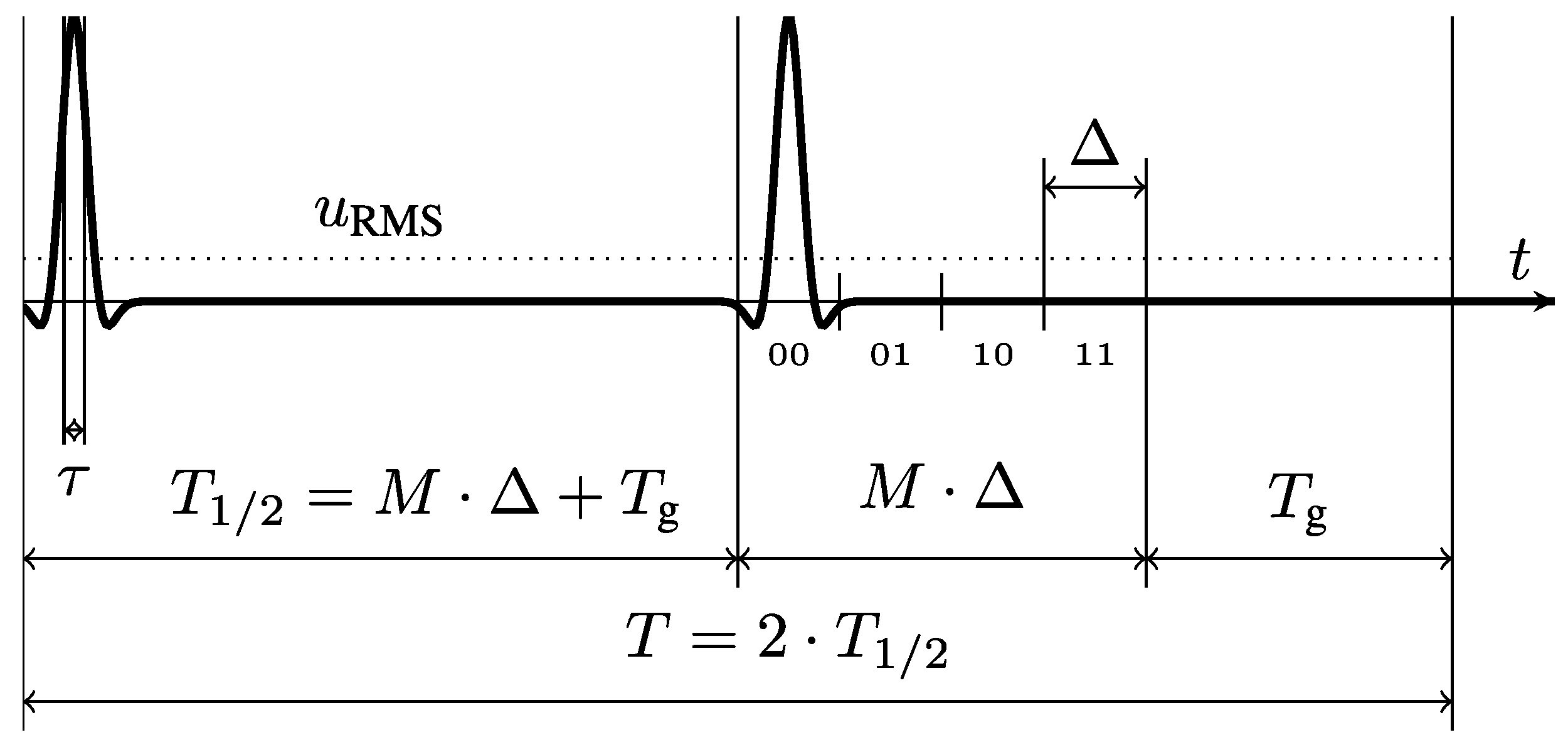
2. The Use of PPM
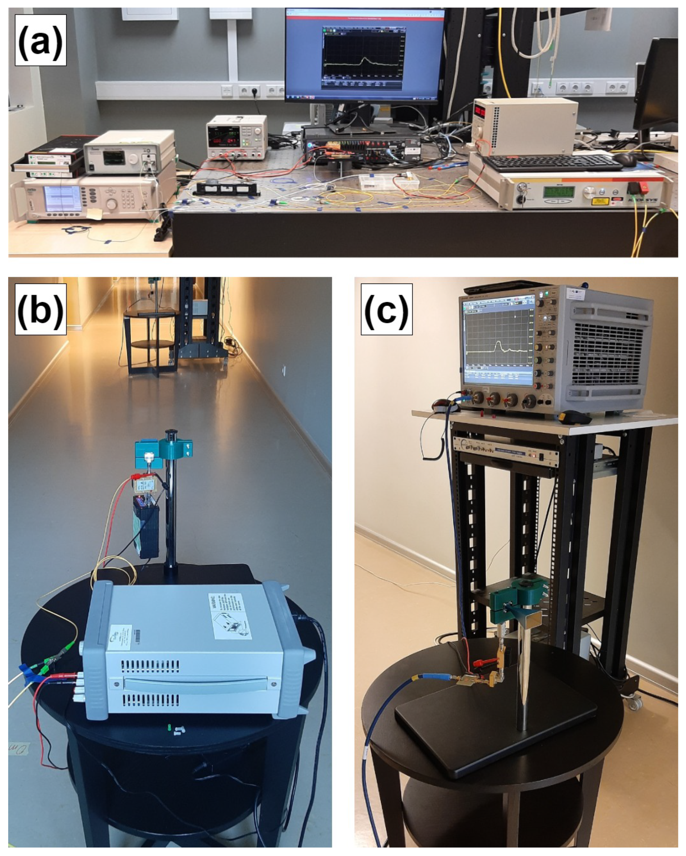
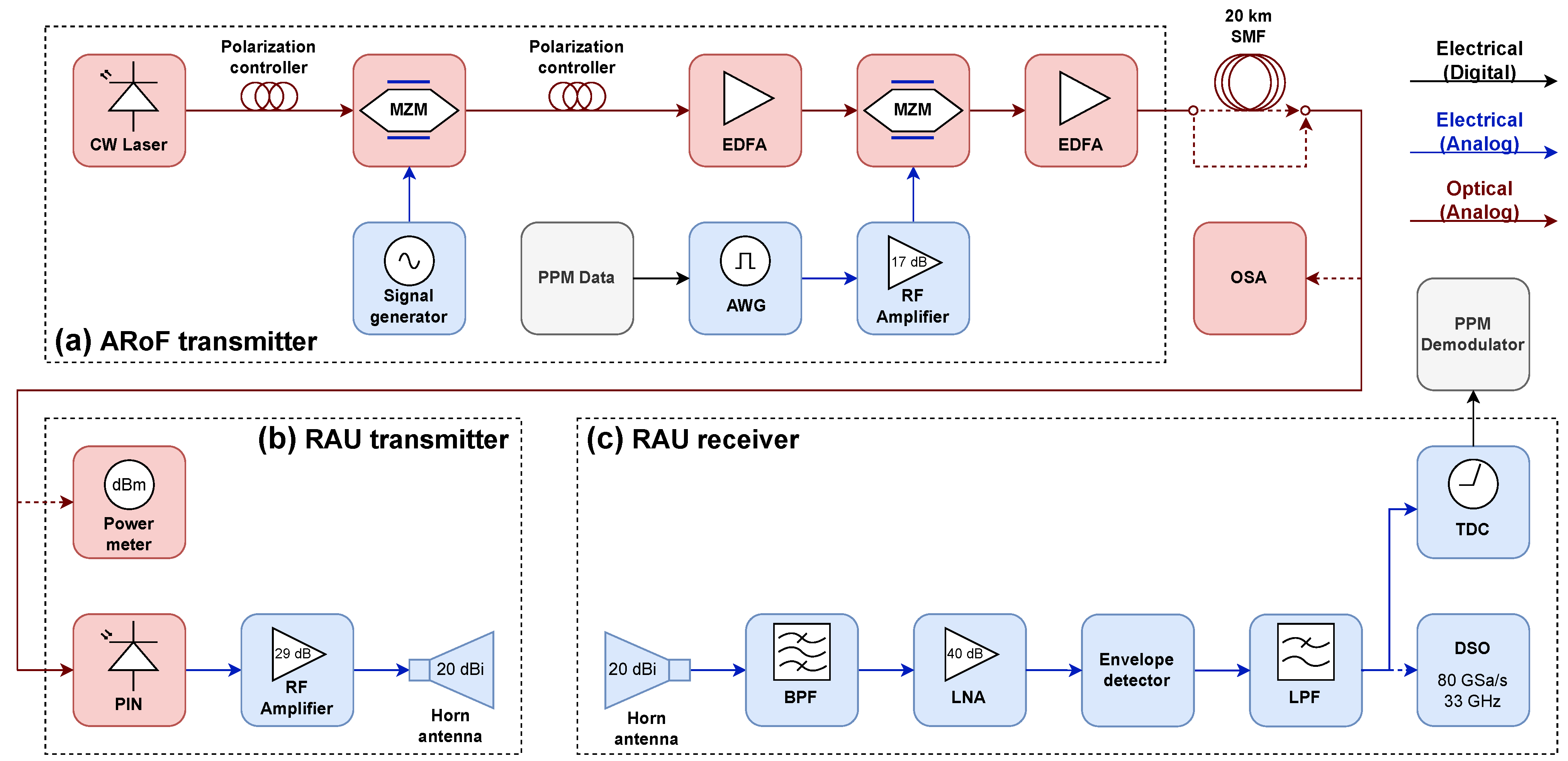
3. Experimental Setup
3.1. ARoF Transmitter
3.2. RAU Transmitter
3.3. RAU Receiver
3.4. Data Preparation
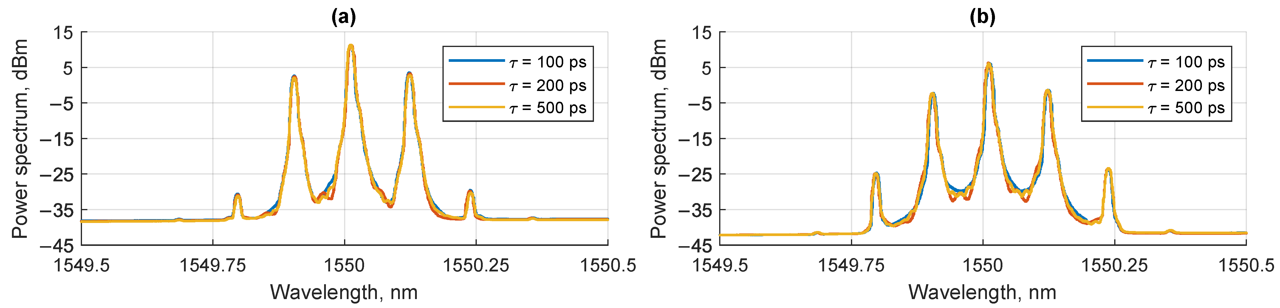
4. Experimental Results
5. Conclusions
Supplementary Materials
Author Contributions
Funding
Institutional Review Board Statement
Informed Consent Statement
Data Availability Statement
Conflicts of Interest
Abbreviations
| ADC | analog-to-digital converter |
| ARoF | analog radio-over-fiber |
| AU | antenna unit |
| AWG | arbitrary waveform generator |
| BER | bit error ratio |
| BPF | bandpass filter |
| CCSDS | Consultative Committee for Space Data Systems |
| CW | continuous wave |
| DAC | digital-to-analog converter |
| D-MIMO | distributed multiple-input multiple-output |
| DSO | digital storage oscilloscope |
| ECC | error correcting code |
| EDFA | erbium-doped fiber amplifier |
| ESRTM | Eventech Space Ready Timing Module |
| ESTT | Eventech Stream Time Tagger |
| FEC | forward error correction |
| FSO | free-space optical communication |
| FWM | four-wave mixing |
| IR-UWB | impulse radio ultra-wideband |
| ISAC | integrated sensing and communications |
| LNA | low-noise amplifier |
| LPF | low-pass filter |
| MZM | Mach-Zehnder modulator |
| NOE | nonlinear optical effects |
| OOK | on-off keying |
| PIN | p-i-n photodiode |
| PPM | pulse position modulation |
| PRBS | pseudorandom binary sequence |
| QAM | quadrature amplitude modulation |
| QSSB-UWB | quasi single-sideband UWB |
| RAU | remote antenna unit |
| RF | radio frequency |
| RMS | root mean square |
| RoF | radio-over-fiber |
| RS | Reed-Solomon |
| SMF | single-mode optical fiber |
| TDC | time-to-digital converter |
| TR-PPM | transmitted reference PPM |
| UWB | ultra-wideband |
References
- ITU-R. Report ITU-R M.2516-0: Future Technology Trends of Terrestrial International Mobile Telecommunications Systems Towards 2030 and Beyond; ITU-R: Geneva, Switzerland, 2022. [Google Scholar]
- Wikström, G.; Peisa, J.; Rugeland, P.; Johansson, N.; Parkvall, S.; Girnyk, M.; Mildh, G.; Da Silva, I.L. Challenges and Technologies for 6G. In Proceedings of the 2020 2nd 6G Wireless Summit (6G SUMMIT), Levi, Finland, 17–20 March 2020; pp. 1–5. [Google Scholar] [CrossRef]
- Lim, C.; Tian, Y.; Ranaweera, C.; Nirmalathas, T.A.; Wong, E.; Lee, K.L. Evolution of Radio-Over-Fiber Technology. J. Light. Technol. 2019, 37, 1647–1656. [Google Scholar] [CrossRef]
- Puerta, R.; Jiang, T.; Joharifar, M.; Ostrovskis, A.; Salgals, T.; Rubuls, K.; Schatz, R.; Djupsjöbacka, A.; Pittalà, F.; Gruen, M.; et al. Analog Mobile Fronthaul for 6G and Beyond. J. Light. Technol. 2024, 42, 7458–7467. [Google Scholar] [CrossRef]
- Ostrovskis, A.; Salgals, T.; Rubuls, K.; Skladova, L.; Bobrovs, V.; Spolitis, S. Experimental Demonstration of Hybrid Photonics-BasedARoF System for 5G and B5G Networks. In Proceedings of the 2022 International Conference on Software, Telecommunications and Computer Networks (SoftCOM), Split, Croatia, 22–24 September 2022; pp. 1–5. [Google Scholar] [CrossRef]
- Jiang, W.; Schotten, H.D. Full-Spectrum Wireless Communications for 6G and Beyond: From Microwave, Millimeter-Wave, Terahertz to Lightwave. In Proceedings of the 2023 IEEE 3rd International Conference on Computer Communication and Artificial Intelligence (CCAI), Taiyuan, China, 26–28 May 2023; pp. 353–357. [Google Scholar] [CrossRef]
- Li, W.; Yu, J.; Ji, X.; Liu, J.; Wang, F.; Zhu, B.; Zhou, W.; Zhao, F.; Yu, J. Over 100 Gb/s mm-wave delivery with 4600 m wireless distance based on dual polarization multiplexing. Sci. China Inf. Sci. 2023, 66, 1869–1919. [Google Scholar] [CrossRef]
- Jia, S.; Lo, M.C.; Zhang, L.; Ozolins, O.; Udalcovs, A.; Kong, D.; Pang, X.; Guzman, R.; Yu, X.; Xiao, S.; et al. Integrated Dual-Laser Photonic Chip for High-Purity Carrier Generation Enabling Ultrafast Terahertz Wireless Communications. Nat. Commun. 2022, 13, 1388. [Google Scholar] [CrossRef] [PubMed]
- Jiang, T.; Rubuls, K.; Joharifar, M.; Ostrovskis, A.; Djupsjöbacka, A.; Salgals, T.; Zvěřina, J.; Halmo, L.; Spolitis, S.; Bobrovs, V.; et al. Photonics-Enabled 6G Distributed MIMO: Experimental Study in an Indoor Environment. In Proceedings of the 2024 International Topical Meeting on Microwave Photonics (MWP), Pisa, Italy, 17–20 September 2024; pp. 1–5. [Google Scholar] [CrossRef]
- Yao, J. Microwave Photonics. J. Light. Technol. 2009, 27, 314–335. [Google Scholar] [CrossRef]
- Anes, B.; Riad, B.A. A new bidirectional analog radio over fiber transmission for 5G millimeter wave communication systems. In Proceedings of the 2022 International Conference of Advanced Technology in Electronic and Electrical Engineering (ICATEEE), M’sila, Algeria, 26–27 November 2022; pp. 1–6. [Google Scholar] [CrossRef]
- Perez-Galacho, D.; Sartiano, D.; Sales, S. Analog Radio over Fiber Links for Future 5G Radio Access Networks. In Proceedings of the 2019 21st International Conference on Transparent Optical Networks (ICTON), Angers, France, 9–13 July 2019; pp. 1–4. [Google Scholar] [CrossRef]
- Delmade, A.; Vargas, C.; Kearney, A.; Nellen, S.; Kohlhaas, R.B.; Schell, M.; Coffey, D.; Smyth, F.; Barry, L.P. Expanded Gain-Switched Comb Source for 180–260 GHz Sub-THz Analog Radio-over-Fiber 6G Wireless System. In Proceedings of the 2024 Optical Fiber Communications Conference and Exhibition (OFC), San Diego, CA, USA, 24–28 March 2024; pp. 1–3. [Google Scholar]
- de Souza Lopes, C.H.; Saia Lima, E.; Sodré Junior, A.C. RoF/FSO-based Fronthaul for 5G Systems and Beyond. In Proceedings of the 2021 SBMO/IEEE MTT-S International Microwave and Optoelectronics Conference (IMOC), Fortaleza, Brazil, 24–27 October 2021; pp. 1–3. [Google Scholar] [CrossRef]
- Nguyen, D.N.; Bohata, J.; Komanec, M.; Zvanovec, S.; Ortega, B.; Ghassemlooy, Z. Optical Hybrid Fiber/Free-Space and 25 GHz Wireless Transmission Using LTE M-QAM Signals. In Proceedings of the 2019 22nd International Symposium on Wireless Personal Multimedia Communications (WPMC), Lisbon, Portugal, 24–27 November 2019; pp. 1–6. [Google Scholar] [CrossRef]
- Azizpour, R.; Zakeri, H.; Moradi, G.; Alibakhshikenari, M.; Falcone, F.; Liu, B.; Dendini, T.A.; Park, I.; Koziel, S.; Limiti, E. Multi-Channel Radio-Over-Fiber Communication Systems Through Modulation Instability Phenomenon. IEEE Photonics J. 2024, 16, 7201813. [Google Scholar] [CrossRef]
- Jia, Z.; Yu, J.; Chang, G.K. A Full-Duplex Radio-over-Fiber System Based on Optical Carrier Suppression and Reuse. IEEE Photonics Technol. Lett. 2006, 18, 1726–1728. [Google Scholar] [CrossRef]
- Yang, L.; Giannakis, G. Ultra-wideband communications: An idea whose time has come. IEEE Signal Process. Mag. 2004, 21, 26–54. [Google Scholar] [CrossRef]
- Al Zaman, A.; Islam, N. Modulation Schemes and Pulse Shaping in Ultra-Wideband. In Proceedings of the IEEE SoutheastCon 2008, Huntsville, AL, USA, 3–6 April 2008; pp. 142–146. [Google Scholar] [CrossRef]
- Huo, X.; Xiang, M.; Zhou, G.; Li, J.; Li, J.; Qin, Y.; Fu, S. C-Band 200 Gbit/s/λ PS-PAM-8 Transmission Over 2-km SSMF for Optical Interconnections. IEEE Photonics J. 2024, 16, 7200807. [Google Scholar] [CrossRef]
- Pan, S.; Yao, J. UWB-Over-Fiber Communications: Modulation and Transmission. J. Light. Technol. 2010, 28, 2445–2455. [Google Scholar] [CrossRef]
- Pan, S.; Yao, J. Performance evaluation of UWB signal transmission over optical fiber. IEEE J. Sel. Areas Commun. 2010, 28, 889–900. [Google Scholar] [CrossRef]
- Abraha, S.T.; Okonkwo, C.; Yang, H.; Visani, D.; Shi, Y.; Jung, H.D.; Tangdiongga, E.; Koonen, T. Performance Evaluation of IR-UWB in Short-Range Fiber Communication Using Linear Combination of Monocycles. J. Light. Technol. 2011, 29, 1143–1151. [Google Scholar] [CrossRef]
- Kaszubowska-Anandarajah, A.; Perry, P.; Barry, L.P.; Shams, H. An IR-UWB Photonic Distribution System. IEEE Photonics Technol. Lett. 2008, 20, 1884–1886. [Google Scholar] [CrossRef]
- Fujiwara, Y. Self-Synchronizing Pulse Position Modulation With Error Tolerance. IEEE Trans. Inf. Theory 2013, 59, 5352–5362. [Google Scholar] [CrossRef]
- Mahdiraji, G.A.; Zahedi, E. Comparison of Selected Digital Modulation Schemes (OOK, PPM and DPIM) for Wireless Optical Communications. In Proceedings of the 2006 4th Student Conference on Research and Development, Shah Alam, Malaysia, 27–28 June 2006; pp. 5–10. [Google Scholar] [CrossRef]
- Li, L.; Townsend, J.K. M-Ary PPM for Transmitted Reference Ultra-Wideband Communications. IEEE Trans. Commun. 2010, 58, 1912–1917. [Google Scholar] [CrossRef]
- Luo, X.; Giannakis, G. Achievable Rates of Transmitted-Reference Ultra-Wideband Radio with PPM. IEEE Trans. Commun. 2006, 54, 1536–1541. [Google Scholar] [CrossRef]
- Aliaberi, A.; Sofotasios, P.C.; Muhaidat, S. Modulation Schemes for Visible Light Communications. In Proceedings of the 2019 International Conference on Advanced Communication Technologies and Networking (CommNet), Rabat, Morocco, 12–14 April 2019; pp. 1–10. [Google Scholar] [CrossRef]
- Dahri, F.A.; Ali, S.; Jawaid, M.M. A Review of Modulation Schemes for Visible Light Communication. IJCSNS Int. J. Comput. Sci. Netw. Secur. 2018, 18, 117–125. [Google Scholar]
- Mietzner, J.; Lampe, L. Nested PPM for Visible Light Communication with Heterogeneous Optical Receivers. IEEE Photonics J. 2024, 16, 7302112. [Google Scholar] [CrossRef]
- Alabd, M.B.; Nuss, B.; de Oliveira, L.G.; Diewald, A.; Li, Y.; Zwick, T. Modified Pulse Position Modulation for Joint Radar Communication Based on Chirp Sequence. IEEE Microw. Wirel. Compon. Lett. 2022, 32, 1247–1250. [Google Scholar] [CrossRef]
- Guelman, M.; Kogan, A.; Kazarian, A.; Livne, A.; Orenstein, M.; Michalik, H. Acquisition and Pointing Control for Inter-Satellite Laser Communications. IEEE Trans. Aerosp. Electron. Syst. 2004, 40, 1239–1248. [Google Scholar] [CrossRef]
- Colson, S.; Hoff, H. Ultra-Wideband Technology for Defence Applications. In Proceedings of the 2005 IEEE International Conference on Ultra-Wideband, Zurich, Switzerland, 5–8 September 2005; pp. 615–620. [Google Scholar] [CrossRef]
- Eventech. Key Products. Available online: https://eventechsite.com/products/ (accessed on 27 March 2025).
- Selis, O.; Migla, S.; Sics, P.E.; Zeltins, M.; Spolitis, S.; Aboltins, A. Demonstration of 50 ps Per-Position Differential Pulse Position Modulation Data Transmission. In Proceedings of the 2023 IEEE 10th Jubilee Workshop on Advances in Information, Electronic and Electrical Engineering (AIEEE), Vilnius, Lithuania, 27–29 April 2023; pp. 1–4. [Google Scholar] [CrossRef]
- Sics, P.E.; Tihomorskis, N.; Migla, S.; Ratners, J.; Kurtenoks, V.; Aboltins, A. Implementation of Reconfigurable 149 Mbps TDC-Based PPM Transceiver. In Proceedings of the 2024 Joint European Conference on Networks and Communications & 6G Summit (EuCNC/6G Summit), Antwerp, Belgium, 3–6 June 2024; pp. 706–710. [Google Scholar] [CrossRef]
- Eventech. Eventech Space Ready Timing Module. Available online: https://eventechsite.com/wp-content/uploads/2024/08/Eventech-Space-Ready-Timing-Module-2024.pdf (accessed on 27 March 2025).
- European Space Agency. Hera’s Asteroid Deck and instruments. Available online: https://www.esa.int/Space_Safety/Hera/Hera_s_Asteroid_Deck_and_instruments (accessed on 27 March 2025).
- Aboltins, A.; Solovjova, T.; Semenako, J.; Kusnins, R.; Migla, S.; Sics, P.E.; Selis, O.; Tihomorskis, N.; Prigunovs, D.; Ostrovskis, A.; et al. Passive Electrical and Optical Methods of Ultra-Short Pulse Expansion for Event Timer-Based TDC in PPM Receiver. Electronics 2023, 12, 4634. [Google Scholar] [CrossRef]
- Liu, Y.; Wang, C. The Research on Transmission Effect of Different Pulse Shapes in MPPM. In Proceedings of the 2022 14th International Conference on Computer Research and Development (ICCRD), Shenzhen, China, 7–9 January 2022; pp. 373–377. [Google Scholar] [CrossRef]
- Cho, S.; Kwak, J. Performance Comparison of M-Ary PPM Ultra-Wideband Multiple Access System Using an Intelligent Pulse Shaping Techniques. In International Conference on Knowledge-Based and Intelligent Information and Engineering Systems; Springer: Berlin/Heidelberg, Germany, 2005; pp. 1094–1103. [Google Scholar]


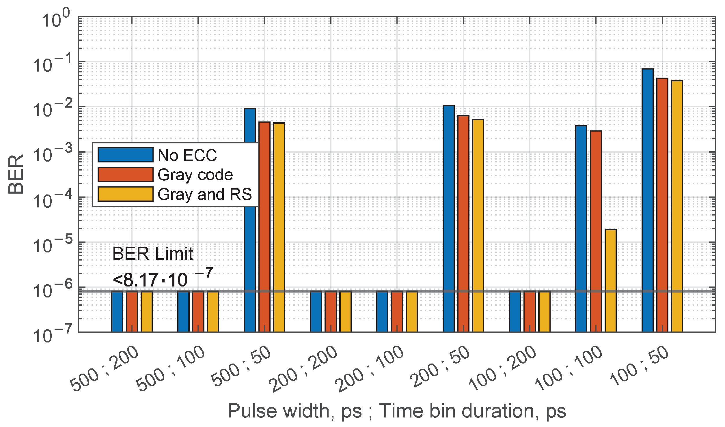
| ECC | Pulse Duration , ps | Time Bin Duration , ps | Number of Positions M | 20 km Fiber BER | Back-to-Back BER |
|---|---|---|---|---|---|
| No ECC | 500 | 200 | 128 | <8.17 × 10⁻⁷ | <8.17 × 10⁻⁷ |
| 500 | 100 | 256 | <8.17 × 10⁻⁷ | <8.17 × 10⁻⁷ | |
| 500 | 50 | 512 | 2.578 × 10⁻² | 9.169 × 10⁻³ | |
| 200 | 200 | 128 | <8.17 × 10⁻⁷ | <8.17 × 10⁻⁷ | |
| 200 | 100 | 256 | <8.17 × 10⁻⁷ | <8.17 × 10⁻⁷ | |
| 200 | 50 | 512 | 3.848 × 10⁻² | 1.068 × 10⁻² | |
| 100 | 200 | 128 | <8.17 × 10⁻⁷ | <8.17 × 10⁻⁷ | |
| 100 | 100 | 256 | 5.936 × 10⁻³ | 3.781 × 10⁻³ | |
| 100 | 50 | 512 | 7.436 × 10⁻² | 6.931 × 10⁻² | |
| Gray code | 500 | 200 | 128 | <8.17 × 10⁻⁷ | <8.17 × 10⁻⁷ |
| 500 | 100 | 256 | <8.17 × 10⁻⁷ | <8.17 × 10⁻⁷ | |
| 500 | 50 | 512 | 9.433 × 10⁻³ | 4.572 × 10⁻³ | |
| 200 | 200 | 128 | <8.17 × 10⁻⁷ | <8.17 × 10⁻⁷ | |
| 200 | 100 | 256 | <8.17 × 10⁻⁷ | <8.17 × 10⁻⁷ | |
| 200 | 50 | 512 | 2.518 × 10⁻² | 6.317 × 10⁻³ | |
| 100 | 200 | 128 | <8.17 × 10⁻⁷ | <8.17 × 10⁻⁷ | |
| 100 | 100 | 256 | 3.524 × 10⁻³ | 2.924 × 10⁻³ | |
| 100 | 50 | 512 | 4.427 × 10⁻² | 4.318 × 10⁻² | |
| Gray code and RS | 500 | 200 | 256 | <8.17 × 10⁻⁷ | <8.17 × 10⁻⁷ |
| 500 | 100 | <8.17 × 10⁻⁷ | <8.17 × 10⁻⁷ | ||
| 500 | 50 | 9.285 × 10⁻³ | 4.356 × 10⁻³ | ||
| 200 | 200 | <8.17 × 10⁻⁷ | <8.17 × 10⁻⁷ | ||
| 200 | 100 | <8.17 × 10⁻⁷ | <8.17 × 10⁻⁷ | ||
| 200 | 50 | 1.584 × 10⁻² | 5.267 × 10⁻³ | ||
| 100 | 200 | <8.17 × 10⁻⁷ | <8.17 × 10⁻⁷ | ||
| 100 | 100 | 1.514 × 10⁻⁴ | 1.875 × 10⁻⁵ | ||
| 100 | 50 | 4.226 × 10⁻² | 3.804 × 10⁻² |
Disclaimer/Publisher’s Note: The statements, opinions and data contained in all publications are solely those of the individual author(s) and contributor(s) and not of MDPI and/or the editor(s). MDPI and/or the editor(s) disclaim responsibility for any injury to people or property resulting from any ideas, methods, instructions or products referred to in the content. |
© 2025 by the authors. Licensee MDPI, Basel, Switzerland. This article is an open access article distributed under the terms and conditions of the Creative Commons Attribution (CC BY) license (https://creativecommons.org/licenses/by/4.0/).
Share and Cite
Migla, S.; Rubuls, K.; Tihomorskis, N.; Salgals, T.; Ozolins, O.; Bobrovs, V.; Spolitis, S.; Aboltins, A. Ultra-Wideband Analog Radio-over-Fiber Communication System Employing Pulse-Position Modulation. Appl. Sci. 2025, 15, 4222. https://doi.org/10.3390/app15084222
Migla S, Rubuls K, Tihomorskis N, Salgals T, Ozolins O, Bobrovs V, Spolitis S, Aboltins A. Ultra-Wideband Analog Radio-over-Fiber Communication System Employing Pulse-Position Modulation. Applied Sciences. 2025; 15(8):4222. https://doi.org/10.3390/app15084222
Chicago/Turabian StyleMigla, Sandis, Kristaps Rubuls, Nikolajs Tihomorskis, Toms Salgals, Oskars Ozolins, Vjaceslavs Bobrovs, Sandis Spolitis, and Arturs Aboltins. 2025. "Ultra-Wideband Analog Radio-over-Fiber Communication System Employing Pulse-Position Modulation" Applied Sciences 15, no. 8: 4222. https://doi.org/10.3390/app15084222
APA StyleMigla, S., Rubuls, K., Tihomorskis, N., Salgals, T., Ozolins, O., Bobrovs, V., Spolitis, S., & Aboltins, A. (2025). Ultra-Wideband Analog Radio-over-Fiber Communication System Employing Pulse-Position Modulation. Applied Sciences, 15(8), 4222. https://doi.org/10.3390/app15084222