Article

Dual-Indicator Micro-Electro-Mechanical System Monitoring Method for Rock Instability Early Warning

1
School of Resources and Safety Engineering, University of Science and Technology Beijing, Beijing 100083, China
2
School of Future Cities, University of Science and Technology Beijing, Beijing 100083, China
3
Beijing Water Science and Technology Institute, Beijing 100048, China
*
Author to whom correspondence should be addressed.
Appl. Sci. 2025, 15(8), 4210; https://doi.org/10.3390/app15084210
Submission received: 12 February 2025 / Revised: 22 March 2025 / Accepted: 25 March 2025 / Published: 11 April 2025
(This article belongs to the Topic Geotechnics for Hazard Mitigation)

Abstract

:
Traditional displacement monitoring struggles to provide early warnings for sudden rock collapses. This study proposes a Micro-Electro-Mechanical System (MEMS) sensor-based monitoring method using dual dynamic indicators. By analyzing sensor mechanisms through vibration dynamics theory and establishing theoretical models via moment equilibrium equations, we derived a quantitative correlation between natural frequency (NF) and safety factor, identifying a 4:3 scaling coefficient specific to toppling-type unstable rocks. An innovative stability criterion algorithm integrating NF and the root mean square velocity amplitude ratio (RMS-VAR) was developed, revealing that RMS-VAR detects stability degradation three times faster than tilt measurements. Laboratory tests confirmed MEMS sensors’ reliability in monitoring NF, amplitude ratio, and tilt angles, demonstrating that sensor deployment strategies and rock geometry jointly determine model accuracy. This quantitative approach offers a novel solution for monitoring sudden geological hazards, combining timeliness with cost-effectiveness.

1. Introduction

As a major energy-producing country, China has gained significant economic benefits from the development of cascade power stations and mining operations. Nevertheless, geohazards, including slope collapse disasters, continue to impose substantial socioeconomic impacts [1]. Due to complex geological conditions, frequent seismic activities, and engineering construction disturbances, rock mass internal stress imbalance frequently leads to collapse accidents [2]. The prevention of unstable rock mass collapse poses a major challenge in engineering geological disaster mitigation, given its sudden occurrence and spatially dispersed nature. Consequently, real-time stability monitoring and the early warning of collapsing unstable rock masses remain critical practical issues in geotechnical engineering.
For rock masses or blocks exhibiting potential instability on natural slopes, the deterioration of their primary structural planes plays a decisive role in stability control. Experimental validations and practical applications have demonstrated the effectiveness of monitoring methods utilizing vibration characteristics to assess structural plane degradation. The NF of an unstable rock mass, as its intrinsic dynamic parameter, is uniquely determined by the mass matrix and stiffness matrix. Iannucci et al. [3] employed passive seismic techniques to analyze the quantitative relationship between the NF and the stability of toppling rock masses. Bottelin et al. [4] employed ambient vibration response to verify stability variations in rock mass reinforcement effectiveness. Mercerat et al. [5] conducted a dynamic characteristic analysis of coastal slopes using ambient vibration, delineating deep structural features that were superficially undetectable. Additional studies have explored unstable rock mass vibration responses through vibration mechanics and dynamic mathematical analyses [6]. Chen Hongkai et al. [7] employed dynamics theory to analyze energy transitions during rock mass sliding, establishing theoretical formulas for elastic–impact velocity and acceleration. Internationally, seismic monitoring equipment has been predominantly employed for large unstable rock mass vibration studies [8]. Burjánek et al. [9] identified directional amplification effects correlated with structural plane orientation and slope deformation through environmental vibration data analysis. Glueer et al. [10] utilized passive seismic measurements to map subsurface structural plane distributions (30–90 m depth). Hausler et al. [11,12] performed modal analyses using 1 h environmental vibration datasets, enabling the spatial mapping of undetectable subsurface fractures via frequency-dependent vibration pattern correlations. Iannucci et al. [3] observed linear polarization in unstable rock mass particle trajectories through spectral ratio comparisons with the parent rock. These investigations confirm that vibration-derived dynamic indicators offer innovative approaches for collapse monitoring. However, traditional seismic equipment and single-index methodologies prove inadequate for ensuring monitoring accuracy and early-warning reliability. MEMS sensing, as a miniaturized technology integrating micro-mechanical structures, sensors, actuators, and electronic circuits, provides a reliable method for monitoring data acquisition in unstable rock masses. Compared to conventional vibration sensing, MEMS technology provides distinct advantages including miniaturization, low cost, low power consumption, and wide frequency response—essential features for complex engineering scenarios. Wu Di et al. [13] utilized MEMS sensors to conduct monitoring verification on highway slope displacement. Praveen et al. [14] implemented a real-time monitoring methodology for low-speed machinery using IoT technology and MEMS sensors. The convergence of MEMS sensing with wireless transmission and big data analytics has emerged as a novel research frontier in geotechnical disaster monitoring, though applications specifically targeting unstable rock mass collapse remain limited.
Unstable rock mass collapse prediction constitutes a multivariate challenge influenced by numerous factors [15,16,17], compounded by harsh environmental conditions including construction disturbances, blasting activities, poor network connectivity, and power supply limitations [18]. In order to achieve the early warning of unstable rock mass collapse and solve the problem of the real-time evaluation of unstable rock mass stability, this study investigates MEMS sensor operational principles, establishes vibration mechanics-based quantitative relationships between NF/RMS-VAR and rock stability, and proposes a dual dynamic index algorithm. Furthermore, we discuss real-time stability evaluation models and critical implementation considerations for MEMS-based monitoring methods. The developed MEMS sensing methodology provides enhanced temporal warning capabilities and novel non-engineering control strategies for preventing sudden geotechnical disasters.

2. Fundamental Theory and Methodology

2.1. MEMS Sensing Mechanisms

The stability of unstable rock masses gradually decreases with the deterioration of their main structural planes [19]. Under normal fretting conditions, the vibration characteristics of unstable rock masses differ from those of the bedrock to some extent, and these differences become more pronounced with increasing degrees of structural deterioration. MEMS sensing provides a novel technology for monitoring unstable rock mass collapse, owing to its high sensitivity, low power consumption, and compact dimensions. As shown in Figure 1a, vibration signals can be acquired by affixing MEMS sensors to the unstable rock mass and bedrock using gypsum bonding or bolting methods, combined with wired or wireless transmission systems. Figure 1b schematically represents the MEMS sensor as a cubic enclosure containing a miniature metallic sphere. When subjected to gravitational forces and micro-vibrations from unstable rock masses, this sphere undergoes inertial displacement, thereby inducing electrical signals of varying magnitudes through wall impacts. The system ultimately outputs triaxial acceleration, velocity, and displacement measurements.
MEMS sensors acquire vibration data from rock masses through direct contact measurements. As illustrated in Equation (1), a conventional MEMS accelerometer continuously measures triaxial acceleration components, including gravitational acceleration, through its embedded micro-electro-mechanical structures.
a ( t ) = F ( t ) m a ( t ) = a x 2 ( t ) + a y 2 ( t ) + a z 2 ( t )
where F ( t ) represents the impact force acting on a rock mass of mass m. a ( t ) represents the triaxial acceleration measured by MEMS sensors, a ( t ) = ( a x ( t ) , a y ( t ) , a z ( t ) ) .

2.2. Dynamic Interdependence: NF Versus Safety Factor

According to vibration mechanics theory, unstable rock masses exhibit characteristic vibration under external excitation, which inherently reflect their mechanical properties [20]. To establish quantitative correlations between rock mass stability and vibrational signatures, we systematically analyzed dominant stability control factors through mechanical characterization. Figure 2 illustrates the force equilibrium of typical toppling-prone rock masses, where two critical moments coexist: (1) toppling moment induced by gravitational forces; (2) resisting moment is generated through structural plane bonding.
Where l denotes the bonding length of the principal structural plane. When l decreases below critical thresholds, the resisting moment becomes insufficient to counteract gravitational toppling forces, ultimately triggering collapse. The instability failure characteristics of this unstable rock mass are primarily manifested as a rotational failure mode around a specific pivot point, caused by unbalanced moments resulting from either load increase or cohesion decrease. This demonstrates that structural plane bonding length constitutes the pivotal control parameter for rock mass stability. According to limit equilibrium principles, the safety factor K for toppling-prone rock mass is defined as the ratio of the resisting moment to the toppling moment, as expressed in Equation (2):
K = ( F × l / 2 ) G × e = δ s T l 2 s 2 G e
where F is the resisting force; e is the distance between the center of gravity of rock mass and the structural plane; δ s is the tensile strength of rock mass; T is the thickness of rock mass; and s is the width of rock mass. G represents the gravitational force of the unstable rock mass.
The square of the bonding length l 2 in unstable rock mass structural planes exhibits a positive correlation with the safety factor K . When l diminishes to the critical stability threshold l c , the safety factor reaches the unity ( K = 1) [2]. Rock mass failure initiates when K < 1, indicating a loss of structural equilibrium. This early-warning methodology employs MEMS sensors to track vibrational frequency modulations that correlate with the reduction in the bonding length of the principal structural plane. The NF constitutes an intrinsic parameter of rock mass vibrational dynamics. As shown in Figure 3, the unstable rock mass can be simplified into a single-degrees-of-freedom (SDOF) spring–mass oscillator. The motion balance shown in Equation (3) is established according to Newton’s Second Law, and NF expression is shown in Equation (4) [20].
Where the stiffness decreases proportionally with bonding length reduction. This stiffness degradation induces measurable frequency attenuation, enabling the quantitative assessment of structural integrity through frequency-domain analysis.
m e β ¨ ( t ) + l 3 E T s 3 d β ( t ) = 0
f 0 = ( 1 / 2 π ) ( E T l 3 s g ) / ( 3 d G e 2 )
where β ( t ) is the change in tilt angle in the vibration process; m is the quality of unstable rock mass; and f 0 is the NF of unstable rock mass.
According to Equations (2) and (4), the mathematical expression of NF and safety factor is obtained, as shown in Equation (5):
K = 18 π 4 e T d 2 δ s f 0 4 / G E 2 g 2 3
Equation (5) established a bijective relationship between the NF of unstable rock masses and their safety. The NF of toppling-type unstable rocks exhibits a quantitative proportional relationship of 4:3 with the safety factor. Under the condition that other parameters of the rock mass remain constant, a decrease in the NF induces a monotonic decline in the safety factor. A critical NF necessarily exists at which the safety factor equals 1. Consequently, the real-time monitoring of NF variations enables instability early warning for rock masses, leveraging this deterministic frequency–safety correlation. The quantitative relationship between the NF of unstable rock mass and the safety factor can be calibrated through laboratory experiments or finite elements simulation, and the safety factor of unstable rock mass can be determined by the NF value of the field measurable index and the multi-stage early-warning threshold of unstable rock mass can be set.

2.3. Quantification Metrics for MEMS-Acquired Stability Indicators

Through MEMS sensing, the vibration time history curve of bedrock is obtained as the vibration input of the spring–mass model, and the input curve of unstable rock mass is serves as the response output. The frequency response function (FRF) H ( f ) representing the vibration response of unstable rock mass under ambient vibration can be obtained, and its calculation formula is shown in Equation (6). Under the excitation of a sinusoidal signal, the theoretical magnification factor of the spring–mass model system D ( s ) is shown in Equation (7). The NF and damping ratio of unstable rock mass can be obtained by analyzing the relationship between the theoretical amplitudes and the actual amplitudes under the multi-frequency excitation [21].
H ( f ) = P x y ( f ) P x ( f )
D ( s ) = 1 / ( 1 s 2 ) 2 + ( 2 ξ s ) 2
where P x y ( f ) is the cross-correlation power spectral density function between bedrock and unstable rock mass; P x ( f ) is the matrix autocorrelation power spectral density function; and f is the excitation frequency of the input unstable rock mass under constant fretting.
When the frequency ratio reaches the unity ( f = f 0 ), the amplification factor D ( s ) attains its maximum value. This indicates that the peak value in the actual obtained FRF is the magnification of the response amplitude caused by the resonance of the unstable rock mass, and the horizontal coordinate frequency corresponding to the peak value is the NF of the unstable rock mass.
The amplitude–amplification factor D ( s ) is the ratio of the vibration amplitude of unstable rock mass to that of bedrock under different excitation frequencies. As the NF f 0 of unstable rock mass decreases, the amplitude–amplification factor of the system under the same excitation frequency increases. Therefore, the ratio of the vibration amplitude of unstable rock mass to that of bedrock also increases. In order to reduce the error caused by the random interference of the MEMS sensor in the acquisition process of the vibration amplitude of the unstable rock mass and bedrock, the ratio of mean square velocity to the amplitude of the unstable rock mass and bedrock is adopted as the monitoring index of unstable rock mass collapse. The equation is as follows:
η = t 1 t 2 ( 1 / ( t 2 t 1 ) ) y 2 ( t ) / t 1 t 2 ( 1 / ( t 2 t 1 ) ) x 2 ( t )
where x ( t ) is the velocity time history curve of the bedrock; and y ( t ) is the velocity time history curve of unstable rock mass.
The stability state of an unstable rock mass evolves dynamically. MEMS-derived NF and RMS-VAR parameters effectively characterize the progressive destabilization of unstable rock masses. Using MEMS sensing technology, triaxial vibration time–history curves of unstable rock masses and bedrock are collected in real time, with a principal component analysis (PCA) employed to identify dominant vibration directions. Through time-domain window optimization, the FRF of unstable rock masses is calculated, and their natural frequencies are determined through fitting of amplitude amplification factors. The RMS-VAR between unstable rock masses and bedrock is derived by converting detrended acceleration curves to velocity curves. Furthermore, in engineering practice, unstable rock masses are typically formed through prolonged geological processes and often exhibit precursor phenomena such as localized rockfall events and minor deformations prior to collapse [22,23]. MEMS sensors are utilized to monitor instantaneous impact acceleration and subtle tilt angles caused by surrounding rockfalls, providing critical data support for early-warning systems of rock mass collapse.

3. Experimental Validation and Performance Evaluation

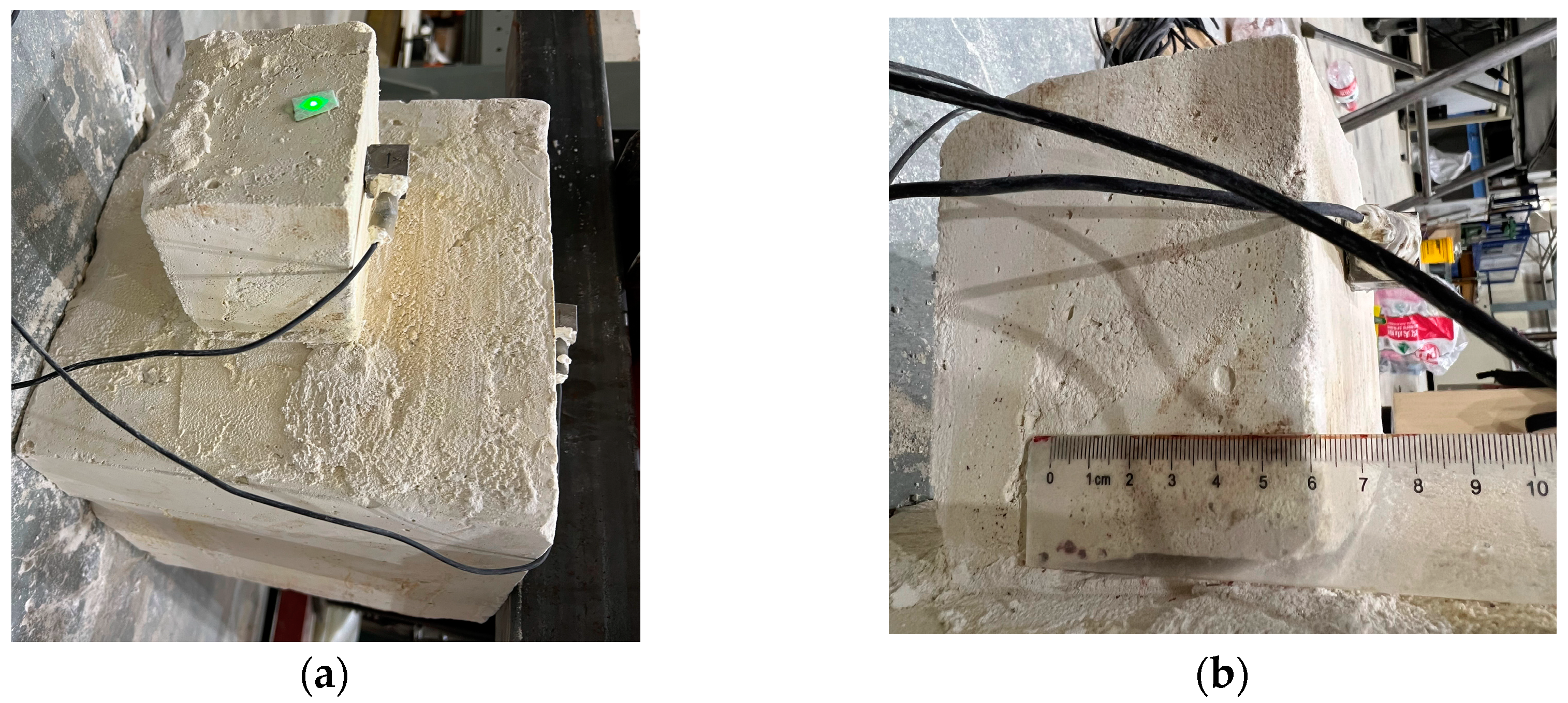
3.1. Experimental Setup and Modeling

To validate the applicability of MEMS sensing technology for unstable rock mass collapse monitoring, we developed a MEMS-based simulation monitoring system (as shown in Figure 4). The system comprises three key components: (1) artificially fabricated rock blocks with material ratios matching those of natural bedrock and parent rock formations; (2) integrated sensing instrumentation including MEMS accelerometers and a laser Doppler vibrometer (LDV) system; and (3) hydraulic stabilization jacks for bedrock anchorage.

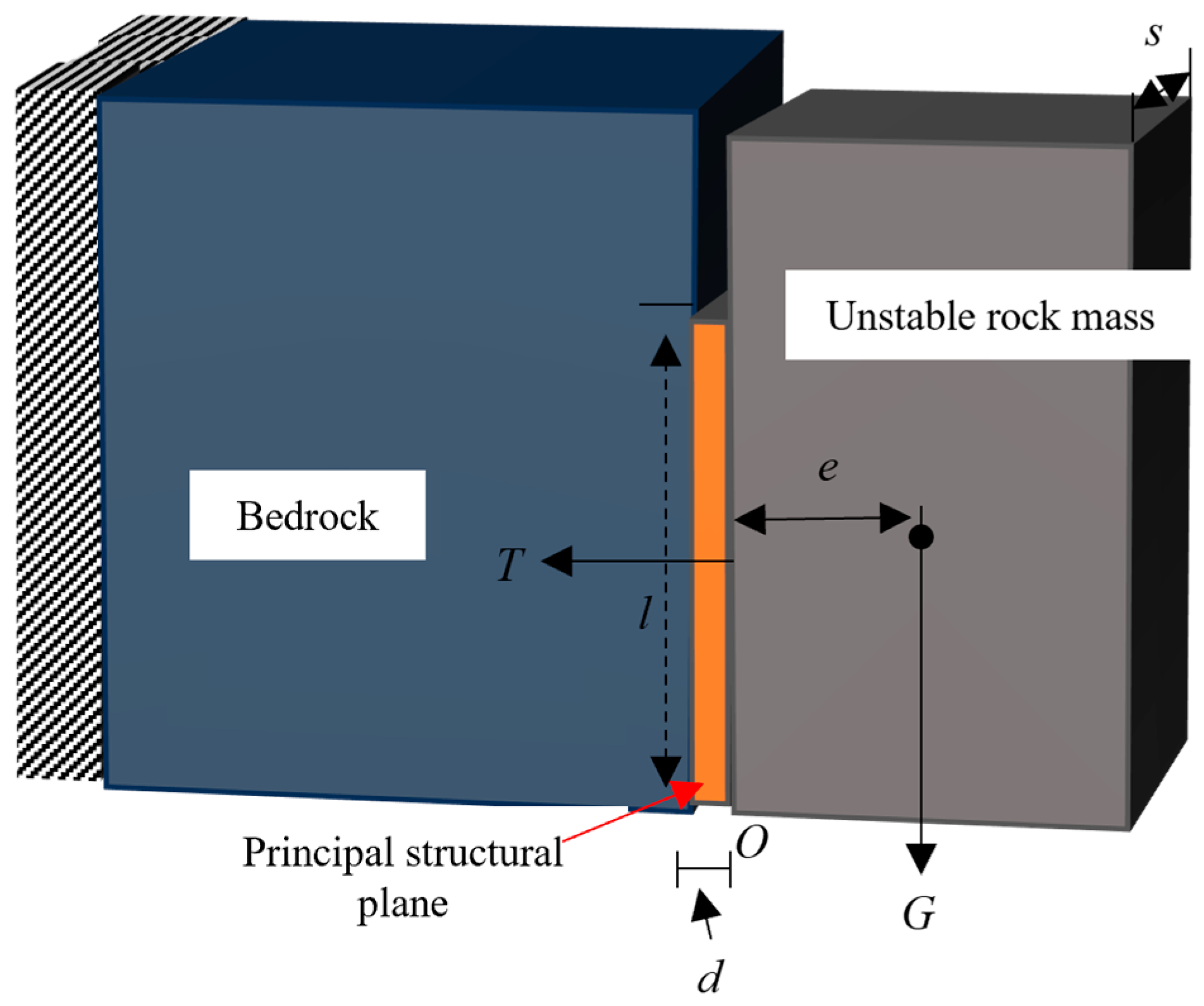
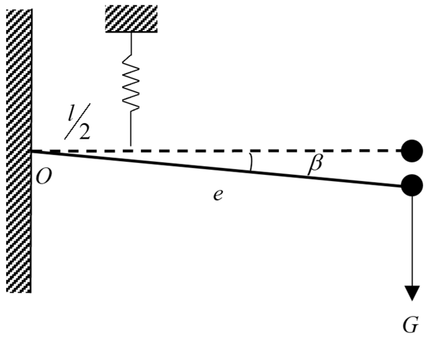
3.1.1. Rockfall Model

In this experiment, the unstable rock mass and bedrock were simulated using proportionally equivalent materials. The material composition consisted of quartz and barite powder as aggregates, gypsum as the cementitious binder, with a retarding agent and glycerol incorporated as admixtures. The optimized mass ratio for the synthetic rock matrix was formulated as: Quartz Sand:Barite Powder:Gypsum:Retarder:Water:Glycerol = 50:30:8:0.02:10:1.5. As detailed in Table 1, the fabricated specimens exhibited comparable physical properties to natural geological formations. Figure 5 illustrates the geometric configuration, where the protrusion (dimensions: 12 cm (L) × 10 cm (H) × 11.5 cm (W)) represents the unstable rock mass, while the cuboidal bedrock section (30 cm edge length) provides structural constraint. Hydraulic jacks applying 2.4 MPa vertical confinement pressure ensured bedrock stability throughout testing. The failure mechanism was systematically induced through the progressive reduction in the bonded interface area (15% increment steps) via the precision machining of the controlling structural plane.

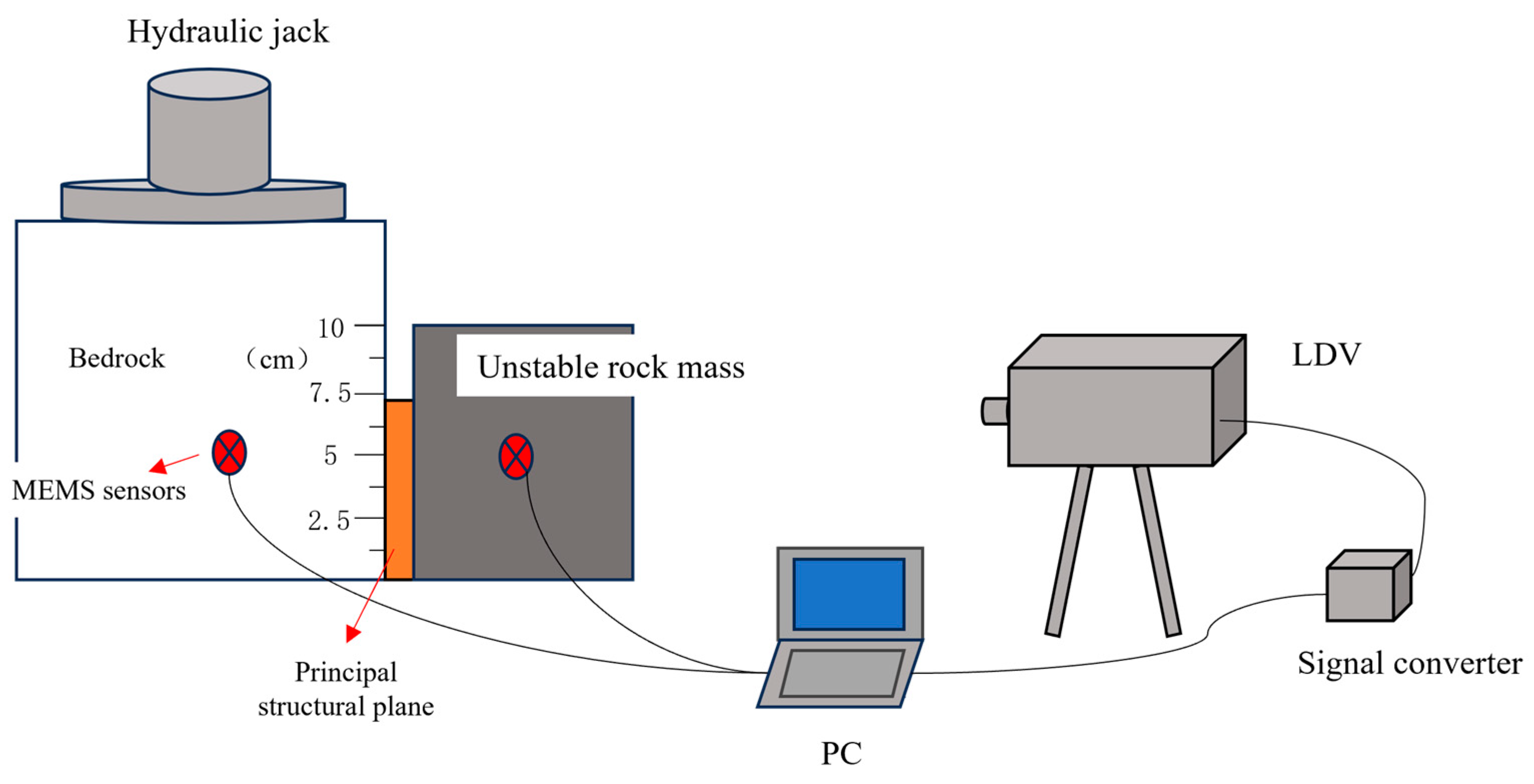
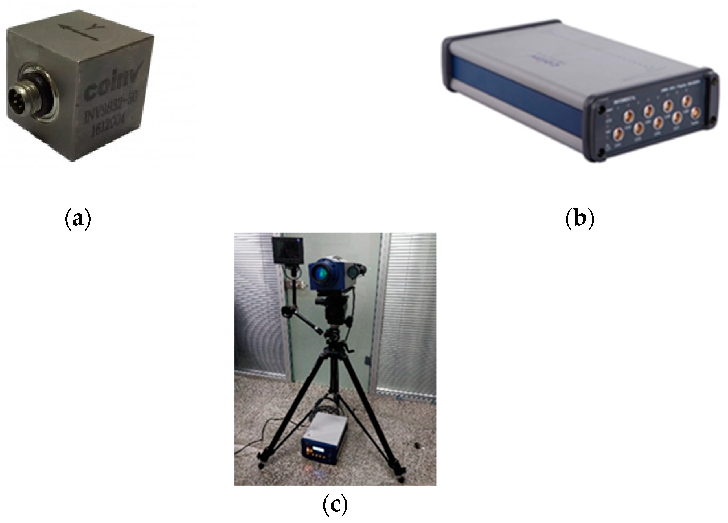
3.1.2. Data Sensing Instrumentation

As shown in Figure 6a, the triaxial MEMS acceleration sensor with built-in amplifier (model INV9832-50) developed by Dongfang Institute of Technology (Hangzhou, China) was selected for this experiment. The MEMS sensing device can monitor very small impact signals with a sensitivity of 100 mV/g, and the weight of the sensing device is about 12 g, which imposes a negligible gravitational load on the rock mass, and is suitable for acquiring the dynamics index of the rock mass. As shown in Figure 6b, the INV3062C high-precision distributed data acquisition instrument of Dongfang Institute was employed in this experiment to convert the signals collected by the MEMS sensing device, and the final data were transmitted to the computer through Ethernet cables for subsequent data analysis and processing. At the same time, as shown in Figure 6c, the accuracy of the data collected by MEMS sensing was verified by the laser vibration-measuring instrument model RSV-150 from Polytec GmbH (Waldorf, Germany). The main technical parameters of the data acquisition equipment are summarized in Table 2.

3.1.3. Dynamic Simulation of Collapse Mechanisms

The collapse process of unstable rock masses was simulated through the artificially induced cutting of the dominant structural plane. As defined in Equation (9), the relative bonding length Δ L serves as a quantitative metric for structural plane degradation. Reductions in this length correlate directly with heightened deterioration severity and diminished rock mass stability.
Δ L = 1 L L 0
where L is the cumulative length of artificially cut structural plane; and L 0 is the height of unstable rock mass, taking 10 cm.
The collapse simulation protocol involved progressive 0.5 cm depth cuts to structural planes until failure initiation. Table 3 quantifies the cutting length-to-relative bonding length correlation across 14 distinct working conditions for unstable rock masses.

3.2. Experimental Results

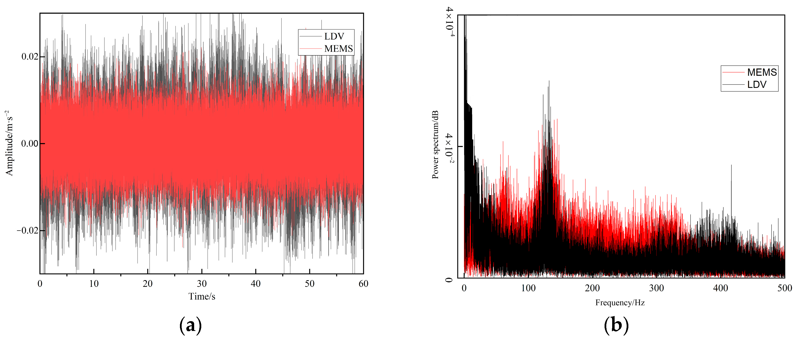
3.2.1. MEMS-Laser Vibrometry Cross-Validation

To validate the MEMS sensing’s efficacy in monitoring unstable rock mass vibrations under constant micro-motion conditions, a comparative analysis was conducted between high-precision LDV measurements and MEMS-acquired data. Both systems were aligned along identical measurement axes, with synchronized sampling at 1000 Hz over a 60 s acquisition period. Prior to analysis, sensitivity calibration and 5th-order Butterworth low-pass filtering (cutoff: 500 Hz) were applied to mitigate device-specific discrepancies.
As illustrated in Figure 7a, the MEMS sensor demonstrates amplitude fidelity to LDV measurements, exhibiting merely 3.4% standard deviation error with reduced amplitude variance. Figure 7b reveals that, while environmental vibrations introduce sub-100 Hz discrepancies in LDV data, both modalities show a strong spectral coherence in the range of 100–500 Hz. These results confirm MEMS technology’s capability to reliably capture micro-motion vibration signatures critical for rock mass stability assessment.

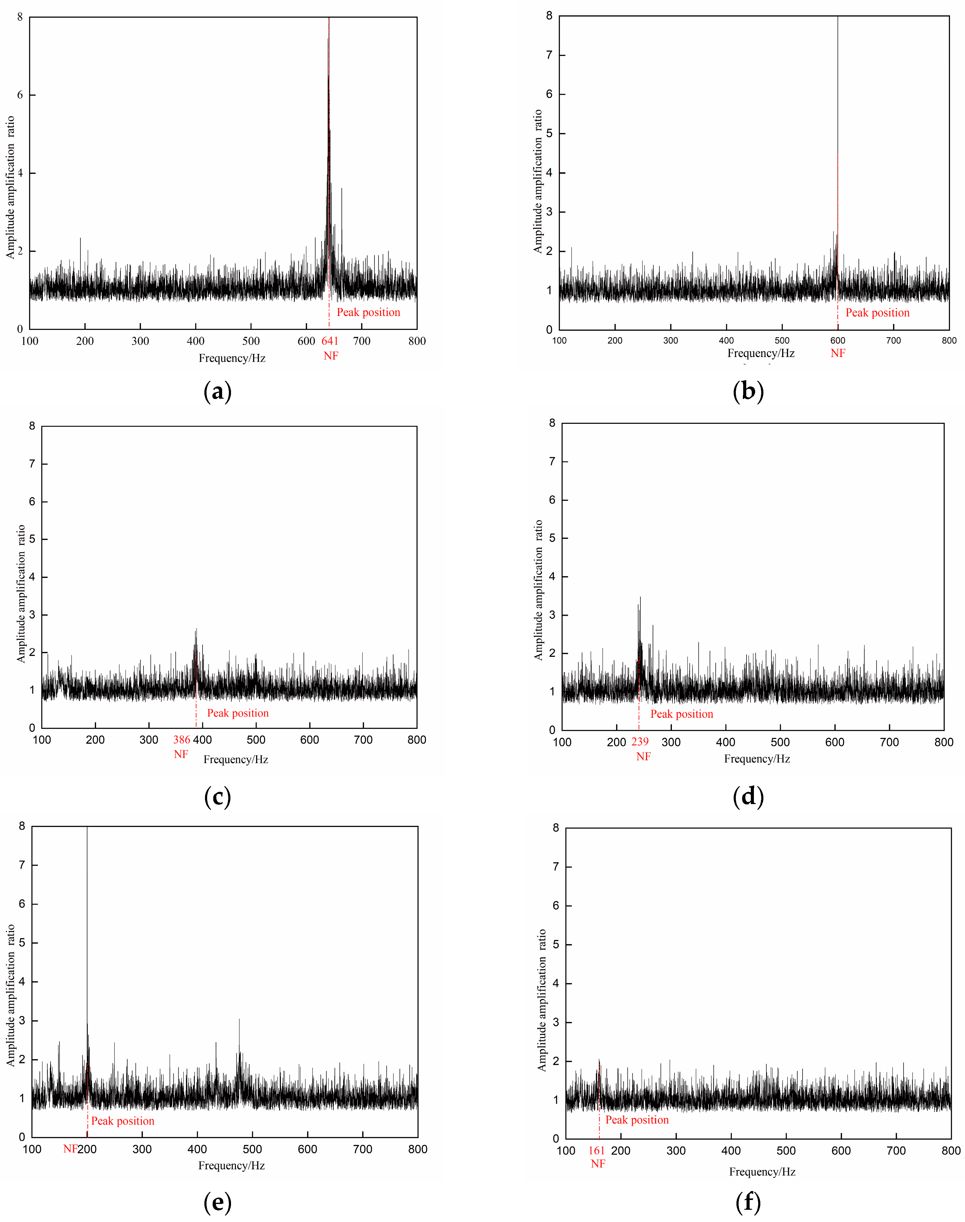
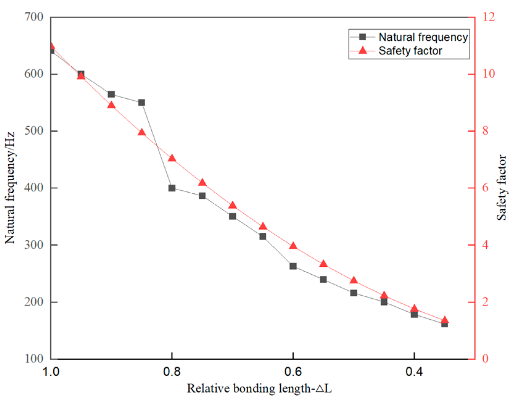
3.2.2. Correlation Analysis of Stability and NF

Following the described methodology, MEMS sensors acquired vibration curves from both bedrock and unstable rock masses, enabling the generation of frequency response function (FRF) curves across varying working conditions. The NF was derived by identifying the dominant peak within these FRF curves. As illustrated in Figure 8, the six FRF curves corresponding to distinct working conditions demonstrate a systematic leftward shift of resonance peaks (indicating frequency reduction) as the relative bonding length decreases. Quantitatively, in Condition 1 (relative bonding length = 1.0), the NF measures 641 Hz. A reduction to 0.35 in relative bonding length (Condition 14) results in a NF decline to 161 Hz, representing a 74% frequency reduction against a 65% bonding length decrease. This strong correlation confirms that diminished relative bonding lengths induce progressive declines in NF, providing a viable metric for stability assessment.
The ultimate equilibrium safety factor of unstable rock masses under each working condition was calculated using Equation (2). As shown in Figure 9, the safety factor decreases progressively with reductions in the relative bonding length of structural planes. In the initial state, the theoretical safety factor is 10.98. When the relative bonding length is reduced to 0.4, the safety factor drops to 1.75, and further decreases to 1.34 at a relative bonding length of 0.35. Both the NF and safety factor exhibit broadly consistent declining trends as the relative bonding length diminishes. However, at approximately 0.8 relative bonding length, a divergence emerges between the NF and safety factor trends. This discrepancy may stem from cutting depth inaccuracies during artificial preparation and the inherent heterogeneous anisotropic properties of the rock mass material.

3.2.3. Correlation Analysis of Stability and RMS-VAR

The vibration time–history curves of the bedrock and unstable rock mass, acquired by MEMS sensors, can be processed using Equation (8) to derive the dimensionless RMS-VAR. To correlate this ratio with rock mass stability, the three-axis acceleration data collected from the unstable rock mass were analyzed through their spatial geometric relationships, enabling the calculation of angular deviations toward the potential tipping direction. The computational framework is defined as follows:
γ x = arctan ( a x / ( a y 2 + a z 2 ) ) × 180 / π
where γ x is the MEMS sensing device x direction (tipping direction) relative to the ground horizontal tilt angle.
As shown in Figure 10, with the reduction in the relative bonding length in the structural plane of the unstable rock mass, the RMS-VAR exhibits a progressive increase, with its magnitude of change significantly exceeding that of the tilt angle. When the relative bonding length decreases from 1.0 to 0.8, the RMS-VAR from 1.02 to 1.46, while the tilt angle remains stable within this range. Upon further reduction to a relative bonding length of 0.5, the tilt angle undergoes an abrupt surge, and the RMS-VAR surpasses three times its initial amplitude. These results demonstrate that the RMS-VAR effectively captures variations in the bonding length of the dominant structural plane and provides earlier indications of stability degradation compared to detectable deformations.

4. Discussion

4.1. Dual-Indicator Stability Evaluation Model of Unstable Rock Mass

The collapse of unstable rock masses is a sudden geotechnical phenomenon where jointed slope rock masses gradually separate from the parent rock and undergo abrupt collapse. The stability of unstable rock masses can be assessed by monitoring the bonding state of internal structural planes. By using MEMS sensors to measure NF and RMS-VAR in real time, researchers can track the separation process between unstable rock masses and parent rock, enabling the real-time prediction of collapse timing.
As the relative bonding length of structural planes decreases, the NF values captured by MEMS sensors exhibit a declining trend, mirroring the reduction in the limit equilibrium safety factor. Simultaneously, the RMS-VAR between unstable rock masses and bedrock, measured via MEMS sensors, reflects changes in the structural plane’s relative bonding length and provides earlier indications of stability degradation compared to tilt angle variations.
Based on the correlated trends of decreasing stability, declining NF, and increasing RMS-VAR, a dynamic stability assessment model (Figure 11) was established [24]. In this model, NF and RMS-VAR values in the upper-left quadrant indicate stable conditions, while migration toward the lower-right quadrant signifies destabilization. These dual indicators—NF and RMS-VAR—overcome the limitations of single-parameter assessments by enabling the real-time monitoring of stability transitions.

4.2. MEMS-Based Monitoring and Early Warning System

The proposed dual-indicator MEMS monitoring system addresses the critical challenge of real-time instability assessment in unstable rock masses by leveraging NF (NF) and RMS-VAR as core parameters. Traditional seismic sensing methods, which rely on post-trigger event analysis (e.g., collapse-induced seismic waves), suffer from delayed responses and high false-negative rates in dynamic environments. Borehole-based geotechnical investigations, while effective for structural characterization, remain cost-prohibitive for localized unstable rock masses. In contrast, the MEMS-based dual-indicator approach enables the continuous vibration monitoring of both unstable rock masses and the adjacent bedrock, exploiting their differential vibration responses to derive stability metrics with high temporal resolution.
The correlation between vibration curves from bedrock and unstable rock mass sensors is highly distance-dependent. As demonstrated in prior studies, sensor proximity (<10 m) is critical for maintaining strong signal coherence (R2 > 0.85), ensuring the reliable extraction of NF and RMS-VAR. Our findings align with those of Kang et al. [25], who emphasized that signal decoupling beyond threshold distances (>15 m) introduces phase distortions, rendering response characteristics non-representative of true rock behavior. To mitigate this, we advocate for MEMS sensor deployment within optimal proximity ranges, supplemented by correlation indices to validate data fidelity—a strategy validated in slope stability monitoring.
Integrating NF and RMS-VAR with IoT cloud platforms resolves the limitations of standalone equipment performance. Localized thresholds for NF (±5% baseline), RMS-VAR (1.2–1.8), and inclined deformation (>2 mm/h) enable tiered warnings (e.g., yellow/orange/red alerts), while multi-factor big data models correlate environmental drivers (rainfall, temperature cycles) with historical instability patterns. This hybrid approach mirrors the framework proposed by Jiang et al. [26] for landslide prediction, where machine learning fused real-time sensor data with geospatial trends to achieve 92% early-warning accuracy.
However, the scalability of MEMS-based systems hinges on efficient data handling. To achieve the real-time stability monitoring of field rock masses, the dual-indicator monitoring and early-warning system based on MEMS sensors requires the integration of critical technologies including solar power supply, wireless transmission, and cloud services. While ensuring data transmission stability, it is imperative to simultaneously optimize transmission efficiency. For massive data acquisition and processing demands, the system must implement load balancing algorithms and distributed storage architecture to overcome the multi-ten-second alert issuance delays inherent in traditional warning systems. Future work should explore advanced edge computing for on-site analytics, minimizing cloud dependency in remote terrains.

5. Conclusions

Through MEMS sensing technology, the vibrational characteristic differences between bedrock and unstable rock masses were captured, yielding dynamic indices that reflect slope stability and establishing a novel methodology for collapse monitoring. Guided by the generalized spring–proton model of unstable rock masses, two monitoring parameters—NF and RMS-VAR—were proposed and validated through laboratory collapse simulations. The main conclusions are as follows:
(1)
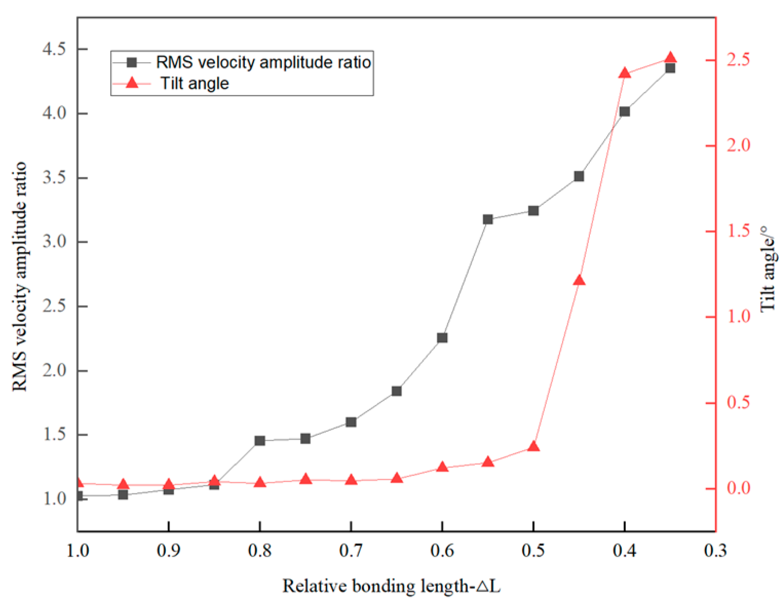
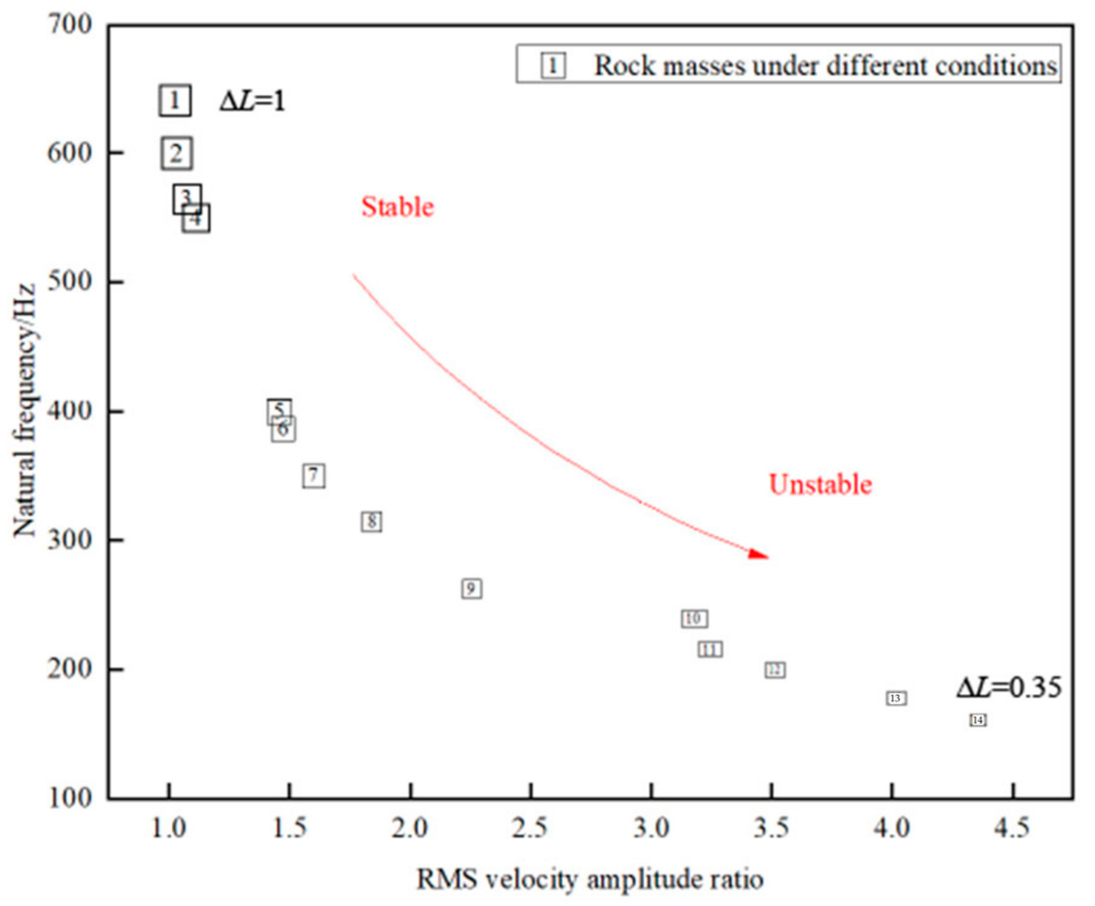
The critical structural plane length governs stability thresholds, with NF and RMS-VAR serving as effective proxies for fracture evolution. The experimental data demonstrate an inverse correlation between bonding plane length and NF, while RMS-VAR exhibit positive scaling with crack propagation rates.
(2)
MEMS sensing can accurately obtain the NF of unstable rock masses and the RMS-VAR, and can reflect the stable state of unstable rock masses in real time. The NF of unstable rock masses shows a 4:3 proportionality ratio to the limit equilibrium safety factor, and the change amplitude of RMS-VAR is three times that of the tilt angle.
(3)
Field implementation requires the integration of MEMS edge nodes, cloud-based analytics, and adaptive signal processing algorithms. This method provides a reliable technical guideline for rock mass monitoring in practical engineering and proposes a new concept for similar geological disaster monitoring and early warning.

Author Contributions

Conceptualization, M.X. and C.C.; methodology, C.C.; software, X.Z.; validation, C.C., M.X. and Y.D.; formal analysis, Y.D.; investigation, C.C.; resources, C.C.; data curation, Y.D.; writing—original draft preparation, Y.D.; writing—review and editing, C.C.; visualization, M.X.; supervision, Y.D. and X.Z.; project administration, X.Z.; funding acquisition, Y.D. and X.Z. All authors have read and agreed to the published version of the manuscript.

Funding

This research was funded by the National Key Research and Development Project of China grant number 2023YFC3081400, the National Natural Science Foundation of China grant numbers 42477167 and 41572274, and State Key Laboratory for GeoMechanics and Deep Underground Engineering, China University of Mining & Technology, Beijing grant number SKLGDUEK2130. The APC was funded by Fundamental Research Funds for the Central Universities grant number FRF-BD-20-01A. All authors have read and agreed to the published version of the manuscript.

Institutional Review Board Statement

Not applicable.

Informed Consent Statement

Not applicable.

Data Availability Statement

The original contributions presented in this study are included in the article. Further inquiries can be directed to the corresponding authors.

Conflicts of Interest

The authors declare no conflicts of interest.

Abbreviations

The following abbreviations are used in this manuscript:
MEMSMicro-Electro-Mechanical System
NFNatural Frequency
RMS-VARRoot Mean Square Velocity Amplitude Ratio
LDVLaser Doppler Vibrometer
SDOFSingle Degrees of Freedom
PCAPrincipal Component Analysis
FRFFrequency Response Function

References

  1. Luo, G.; Cheng, Q.; Shen, W.; Ling, S.; Zhang, X.; Zou, P.; Zhao, Y. Research status and development trend of high energy rockfalls. Earth Sci. 2022, 47, 913–934. [Google Scholar] [CrossRef]
  2. Du, Y.; Xie, M.W.; Jiang, Y.J.; Chen, C.; Jia, B.L.; Huo, L.C. Rock mass collapse disaster formation mechanism and early warning research review. J. Met. Mine 2021, 1, 106–119. [Google Scholar] [CrossRef]
  3. Iannucci, R.; Martino, S.; Paciello, A.; D’Amico, S.; Galea, P. Investigation of cliff instability at Għajn Ħadid Tower (Selmun Promontory, Malta) by integrated passive seismic techniques. J. Seismol. 2020, 24, 897–915. [Google Scholar] [CrossRef]
  4. Bottelin, P.; Baillet, L.; Larose, E.; Jongmans, D.; Hantz, D.; Brenguier, O.; Cadet, H.; Helmstetter, A. Monitoring rock reinforcement works with ambient vibrations: La Bourne case study (Vercors, France). Eng. Geol. 2017, 226, 136–152. [Google Scholar] [CrossRef]
  5. Mercerat, E.D.; Payeur, J.B.; Bertrand, E.; Malascrabes, M.; Pernoud, M.; Chamberland, Y. Deciphering the dynamics of a heterogeneous sea cliff using ambient vibrations: Case study of the Sutta-Rocca overhang (southern Corsica, France). Geophys. J. Int. 2020, 224, 813–832. [Google Scholar] [CrossRef]
  6. Chen, H.K.; Zhou, Y.T.; Tang, H.M. Based on the analysis of sliding type to remove unstable rock mass blasting dynamic stability calculation method. J. Vib. Shock 2014, 33, 31–34+41. [Google Scholar] [CrossRef]
  7. Chen, H.K.; Zhang, R.G.; Tang, H.M.; Zhao, X.T. Pressure shear type unstable rock mass damage play rushed to study dynamic parameters. J. Vib. Shock 2012, 31, 30–33. [Google Scholar] [CrossRef]
  8. Taruselli, M.; Arosio, D.; Longoni, L.; Papini, M.; Zanzi, L. Seismic noise monitoring of a small rock block collapse test. Geophys. J. Int. 2021, 224, 207–215. [Google Scholar] [CrossRef]
  9. Burjánek, J.; Gischig, V.; Moore, J.R.; Fäh, D. Ambient vibration characterization and monitoring of a rock slope close to collapse. Geophys. J. Int. 2018, 212, 297–310. [Google Scholar] [CrossRef]
  10. Glueer, F.; Mreyen, A.-S.; Cauchie, L.; Havenith, H.-B.; Bergamo, P.; Halló, M.; Fäh, D. Integrating Seismic Methods for Characterizing and Monitoring Landslides: A Case Study of the Heinzenberg Deep-Seated Gravitational Slope Deformation (Switzerland). Geosciences 2024, 14, 28. [Google Scholar] [CrossRef]
  11. Häusler, M.; Michel, C.; Burjánek, J.; Fäh, D. Fracture Network Imaging on Rock Slope Instabilities Using Resonance Mode Analysis. Geophys. Res. Lett. 2019, 46, 6497–6506. [Google Scholar] [CrossRef]
  12. Häusler, M.; Michel, C.; Burjánek, J.; Fäh, D. Monitoring the Preonzo Rock Slope Instability Using Resonance Mode Analysis. J. Geophys. Res. Earth Surf. 2021, 126, e2020JF005709. [Google Scholar] [CrossRef]
  13. Wu, D.; Liang, T.; Yang, Y.; Pei, Q.; Yi, Y.; Wu, J.; Li, D. Experimental study on displacement monitoring of instable highway slope based on MEMS sensors. Front. Earth Sci. 2025, 13, 1541217. [Google Scholar] [CrossRef]
  14. Praveen, H.M.; Singh, S.P. An investigation into practical implementation of mems sensors for low-speed condition monitoring applications. Exp. Tech. 2025, 49, 1–18. [Google Scholar] [CrossRef]
  15. Bolla, A.; Paronuzzi, P. Numerical investigation of the pre-collapse behavior and internal damage of an unstable rock slope. Rock Mech. Rock Eng. 2020, 53, 2279–2300. [Google Scholar] [CrossRef]
  16. Samadi, H.; Farrokh, E. Utilization of rock mass parameters for performance prediction of rock tbms using machine learning algorithms. SRPH J. Fundam. Sci. Technol. 2021, 3, 1–9. [Google Scholar] [CrossRef]
  17. Chen, H.K.; Wang, S.J.; Chen, J. Theoretical framework of physical evolution of unstable rock mass collapse disaster and disaster outbreak time. J. Chongqing Norm. Univ. 2020, 37, 121–128. [Google Scholar] [CrossRef]
  18. Colombero, C.; Comina, C.; Vinciguerra, S.; Benson, P.M. Microseismicity of an unstable rock mass: From field monitoring to laboratory testing. J. Geophys. Res. Solid Earth 2018, 123, 1673–1693. [Google Scholar] [CrossRef]
  19. Liu, X.R.; Guo, X.Y.; Zhou, X.H.; Luo, X.Y.; Wang, H.; Li, P.Y.; Zhou, F.C. Study on macro-meso shear transfixion mechanisms and mechanical properties of shear band-bedrock interfaces of dangerous rock on reservoir bank. Chin. J. Rock Mech. Eng. 2024, 43, 1096–1109. [Google Scholar] [CrossRef]
  20. He, Z. Study on Instability Prediction Model of Splitting Rock Mass on Slopes; Beijing University of Science and Technology: Beijing, China, 2023. [Google Scholar] [CrossRef]
  21. Li, B.; Zhao, W.; Miao, Y.; Tian, W.; Liao, W. A method for dynamic parameter identification of an industrial robot based on frequency response function. Int. J. Mech. Syst. Dyn. 2024, 4, 461–471. [Google Scholar] [CrossRef]
  22. Dahiya, N.; Pandit, K.; Sarkar, S.; Pain, A. Various aspects of rockfall hazards along the mountain roads in India: A systematic review. Indian Geotech. J. 2024. [Google Scholar] [CrossRef]
  23. Raja, S.; Abhishek, M.; Balegar, N.; Kristharaj, L.; Yeligar, S. Prediction of rockfall from highwall slope in an open cast mine. J. Mines Met. Fuels 2024, 72, 147–163. [Google Scholar] [CrossRef]
  24. Li, L.Q.; Huang, R.Q. Steep dip bedding slope instability mechanism analysis. J. Eng. Sci. Technol. 2018, 50, 54–63. [Google Scholar] [CrossRef]
  25. Kang, X.; Huang, L.; Zhang, Y.; Yun, S.; Jiao, B.; Liu, X.; Zhang, J.; Li, Z.; Zhang, H. Wearable Multi-Channel Pulse Signal Acquisition System Based on Flexible MEMS Sensor Arrays with TSV Structure. Biomimetics 2023, 8, 207. [Google Scholar] [CrossRef]
  26. Jiang, H.; Wang, Y.; Guo, Z.; Zhou, H.; Wu, J.; Li, X. Landslide Displacement Prediction Stacking Deep Learning Algorithms: A Case Study of Shengjibao Landslide in the Three Gorges Reservoir Area of China. Water 2024, 16, 3141. [Google Scholar] [CrossRef]
Figure 1. Working principle of MEMS sensor. (a) Application method of MEMS sensors. (b) MEMS sensing mechanisms.
Applsci 15 04210 g001
Figure 2. Schematic diagram of overthrown unstable rock mass.
Applsci 15 04210 g002
Figure 3. SDOF spring–mass oscillator of an unstable rock.
Applsci 15 04210 g003
Figure 4. Simulated unstable rock collapse monitoring system.
Applsci 15 04210 g004
Figure 5. Simulation of the collapse process of unstable rock. (a) Rock mass formed by pouring. (b) Cut of the structural plane.
Applsci 15 04210 g005
Figure 6. Data acquisition sensing equipment. (a) MEMS accelerometer. (b) Signal collector. (c) LDV equipment.
Applsci 15 04210 g006
Figure 7. Comparison between LDV and MEMS sensor. (a) Temporal region comparison. (b) Frequency-domain signal comparison.
Applsci 15 04210 g007
Figure 8. Frequency response curve under typical working conditions. (a) Frequency response curve of unstable rock mass in working condition 1. (b) Frequency response curve of unstable rock mass in working condition 2. (c) Frequency response curve of unstable rock mass in working condition 6. (d) Frequency response curve of working condition 9. (e) Frequency response curve of unstable rock mass under working condition 12. (f) Frequency response curve of unstable rock mass under working condition 14.
Applsci 15 04210 g008
Figure 9. Relation between NF and safety factor of unstable rock.
Applsci 15 04210 g009
Figure 10. Relation between RMS-VAR and tilt angle.
Applsci 15 04210 g010
Figure 11. Dual-indicator evaluation model of unstable rock.
Applsci 15 04210 g011
Table 1. Physical and mechanical properties of the rock blocks.
Density/(kg/m3)Modulus of Elasticity/GPaPoisson’s RatioTensile Strength/MPaCohesion/MPa
2230.002.400.280.0980.926
Table 2. Main performance parameters of the device.
Model NumberFrequency Range/kHzRangeResolutionSize/mm
INV9832-501~1050 g0.01 mg19 × 19
RSV-1500~251 m/s0.5 μm/s402 × 165 × 145 mm
Table 3. Simulated working conditions of unstable rock.
Condition1234567891011121314
L/cm00.511.522.533.544.555.566.5
Δ L 10.950.900.850.80.750.70.650.60.550.500.450.400.35
Disclaimer/Publisher’s Note: The statements, opinions and data contained in all publications are solely those of the individual author(s) and contributor(s) and not of MDPI and/or the editor(s). MDPI and/or the editor(s) disclaim responsibility for any injury to people or property resulting from any ideas, methods, instructions or products referred to in the content.

